EP1623958B1 - Procédé et dispositifs de traitement de fluides pollués par photocatalyse - Google Patents
Procédé et dispositifs de traitement de fluides pollués par photocatalyse Download PDFInfo
- Publication number
- EP1623958B1 EP1623958B1 EP20050291632 EP05291632A EP1623958B1 EP 1623958 B1 EP1623958 B1 EP 1623958B1 EP 20050291632 EP20050291632 EP 20050291632 EP 05291632 A EP05291632 A EP 05291632A EP 1623958 B1 EP1623958 B1 EP 1623958B1
- Authority
- EP
- European Patent Office
- Prior art keywords
- wall
- flexible substrate
- face
- photocatalytic
- fluid
- Prior art date
- Legal status (The legal status is an assumption and is not a legal conclusion. Google has not performed a legal analysis and makes no representation as to the accuracy of the status listed.)
- Expired - Lifetime
Links
Images

Classifications
-
- C—CHEMISTRY; METALLURGY
- C02—TREATMENT OF WATER, WASTE WATER, SEWAGE, OR SLUDGE
- C02F—TREATMENT OF WATER, WASTE WATER, SEWAGE, OR SLUDGE
- C02F1/00—Treatment of water, waste water, or sewage
- C02F1/72—Treatment of water, waste water, or sewage by oxidation
- C02F1/725—Treatment of water, waste water, or sewage by oxidation by catalytic oxidation
-
- B—PERFORMING OPERATIONS; TRANSPORTING
- B01—PHYSICAL OR CHEMICAL PROCESSES OR APPARATUS IN GENERAL
- B01J—CHEMICAL OR PHYSICAL PROCESSES, e.g. CATALYSIS OR COLLOID CHEMISTRY; THEIR RELEVANT APPARATUS
- B01J19/00—Chemical, physical or physico-chemical processes in general; Their relevant apparatus
- B01J19/08—Processes employing the direct application of electric or wave energy, or particle radiation; Apparatus therefor
- B01J19/12—Processes employing the direct application of electric or wave energy, or particle radiation; Apparatus therefor employing electromagnetic waves
- B01J19/122—Incoherent waves
- B01J19/127—Sunlight; Visible light
-
- C—CHEMISTRY; METALLURGY
- C02—TREATMENT OF WATER, WASTE WATER, SEWAGE, OR SLUDGE
- C02F—TREATMENT OF WATER, WASTE WATER, SEWAGE, OR SLUDGE
- C02F1/00—Treatment of water, waste water, or sewage
- C02F1/30—Treatment of water, waste water, or sewage by irradiation
-
- C—CHEMISTRY; METALLURGY
- C02—TREATMENT OF WATER, WASTE WATER, SEWAGE, OR SLUDGE
- C02F—TREATMENT OF WATER, WASTE WATER, SEWAGE, OR SLUDGE
- C02F1/00—Treatment of water, waste water, or sewage
- C02F1/30—Treatment of water, waste water, or sewage by irradiation
- C02F1/32—Treatment of water, waste water, or sewage by irradiation with ultraviolet light
- C02F1/325—Irradiation devices or lamp constructions
-
- B—PERFORMING OPERATIONS; TRANSPORTING
- B01—PHYSICAL OR CHEMICAL PROCESSES OR APPARATUS IN GENERAL
- B01J—CHEMICAL OR PHYSICAL PROCESSES, e.g. CATALYSIS OR COLLOID CHEMISTRY; THEIR RELEVANT APPARATUS
- B01J2219/00—Chemical, physical or physico-chemical processes in general; Their relevant apparatus
- B01J2219/08—Processes employing the direct application of electric or wave energy, or particle radiation; Apparatus therefor
- B01J2219/0873—Materials to be treated
- B01J2219/0877—Liquid
-
- B—PERFORMING OPERATIONS; TRANSPORTING
- B01—PHYSICAL OR CHEMICAL PROCESSES OR APPARATUS IN GENERAL
- B01J—CHEMICAL OR PHYSICAL PROCESSES, e.g. CATALYSIS OR COLLOID CHEMISTRY; THEIR RELEVANT APPARATUS
- B01J2219/00—Chemical, physical or physico-chemical processes in general; Their relevant apparatus
- B01J2219/08—Processes employing the direct application of electric or wave energy, or particle radiation; Apparatus therefor
- B01J2219/0873—Materials to be treated
- B01J2219/0892—Materials to be treated involving catalytically active material
-
- B—PERFORMING OPERATIONS; TRANSPORTING
- B01—PHYSICAL OR CHEMICAL PROCESSES OR APPARATUS IN GENERAL
- B01J—CHEMICAL OR PHYSICAL PROCESSES, e.g. CATALYSIS OR COLLOID CHEMISTRY; THEIR RELEVANT APPARATUS
- B01J2219/00—Chemical, physical or physico-chemical processes in general; Their relevant apparatus
- B01J2219/32—Details relating to packing elements in the form of grids or built-up elements for forming a unit of module inside the apparatus for mass or heat transfer
- B01J2219/322—Basic shape of the elements
- B01J2219/32203—Sheets
- B01J2219/32206—Flat sheets
-
- B—PERFORMING OPERATIONS; TRANSPORTING
- B01—PHYSICAL OR CHEMICAL PROCESSES OR APPARATUS IN GENERAL
- B01J—CHEMICAL OR PHYSICAL PROCESSES, e.g. CATALYSIS OR COLLOID CHEMISTRY; THEIR RELEVANT APPARATUS
- B01J2219/00—Chemical, physical or physico-chemical processes in general; Their relevant apparatus
- B01J2219/32—Details relating to packing elements in the form of grids or built-up elements for forming a unit of module inside the apparatus for mass or heat transfer
- B01J2219/322—Basic shape of the elements
- B01J2219/32203—Sheets
- B01J2219/32224—Sheets characterised by the orientation of the sheet
- B01J2219/32227—Vertical orientation
-
- B—PERFORMING OPERATIONS; TRANSPORTING
- B01—PHYSICAL OR CHEMICAL PROCESSES OR APPARATUS IN GENERAL
- B01J—CHEMICAL OR PHYSICAL PROCESSES, e.g. CATALYSIS OR COLLOID CHEMISTRY; THEIR RELEVANT APPARATUS
- B01J2219/00—Chemical, physical or physico-chemical processes in general; Their relevant apparatus
- B01J2219/32—Details relating to packing elements in the form of grids or built-up elements for forming a unit of module inside the apparatus for mass or heat transfer
- B01J2219/322—Basic shape of the elements
- B01J2219/32203—Sheets
- B01J2219/32224—Sheets characterised by the orientation of the sheet
- B01J2219/32234—Inclined orientation
-
- B—PERFORMING OPERATIONS; TRANSPORTING
- B01—PHYSICAL OR CHEMICAL PROCESSES OR APPARATUS IN GENERAL
- B01J—CHEMICAL OR PHYSICAL PROCESSES, e.g. CATALYSIS OR COLLOID CHEMISTRY; THEIR RELEVANT APPARATUS
- B01J2219/00—Chemical, physical or physico-chemical processes in general; Their relevant apparatus
- B01J2219/32—Details relating to packing elements in the form of grids or built-up elements for forming a unit of module inside the apparatus for mass or heat transfer
- B01J2219/322—Basic shape of the elements
- B01J2219/32203—Sheets
- B01J2219/32237—Sheets comprising apertures or perforations
-
- B—PERFORMING OPERATIONS; TRANSPORTING
- B01—PHYSICAL OR CHEMICAL PROCESSES OR APPARATUS IN GENERAL
- B01J—CHEMICAL OR PHYSICAL PROCESSES, e.g. CATALYSIS OR COLLOID CHEMISTRY; THEIR RELEVANT APPARATUS
- B01J2219/00—Chemical, physical or physico-chemical processes in general; Their relevant apparatus
- B01J2219/32—Details relating to packing elements in the form of grids or built-up elements for forming a unit of module inside the apparatus for mass or heat transfer
- B01J2219/324—Composition or microstructure of the elements
- B01J2219/32458—Paper
-
- B—PERFORMING OPERATIONS; TRANSPORTING
- B01—PHYSICAL OR CHEMICAL PROCESSES OR APPARATUS IN GENERAL
- B01J—CHEMICAL OR PHYSICAL PROCESSES, e.g. CATALYSIS OR COLLOID CHEMISTRY; THEIR RELEVANT APPARATUS
- B01J2219/00—Chemical, physical or physico-chemical processes in general; Their relevant apparatus
- B01J2219/32—Details relating to packing elements in the form of grids or built-up elements for forming a unit of module inside the apparatus for mass or heat transfer
- B01J2219/324—Composition or microstructure of the elements
- B01J2219/32466—Composition or microstructure of the elements comprising catalytically active material
-
- C—CHEMISTRY; METALLURGY
- C02—TREATMENT OF WATER, WASTE WATER, SEWAGE, OR SLUDGE
- C02F—TREATMENT OF WATER, WASTE WATER, SEWAGE, OR SLUDGE
- C02F2201/00—Apparatus for treatment of water, waste water or sewage
- C02F2201/008—Mobile apparatus and plants, e.g. mounted on a vehicle
-
- C—CHEMISTRY; METALLURGY
- C02—TREATMENT OF WATER, WASTE WATER, SEWAGE, OR SLUDGE
- C02F—TREATMENT OF WATER, WASTE WATER, SEWAGE, OR SLUDGE
- C02F2201/00—Apparatus for treatment of water, waste water or sewage
- C02F2201/32—Details relating to UV-irradiation devices
- C02F2201/322—Lamp arrangement
- C02F2201/3227—Units with two or more lamps
-
- C—CHEMISTRY; METALLURGY
- C02—TREATMENT OF WATER, WASTE WATER, SEWAGE, OR SLUDGE
- C02F—TREATMENT OF WATER, WASTE WATER, SEWAGE, OR SLUDGE
- C02F2305/00—Use of specific compounds during water treatment
- C02F2305/10—Photocatalysts
Definitions
- the invention relates to a method for the treatment of fluids polluted by photocatalysis using a flexible substrate carrying photocatalytic compounds, such as paper or tissue, and devices for application.
- Photocatalyst treatment devices for polluted fluid comprising a flexible substrate carrying photocatalytic compounds and support means holding the flexible substrate so as to leave one of the faces of the substrate free to allow fluid to flow along said free face.
- Lighting means being arranged to illuminate said free face at a wavelength adapted to trigger chemical reactions for reducing organic pollutants by photocatalysis on the surface of the substrate.
- document is known GB 2,359,301 a device comprising rigid walls whose two faces are covered with fabrics carrying photocatalytic compounds.
- a light source allows illumination of the free faces of the substrate along which water flows to promote photocatalysis reactions at the free surface of the flexible substrate.
- the subject of the invention is a process for the treatment by photocatalysis of polluted fluid whose efficiency is increased compared to that of the known processes.
- a method for treating photocatalysis of polluted fluid is proposed. during which a flexible substrate carrying photocatalytic compounds is maintained so as to leave free a first face along which the fluid is poured by illuminating the first face of the substrate, and in which, according to the invention, it also illuminates a second side of the photocatalytic paper sheet.
- the invention also relates to a device specially adapted to the implementation of the method of the invention, comprising means for supporting a flexible substrate carrying photocatalytic compounds adapted to leave free at least the first face of the substrate, circulation means being adapted to cause a fluid flow along the first face, the support means being adapted to allow illumination of the second face of the flexible substrate.
- the device is in the form of an assembly adapted to be towed by a tractor and comprises a wall 1 of reinforced glass extending along an inclined plane.
- the wall 1 is surmounted by a bowl 2.
- the wall 1 is covered with a sheet of photocatalytic paper 3 and extends overhanging a tank 4.
- a pump 5 is arranged to pump the fluid contained in the tank 4 to bring it into the bowl 2.
- the operation of the device is as follows.
- the tank 4 is previously filled with polluted fluid to be treated.
- the pump 5 is started, so that the fluid is transferred from the tank 4 into the bowl 2.
- the fluid overflows and flows on the free face of the sheet of paper photocatalytic 3 covering the wall 1 to fall back into the tank 4, so that the fluid travels through a closed circuit.
- the embodiment according to the invention of the wall 1 in a transparent material makes it possible to illuminate the face of the sheet of photocatalytic paper 3 which extends against the wall 1, which contributes to increasing the rate of chemical reactions on the free surface of the sheet of photocatalytic paper 3.
- a reflector 6 provided with a tip for its plugging into the earth is arranged to return a portion of the sun's rays on the inner face of the wall 1.
- the face of the wall 1 which receives the sheet of photocatalytic paper 3 is illuminated directly by the sun, while the other side is illuminated via the reflector 6, which allows an action of the sun's rays on both sides of the wall 1, therefore on both sides of the sheet of photocatalytic paper 3.
- the circulation in closed circuit is continued until the desired level of pollution.
- Increasing the efficiency of the photocatalysis by illumination according to the invention of the two faces of the photocatalytic paper sheet makes it possible to reduce the treatment time.
- the sheet of photocatalytic paper 3 extends to also cover the bottom of the bowl 2. Pollutants falling to the bottom of the bowl 2 are then retained by the sheet of photocatalytic paper to prevent them from polluting the portion of the sheet which extends against the wall 1, which could inhibit part of the chemical reactions.
- the bowl 2 itself is made of transparent material, which makes it possible to illuminate the face of the paper 3 which extends against the bottom of the bowl 2, thus favoring a certain number of chemical reactions directly in the bowl 2.
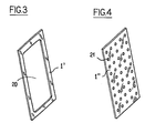
- the wall 1 is replaced by a wall 1 'which has a central opening 20 for illuminating the rear face of the photocatalytic paper sheet.
- the wall 1 is replaced by a wall 1 "which has orifices 21 (only one is referenced) regularly distributed to illuminate the rear face of the photocatalytic paper sheet.
- the flexible substrate is paper here, other flexible substrates such as fabric may be used.
- the support means comprise a transparent wall or a perforated wall
- the wall may take any form as long as it allows illumination of the second face of the substrate.
- the wall may be made of mesh or be formed of a network of cables stretched on a frame.
- the wall may not be flat.
Landscapes
- Chemical & Material Sciences (AREA)
- Organic Chemistry (AREA)
- Water Supply & Treatment (AREA)
- Hydrology & Water Resources (AREA)
- Engineering & Computer Science (AREA)
- Environmental & Geological Engineering (AREA)
- Life Sciences & Earth Sciences (AREA)
- Health & Medical Sciences (AREA)
- Toxicology (AREA)
- Chemical Kinetics & Catalysis (AREA)
- Physics & Mathematics (AREA)
- Electromagnetism (AREA)
- General Health & Medical Sciences (AREA)
- Catalysts (AREA)
Description
- L'invention concerne un procédé de traitement de fluides pollués par photocatalyse à l'aide de substrat souple porteur de composés photocatalytiques, tels que du papier ou du tissu, et des dispositifs faisant application.
- On connaît des dispositifs de traitement par photocatalyse de fluide pollué, comportant un substrat souple porteur de composés photocatalytiques et des moyens de support maintenant le substrat souple de façon à laisser libre l'une des faces du substrat pour permettre un écoulement du fluide le long de ladite face libre. Des moyens d'éclairage étant disposés pour éclairer ladite face libre selon une longueur d'onde adaptée à déclencher des réactions chimiques de réduction des polluants organiques par photocatalyse à la surface du substrat.
- Par exemple, on connaît du document
GB 2 359 301 - Procédés et dispositifs similaires sont également connus à partir des documents
US 6 063 343 etEP 0 993 859 . - L'efficacité du traitement est fonction de l'intensité lumineuse. Or cette efficacité tend vers une limite difficilement franchissable même avec des grandes intensités lumineuses.
- L'invention a pour objet un procédé de traitement par photocatalyse de fluide pollué dont l'efficacité est accrue par rapport à celle des procédés connus.
- En vue de la réalisation de ce but, on propose un procédé de traitement par photocatalyse de fluide pollué, lors duquel on maintient un substrat souple porteur de composés photocatalytiques de façon à laisser libre une première face le long de laquelle on fait couler le fluide en éclairant la première face du substrat, et lors duquel, selon l'invention, l'on éclaire également une seconde face de la feuille de papier photocatalytique.
- Le déposant a en effet constaté par expérimentation que l'éclairage de l'autre face du substrat souple augmente l'efficacité du traitement.
- L'invention est également relative à un dispositif spécialement adapté à la mise en oeuvre du procédé de l'invention, comportant des moyens de support d'un substrat souple porteur de composés photocatalytiques adaptés à laisser libre au moins la première face du substrat, des moyens de circulation étant adaptés à provoquer un écoulement du fluide le long de la première face, les moyens de support étant adaptés à permettre un éclairage de la seconde face du substrat souple.
- L'invention sera mieux comprise à la lumière de la description qui suit en référence aux figures des dessins annexés parmi lesquelles :
- la
figure 1 est une vue en perspective d'un dispositif remorquable de traitement par photocatalyse des fluides pollués selon un premier mode particulier de réalisation de l'invention ; - la
figure 2 est une vue en coupe partielle selon le plan P de lafigure 1 ; - la
figure 3 est une vue en perspective des moyens de support du substrat souple du dispositif de lafigure 1 , selon une variante de réalisation; - la
figure 4 est une vue en perspective des moyens de support du substrat souple du dispositif de lafigure 1 , selon une autre variante de réalisation; - En référence à la
figure 1 , et selon un mode de réalisation particulier de l'invention, le dispositif se présente sous la forme d'un ensemble apte à être remorqué par un tracteur et comporte une paroi 1 en verre armé s'étendant selon un plan incliné. La paroi 1 est surmontée d'une cuvette 2. La paroi 1 est recouverte d'une feuille de papier photocatalytique 3 et s'étend en surplomb d'un réservoir 4. Une pompe 5 est agencée pour pomper le fluide contenu dans le réservoir 4 pour l'amener dans la cuvette 2. - Le fonctionnement du dispositif est le suivant. Le réservoir 4 est préalablement rempli de fluide pollué à traiter. Puis la pompe 5 est mise en route, de sorte que le fluide est transféré du réservoir 4 dans la cuvette 2. Lorsque le niveau de la cuvette 2 est suffisant, le fluide déborde et s'écoule sur la face libre de la feuille de papier photocatalytique 3 recouvrant la paroi 1 pour retomber dans le réservoir 4, de sorte que le fluide parcourt un circuit fermé.
- Lors du séjour du fluide dans la cuvette 2, celui-ci subit une décantation de sorte que les polluants les plus lourds, en particulier les polluants non organiques, tombent au fond de la cuvette 2. Lors du passage du fluide sur la paroi 1, des réactions chimiques se produisent à la surface libre de la feuille de papier photocatalytique 3 ayant pour conséquence de réduire les polluants organiques (urée, engrais, etc...). Ces réactions chimiques sont catalysées par l'éclairage par le soleil de la face libre de la feuille de papier photocatalytique 3.
- La réalisation selon l'invention de la paroi 1 en un matériau transparent permet l'éclairage de la face de la feuille de papier photocatalytique 3 qui s'étend contre la paroi 1, ce qui contribue à augmenter le taux de réactions chimiques sur la surface libre de la feuille de papier photocatalytique 3. A cet égard un réflecteur 6 muni d'une pointe pour son enfichage en terre est disposé de façon à renvoyer une partie des rayons du soleil sur la face interne de la paroi 1. Comme cela est schématisé à la
figure 2 , la face de la paroi 1 qui reçoit la feuille de papier photocatalytique 3 est éclairée directement par le soleil, tandis que l'autre face est éclairée via le réflecteur 6, ce qui permet une action des rayons du soleil sur les deux faces de la paroi 1, donc sur les deux faces de la feuille de papier photocatalytique 3. - La circulation en circuit fermé est ainsi poursuivie jusqu'à obtention du niveau de dépollution désiré. L'augmentation de l'efficacité de la photocatalyse par éclairage selon l'invention des deux faces de la feuille de papier photocatalytique permet de diminuer le temps de traitement.
- Selon un aspect particulier de l'invention illustré à la
figure 2 , la feuille de papier photocatalytique 3 s'étend pour recouvrir également le fond de la cuvette 2. Les polluants tombant au fond de la cuvette 2 sont alors retenus par la feuille de papier photocatalytique pour éviter qu'ils ne polluent la partie de la feuille qui s'étend contre la paroi 1, ce qui risquerait d'inhiber une partie des réactions chimiques. - Selon une disposition intéressante de l'invention, la cuvette 2 elle-même est en matériau transparent, ce qui permet l'éclairage de la face du papier 3 qui s'étend contre le fond de la cuvette 2, favorisant ainsi un certain nombre de réactions chimiques directement dans la cuvette 2.
- Selon une variante de réalisation illustrée à la
figure 3 , la paroi 1 est remplacée par une paroi 1' qui comporte une ouverture centrale 20 permettant l'éclairage de la face arrière de la feuille de papier photocatalytique. - Selon une autre variante de réalisation illustrée à la
figure 4 , la paroi 1 est remplacée par une paroi 1" qui comporte des orifices 21 (un seul est référencé) régulièrement répartis permettant l'éclairage de la face arrière de la feuille de papier photocatalytique. - L'invention n'est pas limitée à ce qui vient d'être décrit et englobe toute variante entrant dans le cadre défini par les revendications.
- En particulier, bien que le substrat souple soit ici du papier, on pourra utiliser d'autres substrats souples comme du tissu.
- Bien que dans le mode particulier de réalisation, les moyens de support comportent une paroi transparente ou encore une paroi ajourée, la paroi pourra prendre toute forme du moment qu'elle permette un éclairage de la seconde face du substrat. Par exemple, la paroi pourra être réalisée en grillage ou être formée d'un réseau de câbles tendus sur un cadre. La paroi peut ne pas être plane.
Claims (5)
- Dispositif de traitement par photocatalyse de fluide pollué, comportant des moyens de support (1, 1') d'un substrat souple (3) porteur de composés photo-catalytiques qui sont adaptés à laisser libre au moins une première face du substrat souple, le dispositif comportant des moyens de circulation (5) adaptés à provoquer un écoulement du fluide uniquement le long de la première face du substrat souple, caractérisé en ce que les moyens de support comportent une paroi (1) contre laquelle une seconde face du substrat souple s'étend et qui est adaptée à permettre un éclairage de la seconde face du substrat souple à travers la paroi, le dispositif comportant un réflecteur (6) est disposé par rapport à la paroi (1) pour réfléchir de la lumière vers la paroi en vue d'éclairer la seconde face du substrat souple.
- Dispositif de traitement par photocatalyse de fluide pollué selon la revendication 1, comportant une cuvette (2) en amont de la paroi (1) en référence à un sens d'écoulement du fluide, le substrat souple (3) s'étendant pour recouvrir également un fond de la cuvette (2).
- Dispositif selon la revendication 2, dans lequel la cuvette (2) est adaptée à permettre un éclairage de la seconde face du substrat souple recouvrant la cuvette.
- Dispositif selon la revendication 1, dans lequel la paroi (1) est en matériau transparent à des ondes électromagnétiques qui catalysent des réactions chimiques à la surface du papier photocatalytique (3).
- Dispositif selon la revendication 2, dans lequel la paroi est ajourée (1', 1").
Applications Claiming Priority (1)
| Application Number | Priority Date | Filing Date | Title |
|---|---|---|---|
| FR0408512A FR2873679B1 (fr) | 2004-08-02 | 2004-08-02 | Procede de traitement de liquides pollues par photocatalyse et dispositifs faisant application |
Publications (2)
| Publication Number | Publication Date |
|---|---|
| EP1623958A1 EP1623958A1 (fr) | 2006-02-08 |
| EP1623958B1 true EP1623958B1 (fr) | 2014-01-01 |
Family
ID=34947504
Family Applications (1)
| Application Number | Title | Priority Date | Filing Date |
|---|---|---|---|
| EP20050291632 Expired - Lifetime EP1623958B1 (fr) | 2004-08-02 | 2005-08-01 | Procédé et dispositifs de traitement de fluides pollués par photocatalyse |
Country Status (2)
| Country | Link |
|---|---|
| EP (1) | EP1623958B1 (fr) |
| FR (1) | FR2873679B1 (fr) |
Families Citing this family (1)
| Publication number | Priority date | Publication date | Assignee | Title |
|---|---|---|---|---|
| CN110776082B (zh) * | 2019-11-08 | 2021-06-08 | 河海大学 | 一种花形自展叶式光催化净污浮床 |
Family Cites Families (9)
| Publication number | Priority date | Publication date | Assignee | Title |
|---|---|---|---|---|
| JPH08224574A (ja) * | 1995-02-20 | 1996-09-03 | Seiwa Kogyo Kk | 水処理装置 |
| US5790934A (en) * | 1996-10-25 | 1998-08-04 | E. Heller & Company | Apparatus for photocatalytic fluid purification |
| JPH1190421A (ja) * | 1997-09-24 | 1999-04-06 | Ishikawajima Harima Heavy Ind Co Ltd | 貯水槽 |
| EP0993859A1 (fr) * | 1998-09-18 | 2000-04-19 | Hitachi Metals, Ltd. | Dispositif de filtre photocatalytique tridimensionnel |
| JP2001136862A (ja) * | 1999-11-12 | 2001-05-22 | Hitachi Zosen Corp | 光触媒皮膜付き側壁を有する水槽 |
| JP2001231395A (ja) * | 2000-02-21 | 2001-08-28 | Nakajima Suisan Co Ltd | 光触媒を利用した稚魚の斃死率改善システム |
| JP3691005B2 (ja) * | 2001-08-28 | 2005-08-31 | 毅 相原 | 有機物処理装置 |
| JP3892277B2 (ja) * | 2001-10-30 | 2007-03-14 | 松下冷機株式会社 | 保鮮庫 |
| JP2004100110A (ja) * | 2002-09-11 | 2004-04-02 | Asahi Kasei Chemicals Corp | 光触媒担持紙 |
-
2004
- 2004-08-02 FR FR0408512A patent/FR2873679B1/fr not_active Expired - Fee Related
-
2005
- 2005-08-01 EP EP20050291632 patent/EP1623958B1/fr not_active Expired - Lifetime
Also Published As
| Publication number | Publication date |
|---|---|
| FR2873679A1 (fr) | 2006-02-03 |
| EP1623958A1 (fr) | 2006-02-08 |
| FR2873679B1 (fr) | 2007-11-30 |
Similar Documents
| Publication | Publication Date | Title |
|---|---|---|
| FR2725916A1 (fr) | Reservoir de traitement de l'eau par decantation | |
| EP0052864B1 (fr) | Dispositif pour la décantation d'un fluide | |
| FR3023281A1 (fr) | Dispositif de traitement et de recyclage des eaux grises et procede de retro-lavage | |
| LU82489A1 (fr) | Fosse d'aisances septique mobile | |
| FR2475925A1 (fr) | Ensemble agitateur de fluides | |
| EP1064068A1 (fr) | Dispositif assurant la recuperation des flottants dans des bassins de decantation | |
| EP1623958A1 (fr) | Procédé et dispositifs de traitement de fluides pollués par photocatalyse | |
| FR2509337A1 (fr) | Dispositif de flottation pour le traitement de vieux papiers | |
| EP0672440B1 (fr) | Filtre pour l'épuration des eaux | |
| FR2945214A1 (fr) | Dispositif d'irradiation par rayons ultraviolets | |
| EP0237391B1 (fr) | Procédé et dispositif pour le traitement des eaux usées | |
| FR2647829A1 (fr) | Dispositif pour equiper l'extremite d'exutoire d'un tuyau de siphonnage de drain | |
| CA1274926A (fr) | Appareil pour le traitement anaerobie d'eaux usees | |
| EP1391228A1 (fr) | Installation de décantage des eaux de ruissellement avec un répartiteur hydraulique | |
| FR2724376A1 (fr) | Procede de traitement "in situ" des sediments et notamment des vases | |
| FR2913419A1 (fr) | Procede biologique pour le traitement des eaux usees. | |
| EP1010670A1 (fr) | Station d'épuration d'effluents pollués, liquides ou gazeux, dont au moins l'un des postes de traitement est constitué par une citerne souple | |
| FR2553400A1 (fr) | Dispositif separateur de phases pour reacteur biologique travaillant en milieu anaerobie | |
| EP2881371B1 (fr) | Station d'épuration comprenant une enceinte d'aération et une autre de clarification incluant un passage protégé vers une zone siphoïde | |
| EP0484213B1 (fr) | Appareil sanitaire pour l'évacuation forcée d'eaux usées | |
| FR2565577A1 (fr) | Installation permettant d'assurer la decantation d'eau contenant des graisses animales ainsi que la recuperation desdites graisses | |
| FR2878169A1 (fr) | Installation monobloc pour le traitement d'eau associant une unite de decantation et un systeme de filtration | |
| FR3013346A1 (fr) | Station d'epuration des eaux, incluant des moyens d'agitation des boues flottantes au moyen de bulles | |
| FR2645045A1 (fr) | Procede de traitement en fluide incompressible associant cavitation et vortex et installation pour sa mise en oeuvre | |
| FR2855070A1 (fr) | Decanteur, notamment pour le traitement primaire d'effluents domestiques ou similaires |
Legal Events
| Date | Code | Title | Description |
|---|---|---|---|
| PUAI | Public reference made under article 153(3) epc to a published international application that has entered the european phase |
Free format text: ORIGINAL CODE: 0009012 |
|
| AK | Designated contracting states |
Kind code of ref document: A1 Designated state(s): AT BE BG CH CY CZ DE DK EE ES FI FR GB GR HU IE IS IT LI LT LU LV MC NL PL PT RO SE SI SK TR |
|
| AX | Request for extension of the european patent |
Extension state: AL BA HR MK YU |
|
| 17P | Request for examination filed |
Effective date: 20060620 |
|
| 17Q | First examination report despatched |
Effective date: 20060801 |
|
| AKX | Designation fees paid |
Designated state(s): AT BE BG CH CY CZ DE DK EE ES FI FR GB GR HU IE IS IT LI LT LU LV MC NL PL PT RO SE SI SK TR |
|
| GRAP | Despatch of communication of intention to grant a patent |
Free format text: ORIGINAL CODE: EPIDOSNIGR1 |
|
| INTG | Intention to grant announced |
Effective date: 20130816 |
|
| GRAS | Grant fee paid |
Free format text: ORIGINAL CODE: EPIDOSNIGR3 |
|
| GRAA | (expected) grant |
Free format text: ORIGINAL CODE: 0009210 |
|
| AK | Designated contracting states |
Kind code of ref document: B1 Designated state(s): AT BE BG CH CY CZ DE DK EE ES FI FR GB GR HU IE IS IT LI LT LU LV MC NL PL PT RO SE SI SK TR |
|
| REG | Reference to a national code |
Ref country code: GB Ref legal event code: FG4D Free format text: NOT ENGLISH |
|
| REG | Reference to a national code |
Ref country code: CH Ref legal event code: EP |
|
| REG | Reference to a national code |
Ref country code: IE Ref legal event code: FG4D Free format text: LANGUAGE OF EP DOCUMENT: FRENCH |
|
| REG | Reference to a national code |
Ref country code: AT Ref legal event code: REF Ref document number: 647515 Country of ref document: AT Kind code of ref document: T Effective date: 20140215 |
|
| REG | Reference to a national code |
Ref country code: DE Ref legal event code: R096 Ref document number: 602005042333 Country of ref document: DE Effective date: 20140220 |
|
| REG | Reference to a national code |
Ref country code: NL Ref legal event code: VDEP Effective date: 20140101 |
|
| REG | Reference to a national code |
Ref country code: AT Ref legal event code: MK05 Ref document number: 647515 Country of ref document: AT Kind code of ref document: T Effective date: 20140101 |
|
| REG | Reference to a national code |
Ref country code: LT Ref legal event code: MG4D |
|
| PG25 | Lapsed in a contracting state [announced via postgrant information from national office to epo] |
Ref country code: LT Free format text: LAPSE BECAUSE OF FAILURE TO SUBMIT A TRANSLATION OF THE DESCRIPTION OR TO PAY THE FEE WITHIN THE PRESCRIBED TIME-LIMIT Effective date: 20140101 Ref country code: IS Free format text: LAPSE BECAUSE OF FAILURE TO SUBMIT A TRANSLATION OF THE DESCRIPTION OR TO PAY THE FEE WITHIN THE PRESCRIBED TIME-LIMIT Effective date: 20140501 |
|
| PG25 | Lapsed in a contracting state [announced via postgrant information from national office to epo] |
Ref country code: FI Free format text: LAPSE BECAUSE OF FAILURE TO SUBMIT A TRANSLATION OF THE DESCRIPTION OR TO PAY THE FEE WITHIN THE PRESCRIBED TIME-LIMIT Effective date: 20140101 Ref country code: NL Free format text: LAPSE BECAUSE OF FAILURE TO SUBMIT A TRANSLATION OF THE DESCRIPTION OR TO PAY THE FEE WITHIN THE PRESCRIBED TIME-LIMIT Effective date: 20140101 Ref country code: PT Free format text: LAPSE BECAUSE OF FAILURE TO SUBMIT A TRANSLATION OF THE DESCRIPTION OR TO PAY THE FEE WITHIN THE PRESCRIBED TIME-LIMIT Effective date: 20140502 Ref country code: CY Free format text: LAPSE BECAUSE OF FAILURE TO SUBMIT A TRANSLATION OF THE DESCRIPTION OR TO PAY THE FEE WITHIN THE PRESCRIBED TIME-LIMIT Effective date: 20140101 Ref country code: ES Free format text: LAPSE BECAUSE OF FAILURE TO SUBMIT A TRANSLATION OF THE DESCRIPTION OR TO PAY THE FEE WITHIN THE PRESCRIBED TIME-LIMIT Effective date: 20140101 Ref country code: SE Free format text: LAPSE BECAUSE OF FAILURE TO SUBMIT A TRANSLATION OF THE DESCRIPTION OR TO PAY THE FEE WITHIN THE PRESCRIBED TIME-LIMIT Effective date: 20140101 Ref country code: AT Free format text: LAPSE BECAUSE OF FAILURE TO SUBMIT A TRANSLATION OF THE DESCRIPTION OR TO PAY THE FEE WITHIN THE PRESCRIBED TIME-LIMIT Effective date: 20140101 |
|
| PG25 | Lapsed in a contracting state [announced via postgrant information from national office to epo] |
Ref country code: LV Free format text: LAPSE BECAUSE OF FAILURE TO SUBMIT A TRANSLATION OF THE DESCRIPTION OR TO PAY THE FEE WITHIN THE PRESCRIBED TIME-LIMIT Effective date: 20140101 |
|
| REG | Reference to a national code |
Ref country code: DE Ref legal event code: R097 Ref document number: 602005042333 Country of ref document: DE |
|
| PG25 | Lapsed in a contracting state [announced via postgrant information from national office to epo] |
Ref country code: CZ Free format text: LAPSE BECAUSE OF FAILURE TO SUBMIT A TRANSLATION OF THE DESCRIPTION OR TO PAY THE FEE WITHIN THE PRESCRIBED TIME-LIMIT Effective date: 20140101 Ref country code: DK Free format text: LAPSE BECAUSE OF FAILURE TO SUBMIT A TRANSLATION OF THE DESCRIPTION OR TO PAY THE FEE WITHIN THE PRESCRIBED TIME-LIMIT Effective date: 20140101 Ref country code: EE Free format text: LAPSE BECAUSE OF FAILURE TO SUBMIT A TRANSLATION OF THE DESCRIPTION OR TO PAY THE FEE WITHIN THE PRESCRIBED TIME-LIMIT Effective date: 20140101 Ref country code: RO Free format text: LAPSE BECAUSE OF FAILURE TO SUBMIT A TRANSLATION OF THE DESCRIPTION OR TO PAY THE FEE WITHIN THE PRESCRIBED TIME-LIMIT Effective date: 20140101 |
|
| PLBE | No opposition filed within time limit |
Free format text: ORIGINAL CODE: 0009261 |
|
| STAA | Information on the status of an ep patent application or granted ep patent |
Free format text: STATUS: NO OPPOSITION FILED WITHIN TIME LIMIT |
|
| PG25 | Lapsed in a contracting state [announced via postgrant information from national office to epo] |
Ref country code: SK Free format text: LAPSE BECAUSE OF FAILURE TO SUBMIT A TRANSLATION OF THE DESCRIPTION OR TO PAY THE FEE WITHIN THE PRESCRIBED TIME-LIMIT Effective date: 20140101 Ref country code: PL Free format text: LAPSE BECAUSE OF FAILURE TO SUBMIT A TRANSLATION OF THE DESCRIPTION OR TO PAY THE FEE WITHIN THE PRESCRIBED TIME-LIMIT Effective date: 20140101 |
|
| 26N | No opposition filed |
Effective date: 20141002 |
|
| REG | Reference to a national code |
Ref country code: DE Ref legal event code: R097 Ref document number: 602005042333 Country of ref document: DE Effective date: 20141002 |
|
| PGFP | Annual fee paid to national office [announced via postgrant information from national office to epo] |
Ref country code: FR Payment date: 20141222 Year of fee payment: 10 |
|
| REG | Reference to a national code |
Ref country code: DE Ref legal event code: R119 Ref document number: 602005042333 Country of ref document: DE |
|
| PG25 | Lapsed in a contracting state [announced via postgrant information from national office to epo] |
Ref country code: MC Free format text: LAPSE BECAUSE OF FAILURE TO SUBMIT A TRANSLATION OF THE DESCRIPTION OR TO PAY THE FEE WITHIN THE PRESCRIBED TIME-LIMIT Effective date: 20140101 Ref country code: LU Free format text: LAPSE BECAUSE OF FAILURE TO SUBMIT A TRANSLATION OF THE DESCRIPTION OR TO PAY THE FEE WITHIN THE PRESCRIBED TIME-LIMIT Effective date: 20140801 |
|
| REG | Reference to a national code |
Ref country code: CH Ref legal event code: PL |
|
| GBPC | Gb: european patent ceased through non-payment of renewal fee |
Effective date: 20140801 |
|
| PG25 | Lapsed in a contracting state [announced via postgrant information from national office to epo] |
Ref country code: LI Free format text: LAPSE BECAUSE OF NON-PAYMENT OF DUE FEES Effective date: 20140831 Ref country code: CH Free format text: LAPSE BECAUSE OF NON-PAYMENT OF DUE FEES Effective date: 20140831 Ref country code: BE Free format text: LAPSE BECAUSE OF NON-PAYMENT OF DUE FEES Effective date: 20140831 |
|
| REG | Reference to a national code |
Ref country code: IE Ref legal event code: MM4A |
|
| REG | Reference to a national code |
Ref country code: DE Ref legal event code: R119 Ref document number: 602005042333 Country of ref document: DE Effective date: 20150303 |
|
| PG25 | Lapsed in a contracting state [announced via postgrant information from national office to epo] |
Ref country code: SI Free format text: LAPSE BECAUSE OF FAILURE TO SUBMIT A TRANSLATION OF THE DESCRIPTION OR TO PAY THE FEE WITHIN THE PRESCRIBED TIME-LIMIT Effective date: 20140101 |
|
| PG25 | Lapsed in a contracting state [announced via postgrant information from national office to epo] |
Ref country code: DE Free format text: LAPSE BECAUSE OF NON-PAYMENT OF DUE FEES Effective date: 20150303 Ref country code: GB Free format text: LAPSE BECAUSE OF NON-PAYMENT OF DUE FEES Effective date: 20140801 |
|
| PG25 | Lapsed in a contracting state [announced via postgrant information from national office to epo] |
Ref country code: IE Free format text: LAPSE BECAUSE OF NON-PAYMENT OF DUE FEES Effective date: 20140801 |
|
| PG25 | Lapsed in a contracting state [announced via postgrant information from national office to epo] |
Ref country code: BG Free format text: LAPSE BECAUSE OF FAILURE TO SUBMIT A TRANSLATION OF THE DESCRIPTION OR TO PAY THE FEE WITHIN THE PRESCRIBED TIME-LIMIT Effective date: 20140101 |
|
| REG | Reference to a national code |
Ref country code: FR Ref legal event code: ST Effective date: 20160429 |
|
| PG25 | Lapsed in a contracting state [announced via postgrant information from national office to epo] |
Ref country code: IT Free format text: LAPSE BECAUSE OF FAILURE TO SUBMIT A TRANSLATION OF THE DESCRIPTION OR TO PAY THE FEE WITHIN THE PRESCRIBED TIME-LIMIT Effective date: 20140101 Ref country code: GR Free format text: LAPSE BECAUSE OF FAILURE TO SUBMIT A TRANSLATION OF THE DESCRIPTION OR TO PAY THE FEE WITHIN THE PRESCRIBED TIME-LIMIT Effective date: 20140402 |
|
| PG25 | Lapsed in a contracting state [announced via postgrant information from national office to epo] |
Ref country code: HU Free format text: LAPSE BECAUSE OF FAILURE TO SUBMIT A TRANSLATION OF THE DESCRIPTION OR TO PAY THE FEE WITHIN THE PRESCRIBED TIME-LIMIT; INVALID AB INITIO Effective date: 20050801 Ref country code: TR Free format text: LAPSE BECAUSE OF FAILURE TO SUBMIT A TRANSLATION OF THE DESCRIPTION OR TO PAY THE FEE WITHIN THE PRESCRIBED TIME-LIMIT Effective date: 20140101 |
|
| PG25 | Lapsed in a contracting state [announced via postgrant information from national office to epo] |
Ref country code: FR Free format text: LAPSE BECAUSE OF NON-PAYMENT OF DUE FEES Effective date: 20150831 |