EP1622293A2 - Intelligenter Datenrundfunk - Google Patents
Intelligenter Datenrundfunk Download PDFInfo
- Publication number
- EP1622293A2 EP1622293A2 EP05014110A EP05014110A EP1622293A2 EP 1622293 A2 EP1622293 A2 EP 1622293A2 EP 05014110 A EP05014110 A EP 05014110A EP 05014110 A EP05014110 A EP 05014110A EP 1622293 A2 EP1622293 A2 EP 1622293A2
- Authority
- EP
- European Patent Office
- Prior art keywords
- broadcast
- data broadcasting
- data
- broadcasting system
- subscriber unit
- Prior art date
- Legal status (The legal status is an assumption and is not a legal conclusion. Google has not performed a legal analysis and makes no representation as to the accuracy of the status listed.)
- Withdrawn
Links
- 238000000034 method Methods 0.000 claims abstract description 33
- 230000004044 response Effects 0.000 claims abstract description 4
- 238000004891 communication Methods 0.000 claims description 26
- 238000004590 computer program Methods 0.000 claims description 9
- 238000012544 monitoring process Methods 0.000 claims description 5
- 230000008859 change Effects 0.000 description 12
- 238000012545 processing Methods 0.000 description 8
- 238000005516 engineering process Methods 0.000 description 5
- 230000003287 optical effect Effects 0.000 description 5
- 230000005540 biological transmission Effects 0.000 description 4
- 238000007726 management method Methods 0.000 description 4
- 230000006870 function Effects 0.000 description 3
- 230000006855 networking Effects 0.000 description 3
- 230000002093 peripheral effect Effects 0.000 description 3
- 239000007787 solid Substances 0.000 description 2
- 238000004364 calculation method Methods 0.000 description 1
- 230000001419 dependent effect Effects 0.000 description 1
- 238000005259 measurement Methods 0.000 description 1
- 230000007246 mechanism Effects 0.000 description 1
- 230000000737 periodic effect Effects 0.000 description 1
- 230000008569 process Effects 0.000 description 1
- 238000013468 resource allocation Methods 0.000 description 1
- 238000005096 rolling process Methods 0.000 description 1
- 238000012546 transfer Methods 0.000 description 1
- 230000007723 transport mechanism Effects 0.000 description 1
- 238000012384 transportation and delivery Methods 0.000 description 1
- 230000003442 weekly effect Effects 0.000 description 1
Images


Classifications
-
- H—ELECTRICITY
- H04—ELECTRIC COMMUNICATION TECHNIQUE
- H04H—BROADCAST COMMUNICATION
- H04H20/00—Arrangements for broadcast or for distribution combined with broadcast
- H04H20/16—Arrangements for broadcast or for distribution of identical information repeatedly
-
- H—ELECTRICITY
- H04—ELECTRIC COMMUNICATION TECHNIQUE
- H04H—BROADCAST COMMUNICATION
- H04H60/00—Arrangements for broadcast applications with a direct linking to broadcast information or broadcast space-time; Broadcast-related systems
- H04H60/35—Arrangements for identifying or recognising characteristics with a direct linkage to broadcast information or to broadcast space-time, e.g. for identifying broadcast stations or for identifying users
- H04H60/46—Arrangements for identifying or recognising characteristics with a direct linkage to broadcast information or to broadcast space-time, e.g. for identifying broadcast stations or for identifying users for recognising users' preferences
-
- H—ELECTRICITY
- H04—ELECTRIC COMMUNICATION TECHNIQUE
- H04H—BROADCAST COMMUNICATION
- H04H60/00—Arrangements for broadcast applications with a direct linking to broadcast information or broadcast space-time; Broadcast-related systems
- H04H60/61—Arrangements for services using the result of monitoring, identification or recognition covered by groups H04H60/29-H04H60/54
- H04H60/66—Arrangements for services using the result of monitoring, identification or recognition covered by groups H04H60/29-H04H60/54 for using the result on distributors' side
-
- H—ELECTRICITY
- H04—ELECTRIC COMMUNICATION TECHNIQUE
- H04H—BROADCAST COMMUNICATION
- H04H2201/00—Aspects of broadcast communication
- H04H2201/30—Aspects of broadcast communication characterised by the use of a return channel, e.g. for collecting users' opinions, for returning broadcast space/time information or for requesting data
- H04H2201/33—Aspects of broadcast communication characterised by the use of a return channel, e.g. for collecting users' opinions, for returning broadcast space/time information or for requesting data via the broadcast channel
-
- H—ELECTRICITY
- H04—ELECTRIC COMMUNICATION TECHNIQUE
- H04H—BROADCAST COMMUNICATION
- H04H60/00—Arrangements for broadcast applications with a direct linking to broadcast information or broadcast space-time; Broadcast-related systems
- H04H60/35—Arrangements for identifying or recognising characteristics with a direct linkage to broadcast information or to broadcast space-time, e.g. for identifying broadcast stations or for identifying users
- H04H60/49—Arrangements for identifying or recognising characteristics with a direct linkage to broadcast information or to broadcast space-time, e.g. for identifying broadcast stations or for identifying users for identifying locations
- H04H60/53—Arrangements for identifying or recognising characteristics with a direct linkage to broadcast information or to broadcast space-time, e.g. for identifying broadcast stations or for identifying users for identifying locations of destinations
Definitions
- the described subject matter relates to electronic communication, and more particularly to intelligent data broadcasting.
- data broadcasting refers generally to the widespread distribution of the same content to a plurality (typically a large number) of receivers.
- Advances in electronic computing and communication technology, particularly wireless communication technology have enabled data broadcasting techniques to be applied in wireless communication markets to service mobile receivers. Examples of such technologies include Digital Audio Broadcast, or Digital Video Broadcast.
- the content is broadcast to multiple clients simultaneously using the same physical channel (e.g ,. the same time slot or frequency), thereby efficiently using network resources. Regardless of the number of receivers, the server only sends one copy of the content, thus minimizing the impact in the server's capacity
- Bandwidth limitations in the wireless communication channel(s) available to data broadcasting services establish a real physical limit to the amount of content that a data broadcasting service can distribute in a given time period. Improved content distribution schemes would enable data broadcasting services to manage limited bandwidth more effectively and to provide improved services to customers.
- Implementations described and claimed herein provide systems and method for intelligent data broadcasting.
- one or more computing devices associated with a data broadcasting system maintains profile data records for subscribers to the data broadcasting system.
- the allocation of content in the broadcast carousel for a broadcast region may be adjusted in response to changes in the demand for specific documents among subscribers in the broadcast region.
- information is received locating at least one subscriber unit of the data broadcasting system in a specific geographic region of the data broadcasting system, and a rate of recurrence of broadcast information is adjusted in the specific region of the data broadcasting system as a function of profile information associated with the at least one subscriber unit.
- an initial broadcast recurrence rate for each document in a data broadcast region is established, profile information for a plurality of subscriber units in the data broadcast region is monitored; and the broadcast recurrence rate of broadcast information in the specific region of the data broadcasting system is adjusted as a function of profile information associated with the plurality of subscriber units.
- Fig. 1 is a schematic illustration of an exemplary implementation of a data broadcasting network.
- Fig. 2 is a schematic depiction of an exemplary system for intelligent data broadcasting.
- Fig. 3 is an illustration of an exemplary data structure for holding subscriber profile information.
- Fig. 4 is an illustration of a data structure representing a data broadcasting carousel.
- Fig. 5 is a flowchart illustrating operations in an exemplary method for intelligent data broadcasting.
- Fig. 6 is flowchart illustrating operations in an exemplary method for allocating time slots in a data broadcasting carousel.
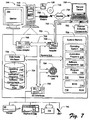
- Fig. 7 is a schematic illustration of an exemplary computing device.
- techniques can utilize subscriber preference and/or location information to adjust the data broadcast content within a specific data broadcast region.
- a network management system can adjust data broadcast content on one or more data broadcasting regions in a dynamic fashion in response to changes in the distribution of subscriber preferences in the region.
- Fig. 1 is a schematic illustration of an exemplary implementation of a data broadcasting environment 100 in which the subject matter described herein may be implemented. It will be appreciated that the environment 100 depicted in Fig. 1 is merely an exemplary environment and is not intended to suggest any limitation as to particular uses or functionality.
- the subject matter described herein may be implemented in a wide variety of data distribution environments including, but not limited to, radio,, television, and satellite networks, digital radio systems, broadcast disk systems, publish/subscribe systems, Internet-based broadcasting systems, and the like.
- the environment 100 includes at least one head end 112 that broadcasts data throughout a broadcast region 110 to one or more receivers 114 that subscribe to a data broadcasting service transmitted from head end 112.
- broadcast and its derivatives should be construed broadly to encompass any form of modulating, coding, and/or transmitting of a communication signal across a communication medium, wired or wireless.
- subscribe should be construed broadly to encompass any form of receiving, demodulating, and/or decoding of data broadcast head end 112.
- the broadcast environment 100 includes multiple broadcast regions 110, 120, 130, each of which includes a head end 112, 122, 132.
- Each head end 112, 122, 132 broadcasts data throughout its respective broadcast region.
- Fig. 1 illustrates three separate head ends 112,122,132 defining three broadcast regions 110, 120, 130, it will be appreciated that the specific number of regions is not important, and may vary depending upon, e . g ., the geographic size of the operating environment, transmission power constraints, and interference and/or obstructions of the signal(s) broadcast from the respective head ends 112, 122, 132. Also, it will be appreciated that there need not be a one-to-one correspondence between head ends and broadcast regions.
- Head ends 112, 122, 132 further include infrastructure necessary for broadcasting a data signal.
- such infrastructure may include equipment for encoding, modulating, and transmitting or transceiving a radio frequency (RF) signal at a specific frequency (or frequencies), or in accordance with a specific multi-frequency protocol.
- RF radio frequency
- Such equipment is readily commercially available, and is known to those skilled in the art. The particular encoding, modulating, and/or transmission scheme is not important.
- the broadcast environment 100 further includes a plurality of receivers 114, 124, 134, which may be embodied as wireless communication devices such as, e . g ., personal computers (PCs), laptop computers, personal digital assistants (PDAs), mobile phones, or the like.
- receivers 114, 124, 134 include an uplink communication system that enables a server to determine location information associated with the receivers 114, 124, 134. The location information does not need to precisely define the location of the user. In one implementation the location information simply indicates the current head end 112, 122, 132 providing service to a given receiver.
- each receiver 114, 124, 134 includes an identifier that uniquely identifies the receiver from all other receivers in the system.
- the unique identifier may be transmitted from the receiver 114, 124, 134 to the respective head end 112, 122, 132 providing service to the receiver, e . g ., on a control channel or on a data channel.
- Such transmissions could make use of SMS notifications, or small IP messages sent from the client's device to a database using traditional two-way wireless communication systems (e.g ., GSM/CDMA).
- each head end 112, 122, 132 is assigned a unique identifier within broadcast environment 100.
- a head end 112, 122, 132 may be identified by a network address, station name, a carrier frequency, or other distinct designation.
- a data broadcast from a head end 112, 122, 132 to a receiver 114, 124, 134 takes place over a communication channel.
- the communication channel(s) may be defined by modulating a carrier wave in accordance with any conventional RF broadcasting technique such as, e . g ., TDMA, FDMA, CDMA, or the like.
- the transmitted content may include various forms of data including, e . g ., text, audio, video, and may also include control signals including, e . g ., timing signals, power signals, location signals, etc. Control signals may be broadcast in-band, or on a separate control channel.
- Broadcast environment 100 further includes a broadcast center 140 for managing the broadcast operations of one or more head ends 112, 122, 132, and a management center 150 for managing subscriber profile information and other network management information.
- Broadcast center 140 includes a broadcast manager 142 and a broadcast data store 144.
- Management center 150 includes a subscriber profile manager 152 and a subscriber data profile 154.
- the broadcast center 140 cooperates with the management center 150 to manage subscriber information, network information, and data broadcasting from one or more of the respective head ends 112, 122, 132 of the operating environment 100.
- broadcast center 140 and management center 150 may reside on a single computing device such as, e.g., a server computer associated with broadcasting environment 100.
- the responsibility for broadcast management and subscriber profile management may be distributed between the head ends and the management center 150 in a different manner, or may be consolidated in either the management center 150 or the head ends 112, 122, 132.
- the environment 100 may include a single management center 150, but each head end 112, 122, 132 may include a broadcast center 140.
- the respective head ends 112, 122, 132 cooperate with the management center 150 to implement a data broadcast network that may cover a geographic region ranging in size from a region as small as a specific building or a corporate or academic campus to a region as large an entire couatry or continent.
- the head ends 112, 122, 132 cooperate with the management center 150 to manage subscriber information, network information, and data broadcasting.
- Fig. 2 is a schematic illustration of an exemplary computer system 200 adapted to include a broadcast center 140 and a management center 150.
- This computer system 200 includes a display 202 having a screen 204, one or more user-input devices 206, and a computer 208.
- the user-input devices 206 can include any device allowing a computer to receive a developer's input, such as a keyboard 210, other device(s) 212, and a mouse 214.
- the other device(s) 212 can include a touch screen, a voice-activated input device, a track ball, and any other device that allows the system 200 to receive input from a developer.
- the computer 208 includes a processing unit 216 and random access memory and/or read-only memory 218.
- Memory 218 includes an operating system 220 for managing operations of computer 208.
- one or more application programs executable on the processing unit 216 reside in memory 218, including a profile manager 222 and a broadcast manager 224.
- Memory 218 further includes one or more data files including user profile data files 228 and data broadcast files 230. Operation of the system 200 is explained in greater detail below.
- Fig. 3 is an illustration of an exemplary data structure for subscriber profile information.
- a subscriber to the data broadcasting system maintains a subscriber profile including a subscriber identity and specifying particular categories of information of interest to the subscriber.
- This information may be stored in a suitable memory location such as, e.g ., the user profile data files 228 stored in the memory 218 of computer 208.
- the file may be embodied as, e.g ., a relational database.
- the subscriber profile information may also be stored in the memory 318 of the data broadcasting receiver, e . g ., in the user profile data files 328.
- the subscriber profile information data structure includes a subscriber ID data field 300 and one or more categories of information of interest.
- the categories of interest include sports 310, finance 320, business 330, and entertainment 340.
- Each category may include sub-categories specifying in further detail information of interest to the subscriber identified by subscriber ID 300.
- the sports category 300 includes a soccer sub-category 312 and a baseball sub-category 314.
- the finance category 320 includes a stock quotes sub-category 322 and a mortgage rates sub-category 324.
- the business category 330 includes a weekly update sub-category 332, and the entertainment category includes a new hits sub-category 342 and a fallen stars sub-category 344.
- the data structure depicted in Fig. 3 may be expanded to include additional layers of sub-categories further detailing information of interest to a subscriber.
- the soccer sub-category 312 may be expanded to include information about one or more specific teams or the stock quotes category 342 may be expanded to include information about one or more specific stocks.
- the subscriber profile information data structure may include other specific personal information or links to other specific personal information such as, e.g ., electronic mail, electronic calendars, etc.
- the subscriber profiles may be specific to the respective broadcast region 110, 120, 130 in which the subscriber device is operating.
- a subscriber may be interested in a particular set of information when the subscriber is in broadcast region 110 and a different set of information when the subscriber is in broadcast region 130.
- the subscriber profile may be modified to include a data broadcast region indicator and corresponding data of interest for the particular broadcast region(s).
- Fig. 4 is an illustration of a data structure representing a data broadcasting schedule 400 for data broadcasting system 100.
- the data broadcasting schedule 400 may be stored in the broadcast data store 144, e . g ., as one of the broadcast data files 230 stored in the memory 218 of computer 208.
- the data broadcasting schedule 400 may be represented in tabular format as a series of documents 410 for broadcast, each of which is identified by a content identifier 420 that describes the content of the document.
- the broadcast schedule 400 further includes a broadcast periodicity 530 associated with the document that defines the periodicity with which the document is broadcast.
- the broadcast schedule further includes a start time 440 and a stop time 450 for each document.
- the broadcast schedule depicted in Fig. 5 reflects that document number 1 in the broadcast schedule includes soccer information, and is broadcast every sixty minutes beginning at 06:00:00 and terminating at 06:05:00.
- the data broadcast manager 224 maintains the data broadcast schedule 400.
- the data broadcast manager 224 may include a user interface that permits a user to add documents to or delete documents from the data broadcast schedule 400, and/or to modify the periodicity with which documents are broadcast.
- the broadcast duration is a function of the amount of data to be broadcast and the bandwidth available to the data broadcasting system 100.
- the broadcast manager 224 may update the start time 440 and stop time 450 to reflect the next broadcast of the document.
- the data broadcast files 230 may also include the content to be broadcast.
- the soccer document may include scores and other information about soccer teams
- the stock quotes may document may include current quotes for particular stocks. This information may be updated periodically by the data broadcast manager 224 or by another application program executing on the processing unit 216 of computer 208.
- the broadcast manager retrieves the document from the data broadcast files 230 and broadcast the document over from one or more head ends 112, 122, 132 in the system 100.
- the broadcast schedule may be specific to each head end 112, 122, 132, such that the broadcast schedule is different in each broadcast region 110, 120, 122.
- the broadcast manager(s) 224 cooperate with the profile manager(s) 222 to manage the data broadcast in each broadcast region 110, 120, 130 in an intelligent manner which reflects the aggregate interests of the subscribers in the broadcast region.
- Fig. 5 is a flowchart illustrating operations in an exemplary method for intelligent data broadcasting.
- the operations of Fig. 5 may be implemented by the data broadcast manager 224 of computer 208.
- certain of the operations may be performed by the profile manager module 222 of computer 208.
- the broadcast manager and the profile manager may be centrally located in a single computer.
- each head end 112, 122, 132 may maintain an independent broadcast manager and/or profile manager, which may communicate as necessary to implement intelligent broadcast operations.
- the broadcast manager 224 establishes initial broadcast parameters which may be reflected, e.g ., in a broadcast schedule such as broadcast schedule 400.
- the initial broadcast parameters may by allocated, in part, in a manner that reflects the aggregate user profile data for a broadcast region 110, 120, 130.
- mortgage rates may be allocated a relatively frequent rate of recurrence for data broadcasting, e . g ., every sixty minutes.
- the initial broadcast parameter may be set without regard to the interests expressed in the subscriber profiles.
- the broadcast manager 224 initiates the broadcast.
- the subscriber profiles for the broadcast region 110, 120, 130 are monitored for changes. This monitoring operation may be performed by either the broadcast manager 224 or by the profile manager 222. If no changes are detected, then the broadcast schedule continues unaffected.
- receivers 114, 124, 134 include a thin uplink communication system that enables a server to determine location information associated with the receivers 114, 124, 134.
- the location information does not need to precisely define the location of the user.
- the location information simply indicates which head end 112, 122, 132 is currently providing service to a given receiver.
- each receiver 114, 124, 134 includes an identifier that uniquely identifies the receiver from all other receivers in the system.
- the unique identifier may be transmitted from the receiver 114, 124, 134 to the respective head end 112, 122, 132 providing service to the receiver, e . g ., on a control channel or on a data channel.
- Such transmissions could make use of SMS notifications, small IP messages sent from the client's device to a database using traditional two way wireless communication systems (e.g., GSM/CDMA), or another messaging protocol.
- more sopbisticated locating techniques may be applied. These alternate techniques may be particularly useful when a receiver is within range of two or more head ends 112, 122, 132.
- signals from a receiver 114, 124, 134 received in two different head ends 112, 122, 132 may be used to determine location information.
- the strength of the signals received at two different head ends 112, 122, 132 may be compared to determine which of the two head ends is receiving a stronger signal, and the head end with the strongest signal may modify its broadcast schedule to reflect the addition of the subscriber to the broadcast region, This technique may be applied to any number of head ends 112, 122, 132.
- signals from a receiver 114, 124, 134 received by three separate head ends 112, 122, 132 may be used to precisely locate a receiver using conventional triangulation techniques.
- the particular location technique applied is not critical.
- Fig. 6 is a flowchart illustrating operations in an exemplary method for adjusting the broadcast schedule, as described in connection with operation 535.
- the operations of Fig. 6 may be invoked every time there is a profile change for in a broadcast region 110, 120, 130.
- the operations of Fig. 6 may be perfonned on a periodic basis or based on one or more events, i . e ., if a predetermined number of threshold changes have occurred.
- the change in demand for one or more documents is determined.
- this operation may be performed by comparing the number of subscriber units in the profile region that include a particular document in their profile information at the current point in time with a corresponding number of subscriber units at a previous point in time.
- Statistical techniques such as, e.g. , rolling averages may optionally be used to smooth measurement variations over time.
- Operation 615 is an optional thresholding operation. If, at operation 615, the change in demand for one or more documents is not greater than a threshold, then the change in demand for the document(s) may be ignored and control passes to operation 610 to examine the change in demand for another document in the broadcast carousel.
- the demand may be determined by calculating the proportion of subscriber units in a particular broadcast region that include a document in their respective user profile.
- the subscriber profiles may include an entry that indicates the frequency with which a subscriber would like to have the information in this document refreshed, i.e., a desired refresh rate, and the desired refresh rate may be incorporated into the demand calculation.
- the operations 610-625 may be repeated until there are no further documents to process.
- the broadcast carousel time slots are allocated.
- the broadcast carousel time slots may be allocated in accordance with the aggregate of the demand numbers calculated in operation 620 using, e . g ., a fairness routine or another resource allocation routine.
- a fairness routine or another resource allocation routine.
- the number of broadcast carousel time slots dedicated to the document may be doubled, subject to bandwidth limitations.
- the number of broadcast carousel time slots dedicated to the document may be reduced accordingly.
- Fig. 7 shows components of typical example of such a computer, referred by to reference numeral 700.
- the components shown in Fig. 7 are only examples, and are not intended to suggest any limitation as to the scope of the functionality of the invention; the invention is not necessarily dependent on the features shown in Fig. 7.
- various different general purpose or special purpose computing system configurations can be used.
- Examples of well known computing systems, environments, and/or configurations that may be suitable for use with the invention include, but are not limited to, personal computers, server computers, hand-held or laptop devices, multiprocessor systems, microprocessor-based systems, set top boxes, programmable consumer electronics, network PCs, minicomputers, mainframe computers, distributed computing environments that include any of the above systems or devices, and the like.
- program modules include routines, programs, objects, components, data structures, etc. that perform particular tasks or implement particular abstract data types. Tasks might also be performed by remote processing devices that are linked through a communications network.
- program modules may be located in both local and remote computer storage media.
- the instructions and/or program modules are stored at different times in the various computer-readable media that are either part of the computer or that can be read by the computer.
- Programs are typically distributed, for example, on floppy disks, CD-ROMs, DVD, or some form of communication media such as a modulated signal. From there, they are installed or loaded into the secondary memory of a computer. At execution, they are loaded at least partially into the computer's primary electronic memory.
- the invention described herein includes these and other various types of computer-readable media when such media contain instructions programs, and/or modules for implementing the steps described below in conjunction with a microprocessor or other data processors.
- the invention also includes the computer itself when programmed according to the methods and techniques described below.
- programs and other executable program components such as the operating system are illustrated herein as discrete blocks, although it is recognized that such programs and components reside at various times in different storage components of the computer, and are executed by the data processor(s) of the computer.
- the components of computer 700 may include, but are not limited to, a processing unit 704, a system memory 706, and a system bus 708 that couples various system components including the system memory to the processing unit 704.
- the system bus 708 may be any of several types of bus structures including a memory bus or memory controller, a peripheral bus, and a local bus using any of a variety of bus architectures.
- bus architectures include Industry Standard Architecture (ISA) bus, Micro Channel Architecture (MCA) bus, Enhanced ISA (EISAA) bus, Video Electronics Standards Association (VESA) local bus, and Peripheral Component Interconnect (PCI) bus also known as the Mezzanine bus.
- Computer 700 typically includes a variety of computer-readable media.
- Computer-readable media can be any available media that can be accessed by computer 700 and includes both volatile and nonvolatile media, removable and non-removable media.
- Computer-readable media may comprise computer storage media and communication media.
- Computer storage media includes volatile and nonvolatile, removable and non-removable media implemented in any method or technology for storage of information such as computer-readable instructions, data structures, program modules, or other data.
- Computer storage media includes, but is not limited to, RAM, ROM, EEPROM, flash memory or other memory technology, CD-ROM, digital versatile disks (DVD) or other optical disk storage, magnetic cassettes, magnetic tape, magnetic disk storage or other magnetic storage devices, or any other medium which can be used to store the desired information and which can be accessed by computer 700.
- Communication media typically embodies computer-readable instructions, data structures, program modules or other data in a modulated data signal such as a carrier wave or other transport mechanism and includes any information delivery media.
- modulated data signal means a signal that has one or more if its characteristics set or changed in such a manner as to encode information in the signal.
- communication media includes wired media such as a wired network or direct-wired connection and wireless media such as acoustic, RF, infrared and other wireless media. Combinations of any of the above should also be included within the scope of computer readable media.
- the system memory 706 includes computer storage media in the form of volatile and/or nonvolatile memory such as read only memory (ROM) 710 and random access memory (RAM) 712.
- ROM read only memory
- RAM random access memory
- BIOS basic input/output system
- RAM 712 typically contains data and/or program modules that are immediately accessible to and/or presently being operated on by processing unit 704.
- Fig. 7 illustrates operating system 716, application programs 718, other program modules 720, and program data 722.
- the computer 700 may also include other removable/non-removable, volatile/nonvolatile computer storage media.
- Fig. 7 illustrates a hard disk drive 724 that reads from or writes to non-removable, nonvolatile magnetic media, a magnetic disk drive 726 that reads from or writes to a removable, nonvolatile magnetic disk 728, and an optical disk drive 730 that reads from or writes to a removable, nonvolatile optical disk 732 such as a CD ROM or other optical media.
- removable/non-removable, volatile/nonvolatile computer storage media that can be used in the exemplary operating environment include, but are not limited to, magnetic tape cassettes, flash memory cards, digital versatile disks, digital video tape, solid state RAM, solid state ROM, and the like.
- the hard disk drive 724 is typically connected to the system bus 708 through a non-removable memory interface such as data media interface 734, and magnetic disk drive 726 and optical disk drive 730 are typically connected to the system bus 708 by a removable memory interface.
- Fig. 7 The drives and their associated computer storage media discussed above and illustrated in Fig. 7 provide storage of computer-readable instructions, data structures, program modules, and other data for computer 700.
- hard disk drive 724 is illustrated as storing operating system 716', application programs 718', other program modules 720', and program data 722'. Note that these components can either be the same as or different from operating system 716, application programs 718, other program modules 720, and program data 722.
- Operating system 716, application programs 718, other program modules 720, and program data 722 are given different numbers here to illustrate that, at a minimum, they are different copies.
- a user may enter commands and information into the computer 700 through input devices such as a keyboard 736, a mouse, trackball, or touch pad.
- I/O input/output
- Other input devices may include a microphone, joystick, game pad, satellite dish, scanner, or the like. These and other input devices are often connected to the processing unit 704 through an input/output (I/O) interface 742 that is coupled to the system bus, but may be connected by other interface and bus structures, such as a parallel port, game port, or a universal serial bus (USB).
- I/O input/output
- a monitor 744 or other type of display device is also connected to the system bus 708 via an interface, such as a video adapter 746.
- computers may also include other peripheral output devices (e,g ., speakers) and one or more printers, which may be connected through the I/O interface 742.
- the computer may operate in a networked environment using logical connections to one or more remote computers, such as a remote computing device 750.
- the remote computing device 750 may be a personal computer, a server, a router, a network PC, a peer device or other common network node, and typically includes many or all of the elements described above relative to computer 700.
- the logical connections depicted in Fig. 7 include a local area network (LAN) 752 and a wide area network (WAN) 754.
- LAN local area network
- WAN wide area network
- the WAN 754 shown in Fig. 7 is the Internet, the WAN 754 may also include other networks.
- Such networking environments are commonplace in offices, enterprise-wide computer networks, intranets, and the like.
- the computer 700 When used in a LAN networking environment, the computer 700 is connected to the LAN 752 through a network interface or adapter 756. When used in a WAN networking environment, the computer 700 typically includes a modem 758 or other means for establishing communications over the Internet 754.
- the modem 758 which may be internal or external, may be connected to the system bus 708 via the I/O interface 742, or other appropriate mechanism.
- program modules depicted relative to the computer 700, or portions thereof may be stored in the remote computing device 750.
- Fig. 7 illustrates remote application programs 760 as residing on remote computing device 750. It will be appreciated that the network connections shown are exemplary and other means of establishing a communications link between the computers may be used.
Landscapes
- Engineering & Computer Science (AREA)
- Signal Processing (AREA)
- Mobile Radio Communication Systems (AREA)
- Data Exchanges In Wide-Area Networks (AREA)
- Two-Way Televisions, Distribution Of Moving Picture Or The Like (AREA)
- Circuits Of Receivers In General (AREA)
Applications Claiming Priority (1)
| Application Number | Priority Date | Filing Date | Title |
|---|---|---|---|
| US10/899,929 US7580668B2 (en) | 2004-07-27 | 2004-07-27 | Intelligent data broadcasting |
Publications (2)
| Publication Number | Publication Date |
|---|---|
| EP1622293A2 true EP1622293A2 (de) | 2006-02-01 |
| EP1622293A3 EP1622293A3 (de) | 2010-09-08 |
Family
ID=35219694
Family Applications (1)
| Application Number | Title | Priority Date | Filing Date |
|---|---|---|---|
| EP05014110A Withdrawn EP1622293A3 (de) | 2004-07-27 | 2005-06-29 | Intelligenter Datenrundfunk |
Country Status (5)
| Country | Link |
|---|---|
| US (1) | US7580668B2 (de) |
| EP (1) | EP1622293A3 (de) |
| JP (1) | JP4837954B2 (de) |
| KR (1) | KR101153088B1 (de) |
| CN (1) | CN1728614B (de) |
Cited By (3)
| Publication number | Priority date | Publication date | Assignee | Title |
|---|---|---|---|---|
| WO2009021529A1 (en) * | 2007-08-10 | 2009-02-19 | Nec Europe Ltd. | Method for gathering and providing aggregated information on a group of users of a specific service |
| GB2449783B (en) * | 2006-01-03 | 2011-06-15 | Apple Inc | Media data exchange, transfer or delivery for portable electronic devices |
| US9747248B2 (en) | 2006-06-20 | 2017-08-29 | Apple Inc. | Wireless communication system |
Families Citing this family (37)
| Publication number | Priority date | Publication date | Assignee | Title |
|---|---|---|---|---|
| US6934812B1 (en) * | 2001-10-22 | 2005-08-23 | Apple Computer, Inc. | Media player with instant play capability |
| US8151259B2 (en) * | 2006-01-03 | 2012-04-03 | Apple Inc. | Remote content updates for portable media devices |
| US20130097302A9 (en) * | 2003-10-01 | 2013-04-18 | Robert Khedouri | Audio visual player apparatus and system and method of content distribution using the same |
| US20060008256A1 (en) * | 2003-10-01 | 2006-01-12 | Khedouri Robert K | Audio visual player apparatus and system and method of content distribution using the same |
| US7554934B2 (en) * | 2004-09-01 | 2009-06-30 | Broadcom Corporation | Method and apparatus for processing location service messages in a satellite position location system |
| US7706637B2 (en) * | 2004-10-25 | 2010-04-27 | Apple Inc. | Host configured for interoperation with coupled portable media player device |
| US7593782B2 (en) | 2005-01-07 | 2009-09-22 | Apple Inc. | Highly portable media device |
| CA2601161A1 (en) | 2005-03-18 | 2006-09-21 | Seeker Wireless Pty Limited | Enhanced mobile location |
| DE602006017519D1 (de) * | 2005-03-18 | 2010-11-25 | Seeker Wireless Pty Ltd | Erweitertes mobillokalisierungsverfahren und -system |
| MX2007012208A (es) * | 2005-04-08 | 2008-03-14 | Seeker Wireless Pty Lilmited | Localizacion movil terrestre, mejorada. |
| US8300841B2 (en) * | 2005-06-03 | 2012-10-30 | Apple Inc. | Techniques for presenting sound effects on a portable media player |
| US7930369B2 (en) | 2005-10-19 | 2011-04-19 | Apple Inc. | Remotely configured media device |
| EP1941749A4 (de) * | 2005-10-24 | 2012-04-18 | Wavemarket Inc D B A Location Labs | Mobildienst-wartungsverwaltung |
| US8260945B2 (en) * | 2005-11-16 | 2012-09-04 | ABSi Corporation | System and method for wirelessly broadcasting content from a core for receipt by a mobile client |
| WO2007059270A2 (en) * | 2005-11-16 | 2007-05-24 | Advanced Broadband Solutions, Inc. | System and method for providing content over a network |
| US8654993B2 (en) * | 2005-12-07 | 2014-02-18 | Apple Inc. | Portable audio device providing automated control of audio volume parameters for hearing protection |
| US8706159B2 (en) * | 2006-01-03 | 2014-04-22 | Apple Inc. | Media data transfer |
| US8255640B2 (en) * | 2006-01-03 | 2012-08-28 | Apple Inc. | Media device with intelligent cache utilization |
| US20070166683A1 (en) * | 2006-01-05 | 2007-07-19 | Apple Computer, Inc. | Dynamic lyrics display for portable media devices |
| US7848527B2 (en) | 2006-02-27 | 2010-12-07 | Apple Inc. | Dynamic power management in a portable media delivery system |
| US8358273B2 (en) * | 2006-05-23 | 2013-01-22 | Apple Inc. | Portable media device with power-managed display |
| US7729791B2 (en) | 2006-09-11 | 2010-06-01 | Apple Inc. | Portable media playback device including user interface event passthrough to non-media-playback processing |
| US8341524B2 (en) * | 2006-09-11 | 2012-12-25 | Apple Inc. | Portable electronic device with local search capabilities |
| US8090130B2 (en) | 2006-09-11 | 2012-01-03 | Apple Inc. | Highly portable media devices |
| US7589629B2 (en) * | 2007-02-28 | 2009-09-15 | Apple Inc. | Event recorder for portable media device |
| CN101682435B (zh) * | 2007-06-01 | 2015-08-05 | 汤姆森特许公司 | 用于执行接收器中的功率管理的装置和方法 |
| US20090063652A1 (en) * | 2007-09-04 | 2009-03-05 | Yoon Sub Hwang | Localized Media Content Delivery |
| WO2009036497A1 (en) | 2007-09-17 | 2009-03-26 | Seeker Wireless Pty Limited | Systems and methods for triggering location based voice and/or data communications to or from mobile radio terminals |
| WO2009067766A1 (en) | 2007-11-26 | 2009-06-04 | Seeker Wireless Pty Limited | Methods and systems for zone creation and adaption |
| EP2269390A4 (de) | 2008-04-07 | 2012-04-04 | Wavemarket Inc D B A Location Labs | Ortung von drahtlosen mobilen endgeräten |
| EP2312844B1 (de) * | 2008-08-07 | 2014-09-03 | Fujitsu Limited | Datenausstrahlungssystem, datenausstrahlungsserver und datenausstrahlungsprogramm |
| US8244236B2 (en) | 2010-04-29 | 2012-08-14 | Wavemarket, Inc. | System and method for aggregating and disseminating mobile device tag data |
| US8303410B2 (en) * | 2010-11-20 | 2012-11-06 | Telenav, Inc. | Navigation system having preference region adjustment mechanism and method of operation thereof |
| US8504077B2 (en) | 2010-12-04 | 2013-08-06 | Wavemarket, Inc. | System and method for monitoring and disseminating mobile device location information |
| JP5826585B2 (ja) * | 2011-10-17 | 2015-12-02 | 日本無線株式会社 | 無線基地局 |
| US9166159B2 (en) | 2013-05-23 | 2015-10-20 | Micron Technology, Inc. | Semiconductor constructions and methods of forming memory cells |
| US10743147B2 (en) | 2017-10-30 | 2020-08-11 | Apple Inc. | Expanded implementation of enhanced broadcast multicast services for broadcast multicast content selection and service |
Citations (2)
| Publication number | Priority date | Publication date | Assignee | Title |
|---|---|---|---|---|
| EP0920208A1 (de) | 1992-12-09 | 1999-06-02 | Discovery Communications, Inc. | Verfahren und Gerät zur Erfassung von Programmeinschaltdaten |
| WO2000054201A2 (en) | 1999-03-09 | 2000-09-14 | Netzero, Inc. | Dynamic ad targeting by an internet server |
Family Cites Families (15)
| Publication number | Priority date | Publication date | Assignee | Title |
|---|---|---|---|---|
| JP3131564B2 (ja) * | 1996-07-03 | 2001-02-05 | 松下電器産業株式会社 | 放送システム、サービス提供装置及び受信端末装置 |
| GB9822022D0 (en) * | 1998-10-09 | 1998-12-02 | Roke Manor Research | Method and apparatus for receiving a media broadcast |
| JP2002537732A (ja) * | 1999-02-17 | 2002-11-05 | インデックス システムズ インコーポレイテッド | 広告のようなテレビおよび/または電子的番組ガイド機能を調整するシステムおよび方法 |
| US6366298B1 (en) | 1999-06-03 | 2002-04-02 | Netzero, Inc. | Monitoring of individual internet usage |
| US6560777B2 (en) | 1999-04-07 | 2003-05-06 | Webtv Networks, Inc. | Broadcast enhancement trigger addressed to multiple uniquely addressed information resources |
| US6681114B2 (en) * | 2000-12-06 | 2004-01-20 | At&T Corp. | On demand multicast messaging system |
| US6463265B1 (en) | 2001-06-05 | 2002-10-08 | International Business Machines Corp. | Data source hand-off in a broadcast-based data dissemination environment |
| US7305011B2 (en) | 2001-06-14 | 2007-12-04 | International Business Machines Corporation | Periodic broadcast and location of evolving media content with application to seminar and stroke media |
| US6868264B2 (en) | 2001-12-13 | 2005-03-15 | International Business Machines Corporation | Method and apparatus for managing audio broadcasts in an automobile |
| US7133502B2 (en) * | 2002-01-31 | 2006-11-07 | Hewlett-Packard Development Company, Lp. | System for and method for dispatching service messages over a multicast network |
| US20030163528A1 (en) | 2002-02-27 | 2003-08-28 | International Business Machines Corporation | Multicasting system and method for providing personalized content |
| US20050257242A1 (en) * | 2003-03-14 | 2005-11-17 | Starz Entertainment Group Llc | Multicast video edit control |
| US20050063409A1 (en) * | 2003-09-18 | 2005-03-24 | Nokia Corporation | Method and apparatus for managing multicast delivery to mobile devices involving a plurality of different networks |
| US7415241B2 (en) * | 2004-06-02 | 2008-08-19 | Motorola, Inc. | Method and apparatus for regulating a delivery of a broadcast-multicast service in a packet data communication system |
| US8141118B2 (en) * | 2004-07-26 | 2012-03-20 | Microsoft Corporation | Data broadcasting receiver power management |
-
2004
- 2004-07-27 US US10/899,929 patent/US7580668B2/en not_active Expired - Fee Related
-
2005
- 2005-06-29 EP EP05014110A patent/EP1622293A3/de not_active Withdrawn
- 2005-07-25 CN CN200510088196.5A patent/CN1728614B/zh not_active Expired - Fee Related
- 2005-07-26 KR KR1020050067891A patent/KR101153088B1/ko not_active Expired - Fee Related
- 2005-07-27 JP JP2005217238A patent/JP4837954B2/ja not_active Expired - Fee Related
Patent Citations (2)
| Publication number | Priority date | Publication date | Assignee | Title |
|---|---|---|---|---|
| EP0920208A1 (de) | 1992-12-09 | 1999-06-02 | Discovery Communications, Inc. | Verfahren und Gerät zur Erfassung von Programmeinschaltdaten |
| WO2000054201A2 (en) | 1999-03-09 | 2000-09-14 | Netzero, Inc. | Dynamic ad targeting by an internet server |
Cited By (5)
| Publication number | Priority date | Publication date | Assignee | Title |
|---|---|---|---|---|
| US9084089B2 (en) | 2003-04-25 | 2015-07-14 | Apple Inc. | Media data exchange transfer or delivery for portable electronic devices |
| GB2449783B (en) * | 2006-01-03 | 2011-06-15 | Apple Inc | Media data exchange, transfer or delivery for portable electronic devices |
| US8694024B2 (en) | 2006-01-03 | 2014-04-08 | Apple Inc. | Media data exchange, transfer or delivery for portable electronic devices |
| US9747248B2 (en) | 2006-06-20 | 2017-08-29 | Apple Inc. | Wireless communication system |
| WO2009021529A1 (en) * | 2007-08-10 | 2009-02-19 | Nec Europe Ltd. | Method for gathering and providing aggregated information on a group of users of a specific service |
Also Published As
| Publication number | Publication date |
|---|---|
| US20060025068A1 (en) | 2006-02-02 |
| KR101153088B1 (ko) | 2012-06-04 |
| JP2006042359A (ja) | 2006-02-09 |
| EP1622293A3 (de) | 2010-09-08 |
| US7580668B2 (en) | 2009-08-25 |
| KR20060046790A (ko) | 2006-05-17 |
| JP4837954B2 (ja) | 2011-12-14 |
| CN1728614A (zh) | 2006-02-01 |
| CN1728614B (zh) | 2012-05-16 |
Similar Documents
| Publication | Publication Date | Title |
|---|---|---|
| US7580668B2 (en) | Intelligent data broadcasting | |
| EP1622278B1 (de) | Energieverbrauchsoptimierung eines Datenrundfunkempfangssystems | |
| US7653018B2 (en) | Differential update for data broadcasting | |
| US9258846B2 (en) | Automatic quality of service based resource allocation | |
| US7860002B2 (en) | Priority-based admission control in a network with variable channel data rates | |
| US11889542B2 (en) | Systems and methods for identifying wireless channels | |
| WO2021127439A1 (en) | Dynamic content insertion on a user-by-user basis | |
| CN109348264B (zh) | 视频资源共享方法、装置、存储介质及电子设备 | |
| CN102761572A (zh) | 动态调整数据流量的方法及系统 | |
| US20250392964A1 (en) | Gateway Management | |
| CN110460879B (zh) | 一种视频请求调度方法、装置、服务器及存储介质 | |
| CN109089246B (zh) | 数据传输方法及相关产品 | |
| CN109086813B (zh) | 主播相似度的确定方法、装置、设备及存储介质 | |
| CN111191134B (zh) | 一种智能推送方法及终端 | |
| CN115696614A (zh) | 一种用于海上通信中断的基站数据续传方法、系统及存储介质 | |
| CN112929432A (zh) | 一种基于重复广播历史的广播方法、设备及储存介质 | |
| CN111724208B (zh) | 一种数据发送方法、装置、设备和系统 | |
| CN118921342A (zh) | 用于将消息传送至一个或多个接收终端的方法及系统 | |
| CN120455735A (zh) | 多媒体资源的传输方法、装置、设备及介质 | |
| JP2004253973A (ja) | コンテンツ配信装置,コンテンツ受信端末,コンテンツ配信方法 |
Legal Events
| Date | Code | Title | Description |
|---|---|---|---|
| PUAI | Public reference made under article 153(3) epc to a published international application that has entered the european phase |
Free format text: ORIGINAL CODE: 0009012 |
|
| AK | Designated contracting states |
Kind code of ref document: A2 Designated state(s): AT BE BG CH CY CZ DE DK EE ES FI FR GB GR HU IE IS IT LI LT LU MC NL PL PT RO SE SI SK TR |
|
| AX | Request for extension of the european patent |
Extension state: AL BA HR LV MK YU |
|
| PUAL | Search report despatched |
Free format text: ORIGINAL CODE: 0009013 |
|
| AK | Designated contracting states |
Kind code of ref document: A3 Designated state(s): AT BE BG CH CY CZ DE DK EE ES FI FR GB GR HU IE IS IT LI LT LU MC NL PL PT RO SE SI SK TR |
|
| AX | Request for extension of the european patent |
Extension state: AL BA HR LV MK YU |
|
| 17P | Request for examination filed |
Effective date: 20110209 |
|
| AKX | Designation fees paid |
Designated state(s): AT BE BG CH CY CZ DE DK EE ES FI FR GB GR HU IE IS IT LI LT LU MC NL PL PT RO SE SI SK TR |
|
| 17Q | First examination report despatched |
Effective date: 20110429 |
|
| STAA | Information on the status of an ep patent application or granted ep patent |
Free format text: STATUS: THE APPLICATION IS DEEMED TO BE WITHDRAWN |
|
| RAP1 | Party data changed (applicant data changed or rights of an application transferred) |
Owner name: MICROSOFT TECHNOLOGY LICENSING, LLC |
|
| 18D | Application deemed to be withdrawn |
Effective date: 20141028 |
|
| REG | Reference to a national code |
Ref country code: DE Ref legal event code: R079 Free format text: PREVIOUS MAIN CLASS: H04H0009000000 Ipc: H04H0020000000 |
|
| REG | Reference to a national code |
Ref country code: DE Ref legal event code: R079 Free format text: PREVIOUS MAIN CLASS: H04H0009000000 Ipc: H04H0020000000 Effective date: 20150408 |