EP1622156A2 - Disk storage unit - Google Patents
Disk storage unit Download PDFInfo
- Publication number
- EP1622156A2 EP1622156A2 EP05014848A EP05014848A EP1622156A2 EP 1622156 A2 EP1622156 A2 EP 1622156A2 EP 05014848 A EP05014848 A EP 05014848A EP 05014848 A EP05014848 A EP 05014848A EP 1622156 A2 EP1622156 A2 EP 1622156A2
- Authority
- EP
- European Patent Office
- Prior art keywords
- case
- disk
- storage unit
- protective sleeve
- protective sleeves
- Prior art date
- Legal status (The legal status is an assumption and is not a legal conclusion. Google has not performed a legal analysis and makes no representation as to the accuracy of the status listed.)
- Withdrawn
Links
Images




Classifications
-
- G—PHYSICS
- G11—INFORMATION STORAGE
- G11B—INFORMATION STORAGE BASED ON RELATIVE MOVEMENT BETWEEN RECORD CARRIER AND TRANSDUCER
- G11B33/00—Constructional parts, details or accessories not provided for in the other groups of this subclass
- G11B33/02—Cabinets; Cases; Stands; Disposition of apparatus therein or thereon
- G11B33/04—Cabinets; Cases; Stands; Disposition of apparatus therein or thereon modified to store record carriers
- G11B33/0405—Cabinets; Cases; Stands; Disposition of apparatus therein or thereon modified to store record carriers for storing discs
- G11B33/0433—Multiple disc containers
- G11B33/0444—Multiple disc containers for discs without cartridge
Definitions
- the present invention relates to a disk storage unit, and particularly to a disk storage unit for storing recording media disks, such as CD's and DVD's.
- a conventional CD storage case which is commonly in use comprises: a case main body, of which the entirety of one side is an open surface, for storing a disk; and a lid, which is linked to the case main body by a hinge so as to open and close the open surface.
- a circular disk clamper for elastically engaging a central aperture of the disk to detachably hold the disk, is provided at the central portion of the inner surface of the case main body.
- pluralities of disks are stored in sheet-like protective sleeves made of nonwoven cloth, paper, plastic and the like, which are then stored within a single case. Thereby, space is saved and the cost of the case is reduced. However, if the number of disks further increases, the presence of the case becomes a barrier to space efficiency.
- the present invention has been developed in view of the above circumstances. It is an object of the present invention to provide a disk storage unit, which is capable of storing a great number of disks within a limited space.
- the disk storage unit of the present invention comprises:
- the manner in which the protective sleeves are removably attached to the case may be by: adhesive, which is capable of being peeled off; tearable perforations provided in the protective sleeves; or in a manner such that the protective sleeves can be cut away with scissors.
- An opening may be provided from the edge of each protective sleeve to the central portion of a disk stored therein. In this case, it is preferable that the opening extends diagonally from the corner of the protective sleeve.
- the plurality of protective sleeves are stored within the case in a removable manner. Therefore, in the case that the number of disks increases, the disks can be removed from the case along with the protective sleeves and organized in a filing implement. Thereby, storage of a great number of disks in a limited space is enabled, as well as organization and filing of the disks according to users' tastes.
- An opening may be provided from the edge of each protective sleeve to the central portion of a disk stored therein. In this case, removal of the disks from the protective sleeves is facilitated.
- Figure 1 is a perspective view of an embodiment of the disk storage unit of the present invention, in a closed state.
- Figure 2 is a plan view of a protective sleeve, which is stored within a case illustrated in Figure 1, holding a disk therein.
- Figure 3 is a plan view that illustrates the state in which the disk is removed from the protective sleeve of Figure 2.
- Figure 4 is a perspective view of the disk storage unit of Figure 1, in an open state.
- the disk storage unit U comprises a case 1, constituted by: a substantially square case main body 2; and a lid 4, which is linked to an edge of the case main body 2 via a spine portion 3 so as to be openable and closable.
- the inner surface of the spine portion 3 forms a protective sleeve attaching portion 5 (refer to Figure 4).
- the two substantially parallel edges of the spine portion 3 constitute hinges of the case main body 2 and the lid 4.
- a plurality of sheet-like protective sleeves 11, such as that illustrated in Figure 2, each storing a disk 10 therein, are housed within the case 1.
- the protective sleeves 11 storing the disks 10 therein are formed as substantially square sheets of nonwoven cloth.
- Each protective sleeve 11 comprises: an upper edge 11a, a side edge 11b, in which apertures 15, 15 to be described later are provided, a side edge 11c opposite the side edge 11b, and a lower edge.
- a linear cut 12a that extends toward the center of the protective sleeve 11 from the vicinity of the upper edge 11a and the side edge 11b is formed in the front side of the protective sleeve 11.
- a cut 12b that extends from the tip of the cut 12a to the side edge 11c in a line substantially parallel to the upper edge 11a is formed continuously with the cut 12a. Further, the upper portion of the side edge 11c is cut open.
- An upwardly opening trap door lid 13 that exposes the upper portion of the disk 10 is formed by the cuts 12a, 12b, and the cut open upper portion of the side edge 11c.
- the trap door lid 13 is opened by bending along a bend line L, which is parallel to the upper edge 11a.
- a narrow band-like region 14 is formed between the upper edge 11a of the protective sleeve 11 and the bend line L. The band-like region 14 slightly overlaps the upper end of the disk 10.
- the trap door lid 13 When removing the disk 10 from the protective sleeve 11, first, the trap door lid 13 is opened as illustrated in Figure 3. Next, the lid 13 is pulled upward and backward toward the rear side of the protective sleeve 11, to move the region 14 from the front side of the disk 10 to the rear side thereof, thereby exposing the upper end of the disk 10. Then, the upper end of the disk 10 is gripped with fingers and pulled diagonally upward toward the right, in the direction of arrow A of Figure 3. That is, the disk 10 is pulled toward the corner between the upper edge 11a and the side edge 11c, to remove the disk 10 from the protective sleeve 11.
- Two apertures 15, 15 are formed in the vicinity of the side edge 11b, with a predetermined interval therebetween.
- the apertures 15, 15 enable the protective sleeve 11 to be filed in a binding filing implement (binder).
- the side edge 11b is attached to the protective sleeve attaching portion 5 at the inner surface of the spine portion 3 via an adhesive, as illustrated in Figure 4.
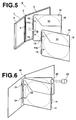
- the protective sleeve 11 can be removed from the case 1, by pulling the protective sleeve 11 in the direction indicated by arrow B of Figure 5, to peel the side edge 11b off of the protective sleeve attaching portion 5.
- the protective sleeve 11 which has been removed from the case 1 and which stores a disk 10 therein, can be filed into a commercially available binder 20, by feeding rings 21, 21 through the apertures 15, 15, as illustrated in Figure 6.
- commercially available labels 22 may be employed to attach tags 23 on to the protective sleeves 11.
- a plurality of protective sleeves 11 are housed within the case 1 in a removable manner.
- the protective sleeves 11 are provided with the apertures 15, which enable filing within the binder 20. Therefore, in the case that the number of disks 10 increases, the disks 10 can be removed from the case 1 along with the protective sleeves 11, and filed in the binder 20. Thereby, storage of a great number of disks 10 within a limited space is enabled. Another advantageous effect, in that classification and filing according to users' tastes is enabled, is also obtained.
- the side edge 11b of the protective sleeve 11 is removably attached to the case 1 with an adhesive.
- the side edge 11b of a protective sleeve 11' may be permanently attached to the case 1, while providing perforations 16 parallel to the side edge 11b in the vicinity thereof, as illustrated in Figure 7.
- the case 1 and the protective sleeve 11' may be separated by tearing along the perforations 16 as necessary.
- the perforations 16 need not be provided, and the portion in the vicinity of the side edge 11b may be cut with scissors or the like.
- the apertures 15, 15 are provided to enable filing of the protective sleeves 11 in the binder 20.
- the apertures 15, 15 need not be provided, and the protective sleeves 11 may be bound in a filing implement by being sandwiched therein or the like.
- Figure 8 is a plan view that illustrates an alternate embodiment of the protective sleeve.
- the front side of a protective sleeve 11" is provided with an opening 17 that extends from the corner between the side edge 11c and the upper edge 11a toward the central portion of the disk 10.
- the side edge 11c is opposite the side edge 11b which is removably attached to the case 1.
- a central aperture 10a of the disk 10 is exposed through the opening 17.
- the upper edge 11a and the side edge 11c are cut open from the edges of the opening 17 through the ranges denoted by 18a and 18c, respectively.
- This construction enables a finger to be inserted into the central aperture 10a of the disk 10, to draw the disk 10 out diagonally upward in the direction indicated by arrow C.
- a bag portion 19 having a region 19 that slightly overlaps an edge of the disk 10 may be provided at the corner between the side edge 11c and the upper edge 11a, as illustrated in Figure 9.
- the bag portion 19 can be pulled upward and backward toward the rear side of the protective sleeve 11", to move the region 19 from the front side of the disk 10 to the rear side thereof, thereby exposing the upper right end of the disk 10. Then, the disk can be drawn out in the upper right direction indicated by arrow C.
Landscapes
- Packaging For Recording Disks (AREA)
Abstract
Description
- The present invention relates to a disk storage unit, and particularly to a disk storage unit for storing recording media disks, such as CD's and DVD's.
- A conventional CD storage case which is commonly in use (hereinafter, referred to as "standard case") comprises: a case main body, of which the entirety of one side is an open surface, for storing a disk; and a lid, which is linked to the case main body by a hinge so as to open and close the open surface. A circular disk clamper, for elastically engaging a central aperture of the disk to detachably hold the disk, is provided at the central portion of the inner surface of the case main body.
- However, the standard case is capable of holding only a single disk therein. Therefore, a problem is arising in that as the number of disks increases, storage space is difficult to secure.
- In response to this problem, pluralities of disks are stored in sheet-like protective sleeves made of nonwoven cloth, paper, plastic and the like, which are then stored within a single case. Thereby, space is saved and the cost of the case is reduced. However, if the number of disks further increases, the presence of the case becomes a barrier to space efficiency.
- The present invention has been developed in view of the above circumstances. It is an object of the present invention to provide a disk storage unit, which is capable of storing a great number of disks within a limited space.
- The disk storage unit of the present invention comprises:
- a case; and
- a plurality of sheet-like protective sleeves, each for storing a disk therein; characterized by:
- each of the protective sleeves being removably attached to the case at one of the edges thereof.
- The manner in which the protective sleeves are removably attached to the case may be by: adhesive, which is capable of being peeled off; tearable perforations provided in the protective sleeves; or in a manner such that the protective sleeves can be cut away with scissors.
- An opening may be provided from the edge of each protective sleeve to the central portion of a disk stored therein. In this case, it is preferable that the opening extends diagonally from the corner of the protective sleeve.
- According to the disk storage unit of the present invention, the plurality of protective sleeves are stored within the case in a removable manner. Therefore, in the case that the number of disks increases, the disks can be removed from the case along with the protective sleeves and organized in a filing implement. Thereby, storage of a great number of disks in a limited space is enabled, as well as organization and filing of the disks according to users' tastes.
- An opening may be provided from the edge of each protective sleeve to the central portion of a disk stored therein. In this case, removal of the disks from the protective sleeves is facilitated.
-
- Figure 1 is a perspective view of an embodiment of the disk storage unit of the present invention, in a closed state.
- Figure 2 is a plan view of a protective sleeve, which is stored within a case illustrated in Figure 1, holding a disk therein.
- Figure 3 is a plan view that illustrates the state in which the disk is removed from the protective sleeve of Figure 2.
- Figure 4 is a perspective view of the disk storage unit of Figure 1, in an open state.
- Figure 5 is a perspective view that illustrates a state in which the protective sleeve is removed from the case in the state illustrated in Figure 4.
- Figure 6 is a perspective view that illustrates a state in which the protective sleeve is filed within a binder.
- Figure 7 is a plan view that illustrates an alternate embodiment of the protective sleeve.
- Figure 8 is a plan view that illustrates another alternate embodiment of the protective sleeve.
- Figure 9 is a plan view that illustrates an alternate embodiment of the protective sleeve of Figure 8.
- Figure 1 is a perspective view of an embodiment of the disk storage unit of the present invention, in a closed state. Figure 2 is a plan view of a protective sleeve, which is stored within a case illustrated in Figure 1, holding a disk therein. Figure 3 is a plan view that illustrates the state in which the disk is removed from the protective sleeve of Figure 2. Figure 4 is a perspective view of the disk storage unit of Figure 1, in an open state.
- As illustrated in Figure 1 and Figure 4, the disk storage unit U comprises a
case 1, constituted by: a substantially square casemain body 2; and alid 4, which is linked to an edge of the casemain body 2 via aspine portion 3 so as to be openable and closable. The inner surface of thespine portion 3 forms a protective sleeve attaching portion 5 (refer to Figure 4). The two substantially parallel edges of thespine portion 3 constitute hinges of the casemain body 2 and thelid 4. A plurality of sheet-likeprotective sleeves 11, such as that illustrated in Figure 2, each storing adisk 10 therein, are housed within thecase 1. - The
protective sleeves 11 storing thedisks 10 therein are formed as substantially square sheets of nonwoven cloth. Eachprotective sleeve 11 comprises: anupper edge 11a, aside edge 11b, in whichapertures side edge 11c opposite theside edge 11b, and a lower edge. - A
linear cut 12a that extends toward the center of theprotective sleeve 11 from the vicinity of theupper edge 11a and theside edge 11b is formed in the front side of theprotective sleeve 11. Acut 12b that extends from the tip of thecut 12a to theside edge 11c in a line substantially parallel to theupper edge 11a is formed continuously with thecut 12a. Further, the upper portion of theside edge 11c is cut open. An upwardly openingtrap door lid 13 that exposes the upper portion of thedisk 10 is formed by thecuts side edge 11c. Thetrap door lid 13 is opened by bending along a bend line L, which is parallel to theupper edge 11a. A narrow band-like region 14 is formed between theupper edge 11a of theprotective sleeve 11 and the bend line L. The band-like region 14 slightly overlaps the upper end of thedisk 10. - When removing the
disk 10 from theprotective sleeve 11, first, thetrap door lid 13 is opened as illustrated in Figure 3. Next, thelid 13 is pulled upward and backward toward the rear side of theprotective sleeve 11, to move theregion 14 from the front side of thedisk 10 to the rear side thereof, thereby exposing the upper end of thedisk 10. Then, the upper end of thedisk 10 is gripped with fingers and pulled diagonally upward toward the right, in the direction of arrow A of Figure 3. That is, thedisk 10 is pulled toward the corner between theupper edge 11a and theside edge 11c, to remove thedisk 10 from theprotective sleeve 11. - Two
apertures 15, 15 (punched apertures) are formed in the vicinity of theside edge 11b, with a predetermined interval therebetween. Theapertures protective sleeve 11 to be filed in a binding filing implement (binder). Theside edge 11b is attached to the protectivesleeve attaching portion 5 at the inner surface of thespine portion 3 via an adhesive, as illustrated in Figure 4. - Accordingly, the
protective sleeve 11 can be removed from thecase 1, by pulling theprotective sleeve 11 in the direction indicated by arrow B of Figure 5, to peel theside edge 11b off of the protectivesleeve attaching portion 5. - The
protective sleeve 11, which has been removed from thecase 1 and which stores adisk 10 therein, can be filed into a commerciallyavailable binder 20, byfeeding rings apertures available labels 22 may be employed to attachtags 23 on to theprotective sleeves 11. - In this manner, according to the present embodiment, a plurality of
protective sleeves 11 are housed within thecase 1 in a removable manner. In addition, theprotective sleeves 11 are provided with theapertures 15, which enable filing within thebinder 20. Therefore, in the case that the number ofdisks 10 increases, thedisks 10 can be removed from thecase 1 along with theprotective sleeves 11, and filed in thebinder 20. Thereby, storage of a great number ofdisks 10 within a limited space is enabled. Another advantageous effect, in that classification and filing according to users' tastes is enabled, is also obtained. - Note that in the embodiment described above, the
side edge 11b of theprotective sleeve 11 is removably attached to thecase 1 with an adhesive. Alternatively, theside edge 11b of a protective sleeve 11' may be permanently attached to thecase 1, while providingperforations 16 parallel to theside edge 11b in the vicinity thereof, as illustrated in Figure 7. Thecase 1 and the protective sleeve 11' may be separated by tearing along theperforations 16 as necessary. As a further alternative, theperforations 16 need not be provided, and the portion in the vicinity of theside edge 11b may be cut with scissors or the like. - In addition, in the embodiment described above, the
apertures protective sleeves 11 in thebinder 20. However, theapertures protective sleeves 11 may be bound in a filing implement by being sandwiched therein or the like. - Figure 8 is a plan view that illustrates an alternate embodiment of the protective sleeve. The front side of a
protective sleeve 11" is provided with anopening 17 that extends from the corner between theside edge 11c and theupper edge 11a toward the central portion of thedisk 10. Theside edge 11c is opposite theside edge 11b which is removably attached to thecase 1. Acentral aperture 10a of thedisk 10 is exposed through theopening 17. In addition, theupper edge 11a and theside edge 11c are cut open from the edges of theopening 17 through the ranges denoted by 18a and 18c, respectively. This construction enables a finger to be inserted into thecentral aperture 10a of thedisk 10, to draw thedisk 10 out diagonally upward in the direction indicated by arrow C. - Note that in this case, a
bag portion 19 having aregion 19 that slightly overlaps an edge of thedisk 10 may be provided at the corner between theside edge 11c and theupper edge 11a, as illustrated in Figure 9. Thereby, inadvertent removal of thedisk 10 from theprotective sleeve 11" can be prevented. In this case also, thebag portion 19 can be pulled upward and backward toward the rear side of theprotective sleeve 11", to move theregion 19 from the front side of thedisk 10 to the rear side thereof, thereby exposing the upper right end of thedisk 10. Then, the disk can be drawn out in the upper right direction indicated by arrow C.
Claims (6)
- A disk storage unit (U), comprising:a case (1); anda plurality of sheet-like protective sleeves (11, 11', 11"), each for storing a disk (10) therein; characterized by:each of the protective sleeves (11, 11', 11") being removably attached to the case (1) at one of the edges (11b) thereof.
- A disk storage unit (U) as defined in Claim 1, wherein:the protective sleeves (11) are removably attached to the case (1) with adhesive, which is capable of being peeled off.
- A disk storage unit (U) as defined in Claim 1, wherein:the protective sleeves (11') are removably attached to the case (1) by means of tearable perforations (16) provided in the protective sleeves (11').
- A disk storage unit (U) as defined in Claim 1, wherein:the protective sleeves (11') are removably attached to the case (1) in a manner such that they may be cut away from the case (1) with scissors.
- A disk storage unit (U) as defined in Claim 1, wherein:the protective sleeves (11") are provided with openings (17) that extend from the edges thereof to the centers of the disks (10) stored therein.
- A disk storage unit (U) as defined in Claim 5, wherein:the openings (17) extend diagonally from the corners of the protective sleeves (11").
Applications Claiming Priority (1)
| Application Number | Priority Date | Filing Date | Title |
|---|---|---|---|
| JP2004218563A JP2006036276A (en) | 2004-07-27 | 2004-07-27 | Disc storing case |
Publications (2)
| Publication Number | Publication Date |
|---|---|
| EP1622156A2 true EP1622156A2 (en) | 2006-02-01 |
| EP1622156A3 EP1622156A3 (en) | 2007-12-19 |
Family
ID=35170195
Family Applications (1)
| Application Number | Title | Priority Date | Filing Date |
|---|---|---|---|
| EP05014848A Withdrawn EP1622156A3 (en) | 2004-07-27 | 2005-07-08 | Disk storage unit |
Country Status (5)
| Country | Link |
|---|---|
| US (1) | US20060021887A1 (en) |
| EP (1) | EP1622156A3 (en) |
| JP (1) | JP2006036276A (en) |
| CN (1) | CN1734645A (en) |
| TW (1) | TW200612402A (en) |
Family Cites Families (8)
| Publication number | Priority date | Publication date | Assignee | Title |
|---|---|---|---|---|
| US5513749A (en) * | 1995-05-11 | 1996-05-07 | Simmons; Charles B. | Storage case for multiple compact discs |
| US5501540A (en) * | 1995-06-01 | 1996-03-26 | Ho; Chin-Lien | Binder assembly with a loose-leaf sheet having a pouch for receiving a computer disk therein |
| US5501326A (en) * | 1995-06-26 | 1996-03-26 | Shuhsiang; Wu C. | Laser record protection folder |
| JP2964131B2 (en) * | 1996-05-27 | 1999-10-18 | 株式会社サンウ | Storage case for recording media |
| US6409013B1 (en) * | 1997-07-31 | 2002-06-25 | Ezra D. Eskandry | Compact disk case with stackable sleeves |
| US20020029987A1 (en) * | 2000-01-12 | 2002-03-14 | Shahriar Dardashti | Disc storage case |
| JP4422308B2 (en) * | 2000-08-24 | 2010-02-24 | ナカバヤシ株式会社 | Covers for albums and bookbinding methods |
| US6994215B2 (en) * | 2002-10-07 | 2006-02-07 | Hai Yang Corporation | Sleeve retainer clip for a compact disc binder |
-
2004
- 2004-07-27 JP JP2004218563A patent/JP2006036276A/en not_active Abandoned
-
2005
- 2005-07-08 EP EP05014848A patent/EP1622156A3/en not_active Withdrawn
- 2005-07-11 CN CN200510083549.2A patent/CN1734645A/en active Pending
- 2005-07-25 TW TW094125102A patent/TW200612402A/en unknown
- 2005-07-27 US US11/189,747 patent/US20060021887A1/en not_active Abandoned
Also Published As
| Publication number | Publication date |
|---|---|
| JP2006036276A (en) | 2006-02-09 |
| CN1734645A (en) | 2006-02-15 |
| TW200612402A (en) | 2006-04-16 |
| US20060021887A1 (en) | 2006-02-02 |
| EP1622156A3 (en) | 2007-12-19 |
Similar Documents
| Publication | Publication Date | Title |
|---|---|---|
| US5876145A (en) | Multiple sheets grouping device for loose leaf files | |
| EP1622156A2 (en) | Disk storage unit | |
| EP1622157A2 (en) | Disk storage unit | |
| JP2010201725A (en) | File | |
| JP2010274610A (en) | File | |
| JP3453683B1 (en) | Versatile punch | |
| JP3116936U (en) | Clear pocket | |
| JP4159807B2 (en) | Envelope cover and envelope binding tool | |
| JP3147002U (en) | File set | |
| JP3091346U (en) | Envelopes for holding CDs and binders with envelopes | |
| JP4690488B1 (en) | Holder latching tab and holder and file | |
| JP3010177B2 (en) | File book with case | |
| JP3057774U (en) | Case for disk-shaped recording media | |
| JP3033075U (en) | Compact disc storage | |
| JP3062932U (en) | Notebook cover | |
| JP3113601U (en) | Holder and filing tool | |
| JP3143790U (en) | Disc storage case | |
| JP4106760B2 (en) | Information storage medium container and booklet with information storage medium container | |
| JP3200523U (en) | Organizer with tabs | |
| JP3010513U (en) | Book signatures that store CDs as an appendix | |
| JP3003374U (en) | Cartridge holder | |
| JP2004292010A (en) | Storage case | |
| JP2004168017A (en) | Binder writable using cover as underlay | |
| AU9612998A (en) | A storage case and a holder thereof | |
| JP2004035089A (en) | Container |
Legal Events
| Date | Code | Title | Description |
|---|---|---|---|
| PUAI | Public reference made under article 153(3) epc to a published international application that has entered the european phase |
Free format text: ORIGINAL CODE: 0009012 |
|
| AK | Designated contracting states |
Kind code of ref document: A2 Designated state(s): AT BE BG CH CY CZ DE DK EE ES FI FR GB GR HU IE IS IT LI LT LU LV MC NL PL PT RO SE SI SK TR |
|
| AX | Request for extension of the european patent |
Extension state: AL BA HR MK YU |
|
| RAP1 | Party data changed (applicant data changed or rights of an application transferred) |
Owner name: FUJIFILM CORPORATION |
|
| PUAL | Search report despatched |
Free format text: ORIGINAL CODE: 0009013 |
|
| AK | Designated contracting states |
Kind code of ref document: A3 Designated state(s): AT BE BG CH CY CZ DE DK EE ES FI FR GB GR HU IE IS IT LI LT LU LV MC NL PL PT RO SE SI SK TR |
|
| AX | Request for extension of the european patent |
Extension state: AL BA HR MK YU |
|
| AKX | Designation fees paid | ||
| STAA | Information on the status of an ep patent application or granted ep patent |
Free format text: STATUS: THE APPLICATION IS DEEMED TO BE WITHDRAWN |
|
| 18D | Application deemed to be withdrawn |
Effective date: 20080620 |
|
| REG | Reference to a national code |
Ref country code: DE Ref legal event code: 8566 |