JP3147002U - File set - Google Patents
File set Download PDFInfo
- Publication number
- JP3147002U JP3147002U JP2008006804U JP2008006804U JP3147002U JP 3147002 U JP3147002 U JP 3147002U JP 2008006804 U JP2008006804 U JP 2008006804U JP 2008006804 U JP2008006804 U JP 2008006804U JP 3147002 U JP3147002 U JP 3147002U
- Authority
- JP
- Japan
- Prior art keywords
- edge
- file
- locking
- document file
- width
- Prior art date
- Legal status (The legal status is an assumption and is not a legal conclusion. Google has not performed a legal analysis and makes no representation as to the accuracy of the status listed.)
- Expired - Fee Related
Links
Images


Abstract
【課題】 既存の書類ファイルに大きな変更を加えずに、確実にバインダーに綴じることを可能としたファイルセットを提供する。
【解決手段】 可撓性と復元性を有する合成樹脂製の表側シートと裏側シートを重ね合わせ、少なくともシートの背側の端縁11とそれに隣り合う端縁12の2辺を閉塞して、表裏のシート間に書類を挟み込み可能とした書類ファイル10と、複数の書類ファイルを綴じて収容可能としたバインダー1の組み合わせからなるファイルセットにおいて、複数個の薄板状の係止片2、3をバインダーの内面から突設すると共に、書類ファイルの背側の端縁11に上記係止片を表裏のシート間に挿通して係止するための係止穴15、16を設ける。
【選択図】 図1PROBLEM TO BE SOLVED: To provide a file set that can be surely bound to a binder without greatly changing an existing document file.
A front and back sheet made of synthetic resin having flexibility and resilience is overlapped, and at least two sides of an edge 11 on the back side of the sheet and an edge 12 adjacent thereto are closed, and the front and back sides are closed. In a file set consisting of a combination of a document file 10 that allows a document to be sandwiched between sheets and a binder 1 that is capable of binding and storing a plurality of document files, a plurality of thin-plate-like locking pieces 2 and 3 are bound to a binder. And locking holes 15 and 16 are provided in the back edge 11 of the document file for inserting and locking the locking pieces between the front and back sheets.
[Selection] Figure 1
Description
この考案は、書類を挟み込んで収容するための書類ファイルと、この書類ファイルを綴じて収容可能としたバインダーの組み合わせからなるファイルセットに関する。 The present invention relates to a file set composed of a combination of a document file for holding a document in between and a binder that can be stored by binding the document file.
図21に示すように、透明または半透明の合成樹脂製のシートを2つ折りにして重ね合わせ、背折り部41に隣り合う一方の端縁42を溶着することにより、背側の端縁とそれに隣り合う端縁の2辺を閉塞し、表裏のシート40A、40B間に書類Pを挟み込み可能とした書類ファイル40が、「クリアフォルダー」、「クリアファイル」として広く使用されている(例えば特許文献1)。この種のファイルは、本来、それ単独で完結して使用することを前提としているものであり、3辺を閉塞した袋状でなく、前側の端縁と上側の端縁の2片を開放していることも相まって、ある程度の剛性を要し、比較的厚手の可撓性と復元性を有するシートにより構成される。
As shown in FIG. 21, a transparent or translucent synthetic resin sheet is folded in two and overlapped, and one
この場合、書類を収容したファイルの数が増えた場合は、それを手際よく整理しなくては収拾がつかなくなるおそれがあるので、ケースやキャビネットに入れて収容、整理するのが一般的である。 In this case, if the number of files containing documents increases, there is a risk that they will not be collected unless they are carefully organized, so it is common to store and organize them in cases and cabinets. .
一方、複数の書類ファイルをバインダーに綴じて収容する考案も提案されており、特許文献2にはバインダーのリングに綴じ込み可能な突出片を書類ファイルの背側から突設したことを特徴とする考案が、同じく特許文献3にはバインダーの内面と書類ファイルの背側端縁に雌雄の面ファスナーを設けたことを特徴とする考案が開示されている。
On the other hand, there has also been proposed a device for storing a plurality of document files by binding them in a binder.
前記の従来技術中、書類ファイルをケースやキャビネットに入れて収容する場合、確実に収容できる反面、携帯性に欠け、また、バインダーのように本棚などに収容することが困難である問題がある。 In the prior art described above, when a document file is stored in a case or cabinet, the document file can be securely stored, but it is not portable and is difficult to store in a bookshelf or the like like a binder.
次に、バインダーのリングに綴じ込み可能な突出片を書類ファイルの背側から突設する特許文献2に記載の考案は、書類ファイルをバインダーから外して単独で使用する際に突出片が邪魔になる問題がある。この場合、同文献に記載のように突出片を着脱自在とする場合は一々突出片を着脱しなくてはならない手間がかかり、また外した突出片を紛失するおそれもあった。
Next, in the device described in
次に、バインダーの内面と書類ファイルの背側端縁に雌雄の面ファスナーを設ける特許文献3の考案は、比較的多くの書類を1つの書類ファイルに挟み込んで使用することが一般的な書類ファイルの使用法に照らした場合、重量が嵩んだ場合に問題が生ずるおそれがあった。すなわち、重量が嵩んだ書類ファイルを面ファスナーをもって確実にバインダーに係着するには書類ファイルの背側端縁の面ファスナーを幅広にしなくてはならず、それに対応して書類ファイルの厚みを大きくせざるを得ず、嵩張る問題があった。
Next, the device of
また、書類ファイルをバインダーに綴じることを可能とした前記2つの考案においては、携帯性に富む反面、挟み込んだ書類が開放した2辺から携帯時に脱落するおそれがあった。 Further, in the above two devices that make it possible to bind a document file to a binder, the document file is rich in portability, but there is a possibility that the sandwiched document may be dropped from the two open sides when it is carried.
この考案は上記の従来技術の問題点に鑑みて創作されたものであり、既存の書類ファイルに大きな変更を加えずに、確実にバインダーに綴じることを可能としたファイルセットを提供することを目的する。 This invention was created in view of the above-mentioned problems of the prior art, and an object thereof is to provide a file set that can be bound to a binder without making a major change to an existing document file. To do.
即ち、この考案のファイルセットは可撓性と復元性を有する合成樹脂製の表側シートと裏側シートを重ね合わせ、少なくともシートの背側の端縁とそれに隣り合う端縁の2辺を閉塞して、表裏のシート間に書類を挟み込み可能とした書類ファイルと、複数の書類ファイルを綴じて収容可能としたバインダーの組み合わせからなるファイルセットにおいて、複数個の薄板状の係止片をバインダーの内面から突設すると共に、書類ファイルの背側の端縁に上記係止片を表裏のシート間に挿通して係止するための係止穴を設けたことを特徴とする。 That is, the file set of the present invention has a synthetic resin front side sheet and a back side sheet which are flexible and recoverable, and closes at least two sides of the back edge and the adjacent edge of the sheet. In a file set consisting of a combination of a document file that allows a document to be sandwiched between front and back sheets and a binder that can be accommodated by binding a plurality of document files, a plurality of thin plate-like locking pieces are attached from the inner surface of the binder. In addition to projecting, a locking hole for inserting and locking the locking piece between the front and back sheets is provided on the back edge of the document file.
又、ここでは第2考案として、以上のファイルセットにおいて、幅狭の首部の前方に先端に向かって収束する形状からなる幅広の顎部を連続させることにより、顎部下縁を係止段部とした薄板状の係止片と、表裏いずれかのシートに根元を残して舌片状に切り抜かれる切り抜きにして、開放した先端を書類ファイルの背側の端縁に接して配すると共に、残された根元を上記端縁より前側にオフセットして配した係止穴を有し、書類ファイルの背側の端縁に接して配される係止穴の先端の幅を係止片の首部の幅より広く、且つ顎部の幅より狭く設定すると共に、係止穴の根元の幅を係止片の顎部の幅より広く設定したファイルセットも開示する。 Further, as the second device, in the above file set, the lower jaw portion is set as the locking step portion by continuing the wide jaw portion having a shape converging toward the tip in front of the narrow neck portion. The thin plate-like locking piece and the cutout that is cut out in the form of a tongue piece leaving the root on either the front or back sheet, the open end is placed in contact with the back edge of the document file, and it is left behind The top of the locking hole is placed in contact with the back edge of the document file and the width of the neck of the locking piece. Also disclosed is a file set that is set wider and narrower than the width of the jaw, and the width of the base of the locking hole is set wider than the width of the jaw of the locking piece.
又、ここでは第3考案として、以上のファイルセットにおいて、幅狭の首部の前方に先端に向かって収束する形状からなる幅広の顎部を連続させることにより、顎部下縁を係止段部とした薄板状の係止片と、表裏いずれかのシートに貫通してして切り欠かれる穴状の切り欠きにして、先端を書類ファイルの背側の端縁に接して配すると共に、後端を上記端縁より前側にオフセットして配した係止穴を有し、書類ファイルの背側の端縁に接して配される係止穴の先端の幅を係止片の首部の幅より広く、且つ顎部の幅より狭く設定すると共に、係止穴の後端の幅を係止片の顎部の幅より広く設定した考案も開示する。 Further, as the third device, in the above file set, the lower jaw portion is made to be a locking step portion by continuing a wide jaw portion having a shape converging toward the tip in front of the narrow neck portion. The thin plate-shaped locking piece and the hole-shaped notch that penetrates through either the front or back sheet, and the leading edge is placed in contact with the back edge of the document file. Has a locking hole that is offset to the front side of the edge, and the width of the tip of the locking hole that is arranged in contact with the back edge of the document file is wider than the width of the neck of the locking piece. In addition, there is also disclosed a device in which the width of the rear end of the locking hole is set wider than the width of the jaw of the locking piece while being set narrower than the width of the jaw.
又、ここでは第4考案として、以上のファイルセットにおいて、書類ファイルの開放した辺の少なくとも一つの辺に表裏のシートの端縁同士が開くことを防止するクリップを付属させたファイルセットも開示する。 In addition, here, as the fourth device, a file set is disclosed in which a clip for preventing the edges of the front and back sheets from opening on at least one side of the open side of the document file is attached. .
以上の構成よりなるこの考案のファイルセットによれば、バインダーの内面から突設される薄板状の係止片と、書類ファイルの背側の端縁に設けられる係止穴との係止により書類ファイルをバインダーに綴じるので、書類ファイルをそれ単独で完結して使用することも、複数個を一つのバインダーに綴じて収容、整理することもでき、しかもバインダーごと携帯したり本棚に収容することも可能となる。 According to the file set of the present invention having the above-described configuration, the document is formed by locking the thin plate-like locking piece protruding from the inner surface of the binder and the locking hole provided on the back edge of the document file. Since the file is bound to the binder, the document file can be used by completing it alone, or it can be stored and organized in a single binder, and it can be carried with the binder or stored on the bookshelf. It becomes possible.
この場合、第4考案によれば書類ファイルの開放した辺に表裏のシートの端縁同士が開くことを防止するクリップを付属させるので、書類ファイルから書類が脱落することなく安心してバインダーを携帯することが可能となる。 In this case, according to the fourth device, since the clip that prevents the edges of the front and back sheets from opening to the open side of the document file is attached, the binder can be safely carried without dropping the document from the document file. It becomes possible.
一方、この考案においては可撓性と復元性を有する合成樹脂製のシートにより構成される書類ファイルがある程度の剛性を有することに着目し、背側の端縁に係止穴を設けることにより、バインダー側の係止片と係止させる構成としている。よって、書類ファイルに突部が生じたり、別部材を要することなく書類ファイルをバインダーに綴じることが可能となり、書類ファイルの既存の構成の変更は最小限で済むので、使用者に違和感を与えることなく、しかも低コストで、バインダーとそれに綴じ込み可能な書類ファイルからなるファイルセットが実現される。 On the other hand, in this device, paying attention to the fact that the document file composed of a synthetic resin sheet having flexibility and resilience has a certain degree of rigidity, by providing a locking hole on the edge on the back side, It is set as the structure made to latch with the latching piece by the side of a binder. Therefore, it is possible to bind the document file to the binder without causing a protrusion in the document file or requiring a separate member, and the change in the existing configuration of the document file can be minimized, giving the user a sense of incongruity. In addition, a file set including a binder and a document file that can be bound to the binder is realized at low cost.
この場合、第2考案によれば、シートに舌片状に切り抜かれる切り抜きをもって係止穴とし、書類ファイルの背側の端縁に位置する係止穴の先端に対し、上記端縁より前側にオフセットして位置する根元の幅を広くし、根元において係止片の顎部が通過可能としているので、裏側のシートの表面と係止穴の切り抜きにより生じる表側のシートの舌片の裏面の間から係止片を進入させて、根元において顎部を表裏のシート間に挿通した後に手前に引き戻せば、顎部下縁の係止段部が係止穴の外側の書類ファイルの背側の端縁に係止する作用が実現されることとなり、容易且つ確実な係止が可能となる。 In this case, according to the second device, a cutout that is cut out in the form of a tongue piece on the sheet is used as a lock hole, and the front end of the lock hole located at the edge on the back side of the document file is forward of the end edge. Since the width of the root located offset is widened so that the jaw of the locking piece can pass through at the root, it is between the surface of the back sheet and the back surface of the tongue of the front sheet generated by cutting out the locking hole. If the jaw is inserted between the front and back sheets at the base and then pulled back toward the front, the latching step on the lower edge of the jaw will be at the back end of the document file outside the latch hole. The action of locking to the edge is realized, and easy and reliable locking is possible.
また、第3考案によれば、シートに貫通して切り欠かれる穴状の切り欠きをもって係止穴とし、書類ファイルの背側の端縁に位置する係止穴の先端に対し、上記端縁より前側にオフセットして位置する後端の幅を広くし、後端において係止片の顎部が通過可能としているので、後端から係止片を表裏のシート間に挿通した後に手前に引き戻せば、顎部下縁の係止段部が係止穴の外側の書類ファイルの背側の端縁の内方に係止する作用が実現されることとなり、容易且つ確実な係止が可能となる。 Further, according to the third device, a hole-like notch penetrating through the sheet is used as a locking hole, and the edge of the locking hole is located on the back edge of the document file. Since the width of the rear end that is offset further forward is widened and the jaw of the locking piece can pass through the rear end, the locking piece is inserted between the front and back sheets from the rear end and pulled forward. If returned, the locking step on the lower edge of the chin will be locked inside the back edge of the document file outside the locking hole, making it easy and reliable locking. Become.
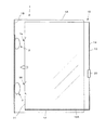
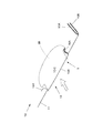
以下、この考案のファイルセットの具体的実施例を添付図面に基づいて説明する。図1〜図3はファイルセットの全体を示す図である。この考案のファイルセットは表裏のシート間に書類を挟み込み可能とした書類ファイル10と、複数の書類ファイルを綴じて収容可能としたバインダー1の組み合わせからなる。
Hereinafter, specific embodiments of the file set of the present invention will be described with reference to the accompanying drawings. 1 to 3 are diagrams showing the entire file set. The file set of the present invention is composed of a combination of a
書類ファイル10は可撓性と復元性を有する合成樹脂製の表側シートと裏側シートを重ね合わせ、少なくともシートの背側の端縁11とそれに隣り合う端縁の2辺を閉塞して、表裏のシート間に書類を挟み込み可能とした構成よりなるが、この実施例においては合成樹脂製のシートを2つ折りにして表側シート10Aと裏側シート10Bとして重ね合わせ、背折り部に隣り合う一方の端縁を溶着することにより、背側の端縁11とそれに隣り合う下側の端縁12の2辺を閉塞した構成としている。この考案の書類ファイル10はそれ単独で完結して使用することを前提としているものであり、ある程度の剛性が要求され、比較的厚手の可撓性と復元性を有する合成樹脂製のシートにより構成される。この場合、シートの素材としては塩化ビニル系樹脂やポリオレフィン系樹脂が想定されるが、これらに限られないことはもちろんである。また、シートはこの実施例においては透明なものを例示するが不透明なものであってもよいことは勿論である。
The
前記の書類ファイル10には、開放した前側の端縁13において表裏のシート10A、10B同士が開くことを防止するためにクリップが付属される(図20参照)。図18および19はその詳細を示す図であり、図中符号20はクリップを示す。このクリップは弾性を有する合成樹脂板を折り曲げて構成されるものであり、2つ折りした得られる表裏の支持板中の表側支持板20Bの先端をさらに手前内方に折り曲げることにより先端が裏側支持板20Aに向かって附勢して接する圧接板20Cとし、この圧接板20Cと裏側支持板20Aとの間に書類ファイル10の表裏のシート10A、10Bを挟み込む。この場合、書類ファイル10の表側のシート10Aの表面の端部には前記のクリップ20の離脱を防ぐための突起14が熱加工により突設される。なお、前記のクリップの構成はここに開示のものに限られず、また、書類ファイル10の前側の端縁13以外に上側の端縁にも付属させてもよいことはもちろんである。
A clip is attached to the
バインダー1は、背1Bの両側に表裏の表紙1A、1Aが開閉自在に連続する構成よりなり、背1Bの内側には書類ファイル10を係止により綴じるための複数個の薄板状の係止片15が擺動自在に突設される(図3参照)。
The
前記の係止片はこの実施例においては背1Bの上下2箇所に設けられるものであり、図5〜図15に下側の係止片3の詳細を図示する。この係止片3は剛性を有する合成樹脂により薄板状に構成されるものであり、幅狭の首部3Aの前方に先端に向かって収束する形状からなる幅広の顎部3Bを連続させることにより、顎部下縁を係止段部3C、3Dとした構成よりなる。この実施例においては、顎部3Bを平面ドーム状に構成し、顎部下縁の左右に係止段部3C、3Dを設けることにより全体として茸状の形状としている。
In this embodiment, the above-mentioned locking pieces are provided at two locations on the top and bottom of the
一方、書類ファイル10には前記の係止片に対応して係止穴が背側の端縁11の上下2箇所に設けられるものであり、図5〜図15に下側の係止穴16の詳細を図示する。この係止穴16は書類ファイル10の表裏いずれかのシート(ここでは表側のシート10A)に根元16A、16Aを残して切り抜かれる舌片状の切り抜きにして、開放した先端16Bを書類ファイルの背側の端縁11に接して配すると共に、残された根元16A、16Aを上記端縁より前側にオフセットして配した構成よりなる。そして、書類ファイル10の背側の端縁11に接して配される係止穴16の先端16Bの幅を、係止片3の首部3Aの幅より広く、且つ顎部3Bの幅より狭く設定すると共に、係止穴の根元16A、16Aの幅を係止片の顎部の幅より広く設定する。
On the other hand, the
前記の構成からなる係止片3および書類ファイル10の係止穴16の作用は次の通りである。
(1) 書類ファイル10を係止片3によりバインダー1に綴じるには、書類ファイルの背側の端縁11をバインダーの背1Bに向けて進行させ、裏側のシート10Bの表面と係止穴16の切り抜きにより生じる表側のシート10Aの舌片10Cの裏面の間から係止片の顎部3Bを進入させる(図1、5〜6、9、10〜11参照)。
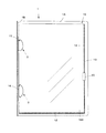
(2) この場合、係止片3の顎部3Bの幅は係止穴16の根元16A、16Aの幅より狭いので、さらに進行させることにより顎部は舌片10Cの裏面を越えて表側シート10Aの裏面と裏側のシート10Bの表面との間に挿通されることとなり、その段階で書類ファイル10を手前に引き戻せば、顎部3B下縁の係止段部3C、3Dが係止穴16の外側の書類ファイルの背側の端縁11の内方に係止することとなる(図2、7〜8、12〜15参照)。
The operation of the
(1) In order to bind the
(2) In this case, the width of the
図16はバインダー1の背1Bの上側の係止片2と、これに対応して書類ファイル10の背側の端縁11の下側に設けられる係止穴15の詳細を示す図である。これらの係止片および係止穴は前記した下側の係止片3および係止穴16と同じ構成にしてもよいが、この実施例では書類ファイルのバインダーからの取り外しを容易にするために次の構成としている。
FIG. 16 is a diagram showing details of the
すなわち、ここでは係止片2において幅狭の首部2Aの前方に先端に向かって収束する形状からなる幅広の顎部2Bを連続させることにより、顎部下縁に係止段部を設ける構成は下側の係止片3と共通するが、顎部を上方に偏位することにより係止段部2Cは上側のみに生じるようにしている。また、係止穴15は書類ファイル10の表裏いずれかのシート(ここでは表側のシート10A)に根元15A、15Aを残して切り抜かれる舌片10D状の切り抜きにして、開放した先端15Bを書類ファイルの背側の端縁11に接して配する構成は下側の係止片2と共通するが、残された根元15A、15Aは上側が上記端縁より前側にオフセットして配されるが、下側は端縁に接して配される。その結果、この係止片2は上側においてのみ係止し、下側は係止しないこととなる。
That is, here, the configuration in which the locking step portion is provided at the lower edge of the jaw portion by continuing the
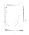
前記の構成よりなる上側の係止片2および係止穴15、下側の係止片3および係止穴16は、書類ファイル10のバインダー1からの取り外しが容易となる次の作用を生じる(図4、17参照)。
(1) 先ず、書類ファイル10を一旦上方にずらすことにより、下側の係止片3の下側の係止段部3Dの角と係止穴16の下側の角とが当接する。一方、この場合、下側の係止片3の上側の係止段部3Cと係止穴16の係止と、上側の係止片2の上側の係止段部2Cと係止穴15の係止は、それぞれの顎部の上側に対して係止穴の上側の角が離隔するので緩くなる。また、上側の係止片2と係止穴15はそもそも下側においては係止していない。
(2) そこで、下側の係止片3の下側の係止段部3Dの角と、係止穴16の下側角との当接箇所を支点として書類ファイルをてこ状に手前に回転させれば、上側の係止片2と係止穴15の下側は係止されていないことも相まって、係止が緩くなっている上下の係止片と係止穴の上側の係止は容易に解除される。
(3) この場合、図17に示すように下側の係止片3の顎部16Bは上半分以上が書類ファイル10から離脱しているので、今度は書類ファイルを下方にずらしながら手前に回転させれば、下側の係止片3の顎部16Bの下側の係止段部3Dと書類ファイルの背側の端縁11の係止は容易に解除され、書類ファイルをバインダー1から取り外すことが可能となる。
The
(1) First, the
(2) Therefore, the document file is rotated to the front with the contact point between the lower corner of the
(3) In this case, as shown in FIG. 17, since the upper half of the
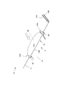
図20は係止穴の異なる実施例を示す図である。この実施例においては係止穴36を舌片を残さずに、穴状の切り欠きとしているものであり、先端36Bを書類ファイル10の背側の端縁11に接して配すると共に、後端36Aを上記端縁より前側にオフセットして配している。
FIG. 20 is a view showing different embodiments of the locking holes. In this embodiment, the locking
1 バインダー
2 上側の係止片
2A (上側の係止片の)首部
2B (上側の係止片の)顎部
3 下側の係止片
3A (下側の係止片の)首部
3B (下側の係止片の)顎部
10 書類ファイル
11 (書類ファイルの)背側の端縁
15 上側の係止穴
16 下側の係止穴
20 クリップ
DESCRIPTION OF
Claims (5)
Priority Applications (1)
| Application Number | Priority Date | Filing Date | Title |
|---|---|---|---|
| JP2008006804U JP3147002U (en) | 2008-09-29 | 2008-09-29 | File set |
Applications Claiming Priority (1)
| Application Number | Priority Date | Filing Date | Title |
|---|---|---|---|
| JP2008006804U JP3147002U (en) | 2008-09-29 | 2008-09-29 | File set |
Publications (1)
| Publication Number | Publication Date |
|---|---|
| JP3147002U true JP3147002U (en) | 2008-12-11 |
Family
ID=43296680
Family Applications (1)
| Application Number | Title | Priority Date | Filing Date |
|---|---|---|---|
| JP2008006804U Expired - Fee Related JP3147002U (en) | 2008-09-29 | 2008-09-29 | File set |
Country Status (1)
| Country | Link |
|---|---|
| JP (1) | JP3147002U (en) |
Cited By (1)
| Publication number | Priority date | Publication date | Assignee | Title |
|---|---|---|---|---|
| JP6488441B1 (en) * | 2018-08-15 | 2019-03-20 | 寛之 栗飯原 | Paper piece container |
-
2008
- 2008-09-29 JP JP2008006804U patent/JP3147002U/en not_active Expired - Fee Related
Cited By (1)
| Publication number | Priority date | Publication date | Assignee | Title |
|---|---|---|---|---|
| JP6488441B1 (en) * | 2018-08-15 | 2019-03-20 | 寛之 栗飯原 | Paper piece container |
Similar Documents
| Publication | Publication Date | Title |
|---|---|---|
| JP2013166249A (en) | Paper sheet holder | |
| JP3147002U (en) | File set | |
| JP2008012785A (en) | File | |
| JP4548786B2 (en) | Attachment for double clip | |
| KR200388307Y1 (en) | Vinyl file for a document | |
| JP3164506U (en) | Clear folder | |
| JP6539001B1 (en) | Paper storage | |
| JP2001287489A (en) | Filing implement | |
| JP2008087455A (en) | Storage device | |
| JP6488441B1 (en) | Paper piece container | |
| JP2010201725A (en) | File | |
| JP4272949B2 (en) | Sheet-like material holder | |
| JP3609899B2 (en) | Case file | |
| JP3092325U (en) | Clear holder | |
| JP3156449U (en) | Clear folder | |
| JP4809807B2 (en) | Key storage binder | |
| JPH1058876A (en) | Holder | |
| JP2021045925A (en) | Document file | |
| JP3729334B2 (en) | Document holder | |
| JP3055818U (en) | Document holder with removable binder | |
| JPH08310175A (en) | File | |
| TWI238122B (en) | Ring-buckle close-open device for file holder (box) | |
| JP3152187U (en) | Paper binding tool | |
| JP2002079787A (en) | Document arranging box | |
| JP2001232981A (en) | Holder for document and the like |
Legal Events
| Date | Code | Title | Description |
|---|---|---|---|
| R150 | Certificate of patent or registration of utility model |
Free format text: JAPANESE INTERMEDIATE CODE: R150 |
|
| FPAY | Renewal fee payment (event date is renewal date of database) |
Free format text: PAYMENT UNTIL: 20111119 Year of fee payment: 3 |
|
| FPAY | Renewal fee payment (event date is renewal date of database) |
Free format text: PAYMENT UNTIL: 20121119 Year of fee payment: 4 |
|
| FPAY | Renewal fee payment (event date is renewal date of database) |
Free format text: PAYMENT UNTIL: 20131119 Year of fee payment: 5 |
|
| LAPS | Cancellation because of no payment of annual fees |