EP1622115A2 - Plasmaanzeigegerät mit dessen Steuerungsmethode - Google Patents
Plasmaanzeigegerät mit dessen Steuerungsmethode Download PDFInfo
- Publication number
- EP1622115A2 EP1622115A2 EP05016180A EP05016180A EP1622115A2 EP 1622115 A2 EP1622115 A2 EP 1622115A2 EP 05016180 A EP05016180 A EP 05016180A EP 05016180 A EP05016180 A EP 05016180A EP 1622115 A2 EP1622115 A2 EP 1622115A2
- Authority
- EP
- European Patent Office
- Prior art keywords
- pulse
- sustain
- peak
- peak pulse
- plasma display
- Prior art date
- Legal status (The legal status is an assumption and is not a legal conclusion. Google has not performed a legal analysis and makes no representation as to the accuracy of the status listed.)
- Withdrawn
Links
Images



Classifications
-
- G—PHYSICS
- G09—EDUCATION; CRYPTOGRAPHY; DISPLAY; ADVERTISING; SEALS
- G09G—ARRANGEMENTS OR CIRCUITS FOR CONTROL OF INDICATING DEVICES USING STATIC MEANS TO PRESENT VARIABLE INFORMATION
- G09G3/00—Control arrangements or circuits, of interest only in connection with visual indicators other than cathode-ray tubes
- G09G3/20—Control arrangements or circuits, of interest only in connection with visual indicators other than cathode-ray tubes for presentation of an assembly of a number of characters, e.g. a page, by composing the assembly by combination of individual elements arranged in a matrix no fixed position being assigned to or needed to be assigned to the individual characters or partial characters
- G09G3/22—Control arrangements or circuits, of interest only in connection with visual indicators other than cathode-ray tubes for presentation of an assembly of a number of characters, e.g. a page, by composing the assembly by combination of individual elements arranged in a matrix no fixed position being assigned to or needed to be assigned to the individual characters or partial characters using controlled light sources
- G09G3/28—Control arrangements or circuits, of interest only in connection with visual indicators other than cathode-ray tubes for presentation of an assembly of a number of characters, e.g. a page, by composing the assembly by combination of individual elements arranged in a matrix no fixed position being assigned to or needed to be assigned to the individual characters or partial characters using controlled light sources using luminous gas-discharge panels, e.g. plasma panels
- G09G3/288—Control arrangements or circuits, of interest only in connection with visual indicators other than cathode-ray tubes for presentation of an assembly of a number of characters, e.g. a page, by composing the assembly by combination of individual elements arranged in a matrix no fixed position being assigned to or needed to be assigned to the individual characters or partial characters using controlled light sources using luminous gas-discharge panels, e.g. plasma panels using AC panels
- G09G3/296—Driving circuits for producing the waveforms applied to the driving electrodes
-
- G—PHYSICS
- G09—EDUCATION; CRYPTOGRAPHY; DISPLAY; ADVERTISING; SEALS
- G09G—ARRANGEMENTS OR CIRCUITS FOR CONTROL OF INDICATING DEVICES USING STATIC MEANS TO PRESENT VARIABLE INFORMATION
- G09G3/00—Control arrangements or circuits, of interest only in connection with visual indicators other than cathode-ray tubes
- G09G3/20—Control arrangements or circuits, of interest only in connection with visual indicators other than cathode-ray tubes for presentation of an assembly of a number of characters, e.g. a page, by composing the assembly by combination of individual elements arranged in a matrix no fixed position being assigned to or needed to be assigned to the individual characters or partial characters
- G09G3/22—Control arrangements or circuits, of interest only in connection with visual indicators other than cathode-ray tubes for presentation of an assembly of a number of characters, e.g. a page, by composing the assembly by combination of individual elements arranged in a matrix no fixed position being assigned to or needed to be assigned to the individual characters or partial characters using controlled light sources
- G09G3/28—Control arrangements or circuits, of interest only in connection with visual indicators other than cathode-ray tubes for presentation of an assembly of a number of characters, e.g. a page, by composing the assembly by combination of individual elements arranged in a matrix no fixed position being assigned to or needed to be assigned to the individual characters or partial characters using controlled light sources using luminous gas-discharge panels, e.g. plasma panels
- G09G3/288—Control arrangements or circuits, of interest only in connection with visual indicators other than cathode-ray tubes for presentation of an assembly of a number of characters, e.g. a page, by composing the assembly by combination of individual elements arranged in a matrix no fixed position being assigned to or needed to be assigned to the individual characters or partial characters using controlled light sources using luminous gas-discharge panels, e.g. plasma panels using AC panels
- G09G3/291—Control arrangements or circuits, of interest only in connection with visual indicators other than cathode-ray tubes for presentation of an assembly of a number of characters, e.g. a page, by composing the assembly by combination of individual elements arranged in a matrix no fixed position being assigned to or needed to be assigned to the individual characters or partial characters using controlled light sources using luminous gas-discharge panels, e.g. plasma panels using AC panels controlling the gas discharge to control a cell condition, e.g. by means of specific pulse shapes
- G09G3/294—Control arrangements or circuits, of interest only in connection with visual indicators other than cathode-ray tubes for presentation of an assembly of a number of characters, e.g. a page, by composing the assembly by combination of individual elements arranged in a matrix no fixed position being assigned to or needed to be assigned to the individual characters or partial characters using controlled light sources using luminous gas-discharge panels, e.g. plasma panels using AC panels controlling the gas discharge to control a cell condition, e.g. by means of specific pulse shapes for lighting or sustain discharge
- G09G3/2942—Control arrangements or circuits, of interest only in connection with visual indicators other than cathode-ray tubes for presentation of an assembly of a number of characters, e.g. a page, by composing the assembly by combination of individual elements arranged in a matrix no fixed position being assigned to or needed to be assigned to the individual characters or partial characters using controlled light sources using luminous gas-discharge panels, e.g. plasma panels using AC panels controlling the gas discharge to control a cell condition, e.g. by means of specific pulse shapes for lighting or sustain discharge with special waveforms to increase luminous efficiency
-
- G—PHYSICS
- G09—EDUCATION; CRYPTOGRAPHY; DISPLAY; ADVERTISING; SEALS
- G09G—ARRANGEMENTS OR CIRCUITS FOR CONTROL OF INDICATING DEVICES USING STATIC MEANS TO PRESENT VARIABLE INFORMATION
- G09G3/00—Control arrangements or circuits, of interest only in connection with visual indicators other than cathode-ray tubes
- G09G3/20—Control arrangements or circuits, of interest only in connection with visual indicators other than cathode-ray tubes for presentation of an assembly of a number of characters, e.g. a page, by composing the assembly by combination of individual elements arranged in a matrix no fixed position being assigned to or needed to be assigned to the individual characters or partial characters
- G09G3/22—Control arrangements or circuits, of interest only in connection with visual indicators other than cathode-ray tubes for presentation of an assembly of a number of characters, e.g. a page, by composing the assembly by combination of individual elements arranged in a matrix no fixed position being assigned to or needed to be assigned to the individual characters or partial characters using controlled light sources
- G09G3/28—Control arrangements or circuits, of interest only in connection with visual indicators other than cathode-ray tubes for presentation of an assembly of a number of characters, e.g. a page, by composing the assembly by combination of individual elements arranged in a matrix no fixed position being assigned to or needed to be assigned to the individual characters or partial characters using controlled light sources using luminous gas-discharge panels, e.g. plasma panels
- G09G3/288—Control arrangements or circuits, of interest only in connection with visual indicators other than cathode-ray tubes for presentation of an assembly of a number of characters, e.g. a page, by composing the assembly by combination of individual elements arranged in a matrix no fixed position being assigned to or needed to be assigned to the individual characters or partial characters using controlled light sources using luminous gas-discharge panels, e.g. plasma panels using AC panels
-
- G—PHYSICS
- G09—EDUCATION; CRYPTOGRAPHY; DISPLAY; ADVERTISING; SEALS
- G09G—ARRANGEMENTS OR CIRCUITS FOR CONTROL OF INDICATING DEVICES USING STATIC MEANS TO PRESENT VARIABLE INFORMATION
- G09G3/00—Control arrangements or circuits, of interest only in connection with visual indicators other than cathode-ray tubes
- G09G3/20—Control arrangements or circuits, of interest only in connection with visual indicators other than cathode-ray tubes for presentation of an assembly of a number of characters, e.g. a page, by composing the assembly by combination of individual elements arranged in a matrix no fixed position being assigned to or needed to be assigned to the individual characters or partial characters
- G09G3/22—Control arrangements or circuits, of interest only in connection with visual indicators other than cathode-ray tubes for presentation of an assembly of a number of characters, e.g. a page, by composing the assembly by combination of individual elements arranged in a matrix no fixed position being assigned to or needed to be assigned to the individual characters or partial characters using controlled light sources
- G09G3/28—Control arrangements or circuits, of interest only in connection with visual indicators other than cathode-ray tubes for presentation of an assembly of a number of characters, e.g. a page, by composing the assembly by combination of individual elements arranged in a matrix no fixed position being assigned to or needed to be assigned to the individual characters or partial characters using controlled light sources using luminous gas-discharge panels, e.g. plasma panels
- G09G3/288—Control arrangements or circuits, of interest only in connection with visual indicators other than cathode-ray tubes for presentation of an assembly of a number of characters, e.g. a page, by composing the assembly by combination of individual elements arranged in a matrix no fixed position being assigned to or needed to be assigned to the individual characters or partial characters using controlled light sources using luminous gas-discharge panels, e.g. plasma panels using AC panels
- G09G3/291—Control arrangements or circuits, of interest only in connection with visual indicators other than cathode-ray tubes for presentation of an assembly of a number of characters, e.g. a page, by composing the assembly by combination of individual elements arranged in a matrix no fixed position being assigned to or needed to be assigned to the individual characters or partial characters using controlled light sources using luminous gas-discharge panels, e.g. plasma panels using AC panels controlling the gas discharge to control a cell condition, e.g. by means of specific pulse shapes
- G09G3/294—Control arrangements or circuits, of interest only in connection with visual indicators other than cathode-ray tubes for presentation of an assembly of a number of characters, e.g. a page, by composing the assembly by combination of individual elements arranged in a matrix no fixed position being assigned to or needed to be assigned to the individual characters or partial characters using controlled light sources using luminous gas-discharge panels, e.g. plasma panels using AC panels controlling the gas discharge to control a cell condition, e.g. by means of specific pulse shapes for lighting or sustain discharge
- G09G3/2948—Control arrangements or circuits, of interest only in connection with visual indicators other than cathode-ray tubes for presentation of an assembly of a number of characters, e.g. a page, by composing the assembly by combination of individual elements arranged in a matrix no fixed position being assigned to or needed to be assigned to the individual characters or partial characters using controlled light sources using luminous gas-discharge panels, e.g. plasma panels using AC panels controlling the gas discharge to control a cell condition, e.g. by means of specific pulse shapes for lighting or sustain discharge by increasing the total sustaining time with respect to other times in the frame
-
- G—PHYSICS
- G09—EDUCATION; CRYPTOGRAPHY; DISPLAY; ADVERTISING; SEALS
- G09G—ARRANGEMENTS OR CIRCUITS FOR CONTROL OF INDICATING DEVICES USING STATIC MEANS TO PRESENT VARIABLE INFORMATION
- G09G3/00—Control arrangements or circuits, of interest only in connection with visual indicators other than cathode-ray tubes
- G09G3/20—Control arrangements or circuits, of interest only in connection with visual indicators other than cathode-ray tubes for presentation of an assembly of a number of characters, e.g. a page, by composing the assembly by combination of individual elements arranged in a matrix no fixed position being assigned to or needed to be assigned to the individual characters or partial characters
- G09G3/22—Control arrangements or circuits, of interest only in connection with visual indicators other than cathode-ray tubes for presentation of an assembly of a number of characters, e.g. a page, by composing the assembly by combination of individual elements arranged in a matrix no fixed position being assigned to or needed to be assigned to the individual characters or partial characters using controlled light sources
- G09G3/28—Control arrangements or circuits, of interest only in connection with visual indicators other than cathode-ray tubes for presentation of an assembly of a number of characters, e.g. a page, by composing the assembly by combination of individual elements arranged in a matrix no fixed position being assigned to or needed to be assigned to the individual characters or partial characters using controlled light sources using luminous gas-discharge panels, e.g. plasma panels
- G09G3/288—Control arrangements or circuits, of interest only in connection with visual indicators other than cathode-ray tubes for presentation of an assembly of a number of characters, e.g. a page, by composing the assembly by combination of individual elements arranged in a matrix no fixed position being assigned to or needed to be assigned to the individual characters or partial characters using controlled light sources using luminous gas-discharge panels, e.g. plasma panels using AC panels
- G09G3/296—Driving circuits for producing the waveforms applied to the driving electrodes
- G09G3/2965—Driving circuits for producing the waveforms applied to the driving electrodes using inductors for energy recovery
-
- G—PHYSICS
- G09—EDUCATION; CRYPTOGRAPHY; DISPLAY; ADVERTISING; SEALS
- G09G—ARRANGEMENTS OR CIRCUITS FOR CONTROL OF INDICATING DEVICES USING STATIC MEANS TO PRESENT VARIABLE INFORMATION
- G09G2310/00—Command of the display device
- G09G2310/02—Addressing, scanning or driving the display screen or processing steps related thereto
- G09G2310/0264—Details of driving circuits
- G09G2310/0267—Details of drivers for scan electrodes, other than drivers for liquid crystal, plasma or OLED displays
-
- G—PHYSICS
- G09—EDUCATION; CRYPTOGRAPHY; DISPLAY; ADVERTISING; SEALS
- G09G—ARRANGEMENTS OR CIRCUITS FOR CONTROL OF INDICATING DEVICES USING STATIC MEANS TO PRESENT VARIABLE INFORMATION
- G09G2310/00—Command of the display device
- G09G2310/06—Details of flat display driving waveforms
-
- G—PHYSICS
- G09—EDUCATION; CRYPTOGRAPHY; DISPLAY; ADVERTISING; SEALS
- G09G—ARRANGEMENTS OR CIRCUITS FOR CONTROL OF INDICATING DEVICES USING STATIC MEANS TO PRESENT VARIABLE INFORMATION
- G09G2320/00—Control of display operating conditions
- G09G2320/02—Improving the quality of display appearance
-
- G—PHYSICS
- G09—EDUCATION; CRYPTOGRAPHY; DISPLAY; ADVERTISING; SEALS
- G09G—ARRANGEMENTS OR CIRCUITS FOR CONTROL OF INDICATING DEVICES USING STATIC MEANS TO PRESENT VARIABLE INFORMATION
- G09G2330/00—Aspects of power supply; Aspects of display protection and defect management
- G09G2330/02—Details of power systems and of start or stop of display operation
- G09G2330/021—Power management, e.g. power saving
- G09G2330/023—Power management, e.g. power saving using energy recovery or conservation
- G09G2330/024—Power management, e.g. power saving using energy recovery or conservation with inductors, other than in the electrode driving circuitry of plasma displays
Definitions
- the present invention relates to an apparatus and method for driving a plasma display panel, and more particularly, to an apparatus and method for driving a plasma display panel using a peak pulse.
- FIG. 1 shows driving waveforms for use in a conventional plasma display panel.
- the conventional plasma display panel is driven according to a reset period (that is, initialization period) for initializing the entire screen, an address period for selecting cells, and a sustain period for maintaining the discharge of the selected cells.
- a reset period that is, initialization period
- a rising ramp pulse Ramp-up is applied simultaneously to all scan electrodes Y.
- a dark discharge that is, a set-up discharge
- positive wall charges are accumulated on address electrodes X and sustain electrodes Z and negative wall charges are accumulated on the scan electrodes Y.
- a falling ramp pulse Ramp-down is applied.
- the falling ramp pulse Ramp-down falls from a positive voltage lower than the peak voltage of the rising ramp pulse Ramp-up to a ground voltage GND or a specific negative voltage, thus partially erasing wall charges excessively formed in the cells.
- the amount of wall charges which is sufficient to stably cause an address discharge remain uniform in the cells.
- a scan pulse Scan is applied sequentially to the scan electrodes Y and the sustain electrodes Z, and simultaneously data pulse data is applied to the address electrodes X in synchronization with the scan pulse Scan.
- a voltage difference between the scan pulse Scan and the data pulse data is added with a wall voltage created during the initialization period, thereby causing an address discharge in cells to which the data pulse data is applied.
- the amount of wall charges which is sufficient to cause a discharge when a sustain voltage is applied is formed.
- a bias voltage Z dc is applied to the sustain electrodes Z during the set-down period SD and the address period so as to reduce a voltage difference between the sustain electrodes Z and the scan electrodes Y and thus prevent a wrong discharge from occurring between the sustain electrodes Z and the scan electrodes Y.
- a sustain pulse Sus is applied alternately to the scan electrodes Y and the sustain electrodes Z.
- a wall voltage in the cells is added with the sustain pulse Sus and accordingly a sustain discharge, that is, a display discharge occurs between the scan electrodes Y and the sustain electrodes Z whenever the sustain pulse Sus is applied.
- a ramp waveform Ramp-ers having a narrow pulse width and a low voltage is supplied to the sustain electrodes Z, thereby erasing wall charges which remain in the cells of the entire screen.
- an object of the present invention is to solve at least the problems and disadvantages of the background art.
- the present invention provides a plasma display apparatus which is capable of enhancing the brightness of a plasma display panel without increasing the number of sustain pulses.
- the present invention also provides a plasma display apparatus which is capable of minimizing power consumption and the amount of heat generation.
- a plasma display apparatus including: a plasma display panel including a scan electrode and a sustain electrode; a scan electrode driver applying a first sustain pulse to the scan electrode; a sustain electrode driver applying a second sustain pulse to the sustain electrode alternately with the first sustain pulse; and a peak pulse applying unit causing a peak pulse to overlap the first sustain pulse and the second sustain pulse when the first sustain pulse and the second sustain pulse are alternately applied to the scan electrode and the sustain electrode.
- a plasma display apparatus including: a plasma display panel including a scan electrode and a sustain electrode; a scan electrode driver applying a first sustain pulse to the scan electrode; a sustain electrode driver applying a second sustain pulse to the sustain electrode alternately with the first sustain pulse; and a peak pulse generator causing a peak pulse to overlap sustain pulses when the sustain pulses are respectively applied to the scan electrode and the sustain electrode, wherein the peak pulse generator includes: a first peak pulse generator outputting a peak pulse to overlap a sustain pulse applied to the scan electrode; a first coupling circuit unit causing the peak pulse output from the first peak pulse generator to overlap the sustain pulse applied to the scan electrode; a second peak pulse generator outputting a peak pulse to overlap a sustain pulse applied to the sustain electrode; and a second coupling circuit unit causing the peak pulse output from the second peak pulse generator to overlap the sustain pulse applied to the sustain electrode.
- a driving method of a plasma display apparatus including: causing a first peak pulse to overlap a first sustain pulse when the first sustain pulse is applied to a scan electrode; and causing a second peak pulse to overlap a second sustain pulse when the second sustain pulse is applied to a sustain electrode.
- a plasma display apparatus and a driving method thereof, according to the present invention have advantages of enhancing brightness and contrast, minimizing power consumption and the amount of heat generation, and ensuring the reliability and stable operation of the plasma display apparatus, by causing a peak pulse to overlap a sustain pulse without increasing the number of sustain pulses.
- a plasma display apparatus including: a plasma display panel including a scan electrode and a sustain electrode; a scan electrode driver applying a first sustain pulse to the scan electrode; a sustain electrode driver applying a second sustain pulse to the sustain electrode alternately with the first sustain pulse; and a peak pulse applying unit causing a peak pulse to overlap the first sustain pulse and the second sustain pulse when the first sustain pulse and the second sustain pulse are alternately applied to the scan electrode and the sustain electrode.
- the peak pulse applying unit causes the peak pulse to overlap the first sustain pulse and the second sustain pulse when sustain voltages respectively forming the first sustain pulse and the second sustain pulse are respectively applied to the scan electrode and the sustain electrode.
- the peak pulse applying unit converts an input rectangular wave into the peak pulse, the peak pulse having a trigger pulse waveform, and causes the peak pulse to overlap the first sustain pulse and the second sustain pulse.
- the scan electrode driver includes a first energy recovery circuit and the peak pulse applying unit causes the peak pulse to overlap the first sustain pulse when a sustain voltage forming the first sustain pulse is applied after energy is supplied by the first energy recovery circuit.
- the sustain electrode driver includes a second energy recovery circuit, and the peak pulse applying unit causes the peak pulse to overlap the second sustain pulse when a sustain voltage constituting the second sustain pulse is applied after energy is supplied by the second energy recovery circuit.
- the peak pulse applying unit includes: a first peak pulse generator outputting a peak pulse to overlap the first sustain pulse; a first coupling circuit unit causing the peak pulse output from the first peak pulse generator to overlap the first sustain pulse; a second peak pulse generator outputting a peak pulse to overlap the second sustain pulse; and a second coupling circuit unit causing the peak pulse output from the second peak pulse generator to overlap the second sustain pulse.
- the first peak pulse generator includes a differential circuit and converts a rectangular waveform received through the differential circuit into a positive peak pulse and a negative peak pulse, each having trigger pulse waveforms, and the first coupling circuit unit causes the positive peak pulse to overlap the first sustain pulse.
- the second peak pulse generator includes a differential circuit and converts a rectangular waveform received through the differential circuit into a positive peak pulse and a negative peak pulse, each having trigger pulse waveforms, and the second coupling circuit unit causes the positive peak pulse to overlap the second sustain pulse.
- the first peak pulse generator generates the positive peak pulse of the trigger pulse waveform when the rectangular waveform rises and generates the negative peak pulse when the rectangular waveform falls.
- the second peak pulse generator generates the positive peak pulse of the trigger pulse waveform when the rectangular waveform rises and generates the negative peak pulse when the rectangular waveform falls.
- the first coupling circuit unit includes a first diode having an anode terminal connected to the first peak pulse generator, and a first capacitor having one end connected to a cathode terminal of the first diode and the other end connected to the scan electrode.
- the second coupling circuit unit includes a second diode having an anode terminal connected to the second peak pulse generator, and a second capacitor having one end connected to a cathode terminal of the second diode and the other end connected to the sustain electrode.
- the scan electrode driver includes a first energy recovery circuit, and the peak pulse applying unit causes the peak pulse to overlap the first sustain pulse when a sustain voltage constituting the first sustain pulse is applied after energy is supplied by the first energy recovery circuit.
- the sustain electrode driver includes a second energy recovery circuit, and the peak pulse applying unit causes the peak pulse to overlap the second sustain pulse when a sustain voltage constituting the second sustain pulse is applied after energy is supplied by the second energy recovery circuit.
- a plasma display apparatus including: a plasma display panel including a scan electrode and a sustain electrode; a scan electrode driver applying a first sustain pulse to the scan electrode; a sustain electrode driver applying a second sustain pulse to the sustain electrode alternately with the first sustain pulse; and a peak pulse generator causing a peak pulse to overlap sustain pulses when the sustain pulses are respectively applied to the scan electrode and the sustain electrode, wherein the peak pulse generator includes: a first peak pulse generator outputting a peak pulse to overlap a sustain pulse applied to the scan electrode; a first coupling circuit unit causing the peak pulse output from the first peak pulse generator to overlap the sustain pulse applied to the scan electrode; a second peak pulse generator outputting a peak pulse to overlap a sustain pulse applied to the sustain electrode; and a second coupling circuit unit causing the peak pulse output from the second peak pulse generator to overlap the sustain pulse applied to the sustain electrode.
- a driving method of a plasma display apparatus including: causing a first peak pulse to overlap a first sustain pulse when the first sustain pulse is applied to a scan electrode; and causing a second peak pulse to overlap a second sustain pulse when the second sustain pulse is applied to the sustain electrode.
- the first peak pulse overlaps the first sustain pulse when a sustain voltage constituting the first sustain pulse is applied to the scan electrode.
- the second peak pulse overlaps the second sustain pulse when a sustain voltage constituting the second sustain pulse is applied to the sustain electrode.
- the first peak pulse overlaps the first sustain pulse when a sustain voltage is applied after energy for forming the first sustain pulse is supplied to a plasma display panel.
- the second peak pulse overlaps the second sustain pulse when a sustain voltage is applied after energy for forming the second sustain pulse is supplied to a plasma display panel.
- FIG. 1 shows driving waveforms for used in a conventional plasma display panel.
- FIG. 2 is a block diagram of a plasma display apparatus according to the present invention.
- FIG. 3 shows a circuit configuration composed of a first peak pulse generator, a second peak pulse generator, a first coupling circuit unit, a second coupling circuit unit, and electrode drivers, which is included in the plasma display apparatus according to the present invention, according to a first embodiment of the present invention.
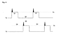
- FIG. 4 is a first embodiment of a sustain pulse waveform according to the present invention.
- FIG. 5 shows a circuit configuration composed of a first peak pulse generator, a second peak pulse generator, a first coupling circuit unit, a second coupling circuit unit, and electrode drivers, which is included in the plasma display apparatus according to the present invention, according to a second embodiment of the present invention.
- FIG. 6 is a second embodiment of a sustain pulse waveform according to the present invention.
- FIG. 2 is a block diagram of a plasma display apparatus according to the present invention.
- the plasma display apparatus according to the present invention includes a controller unit 210, an address electrode driver 220, a scan electrode driver 230, a sustain electrode driver 240, a sustain pulse controller 250, and a peak pulse applying unit 255.
- controller unit >
- the controller unit 210 controls the number of subfields corresponding to image data and the number of sustain pulses assigned to each subfield, outputs a Y timing signal and a Z timing signal for applying corresponding sustain pulses to each subfield, and outputs a first peak pulse-forming signal and a second peak pulse-forming signal respectively in synchronization with the Y timing signal and the Z timing signal.
- the address electrode driver 220 applies a data pulse to address electrodes according to an X timing signal.
- the scan electrode driver 230 applies a sustain pulse to scan electrodes according to the Y timing signal.
- the sustain electrode driver 240 applies a sustain pulse to sustain electrodes according to the Z timing signal.
- the sustain pulse controller 250 controls the scan electrode driver 230 and the sustain electrode driver 240, according to the number of sustain pulses assigned to each subfield by the controller unit 210, the Y timing signal, and the Z timing signal.
- the peak pulse applying unit 255 generates a peak pulse and causes the peak pulse to overlap a sustain pulse when the sustain pulse is applied alternately to the scan electrodes and the sustain electrodes.
- the peak pulse applying unit 255 includes a first peak pulse generator 260, a first coupling circuit unit 270, a second peak pulse generator 280, and a second coupling circuit unit 290.
- the first peak pulse generator 260 receives the first peak pulse-forming signal from the controller unit 210 and outputs a peak pulse.
- the first peak pulse generator 260 includes a differential circuit, and receives a first peak pulse-forming signal with a rectangular waveform and outputs a trigger pulse through the differential circuit. That is, the first peak pulse generator 260 outputs a positive peak pulse with a trigger pulse waveform when the rectangular waveform rises, and outputs a negative peak pulse with a trigger pulse waveform when the rectangular waveform falls.
- the first coupling circuit unit 270 removes the negative peak pulse output from the first peak pulse generator 260 and causes the positive peak pulse to overlap the sustain pulse which is applied to the scan electrodes.
- the first coupling circuit unit 270 causes the positive peak pulse to overlap the sustain pulse when the corresponding sustain voltage is applied to the scan electrodes.
- the second peak pulse generator 280 receives the second peak pulse-forming signal from the controller unit 210 and outputs a peak pulse.
- the second peak pulse generator 280 includes a differential circuit, and receives a second peak pulse-forming signal with a rectangular waveform and outputs a trigger pulse through the differential circuit. That is, the second peak pulse generator 280 outputs a positive peak pulse with a trigger pulse waveform when the rectangular waveform rises, and outputs a negative peak pulse with a trigger pulse waveform when the rectangular waveform falls.
- the second coupling circuit unit 290 removes the negative peak pulse output from the second peak pulse generator 280 and causes the positive peak pulse to overlap the sustain pulse which is applied to the sustain electrodes.
- the second coupling circuit unit 290 causes the positive peak pulse to overlap the sustain pulse when the corresponding sustain voltage is applied to the sustain electrodes.
- FIG. 3 shows a circuit configuration composed of a first peak pulse generator, a second peak pulse generator, a first coupling circuit unit, a second coupling circuit unit, and electrode drivers, which is included in the plasma display apparatus according to the present invention, according to a first embodiment of the present invention.
- FIG. 4 is a first embodiment of a sustain pulse waveform according to the present invention.
- a first peak pulse generator 260 which receives a first peak pulse-forming signal with a rectangular waveform from a controller unit 210, outputs a positive peak pulse with a trigger pulse waveform and a negative peak pulse with a trigger pulse waveform.
- the first coupling circuit unit 270 includes a first diode D1 and a first capacitor C 1.
- the anode terminal of the first diode D1 is connected to the first peak pulse generator 260 and the cathode terminal of the first diode D1 is connected to one end of the first capacitor C1. Also, the other end of the first capacitor C1 is connected to a scan electrode Y.
- the positive peak pulse output from the first peak pulse generator 260 is applied to the scan electrode Y via the first diode D1 and the first capacitor C1 of the first coupling circuit unit 270. Also, the negative peak pulse output from the first peak pulse generator 260 is blocked by the first diode D1 of the first coupling unit 270.
- the peak pulse formed through the first coupling circuit unit 270 overlaps a sustain voltage V s which is applied to a panel capacitor C p when a first switch Q1 of the scan electrode driver 230 is turned on.
- the first peak pulse generator 260 outputs the positive peak pulse when the scan electrode driver 230 applies the sustain voltage V s to the scan electrode Y. Accordingly, as shown in FIG. 4, since the positive peak pulse formed through the first coupling circuit unit 270 overlaps the sustain voltage V s when the sustain voltage V s is applied to the scan electrode Y, the voltage V y of the scan electrode Y appears as the overlapped waveform of the sustain pulse V s and the peak pulse.
- the first peak pulse generator 260 applies the positive peak pulse to the scan electrode Y through the first coupling circuit unit 270. Accordingly, the voltage V y of the scan electrode Y appears as the overlapped waveform of the sustain pulse V s and the peak pulse.
- the second peak pulse generator 280 and the second coupling circuit unit 290 operate in the similar manner to the first peak pulse generator 260 and the first coupling circuit unit 270.
- the second coupling circuit unit 290 includes a second diode D2 and a second capacitor C2.
- a positive peak pulse output from the second peak pulse generator 280 is applied to a sustain electrode Z via the second coupling circuit unit 290.
- a negative peak pulse output from the second peak pulse generator 280 is blocked by the second diode D2 of the second coupling circuit unit 290.
- a peak pulse formed through the second coupling circuit unit 290 overlaps a sustain voltage V s which is applied to the sustain electrode Z when a third switch Q3 of the sustain electrode driver 240 is turned on.
- the second peak pulse generator 280 outputs the positive peak pulse when the sustain electrode driver 240 applies the sustain pulse V s to the sustain electrode Z. Accordingly, as shown in FIG. 4, since the positive peak pulse formed through the second coupling circuit unit 290 overlaps the sustain voltage V s when the sustain voltage V s is applied to the sustain electrode Z, the voltage V z of the sustain electrode Z appears as the overlapped waveform of the sustain pulse V s and the peak pulse.
- the second peak pulse generator 280 applies the positive peak pulse to the sustain electrode Z through the second coupling circuit unit 290. Accordingly, the voltage V z of the sustain electrode Z appears as the overlapped waveform of the sustain pulse V s and the peak pulse.
- each of the voltages V y and V z of the scan electrode Y and the sustain electrode Z appears as the overlapped waveform of the sustain pulse V s of a square wave and the peak pulse.
- FIG. 5 shows a circuit configuration composed of a first peak pulse generator, a second peak pulse generator, a first coupling circuit unit, a second coupling circuit unit, and electrode drivers, which is included in the plasma display apparatus according to the present invention, according to a second embodiment of the present invention.
- FIG. 6 is a second embodiment of a sustain pulse waveform according to the present invention.
- the scan electrode driver 230 and the sustain electrode driver 240 include no energy recovery circuit, while in the second embodiment shown in FIG. 5, the scan electrode driver 230 and the sustain electrode driver 240 respectively include a first energy recovery circuit 235 and a second energy recovery circuit 245.
- the first peak pulse generator 260, the first coupling circuit unit 270, the second peak pulse generator 280, and the second coupling circuit unit 290 apply a peak pulse to a scan electrode Y or a sustain electrode Z when a sustain voltage V s is applied after energy is supplied from a first energy supply/recovery capacitor C er1 or a second energy supply/recovery capacitor C er2 .
- each of the voltages V y and V z of the scan electrode Y or the sustain electrode Z appears as the overlapped waveform of the sustain pulse V s and the peak pulse.
- a strong discharge is once generated by applying a peak pulse and another discharge is generated by applying a sustain pulse. That is, since a strong discharge is generated by a peak pulse while a discharge is discharged by a sustain pulse, brightness and contrast increase.
- the plasma display apparatus has advantages of enhancing brightness and contrast, minimizing power consumption and the amount of heat generation, and ensuring the reliability and stable operation of the plasma display apparatus, without increasing the number of sustain pulses.
Landscapes
- Engineering & Computer Science (AREA)
- Physics & Mathematics (AREA)
- Power Engineering (AREA)
- Plasma & Fusion (AREA)
- Computer Hardware Design (AREA)
- General Physics & Mathematics (AREA)
- Theoretical Computer Science (AREA)
- Control Of Indicators Other Than Cathode Ray Tubes (AREA)
- Control Of Gas Discharge Display Tubes (AREA)
Applications Claiming Priority (1)
| Application Number | Priority Date | Filing Date | Title |
|---|---|---|---|
| KR1020040058925A KR100598185B1 (ko) | 2004-07-27 | 2004-07-27 | 피크펄스를 이용한 플라즈마 표시 패널의 구동 방법 및구동 장치 |
Publications (2)
| Publication Number | Publication Date |
|---|---|
| EP1622115A2 true EP1622115A2 (de) | 2006-02-01 |
| EP1622115A3 EP1622115A3 (de) | 2007-04-18 |
Family
ID=35058675
Family Applications (1)
| Application Number | Title | Priority Date | Filing Date |
|---|---|---|---|
| EP05016180A Withdrawn EP1622115A3 (de) | 2004-07-27 | 2005-07-26 | Plasmaanzeigegerät mit dessen Steuerungsmethode |
Country Status (5)
| Country | Link |
|---|---|
| US (1) | US20060022903A1 (de) |
| EP (1) | EP1622115A3 (de) |
| JP (1) | JP2006039570A (de) |
| KR (1) | KR100598185B1 (de) |
| CN (1) | CN1728212A (de) |
Families Citing this family (2)
| Publication number | Priority date | Publication date | Assignee | Title |
|---|---|---|---|---|
| DE10117088B4 (de) * | 2001-04-06 | 2005-09-08 | Emitec Gesellschaft Für Emissionstechnologie Mbh | Verfahren und Vorrichtung zur Herstellung von metallischen Wabenkörpern mit Strahlungsheizern |
| KR100747183B1 (ko) * | 2005-12-12 | 2007-08-07 | 엘지전자 주식회사 | 플라즈마 디스플레이 장치 |
Family Cites Families (7)
| Publication number | Priority date | Publication date | Assignee | Title |
|---|---|---|---|---|
| US4100535A (en) * | 1976-11-02 | 1978-07-11 | University Of Illinois Foundation | Method and apparatus for addressing and sustaining gas discharge panels |
| US5081400A (en) * | 1986-09-25 | 1992-01-14 | The Board Of Trustees Of The University Of Illinois | Power efficient sustain drivers and address drivers for plasma panel |
| US4866349A (en) * | 1986-09-25 | 1989-09-12 | The Board Of Trustees Of The University Of Illinois | Power efficient sustain drivers and address drivers for plasma panel |
| EP1202241B1 (de) * | 1998-09-04 | 2007-09-12 | Matsushita Electric Industrial Co., Ltd. | Verfahren und Einrichtung zum Steuern eines Plasmabildschirms mit höherer Bildqualität und hohem Leuchtwirkungsgrad |
| TW502234B (en) * | 2001-05-21 | 2002-09-11 | Chi Mei Optoelectronics Corp | Sub-frame driving method |
| JP4669633B2 (ja) * | 2001-06-28 | 2011-04-13 | パナソニック株式会社 | ディスプレイパネルの駆動方法及びディスプレイパネルの駆動装置 |
| KR100508255B1 (ko) * | 2003-07-15 | 2005-08-18 | 엘지전자 주식회사 | 에너지 회수회로 및 그 구동방법 |
-
2004
- 2004-07-27 KR KR1020040058925A patent/KR100598185B1/ko not_active Expired - Fee Related
-
2005
- 2005-07-26 US US11/188,662 patent/US20060022903A1/en not_active Abandoned
- 2005-07-26 EP EP05016180A patent/EP1622115A3/de not_active Withdrawn
- 2005-07-27 JP JP2005216589A patent/JP2006039570A/ja not_active Withdrawn
- 2005-07-27 CN CNA200510087186XA patent/CN1728212A/zh active Pending
Also Published As
| Publication number | Publication date |
|---|---|
| KR20060010294A (ko) | 2006-02-02 |
| US20060022903A1 (en) | 2006-02-02 |
| EP1622115A3 (de) | 2007-04-18 |
| CN1728212A (zh) | 2006-02-01 |
| KR100598185B1 (ko) | 2006-07-10 |
| JP2006039570A (ja) | 2006-02-09 |
Similar Documents
| Publication | Publication Date | Title |
|---|---|---|
| KR100404839B1 (ko) | 플라즈마 디스플레이 패널의 어드레스 방법 및 장치 | |
| CN100405435C (zh) | 驱动等离子体显示板和等离子体显示设备的方法和电路 | |
| CN100552759C (zh) | 等离子显示设备 | |
| JP4816728B2 (ja) | プラズマディスプレイパネルの駆動方法およびプラズマディスプレイ装置 | |
| EP1622115A2 (de) | Plasmaanzeigegerät mit dessen Steuerungsmethode | |
| CN100446060C (zh) | 等离子体显示设备及其驱动方法 | |
| US7852292B2 (en) | Plasma display apparatus and driving method thereof | |
| US8106855B2 (en) | Energy recovery circuit and driving apparatus of display panel | |
| KR20070005372A (ko) | 플라즈마 표시 장치와 그의 구동 방법 | |
| US7598932B2 (en) | Plasma display apparatus and driving method thereof | |
| US20060125727A1 (en) | Plasma display apparatus and driving method thereof | |
| JP4509649B2 (ja) | プラズマディスプレイ装置 | |
| EP1598799A2 (de) | Plasmaanzeigetafel und Treiberverfahren dafür | |
| US20070285353A1 (en) | Plasma display apparatus and drive circuit with reduced effect of surge voltage | |
| US20090189885A1 (en) | Plasma display panel and method and device for driving the same | |
| JP2005338842A (ja) | プラズマディスプレイ装置 | |
| JP2005331956A5 (de) | ||
| KR100589407B1 (ko) | 플라즈마 디스플레이 패널 및 그 구동 방법 | |
| US7619586B2 (en) | Plasma display apparatus and method for driving the same | |
| EP1744297A1 (de) | Plasmaanzeigevorrichtung und Verfahren zu ihrer Ansteuerung | |
| US20050219155A1 (en) | Driving method of display panel | |
| JPWO2007023526A1 (ja) | プラズマディスプレイ装置 | |
| EP1729279A1 (de) | Plasmaanzeigevorrichtung und Verfahren zu ihrer Ansteuerung | |
| EP1939845A2 (de) | Plasmaanzeigegerät und Verfahren zu seiner Ansteuerung | |
| KR100653782B1 (ko) | 플라즈마 디스플레이 패널 구동장치 및 그 구동 방법 |
Legal Events
| Date | Code | Title | Description |
|---|---|---|---|
| PUAI | Public reference made under article 153(3) epc to a published international application that has entered the european phase |
Free format text: ORIGINAL CODE: 0009012 |
|
| 17P | Request for examination filed |
Effective date: 20050726 |
|
| AK | Designated contracting states |
Kind code of ref document: A2 Designated state(s): AT BE BG CH CY CZ DE DK EE ES FI FR GB GR HU IE IS IT LI LT LU LV MC NL PL PT RO SE SI SK TR |
|
| AX | Request for extension of the european patent |
Extension state: AL BA HR MK YU |
|
| PUAL | Search report despatched |
Free format text: ORIGINAL CODE: 0009013 |
|
| AK | Designated contracting states |
Kind code of ref document: A3 Designated state(s): AT BE BG CH CY CZ DE DK EE ES FI FR GB GR HU IE IS IT LI LT LU LV MC NL PL PT RO SE SI SK TR |
|
| AX | Request for extension of the european patent |
Extension state: AL BA HR MK YU |
|
| 17Q | First examination report despatched |
Effective date: 20071106 |
|
| AKX | Designation fees paid |
Designated state(s): DE FR GB NL |
|
| STAA | Information on the status of an ep patent application or granted ep patent |
Free format text: STATUS: THE APPLICATION IS DEEMED TO BE WITHDRAWN |
|
| 18D | Application deemed to be withdrawn |
Effective date: 20100202 |