EP1621885B1 - Analysesystem mit Testelementhalter - Google Patents
Analysesystem mit Testelementhalter Download PDFInfo
- Publication number
- EP1621885B1 EP1621885B1 EP05016248A EP05016248A EP1621885B1 EP 1621885 B1 EP1621885 B1 EP 1621885B1 EP 05016248 A EP05016248 A EP 05016248A EP 05016248 A EP05016248 A EP 05016248A EP 1621885 B1 EP1621885 B1 EP 1621885B1
- Authority
- EP
- European Patent Office
- Prior art keywords
- test element
- analysis system
- test
- guide
- holder
- Prior art date
- Legal status (The legal status is an assumption and is not a legal conclusion. Google has not performed a legal analysis and makes no representation as to the accuracy of the status listed.)
- Expired - Lifetime
Links
Images


Classifications
-
- G—PHYSICS
- G01—MEASURING; TESTING
- G01N—INVESTIGATING OR ANALYSING MATERIALS BY DETERMINING THEIR CHEMICAL OR PHYSICAL PROPERTIES
- G01N21/00—Investigating or analysing materials by the use of optical means, i.e. using sub-millimetre waves, infrared, visible or ultraviolet light
- G01N21/84—Systems specially adapted for particular applications
- G01N21/8483—Investigating reagent band
-
- G—PHYSICS
- G01—MEASURING; TESTING
- G01N—INVESTIGATING OR ANALYSING MATERIALS BY DETERMINING THEIR CHEMICAL OR PHYSICAL PROPERTIES
- G01N33/00—Investigating or analysing materials by specific methods not covered by groups G01N1/00 - G01N31/00
- G01N33/48—Biological material, e.g. blood, urine; Haemocytometers
- G01N33/483—Physical analysis of biological material
- G01N33/487—Physical analysis of biological material of liquid biological material
- G01N33/4875—Details of handling test elements, e.g. dispensing or storage, not specific to a particular test method
Definitions
- the present invention relates to an analysis system for analyzing a sample on a test element which is held and guided exclusively on an outer area during the analysis and in which an inner area remains exposed.
- Analysis of samples often involves analysis systems in which the samples to be analyzed are on a test element and in a test field may react with one or more reagents on the test element before being analyzed.
- the optical, in particular photometric evaluation of test elements represents one of the most common methods for the rapid determination of the concentration of analytes in samples.
- Photometric evaluations are generally used in the field of analytics, environmental analysis and especially in the field of medical diagnostics. Particularly in the field of blood glucose diagnostics of capillary blood, test elements that are evaluated photometrically have a high priority.
- test elements There are different forms of test elements. For example, substantially square leaflets are known, which are also referred to as slides, in the middle of which there is a multi-layered test field. Diagnostic test elements that are strip-shaped are referred to as test strips. In the prior art test elements are comprehensively described, for example in the documents EP 1256798 . US 5795543 . DE-A 197 53 847 . EP-A 0 821 233 . EP-A 0 821 234 or WO97 / 02487 , The present invention relates to strip-shaped test elements.
- test elements are known in which a sample is applied to a sample application site and transported by capillary force to a separate from the sample application point detection zone (test field).
- a test element is for example the subject of DE 197 53 847 A1 , This becomes an analytical test element for determining an analyte in a liquid. It contains an inert support, a detection element and a channel capable of capillary liquid transport, which has a sample introduction opening at one and a vent opening at the other end of the channel capable of capillary liquid transport.
- the channel capable of capillary liquid transport is at least partially formed by the carrier and the detection element and extends in the direction of the capillary transport from the sample application opening at least to the edge of the detection element closest to the ventilation opening, whereby a recess in a surface forming the capillary liquid transport extends at which the sample application opening forming edge of the test element is located.
- the edge of the test element forming the sample application opening is thus at least partially interrupted on one side and the surface lying opposite the recess is exposed.
- the recess in a capillary channel-forming surface at the edge of the test element serves to ensure that the sample liquid can enter the capillary channel.
- Known measuring instruments have an opening, generally a slot, into which test elements can be inserted.
- Guide elements ensure that a test element is inserted in the intended orientation. If the test element is manually inserted into the device, constructive features of the device must be present which ensure the desired positioning of the test element. Usually, this is realized by a limitation that prevents insertion over a predetermined target position.
- analysis systems which contain a storage container (magazine) with a plurality of test elements. In this case, a test element is transported, for example, with a slide or pestle from the storage container to the location of the measurement and automatically ejected from the analysis system after performing the measurement.
- a device for removing an analytical consumable, in particular a test element from a storage container which has one or more chambers containing consumables.
- the chambers each have a removal opening for removing a consumable and an insertion opening opposite the removal opening for insertion of a plunger for the transport of the consumable.
- the removal opening and the insertion opening are closed for storage of the consumable with a film.
- the device comprises a plunger, which can be moved by a drive unit to remove a consumable.
- the test element In the test element analysis systems known in the prior art, the test element is in the measurement position with at least a large portion of its underside on a meter surface in the analysis system. The underside is pushed over the meter surface during transport of the test element into and out of the measuring position. The leadership of the test element is done by means of lateral, the meter surface vertical guide surfaces.
- the measuring device surface In a system for the photometric evaluation of the test element, the measuring device surface usually contains an optical window, under which the optics are located.
- the application of the test element with a large portion of its underside on the meter surface has the disadvantage that a liquid sample, which is placed in the vicinity of a side edge of the test element on this, can contaminate the meter surface.
- a portion of the liquid sample may be drawn by capillary forces between the test element and the meter surface so that a wide area is wetted with sample, including the optics window.
- contamination occurs, in particular, when the test element is retracted into the magazine via the measuring device surface after the measurement has been carried out (remagazine). In this case, sample adhering to the edge of the test element used for the sample application is stripped off onto the surface of the measuring device.
- a further disadvantage of the analysis systems known in the prior art is that the optical window has to be sunk into the meter surface in order to protect it from damage due to the friction of the test element.
- Object of the present invention is therefore to avoid the disadvantages of the prior art.
- a contamination of surfaces in the analysis system with sample should be avoided.
- an analysis system for analyzing a sample on a test element comprising the features of claim 1.
- the analysis unit and the detection unit are parts of a measuring optics, which is used for photometric evaluation of the test element.
- a light source and an optic are used as analysis unit and as detection unit, e.g. a photodetector which detects the light (optical signal) reflected from the sample-supplied test field or transmitted through the test field.
- detection unit e.g. a photodetector which detects the light (optical signal) reflected from the sample-supplied test field or transmitted through the test field.
- a detection signal is evaluated in a known manner for determining the analyte concentration.
- Contamination of the analysis system with sample is avoided in the present invention in that the test element is guided and held only in an outer area and an inner area of the test element introduced into the test element holder remains exposed. Under the inner region is understood to mean the middle part of the two surfaces of the test element.
- the sample application site where the sample is placed on the test element is located in the inner region of the test element, so that it does not come into contact with the test element holder and can not contaminate it with sample.
- the guide element is arranged in the analysis system so that a test element introduced into the guide element is positioned relative to the analysis unit and to the detection unit. For example, To perform an accurate photometric evaluation, a precise positioning of the test field relative to the measuring optics is necessary.
- the test element holder in the present invention preferably performs not only the function of guiding an inserted test element, but also its support so that it remains in the measurement position during the measurement.
- the test element is reversibly insertable into the test element holder, so that it can be removed from the test element holder after the measurement in the direction opposite to the insertion direction.
- test elements used in the analysis system according to the invention are preferably test strips in which a liquid sample, in particular blood, urine or interstitial fluid, is transported by capillary force from the sample application site to the test field.
- a suitable for capillary liquid transport channel usually has an inlet opening and a vent opening.
- the inlet opening is preferably arranged in the vicinity of the sample application location, that is to say in the inner region of the test element.
- the vent opening in the present invention is preferably also arranged in the inner region of the test element, so that inadvertently emerging from the vent opening sample liquid can not cause contamination of the test element holder according to the invention.
- the guide element contains support surfaces on which the test element rests with bearing surfaces in its outer region and guide surfaces along which side surfaces of the test element are guided. It is important to ensure that there is enough clearance between the side surfaces of the test element and the guide surfaces in order to move the test element with minimal effort in the guide element and to minimize wear (eg abrasion of the test element or notch in the guide walls) ,
- the guide surfaces are arranged obliquely with respect to the side surfaces. This ensures that a test element when inserted into the guide element does not touch the guide surfaces over the entire side surfaces, but is pushed along with only one edge on the guide surfaces. This is particularly advantageous in test elements that are made up of different, bonded together layers. Such a test element is for example in DE 199 12 365 A1 described. Due to the slope of the guide surfaces, these are not contaminated by adhesive possibly occurring on the side surfaces of the test element.
- the bearing surfaces on which the test element rests in its outer region preferably have a width of 0.1 mm to 1 mm, more preferably from 0.3 mm to 0.5 mm. Thus, they are sufficiently wide at a correspondingly low clearance to prevent unwanted falling out of the test element from the guide element.
- the guide element includes two opposing grooves into which the test element can be inserted with its outer region.
- the test element is inserted in such a guide element in the two grooves, one on the left and the right side of the test element, in a sliding movement.
- the grooves enclose the edges and side surfaces of the test element such that the test element can not fall out of the guide element either downwards or downwards (closed guide).
- the guide element is preferably arranged above the analysis unit and / or the detection unit in the analysis system.
- the measuring optics including the light source and the photodetector
- the analysis unit are arranged in the analysis system at some distance below the guide element in the photometric evaluation.
- the guide element is arranged such that a test element introduced into the guide element has at least a distance of 1 mm to the analysis unit and to the detection unit in every position. This distance ensures that the liquid sample is not drawn by capillary forces between the test element and the analysis unit or the detection unit and pollutes them. Furthermore, e.g. An optical window no longer sunk into the meter surface to be installed, as it is protected by the distance from mechanical stress, so that simplifies the design of the analysis system.
- the test element holder includes a stop against which a test element abuts when inserted into the guide element, wherein a defined position of the test element is achieved in the test element holder.
- the stop determines how far the test element is to be inserted into the guide element.
- the test element comprises at one end in the inner region a sample application site, wherein the test element is tapered in the region of the sample application location.
- the taper can, for example, have the shape of a shoulder or a pruning. It has the advantage that the test element is wetted with sample only over the width of the tapered end in its inner region and not over the entire width. The outer region of the test element, in which it is held and guided, thus remains free of sample and contamination of the outer region in contact with the guide member is largely avoided.
- the tapered region of the test element with the sample application location can protrude out of the test element holder, in order to allow sample reception from the outside.
- the guide element can have a stop against which the wide (normal) region of the test element adjoining the tapered region strikes, as soon as it is inserted sufficiently far into the guide element.
- the analysis system according to the invention further comprises a reservoir for a plurality of test elements, in which the test elements are transported back from the test element holder after use.
- the analysis system according to the invention preferably has a transport device for automatic removal of a test element from the reservoir, for automatic transport of the test element in the test element holder and for automatic return transport of the test element after use in the reservoir.
- the transport device comprises, for example, a plunger, a hook or a clamp, which can be coupled to a test element and subsequently transported to a desired position in the analysis system.
- the test element has a test field in which the sample is analyzed and which is positioned in the inner region of the test element.
- reagents are embedded in the test field.
- the test field is contacted with the sample and the reaction of liquid sample and reagents results in a detectable signal in the presence of a target analyte, e.g. to a color change, which can be detected with the aid of the analysis unit and the detection unit.
- the test element includes a capillary for conducting the sample to the test field.
- the test element holder is at least two parts, wherein a test element inserted into the test element holder rests in its outer region on a lower part of the test element holder and a separate upper part of the test element holder rests on the test element in its outer region. Without test element, the two parts are loosely one above the other and are laterally secured against displacement. When a test element is inserted into the guide member between the two parts of the test element holder, the two parts are forced apart by the test element. The test element therefore fits without play into the guide element and is held in position by the upper part, which rests on its outer area, e.g. when the sample receiving and / or measuring position is reached.
- At least one compression spring is arranged on the upper part of the test element holder, which exerts a force on the upper part in the direction of the lower part of the test element holder. Due to the spring force, the test element is additionally held in position.
- the guide member may in the present invention on the side on which a test element is inserted into the test element holder, a ramped or funnel-shaped insertion opening.
- the ramp-shaped or funnel-shaped insertion opening facilitates the insertion of a test element into the guide element.
- the guide member is shaped to cause a defined deformation of a test element inserted into the test element holder for fixation during use.
- the guide element can be bent in the longitudinal direction such that a test element during insertion is deformed defined in the longitudinal direction of the guide element and is under bending stress in the measuring position.
- the defined distance of the test field is ensured by the measuring unit comprising the analysis unit and the detection unit.
- the guide element designed as two grooves could be inclined to the insertion plane of the test element such that the test element is deformed transversely in the guide element. This also achieves a fixation of the test element in the test element holder.
- the invention further relates to the use of the analysis system according to the invention for analyzing the glucose content in blood on a strip-shaped test element.
- Figure 1A schematically shows the insertion of a test element in a guide element of a prior art analysis system.
- the guide element 1 is a kind of open trench with a support surface 2 and side walls 3.
- the support surface 2 is an optical window 4 (symbolized by the circle), under which a (not shown) measuring optics for photometric evaluation of the test element 5 is arranged.
- a test element 5 is inserted in the insertion direction 6 in the guide member 1 and slides over its entire width with its bottom 7 on the support surface 2. It is guided during insertion through the side walls 3, on which the side surfaces 11 of the test element 5 slide along. In the sample application position 8, the test element 5 rests on the support surface 2 over a large area. The test element 5 protrudes with its end 9, which contains the sample application site 10, beyond the support surface 2.
- FIGS. 1B and 1C This in Figure 1A illustrated design of the guide member 1, in which the only laterally guided test element 5 with the bottom 7 rests flat, is designed so that the test element after the measurement (and the associated order of the sample) not with the end loaded with sample by the guide element 1 is performed. In an analysis system with a Remagazintechniksfunktion but exactly this movement takes place. This will be in FIGS. 1B and 1C demonstrated.
- FIG. 1B shows the sample application on a test element in a guide element of a prior art analysis system.
- test element 5 guided by the guide element 1, is pushed into the sample application position 8, as in FIG Figure 1A shown.
- sample 12 is applied to the test element 5 at the sample application location 10.
- end 9 of the test element 5 dips somewhat into the sample 12, so that it is wetted with the liquid sample 12 on its upper side 13 and lower side 7.
- Figure 1C shows the removal of the test element after a measurement from a guide element of a prior art analysis system.
- test element 5 is withdrawn from the sample application position 8 by the guide element 1, contrary to the insertion direction 6 (eg for Remagazinieren of the test element 5), then drops of the sample 12 adhering to the end 9 of the test element 5 at the edge 14 of the guide element. 1 stripped.
- sample material is drawn into the gap between the test element 5 and the support surface 2 and also by pulling out of the test element 5 on the support surface. 2 continue to spread over these.
- contamination 15 of a wide area of the support surface 2, including the optical window 4 with sample material.
- Guide element 1 of a prior art analysis system shown is that the optical window 4 sunk into the support surface 2 must be installed for the test element 5, to prevent damage from the friction of the test element 5 during insertion and removal of the test element 5 to protect the guide element 1.
- FIGS. 2A and 2B demonstrate how test elements in the prior art are handled manually or automatically.
- FIG. 2A shows the process of manual handling of a test element in a prior art analysis system.
- test element 5 In manually operated analysis systems, the test element 5 is pushed by the user in the insertion direction 6 into the guide element 1 via the optical window 4 into the analysis system. In the sample application position 8, sample 12 is placed on the sample application site 10 and then the measurement is performed. After the measurement, the test element 5 is pulled out of the analysis system by the operator. The extraction takes place in the removal direction 16, which is opposite to the insertion direction 6. The wetted with sample 12 edge 17 of the test element 5 so never touches the support surface 2 and the optical window 4, so that contamination is avoided. A removal in the same direction as the insertion direction 6 is not provided in such analysis systems in the prior art and would lead to contamination of the support surface 2, as with respect Figure 1C described.
- FIG. 2B shows the sequence of an automatic transport of a test element in a prior art analysis system.
- test element 5 In automatically operated analysis systems of the prior art, the test element 5 is pushed from a supply magazine 18 (for example, by a plunger, not shown) in the insertion direction 6 in the guide element 1.
- sample 12 is applied to the sample application site 10 on the test element 5 and a measurement is performed.
- the test element 5 eg, from the plunger
- the test element 5 is pushed out of the guide element 1 in the same direction as the insertion direction 6.
- the wetted with sample 12 edge 17 of the test element 5 therefore does not touch the support surface 2 or the optical window 4, so that contamination with sample 12 is avoided.
- a removal of the test element after the measurement in the direction opposite to the insertion direction 6 is not provided in such analysis systems in the prior art and would lead to contamination of the support surface 2, as with respect Figure 1C described.
- FIG. 3A shows the schematic representation of a section of an analysis system according to the invention, in which a test element is introduced.
- the analysis system contains an analysis unit and a detection unit for photometric analysis, both under an optical window 4 in FIG. 3A are not visible.
- the analysis system comprises a test element holder 19, in which a test element 5 can be reversibly inserted and positioned relative to the analysis and detection units located below the optical window 4.
- the test element holder 19 contains a guide element 20 which is suitable for the lateral guidance of the test element.
- the guide element 20 comprises two opposing grooves 21, 22 into which the test element 5 can be inserted in its outer region 23.
- the test element 5 is held and guided in the test element holder 19 exclusively in its outer region 23, and an inner region 24 of the test element 5 introduced into the test element holder 19 remains exposed.
- the grooves 21, 22 enclose the outer region 23 of the inserted test element 5 such that it can not fall out of the guide element 20 either up or down (closed guide).
- the guide member 20 has support surfaces 25 on which the test element 5 can rest with bearing surfaces in its outer region 23, and guide surfaces 26, on which the test element 5 is guided during transport, on.
- the support surfaces 25 have a width b between 0.1 mm and 1 mm.
- test element 5 is inserted into the guide element 20 in the insertion direction 6.
- the guide element 20 is arranged above the optical window 4 covering the analysis and detection unit in the analysis system.
- a test element 5 introduced into the guide element 20 has, in every position, at least a distance of 1 mm from the measuring optics. This spacing ensures that no sample material is drawn from the sample application site 10 of the test element 5 by capillary forces into the gap between the test element 5 and the optical window 4.
- the test element holder 19 may include a stopper (not shown). For example, one end 27 of the grooves 21, 22 may be closed and thus serve as a stop. Upon insertion into the guide element 20 then a test element 5 abuts the Stop as soon as it has reached its sample loading position. Such a stop can also be used for test elements 5 which are intended to stand out of the analysis system for sample application if the test elements 5 have a corresponding shape, in particular if they are tapered in the region of the sample application location, for example in the form of a shoulder or a pruning. Furthermore, the guide member 20 may include position switches (not shown) that allow accurate positioning of the test element 5.
- the guide element 20 may be designed such that the test element 5 is fixed by friction or by integrated retaining clips or compression springs (not shown) in certain positions, in particular in the sample application and the measuring position.
- a fixation of the test element 5 by means of the drive element plunger, hook, clip Certainly is possible, which is used for automatic transport of the test element 5 in the analysis system according to the invention.
- FIG. 3B shows the sample application to a test element in the guide element of an analysis system according to the invention.
- the test element is in the sample application position 8, in which the sample 12 is placed on the sample application site 10 of the test element 5.
- the subsequent measurement can likewise take place in the sample application position 8 or be carried out in a special measuring position in the analysis system.
- FIG. 3C shows the removal of a test element after a measurement from a guide element of an analysis system according to the invention.
- test element 5 is removed from the test element holder 19 through the guide element 20 and optionally deposited in a supply magazine (not shown) (remagazine).
- a supply magazine not shown
- the wetted with sample material inner region 24 of the test element 5 in the vicinity of the sample application site 10 is guided at a safe distance from the optical window 4 and the grooves 21, 22 through the test element holder.
- the optical window 4 is also not mechanically burdened by the displaced test element, so it does not have to be installed sunk, thereby simplifying the design of the analysis system.
- the existing under the optical window 4 measuring optics is adapted to their distance from the test element 5.
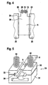
- FIG. 4 shows a test element with a taper near the sample application site.
- test element is tapered at one end 28 in the region of the sample application location 10.
- the taper 29 has the shape of a cutback, which is selected so that at maximum spread of the sample 12 of the wide portion 30 of the test element 5 is not wetted by the sample 12.
- FIG. 5 shows a two-part test element holder 19 with compression springs in an analysis system according to the invention.
- the test element holder 19 comprises a lower part 31 and an upper part 32, which are superposed and laterally secured against displacement. At the upper part 32 engage two compression springs 33 which exert on the upper part 32 of a force in the direction of the lower part 31.
- a test element 5 can be inserted in the insertion direction 6 and the two parts 31, 32 are then pushed apart by the test element 5 and the test element 5 fits into the guide element 20 without play Pressure of the compression springs 33, the test element 5 can be additionally fixed in a desired position in the guide member 20.
- the test element holder 19 On the side where a test element 5 can be inserted into the test element holder 19 (in FIG. 5 the back side, not shown), the test element holder 19 preferably has a ramp-shaped or funnel-shaped insertion opening, through which the test element 5 can be pushed into the guide element 20. This insertion opening facilitates the insertion of a test element 5, which is higher than the inner height of the guide member 20 prior to insertion of the test element 5.
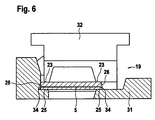
- FIG. 6 shows a two-part test element holder with inclined guide surfaces.
- the test element holder 19 comprises a lower part 31 and an upper part 32, between which a test element 5 can be inserted into a guide element 20.
- the guide member 20 has support surfaces 25, on which the test element 5 rests with support surfaces in its outer region 23, and guide surfaces 26, on which the side surfaces 34 of the test element are guided along.
- the guide surfaces 26 are arranged obliquely with respect to the side surfaces 34 of the test element 5, in order to avoid contamination of the guide surfaces 26 by the side surfaces 34 (eg by adhesive adhering thereto).
Landscapes
- Health & Medical Sciences (AREA)
- Life Sciences & Earth Sciences (AREA)
- Engineering & Computer Science (AREA)
- Physics & Mathematics (AREA)
- Biomedical Technology (AREA)
- Chemical & Material Sciences (AREA)
- Pathology (AREA)
- Analytical Chemistry (AREA)
- Immunology (AREA)
- Molecular Biology (AREA)
- General Physics & Mathematics (AREA)
- General Health & Medical Sciences (AREA)
- Biochemistry (AREA)
- Biophysics (AREA)
- Medicinal Chemistry (AREA)
- Food Science & Technology (AREA)
- Urology & Nephrology (AREA)
- Hematology (AREA)
- Optics & Photonics (AREA)
- Automatic Analysis And Handling Materials Therefor (AREA)
- Sampling And Sample Adjustment (AREA)
- Investigating Or Analysing Biological Materials (AREA)
- Optical Measuring Cells (AREA)
- Analysing Materials By The Use Of Radiation (AREA)
Priority Applications (1)
| Application Number | Priority Date | Filing Date | Title |
|---|---|---|---|
| PL05016248T PL1621885T3 (pl) | 2004-07-28 | 2005-07-26 | Układ analizujący z uchwytem elementu testowego |
Applications Claiming Priority (1)
| Application Number | Priority Date | Filing Date | Title |
|---|---|---|---|
| DE102004036474A DE102004036474A1 (de) | 2004-07-28 | 2004-07-28 | Analysesystem zur Analyse einer Probe auf einem Testelement |
Publications (4)
| Publication Number | Publication Date |
|---|---|
| EP1621885A2 EP1621885A2 (de) | 2006-02-01 |
| EP1621885A8 EP1621885A8 (de) | 2008-04-23 |
| EP1621885A3 EP1621885A3 (de) | 2010-06-02 |
| EP1621885B1 true EP1621885B1 (de) | 2012-02-01 |
Family
ID=35295747
Family Applications (1)
| Application Number | Title | Priority Date | Filing Date |
|---|---|---|---|
| EP05016248A Expired - Lifetime EP1621885B1 (de) | 2004-07-28 | 2005-07-26 | Analysesystem mit Testelementhalter |
Country Status (8)
| Country | Link |
|---|---|
| US (2) | US8318106B2 (pl) |
| EP (1) | EP1621885B1 (pl) |
| JP (1) | JP2006038857A (pl) |
| AT (1) | ATE544068T1 (pl) |
| CA (1) | CA2511204A1 (pl) |
| DE (1) | DE102004036474A1 (pl) |
| ES (1) | ES2381673T3 (pl) |
| PL (1) | PL1621885T3 (pl) |
Families Citing this family (8)
| Publication number | Priority date | Publication date | Assignee | Title |
|---|---|---|---|---|
| EP1626269B1 (en) * | 2003-05-21 | 2012-03-07 | Terumo Kabushiki Kaisha | Component measuring device |
| DE102004036474A1 (de) * | 2004-07-28 | 2006-03-23 | Roche Diagnostics Gmbh | Analysesystem zur Analyse einer Probe auf einem Testelement |
| WO2009019854A1 (ja) * | 2007-08-03 | 2009-02-12 | Panasonic Corporation | 血液検査装置及び検査方法 |
| CN108021549B (zh) | 2016-11-04 | 2019-08-13 | 华为技术有限公司 | 序列转换方法及装置 |
| CN106771278A (zh) * | 2016-12-03 | 2017-05-31 | 百奥森(江苏)食品安全科技有限公司 | 一种全自动尿检仪用尿液试纸条 |
| WO2022264719A1 (ja) | 2021-06-17 | 2022-12-22 | テルモ株式会社 | 成分測定システム及び成分測定装置 |
| JP1706794S (ja) | 2021-06-17 | 2022-02-03 | 血糖テストストリップ | |
| CA3167468C (en) * | 2022-03-15 | 2025-11-18 | Zhejiang Orient Gene Biotech Co., Ltd. | DEVICE FOR DETECTING AN ANALYTE IN A LIQUID SAMPLE |
Citations (1)
| Publication number | Priority date | Publication date | Assignee | Title |
|---|---|---|---|---|
| EP1256798A1 (en) * | 2000-11-30 | 2002-11-13 | Matsushita Electric Industrial Co., Ltd. | Biosensor, measuring instrument for biosensor, and method of quantifying substrate |
Family Cites Families (23)
| Publication number | Priority date | Publication date | Assignee | Title |
|---|---|---|---|---|
| DE2446968A1 (de) | 1974-10-02 | 1976-04-08 | Ludwig Clarius Wolfgang Dipl P | Transparentes teststreifenbuendel und mehrfachkuevette sowie verfahren zur analyse chemischer loesungen |
| JPS6113160A (ja) | 1984-06-28 | 1986-01-21 | Konishiroku Photo Ind Co Ltd | 生化学分析装置 |
| US5104619A (en) * | 1990-01-24 | 1992-04-14 | Gds Technology, Inc. | Disposable diagnostic system |
| US5232668A (en) * | 1991-02-27 | 1993-08-03 | Boehringer Mannheim Corporation | Test strip holding and reading mechanism for a meter |
| DE4310583A1 (de) * | 1993-03-31 | 1994-10-06 | Boehringer Mannheim Gmbh | Teststreifenanalysesystem |
| US5762770A (en) | 1994-02-21 | 1998-06-09 | Boehringer Mannheim Corporation | Electrochemical biosensor test strip |
| US5728352A (en) * | 1994-11-14 | 1998-03-17 | Advanced Care Products | Disposable electronic diagnostic instrument |
| DE19611347A1 (de) | 1996-03-22 | 1997-09-25 | Boehringer Mannheim Gmbh | System zur quantitativen ortsaufgelösten Auswertung von Testelementen |
| DE19629656A1 (de) * | 1996-07-23 | 1998-01-29 | Boehringer Mannheim Gmbh | Diagnostischer Testträger mit mehrschichtigem Testfeld und Verfahren zur Bestimmung von Analyt mit dessen Hilfe |
| DE19629657A1 (de) * | 1996-07-23 | 1998-01-29 | Boehringer Mannheim Gmbh | Volumenunabhängiger diagnostischer Testträger und Verfahren zur Bestimmung von Analyt mit dessen Hilfe |
| ATE230115T1 (de) * | 1996-10-30 | 2003-01-15 | Amira Medical | Sycronisiertes analyttestsystem |
| DE19753847A1 (de) | 1997-12-04 | 1999-06-10 | Roche Diagnostics Gmbh | Analytisches Testelement mit Kapillarkanal |
| DE19755529A1 (de) * | 1997-12-13 | 1999-06-17 | Roche Diagnostics Gmbh | Analysensystem für Probenflüssigkeiten |
| DE19822770B4 (de) * | 1998-05-20 | 2012-04-12 | Lre Technology Partner Gmbh | Teststreifensystem |
| DE19844500A1 (de) | 1998-09-29 | 2000-03-30 | Roche Diagnostics Gmbh | Verfahren zur photometrischen Auswertung von Testelementen |
| DE19902601A1 (de) | 1999-01-23 | 2000-07-27 | Roche Diagnostics Gmbh | Verfahren und Vorrichtung zum Entnehmen analytischer Verbrauchsmittel aus einem Vorratsbehältnis |
| US6239445B1 (en) | 1999-03-01 | 2001-05-29 | Bayer Corporation | Optical inspection apparatus with removable inserts |
| DE19912365A1 (de) | 1999-03-19 | 2000-09-21 | Roche Diagnostics Gmbh | Mehrschichtiges analytisches Hilfsmittel |
| DE10061336A1 (de) * | 2000-12-08 | 2002-06-13 | Roche Diagnostics Gmbh | System zur Analyse von Probeflüssigkeiten beinhaltend eine Lagekontrolleinheit |
| ES2320871T3 (es) | 2002-07-18 | 2009-05-29 | Panasonic Corporation | Aparato de medicion con un biosensor. |
| EP1416274B1 (de) * | 2002-10-29 | 2008-05-21 | Roche Diagnostics GmbH | Testelementanalysesystem |
| DE102004022757B4 (de) * | 2004-05-07 | 2006-11-02 | Lre Technology Partner Gmbh | Streifenauswerfer |
| DE102004036474A1 (de) * | 2004-07-28 | 2006-03-23 | Roche Diagnostics Gmbh | Analysesystem zur Analyse einer Probe auf einem Testelement |
-
2004
- 2004-07-28 DE DE102004036474A patent/DE102004036474A1/de not_active Ceased
-
2005
- 2005-06-30 CA CA002511204A patent/CA2511204A1/en not_active Abandoned
- 2005-07-22 JP JP2005212432A patent/JP2006038857A/ja active Pending
- 2005-07-26 AT AT05016248T patent/ATE544068T1/de active
- 2005-07-26 PL PL05016248T patent/PL1621885T3/pl unknown
- 2005-07-26 US US11/189,668 patent/US8318106B2/en not_active Expired - Fee Related
- 2005-07-26 EP EP05016248A patent/EP1621885B1/de not_active Expired - Lifetime
- 2005-07-26 ES ES05016248T patent/ES2381673T3/es not_active Expired - Lifetime
-
2012
- 2012-10-26 US US13/662,234 patent/US8597589B2/en not_active Expired - Fee Related
Patent Citations (1)
| Publication number | Priority date | Publication date | Assignee | Title |
|---|---|---|---|---|
| EP1256798A1 (en) * | 2000-11-30 | 2002-11-13 | Matsushita Electric Industrial Co., Ltd. | Biosensor, measuring instrument for biosensor, and method of quantifying substrate |
Also Published As
| Publication number | Publication date |
|---|---|
| ES2381673T3 (es) | 2012-05-30 |
| EP1621885A2 (de) | 2006-02-01 |
| US8318106B2 (en) | 2012-11-27 |
| US20130052082A1 (en) | 2013-02-28 |
| US20060024203A1 (en) | 2006-02-02 |
| EP1621885A3 (de) | 2010-06-02 |
| ATE544068T1 (de) | 2012-02-15 |
| US8597589B2 (en) | 2013-12-03 |
| CA2511204A1 (en) | 2006-01-28 |
| PL1621885T3 (pl) | 2012-07-31 |
| JP2006038857A (ja) | 2006-02-09 |
| EP1621885A8 (de) | 2008-04-23 |
| DE102004036474A1 (de) | 2006-03-23 |
Similar Documents
| Publication | Publication Date | Title |
|---|---|---|
| DE69128700T2 (de) | Vorrichtung zur quantitativen Entnahme von Flüssigkeitsproben | |
| EP0816831B1 (de) | Teststreifenauswertegerät | |
| EP0922959B1 (de) | Analysensystem für Probenflüssigkeiten | |
| EP1574855B1 (de) | Analysehandgerät | |
| EP3162443B1 (de) | Nadelführung mit zentrierung für septum-piercing | |
| DE4313253A1 (de) | System zur Analyse von Inhaltsstoffen flüssiger Proben | |
| DE112015001461T5 (de) | Mikroskopbetrachtungsbehälter und Betrachtungsvorrichtung | |
| US8597589B2 (en) | Analysis system for analyzing a sample on a test element | |
| EP1984729A1 (de) | Verfahren und vorrichtung zum ansaugen eines flüssigkeitsvolumens, insbesondere zur entnahme einer probe zur analyse mittels einer flüssigkeitschromatographievorrichtung | |
| EP3270167B1 (de) | Transport von flüssigkeitsbehältern in einem automatischen analysegerät | |
| EP1995594B1 (de) | Analysehandgerät zum Untersuchen einer Probe | |
| EP1416274B1 (de) | Testelementanalysesystem | |
| EP4091715A1 (de) | Teststreifenanordnung mit behältern | |
| EP2389097B1 (de) | System und verfahren zur analyse einer körperflüssigkeit | |
| EP1508807B1 (de) | Positioniereinrichtung für ein Testelement | |
| EP2754492A1 (de) | Verschlussvorrichtung für einen Zugang zu einem Behälter für Reagenzgefässe in einem automatischen Analysegerät | |
| EP3361253A1 (de) | Vorrichtung zur gezielten prüfung und anzeige der ab- bzw. anwesenheit von analyten in einer flüssigen probe | |
| EP1189064B1 (de) | Verfahren zum Kontrollieren der Gebrauchstauglichkeit von Analyseelementen | |
| EP1672364B1 (de) | Analysesystem zur Analyse einer flüssigen Probe auf einem analytischen Testelement | |
| EP3699599A1 (de) | Abfallverbringungssystem | |
| WO2013060483A2 (de) | Verfahren und vorrichtung zur kontrolle des volumens und der zusammensetzung mindestens einer probe | |
| EP3196649A1 (de) | Justagesystem | |
| WO2022263036A1 (de) | Mikrofluidischer chip | |
| DE3878963T2 (de) | Verfahren zur chemischen analysierung unter verwendung einer testvorrichtung einer probe. | |
| EP3418750A1 (de) | Ermittlung von füllständen in gefässen |
Legal Events
| Date | Code | Title | Description |
|---|---|---|---|
| PUAI | Public reference made under article 153(3) epc to a published international application that has entered the european phase |
Free format text: ORIGINAL CODE: 0009012 |
|
| AK | Designated contracting states |
Kind code of ref document: A2 Designated state(s): AT BE BG CH CY CZ DE DK EE ES FI FR GB GR HU IE IS IT LI LT LU LV MC NL PL PT RO SE SI SK TR |
|
| AX | Request for extension of the european patent |
Extension state: AL BA HR MK YU |
|
| RAP1 | Party data changed (applicant data changed or rights of an application transferred) |
Owner name: ROCHE DIAGNOSTICS GMBH Owner name: F.HOFFMANN-LA ROCHE AG |
|
| RIN1 | Information on inventor provided before grant (corrected) |
Inventor name: RINGELSPACHER, YVONNE Inventor name: SCHULAT, JOCHEN Inventor name: JANSEN, PAUL |
|
| PUAL | Search report despatched |
Free format text: ORIGINAL CODE: 0009013 |
|
| AK | Designated contracting states |
Kind code of ref document: A3 Designated state(s): AT BE BG CH CY CZ DE DK EE ES FI FR GB GR HU IE IS IT LI LT LU LV MC NL PL PT RO SE SI SK TR |
|
| AX | Request for extension of the european patent |
Extension state: AL BA HR MK YU |
|
| RIC1 | Information provided on ipc code assigned before grant |
Ipc: G01N 33/487 20060101AFI20051118BHEP Ipc: G01N 21/86 20060101ALI20100427BHEP |
|
| 17P | Request for examination filed |
Effective date: 20100714 |
|
| 17Q | First examination report despatched |
Effective date: 20100809 |
|
| AKX | Designation fees paid |
Designated state(s): AT BE BG CH CY CZ DE DK EE ES FI FR GB GR HU IE IS IT LI LT LU LV MC NL PL PT RO SE SI SK TR |
|
| GRAP | Despatch of communication of intention to grant a patent |
Free format text: ORIGINAL CODE: EPIDOSNIGR1 |
|
| RIC1 | Information provided on ipc code assigned before grant |
Ipc: G01N 33/487 20060101AFI20110727BHEP Ipc: G01N 21/86 20060101ALI20110727BHEP |
|
| RIN1 | Information on inventor provided before grant (corrected) |
Inventor name: SCHULAT, JOCHEN Inventor name: RINGELSPACHER, YVONNE Inventor name: JANSEN, PAUL |
|
| GRAS | Grant fee paid |
Free format text: ORIGINAL CODE: EPIDOSNIGR3 |
|
| GRAA | (expected) grant |
Free format text: ORIGINAL CODE: 0009210 |
|
| AK | Designated contracting states |
Kind code of ref document: B1 Designated state(s): AT BE BG CH CY CZ DE DK EE ES FI FR GB GR HU IE IS IT LI LT LU LV MC NL PL PT RO SE SI SK TR |
|
| REG | Reference to a national code |
Ref country code: GB Ref legal event code: FG4D Free format text: NOT ENGLISH |
|
| REG | Reference to a national code |
Ref country code: DE Ref legal event code: R081 Ref document number: 502005012406 Country of ref document: DE Owner name: ROCHE DIABETES CARE GMBH, DE Free format text: FORMER OWNERS: ROCHE DIAGNOSTICS GMBH, 68305 MANNHEIM, DE; F. HOFFMANN-LA ROCHE AG, 4070 BASEL, CH |
|
| REG | Reference to a national code |
Ref country code: AT Ref legal event code: REF Ref document number: 544068 Country of ref document: AT Kind code of ref document: T Effective date: 20120215 Ref country code: CH Ref legal event code: EP |
|
| REG | Reference to a national code |
Ref country code: DE Ref legal event code: R096 Ref document number: 502005012406 Country of ref document: DE Effective date: 20120329 |
|
| REG | Reference to a national code |
Ref country code: NL Ref legal event code: T3 |
|
| REG | Reference to a national code |
Ref country code: ES Ref legal event code: FG2A Ref document number: 2381673 Country of ref document: ES Kind code of ref document: T3 Effective date: 20120530 |
|
| LTIE | Lt: invalidation of european patent or patent extension |
Effective date: 20120201 |
|
| PG25 | Lapsed in a contracting state [announced via postgrant information from national office to epo] |
Ref country code: LT Free format text: LAPSE BECAUSE OF FAILURE TO SUBMIT A TRANSLATION OF THE DESCRIPTION OR TO PAY THE FEE WITHIN THE PRESCRIBED TIME-LIMIT Effective date: 20120201 Ref country code: IS Free format text: LAPSE BECAUSE OF FAILURE TO SUBMIT A TRANSLATION OF THE DESCRIPTION OR TO PAY THE FEE WITHIN THE PRESCRIBED TIME-LIMIT Effective date: 20120601 |
|
| REG | Reference to a national code |
Ref country code: PL Ref legal event code: T3 |
|
| REG | Reference to a national code |
Ref country code: IE Ref legal event code: FD4D |
|
| PG25 | Lapsed in a contracting state [announced via postgrant information from national office to epo] |
Ref country code: GR Free format text: LAPSE BECAUSE OF FAILURE TO SUBMIT A TRANSLATION OF THE DESCRIPTION OR TO PAY THE FEE WITHIN THE PRESCRIBED TIME-LIMIT Effective date: 20120502 Ref country code: FI Free format text: LAPSE BECAUSE OF FAILURE TO SUBMIT A TRANSLATION OF THE DESCRIPTION OR TO PAY THE FEE WITHIN THE PRESCRIBED TIME-LIMIT Effective date: 20120201 Ref country code: LV Free format text: LAPSE BECAUSE OF FAILURE TO SUBMIT A TRANSLATION OF THE DESCRIPTION OR TO PAY THE FEE WITHIN THE PRESCRIBED TIME-LIMIT Effective date: 20120201 Ref country code: PT Free format text: LAPSE BECAUSE OF FAILURE TO SUBMIT A TRANSLATION OF THE DESCRIPTION OR TO PAY THE FEE WITHIN THE PRESCRIBED TIME-LIMIT Effective date: 20120601 |
|
| PG25 | Lapsed in a contracting state [announced via postgrant information from national office to epo] |
Ref country code: CY Free format text: LAPSE BECAUSE OF FAILURE TO SUBMIT A TRANSLATION OF THE DESCRIPTION OR TO PAY THE FEE WITHIN THE PRESCRIBED TIME-LIMIT Effective date: 20120201 |
|
| PG25 | Lapsed in a contracting state [announced via postgrant information from national office to epo] |
Ref country code: DK Free format text: LAPSE BECAUSE OF FAILURE TO SUBMIT A TRANSLATION OF THE DESCRIPTION OR TO PAY THE FEE WITHIN THE PRESCRIBED TIME-LIMIT Effective date: 20120201 Ref country code: SI Free format text: LAPSE BECAUSE OF FAILURE TO SUBMIT A TRANSLATION OF THE DESCRIPTION OR TO PAY THE FEE WITHIN THE PRESCRIBED TIME-LIMIT Effective date: 20120201 Ref country code: IE Free format text: LAPSE BECAUSE OF FAILURE TO SUBMIT A TRANSLATION OF THE DESCRIPTION OR TO PAY THE FEE WITHIN THE PRESCRIBED TIME-LIMIT Effective date: 20120201 Ref country code: CZ Free format text: LAPSE BECAUSE OF FAILURE TO SUBMIT A TRANSLATION OF THE DESCRIPTION OR TO PAY THE FEE WITHIN THE PRESCRIBED TIME-LIMIT Effective date: 20120201 Ref country code: EE Free format text: LAPSE BECAUSE OF FAILURE TO SUBMIT A TRANSLATION OF THE DESCRIPTION OR TO PAY THE FEE WITHIN THE PRESCRIBED TIME-LIMIT Effective date: 20120201 Ref country code: RO Free format text: LAPSE BECAUSE OF FAILURE TO SUBMIT A TRANSLATION OF THE DESCRIPTION OR TO PAY THE FEE WITHIN THE PRESCRIBED TIME-LIMIT Effective date: 20120201 Ref country code: SE Free format text: LAPSE BECAUSE OF FAILURE TO SUBMIT A TRANSLATION OF THE DESCRIPTION OR TO PAY THE FEE WITHIN THE PRESCRIBED TIME-LIMIT Effective date: 20120201 |
|
| PG25 | Lapsed in a contracting state [announced via postgrant information from national office to epo] |
Ref country code: SK Free format text: LAPSE BECAUSE OF FAILURE TO SUBMIT A TRANSLATION OF THE DESCRIPTION OR TO PAY THE FEE WITHIN THE PRESCRIBED TIME-LIMIT Effective date: 20120201 |
|
| PLBE | No opposition filed within time limit |
Free format text: ORIGINAL CODE: 0009261 |
|
| STAA | Information on the status of an ep patent application or granted ep patent |
Free format text: STATUS: NO OPPOSITION FILED WITHIN TIME LIMIT |
|
| 26N | No opposition filed |
Effective date: 20121105 |
|
| BERE | Be: lapsed |
Owner name: ROCHE DIAGNOSTICS G.M.B.H. Effective date: 20120731 Owner name: F.HOFFMANN-LA ROCHE A.G. Effective date: 20120731 |
|
| PG25 | Lapsed in a contracting state [announced via postgrant information from national office to epo] |
Ref country code: MC Free format text: LAPSE BECAUSE OF NON-PAYMENT OF DUE FEES Effective date: 20120731 |
|
| REG | Reference to a national code |
Ref country code: CH Ref legal event code: PL Ref country code: DE Ref legal event code: R097 Ref document number: 502005012406 Country of ref document: DE Effective date: 20121105 |
|
| PG25 | Lapsed in a contracting state [announced via postgrant information from national office to epo] |
Ref country code: LI Free format text: LAPSE BECAUSE OF NON-PAYMENT OF DUE FEES Effective date: 20120731 Ref country code: CH Free format text: LAPSE BECAUSE OF NON-PAYMENT OF DUE FEES Effective date: 20120731 |
|
| PG25 | Lapsed in a contracting state [announced via postgrant information from national office to epo] |
Ref country code: BE Free format text: LAPSE BECAUSE OF NON-PAYMENT OF DUE FEES Effective date: 20120731 |
|
| PG25 | Lapsed in a contracting state [announced via postgrant information from national office to epo] |
Ref country code: BG Free format text: LAPSE BECAUSE OF FAILURE TO SUBMIT A TRANSLATION OF THE DESCRIPTION OR TO PAY THE FEE WITHIN THE PRESCRIBED TIME-LIMIT Effective date: 20120501 |
|
| REG | Reference to a national code |
Ref country code: AT Ref legal event code: MM01 Ref document number: 544068 Country of ref document: AT Kind code of ref document: T Effective date: 20120731 |
|
| PG25 | Lapsed in a contracting state [announced via postgrant information from national office to epo] |
Ref country code: AT Free format text: LAPSE BECAUSE OF NON-PAYMENT OF DUE FEES Effective date: 20120731 |
|
| PG25 | Lapsed in a contracting state [announced via postgrant information from national office to epo] |
Ref country code: TR Free format text: LAPSE BECAUSE OF FAILURE TO SUBMIT A TRANSLATION OF THE DESCRIPTION OR TO PAY THE FEE WITHIN THE PRESCRIBED TIME-LIMIT Effective date: 20120201 |
|
| PG25 | Lapsed in a contracting state [announced via postgrant information from national office to epo] |
Ref country code: LU Free format text: LAPSE BECAUSE OF NON-PAYMENT OF DUE FEES Effective date: 20120726 |
|
| PG25 | Lapsed in a contracting state [announced via postgrant information from national office to epo] |
Ref country code: HU Free format text: LAPSE BECAUSE OF FAILURE TO SUBMIT A TRANSLATION OF THE DESCRIPTION OR TO PAY THE FEE WITHIN THE PRESCRIBED TIME-LIMIT Effective date: 20050726 |
|
| REG | Reference to a national code |
Ref country code: DE Ref legal event code: R081 Ref document number: 502005012406 Country of ref document: DE Owner name: ROCHE DIABETES CARE GMBH, DE Free format text: FORMER OWNER: ROCHE DIAGNOSTICS GMBH, 68305 MANNHEIM, DE |
|
| REG | Reference to a national code |
Ref country code: FR Ref legal event code: PLFP Year of fee payment: 12 |
|
| REG | Reference to a national code |
Ref country code: FR Ref legal event code: PLFP Year of fee payment: 13 |
|
| PGFP | Annual fee paid to national office [announced via postgrant information from national office to epo] |
Ref country code: FR Payment date: 20170621 Year of fee payment: 13 Ref country code: GB Payment date: 20170626 Year of fee payment: 13 |
|
| PGFP | Annual fee paid to national office [announced via postgrant information from national office to epo] |
Ref country code: PL Payment date: 20170621 Year of fee payment: 13 |
|
| PGFP | Annual fee paid to national office [announced via postgrant information from national office to epo] |
Ref country code: NL Payment date: 20170714 Year of fee payment: 13 |
|
| PGFP | Annual fee paid to national office [announced via postgrant information from national office to epo] |
Ref country code: GB Payment date: 20170822 Year of fee payment: 13 Ref country code: ES Payment date: 20170808 Year of fee payment: 13 |
|
| REG | Reference to a national code |
Ref country code: NL Ref legal event code: MM Effective date: 20180801 |
|
| GBPC | Gb: european patent ceased through non-payment of renewal fee |
Effective date: 20180726 |
|
| PG25 | Lapsed in a contracting state [announced via postgrant information from national office to epo] |
Ref country code: FR Free format text: LAPSE BECAUSE OF NON-PAYMENT OF DUE FEES Effective date: 20180731 Ref country code: GB Free format text: LAPSE BECAUSE OF NON-PAYMENT OF DUE FEES Effective date: 20180726 |
|
| PG25 | Lapsed in a contracting state [announced via postgrant information from national office to epo] |
Ref country code: NL Free format text: LAPSE BECAUSE OF NON-PAYMENT OF DUE FEES Effective date: 20180801 |
|
| PG25 | Lapsed in a contracting state [announced via postgrant information from national office to epo] |
Ref country code: IT Free format text: LAPSE BECAUSE OF NON-PAYMENT OF DUE FEES Effective date: 20180726 |
|
| REG | Reference to a national code |
Ref country code: ES Ref legal event code: FD2A Effective date: 20190917 |
|
| PG25 | Lapsed in a contracting state [announced via postgrant information from national office to epo] |
Ref country code: ES Free format text: LAPSE BECAUSE OF NON-PAYMENT OF DUE FEES Effective date: 20180727 |
|
| PG25 | Lapsed in a contracting state [announced via postgrant information from national office to epo] |
Ref country code: PL Free format text: LAPSE BECAUSE OF NON-PAYMENT OF DUE FEES Effective date: 20180726 |
|
| PGFP | Annual fee paid to national office [announced via postgrant information from national office to epo] |
Ref country code: DE Payment date: 20210616 Year of fee payment: 17 |
|
| REG | Reference to a national code |
Ref country code: DE Ref legal event code: R119 Ref document number: 502005012406 Country of ref document: DE |
|
| PG25 | Lapsed in a contracting state [announced via postgrant information from national office to epo] |
Ref country code: DE Free format text: LAPSE BECAUSE OF NON-PAYMENT OF DUE FEES Effective date: 20230201 |