EP1620683B1 - Systeme de surveillance de gaz et systeme de mesure de courant gazeux lateral conçu pour communiquer avec un systeme de mesure de courant gazeux principal - Google Patents
Systeme de surveillance de gaz et systeme de mesure de courant gazeux lateral conçu pour communiquer avec un systeme de mesure de courant gazeux principal Download PDFInfo
- Publication number
- EP1620683B1 EP1620683B1 EP04712927A EP04712927A EP1620683B1 EP 1620683 B1 EP1620683 B1 EP 1620683B1 EP 04712927 A EP04712927 A EP 04712927A EP 04712927 A EP04712927 A EP 04712927A EP 1620683 B1 EP1620683 B1 EP 1620683B1
- Authority
- EP
- European Patent Office
- Prior art keywords
- gas
- measurement system
- gas measurement
- sample cell
- mainstream
- Prior art date
- Legal status (The legal status is an assumption and is not a legal conclusion. Google has not performed a legal analysis and makes no representation as to the accuracy of the status listed.)
- Expired - Lifetime
Links
- 238000005259 measurement Methods 0.000 title claims abstract description 172
- 238000012544 monitoring process Methods 0.000 title claims description 31
- 230000000241 respiratory effect Effects 0.000 claims description 39
- 230000008878 coupling Effects 0.000 claims description 29
- 238000010168 coupling process Methods 0.000 claims description 29
- 238000005859 coupling reaction Methods 0.000 claims description 29
- 238000004891 communication Methods 0.000 claims description 27
- 238000000034 method Methods 0.000 claims description 16
- 238000012545 processing Methods 0.000 claims description 16
- 239000012530 fluid Substances 0.000 claims description 5
- 239000007789 gas Substances 0.000 description 287
- CURLTUGMZLYLDI-UHFFFAOYSA-N Carbon dioxide Chemical compound O=C=O CURLTUGMZLYLDI-UHFFFAOYSA-N 0.000 description 18
- 238000005070 sampling Methods 0.000 description 15
- 239000000470 constituent Substances 0.000 description 14
- 230000029058 respiratory gaseous exchange Effects 0.000 description 14
- 230000006870 function Effects 0.000 description 11
- 229910002092 carbon dioxide Inorganic materials 0.000 description 10
- 239000001569 carbon dioxide Substances 0.000 description 8
- 238000010586 diagram Methods 0.000 description 6
- MWUXSHHQAYIFBG-UHFFFAOYSA-N Nitric oxide Chemical compound O=[N] MWUXSHHQAYIFBG-UHFFFAOYSA-N 0.000 description 4
- 238000004458 analytical method Methods 0.000 description 4
- 230000008901 benefit Effects 0.000 description 4
- 230000002452 interceptive effect Effects 0.000 description 4
- 230000003287 optical effect Effects 0.000 description 4
- 230000005855 radiation Effects 0.000 description 4
- 238000013459 approach Methods 0.000 description 3
- 239000000356 contaminant Substances 0.000 description 3
- 238000005516 engineering process Methods 0.000 description 3
- GQPLMRYTRLFLPF-UHFFFAOYSA-N Nitrous Oxide Chemical compound [O-][N+]#N GQPLMRYTRLFLPF-UHFFFAOYSA-N 0.000 description 2
- 230000008859 change Effects 0.000 description 2
- 238000011109 contamination Methods 0.000 description 2
- 238000001514 detection method Methods 0.000 description 2
- 238000011156 evaluation Methods 0.000 description 2
- 238000010438 heat treatment Methods 0.000 description 2
- 239000007788 liquid Substances 0.000 description 2
- 238000004519 manufacturing process Methods 0.000 description 2
- 238000012986 modification Methods 0.000 description 2
- 230000004048 modification Effects 0.000 description 2
- 230000004044 response Effects 0.000 description 2
- 230000002000 scavenging effect Effects 0.000 description 2
- 238000002834 transmittance Methods 0.000 description 2
- 230000032258 transport Effects 0.000 description 2
- 206010002091 Anaesthesia Diseases 0.000 description 1
- 235000009421 Myristica fragrans Nutrition 0.000 description 1
- 238000010521 absorption reaction Methods 0.000 description 1
- 230000002411 adverse Effects 0.000 description 1
- 230000037005 anaesthesia Effects 0.000 description 1
- QVGXLLKOCUKJST-UHFFFAOYSA-N atomic oxygen Chemical compound [O] QVGXLLKOCUKJST-UHFFFAOYSA-N 0.000 description 1
- 238000009530 blood pressure measurement Methods 0.000 description 1
- 239000003795 chemical substances by application Substances 0.000 description 1
- 230000005494 condensation Effects 0.000 description 1
- 238000009833 condensation Methods 0.000 description 1
- 239000004020 conductor Substances 0.000 description 1
- 230000001351 cycling effect Effects 0.000 description 1
- 238000013461 design Methods 0.000 description 1
- 201000010099 disease Diseases 0.000 description 1
- 208000037265 diseases, disorders, signs and symptoms Diseases 0.000 description 1
- 229940079593 drug Drugs 0.000 description 1
- 239000003814 drug Substances 0.000 description 1
- 230000000694 effects Effects 0.000 description 1
- 229940124645 emergency medicine Drugs 0.000 description 1
- 229940003953 helium / oxygen Drugs 0.000 description 1
- 239000001115 mace Substances 0.000 description 1
- 238000005399 mechanical ventilation Methods 0.000 description 1
- 239000000203 mixture Substances 0.000 description 1
- 239000001272 nitrous oxide Substances 0.000 description 1
- 239000001301 oxygen Substances 0.000 description 1
- 229910052760 oxygen Inorganic materials 0.000 description 1
- 230000035790 physiological processes and functions Effects 0.000 description 1
- 230000008569 process Effects 0.000 description 1
- 230000009467 reduction Effects 0.000 description 1
- 230000001105 regulatory effect Effects 0.000 description 1
- 230000003068 static effect Effects 0.000 description 1
- 239000000126 substance Substances 0.000 description 1
- 239000013589 supplement Substances 0.000 description 1
- 238000002560 therapeutic procedure Methods 0.000 description 1
- 210000003437 trachea Anatomy 0.000 description 1
- 238000002627 tracheal intubation Methods 0.000 description 1
- XLYOFNOQVPJJNP-UHFFFAOYSA-N water Substances O XLYOFNOQVPJJNP-UHFFFAOYSA-N 0.000 description 1
Images

Classifications
-
- A—HUMAN NECESSITIES
- A61—MEDICAL OR VETERINARY SCIENCE; HYGIENE
- A61B—DIAGNOSIS; SURGERY; IDENTIFICATION
- A61B5/00—Measuring for diagnostic purposes; Identification of persons
- A61B5/08—Detecting, measuring or recording devices for evaluating the respiratory organs
- A61B5/087—Measuring breath flow
-
- A—HUMAN NECESSITIES
- A61—MEDICAL OR VETERINARY SCIENCE; HYGIENE
- A61B—DIAGNOSIS; SURGERY; IDENTIFICATION
- A61B5/00—Measuring for diagnostic purposes; Identification of persons
- A61B5/08—Detecting, measuring or recording devices for evaluating the respiratory organs
- A61B5/083—Measuring rate of metabolism by using breath test, e.g. measuring rate of oxygen consumption
-
- G—PHYSICS
- G01—MEASURING; TESTING
- G01N—INVESTIGATING OR ANALYSING MATERIALS BY DETERMINING THEIR CHEMICAL OR PHYSICAL PROPERTIES
- G01N21/00—Investigating or analysing materials by the use of optical means, i.e. using sub-millimetre waves, infrared, visible or ultraviolet light
- G01N21/17—Systems in which incident light is modified in accordance with the properties of the material investigated
- G01N21/25—Colour; Spectral properties, i.e. comparison of effect of material on the light at two or more different wavelengths or wavelength bands
- G01N21/31—Investigating relative effect of material at wavelengths characteristic of specific elements or molecules, e.g. atomic absorption spectrometry
- G01N21/35—Investigating relative effect of material at wavelengths characteristic of specific elements or molecules, e.g. atomic absorption spectrometry using infrared light
- G01N21/3504—Investigating relative effect of material at wavelengths characteristic of specific elements or molecules, e.g. atomic absorption spectrometry using infrared light for analysing gases, e.g. multi-gas analysis
-
- A—HUMAN NECESSITIES
- A61—MEDICAL OR VETERINARY SCIENCE; HYGIENE
- A61B—DIAGNOSIS; SURGERY; IDENTIFICATION
- A61B2562/00—Details of sensors; Constructional details of sensor housings or probes; Accessories for sensors
- A61B2562/22—Arrangements of medical sensors with cables or leads; Connectors or couplings specifically adapted for medical sensors
- A61B2562/225—Connectors or couplings
- A61B2562/226—Connectors or couplings comprising means for identifying the connector, e.g. to prevent incorrect connection to socket
-
- A—HUMAN NECESSITIES
- A61—MEDICAL OR VETERINARY SCIENCE; HYGIENE
- A61B—DIAGNOSIS; SURGERY; IDENTIFICATION
- A61B5/00—Measuring for diagnostic purposes; Identification of persons
- A61B5/02—Detecting, measuring or recording pulse, heart rate, blood pressure or blood flow; Combined pulse/heart-rate/blood pressure determination; Evaluating a cardiovascular condition not otherwise provided for, e.g. using combinations of techniques provided for in this group with electrocardiography or electroauscultation; Heart catheters for measuring blood pressure
- A61B5/0205—Simultaneously evaluating both cardiovascular conditions and different types of body conditions, e.g. heart and respiratory condition
-
- G—PHYSICS
- G01—MEASURING; TESTING
- G01N—INVESTIGATING OR ANALYSING MATERIALS BY DETERMINING THEIR CHEMICAL OR PHYSICAL PROPERTIES
- G01N21/00—Investigating or analysing materials by the use of optical means, i.e. using sub-millimetre waves, infrared, visible or ultraviolet light
- G01N21/01—Arrangements or apparatus for facilitating the optical investigation
- G01N2021/0106—General arrangement of respective parts
- G01N2021/0118—Apparatus with remote processing
-
- G—PHYSICS
- G01—MEASURING; TESTING
- G01N—INVESTIGATING OR ANALYSING MATERIALS BY DETERMINING THEIR CHEMICAL OR PHYSICAL PROPERTIES
- G01N21/00—Investigating or analysing materials by the use of optical means, i.e. using sub-millimetre waves, infrared, visible or ultraviolet light
- G01N21/01—Arrangements or apparatus for facilitating the optical investigation
- G01N2021/0193—Arrangements or apparatus for facilitating the optical investigation the sample being taken from a stream or flow to the measurement cell
-
- G—PHYSICS
- G01—MEASURING; TESTING
- G01N—INVESTIGATING OR ANALYSING MATERIALS BY DETERMINING THEIR CHEMICAL OR PHYSICAL PROPERTIES
- G01N21/00—Investigating or analysing materials by the use of optical means, i.e. using sub-millimetre waves, infrared, visible or ultraviolet light
- G01N21/01—Arrangements or apparatus for facilitating the optical investigation
- G01N21/03—Cuvette constructions
- G01N21/05—Flow-through cuvettes
-
- G—PHYSICS
- G01—MEASURING; TESTING
- G01N—INVESTIGATING OR ANALYSING MATERIALS BY DETERMINING THEIR CHEMICAL OR PHYSICAL PROPERTIES
- G01N2201/00—Features of devices classified in G01N21/00
- G01N2201/12—Circuits of general importance; Signal processing
- G01N2201/121—Correction signals
- G01N2201/1215—Correction signals for interfering gases
-
- G—PHYSICS
- G01—MEASURING; TESTING
- G01N—INVESTIGATING OR ANALYSING MATERIALS BY DETERMINING THEIR CHEMICAL OR PHYSICAL PROPERTIES
- G01N33/00—Investigating or analysing materials by specific methods not covered by groups G01N1/00 - G01N31/00
- G01N33/48—Biological material, e.g. blood, urine; Haemocytometers
- G01N33/483—Physical analysis of biological material
- G01N33/497—Physical analysis of biological material of gaseous biological material, e.g. breath
Definitions
- the present invention pertains to a method and apparatus for interfacing a plurality of Gas Measurement Systems to a Host System via an interface unit, and to a sidestream Gas Measurement System that is capable of communicating with a Host System that is specifically configured to communicate with only a mainstream Gas Measurement System.
- Respiratory Gas Monitoring Systems typically include gas sensing, measurement, processing, communication, and display functions. They are generally classified by operating modality as either diverting (i.e., sidestream) or non-diverting (i.e., mainstream).
- a diverting Gas Measurement System transports a portion of the sampled gases from the sampling site through a sampling tube to the Sample Cell, where the constituents of the gas are measured by a Gas Sensor.
- the sampling side is typically a in breathing circuit coupled to the patient's airway or at a location near the patient's airway.
- a non-diverting Gas Measurement System does not transport gas away from the breathing circuit or the patient's airway, but measures the gas constituents passing through a Sample Cell disposed in the breathing circuit.
- Mainstream Gas Measurement System 8 includes a Sample Cell 10 disposed in a breathing circuit 12 such that gas delivered to and/or received from the patient, as indicated by arrow A, passes through the Sample Cell.
- a Gas Sensor 14 coupled to the Sample Cell produces a detected or measured signal, e.g., a voltage, indicative of the concentration of a gas constituent in the gas sample in the Sample Cell.
- Gas Sensor 14 communicates with Sample Cell 10 placed at the breathing circuit and includes the components required to output a detected signal corresponding to a property of the gas to be measured.
- Gas Sensor 14 in a conventional mainstream Gas Measurement System that is capable of measuring carbon dioxide, Gas Sensor 14 includes a source 16 that emits infrared radiation, as indicated by arrow B, encompassing an absorption band for carbon dioxide. The infrared radiation is transmitted along a path that is normal to the flow path of the respiratory gas stream through the Sample Cell. Gas Sensor 14 in this conventional system further includes photodetectors 18 that measure the transmitted radiation. Carbon dioxide in the sample gas absorbs this radiation at some wavelengths and passes other wavelengths.
- a multi-conductor lightweight, flexible cable 20 transmits the detected signals output by photodetectors 18 to a Gas Monitor 22 from which the partial pressure of carbon dioxide CO 2 is calculated.
- the Gas Monitor is a stand-alone unit contained within a housing 26 that includes a terminal 27 to which cable 20 is selectively coupled.
- the Gas Monitor includes processing elements that convert the detected signal from the Gas Sensor into a value, such as transmittance, that is used to produce an indication of the concentration of a particular gas constituent in the gas sample within the Sample Cell. This value indicative of the concentration of the gas under analysis is provided to a Host System 24 also contained in housing 26, which uses this information in any one of a variety ways.
- the Host System may display the indication of the designated gas as a waveform or as a value in partial pressure units, such as mmHg or concentration in units, such as a percent (%).
- the Host System can use the indication to calculate other parameters, which can then be displayed or communicated to another system, such as a central station.
- the calculated CO 2 partial pressure is typically graphically displayed in the form of a capnogram via an output device serving as the Host System, such as a display provided on the exterior of the housing 26.
- Gas Monitor 22 contains the processing elements that control the operation of Gas Sensor 14 and provide the gas measurement functions to the Host System based on the output signals from the Gas Sensor.
- An example of such a conventional mainstream Gas Measurement System is shown in U.S. Patent No. 4,914,720 issued to Knodle et al .
- An advantage of a mainstream Gas Measurement System is that the placement of the Sample Cell directly at the breathing circuit results in a "crisp" gas concentration waveform that more faithfully reflects, in real-time, the varying partial pressure of the measured gas, such as carbon dioxide, within the airway that is generally possible using a sidestream approach.
- locating the Sample Cell, which is also referred to as a cuvette or airway adapter, in the respiratory gas stream obviates the need for gas sampling and scavenging as required in a sidestream Gas Measurement System.
- FIG. 2 As example of a conventional sidestream Gas Measurement System 28 is shown in FIG. 2 .
- Sidestream Gas Measurement System 28 utilizes a long sampling tube 30 connected to an adapter 32 connected in line in breathing circuit, such as a T-piece connected at the endotracheal tube or mask connector.
- a nasal canula as the gas collection element in a conventional sidestream system so that the gas is taken directly at the patient's airway.
- the sample gas is continuously aspirated from the breathing circuit or the nasal canula through sampling tube 30, as indicated by arrow C, and into a Sample Cell 10' at sample flow rates ranging from 50 to 250 ml/min.
- a pump 34 is typically provided to draw the gas into the Sample Cell from the gas sample site.
- Sample Cell 10' is contained in a housing 36, which also contains both a Gas Sensor, generally indicated at 38, and a Gas Monitor 22.
- the Gas Sensor in the sidestream Gas Measurement System includes components that provide a detected signal indicative of the concentration of a gas constituent in the gas sample in the Sample Cell, such as source 16 and emitter photodetectors 18.
- the Gas Monitor in the sidestream Gas Measurement System includes the processing elements that convert the detected signal from the Gas Sensor into a value used to produce an indication of the concentration of a particular gas constituent. This value is provided to Host System 24, where it is typically displayed on a display provided on housing 36. Examples of conventional sidestream Gas Measurement Systems are taught in U.S. Patent Nos. 4,692,621 to Passaro et al. ; 4,177,381 to McClatchie , and 5,282,473 to Braig et al .
- mainstream Gas Measurement Systems A large installed base of mainstream Gas Measurement Systems exist. However, a growing number of mainstream Gas Measurement System users desire or require the use of a sidestream Gas Measurement System. These users seek a simple and easy solution to add the sidestream gas measurement capability to their existing patient monitor inventory without having to replace completely or partially the existing mainstream Gas Measurement Systems. However, existing mainstream Gas Measurement Systems do not allow users to easily add the sidestream sampling function, because they are specifically configured for mainstream operation.
- the system taught by the '475 patent provides a mainstream type Gas Sensor coupled to the Sample Cell.
- the '475 patent teaches moving the Gas Sensor functions of a sidestream system out of the housing containing the Gas Monitor functions. It can be appreciated, that this approach still requires the use of a specialized adapter, which is connected to a pump, as well as valving, and control circuitry in the same box.
- a Respiratory Gas Monitoring System that overcomes the shortcomings of conventional gas monitoring systems.
- This object is achieved according to one embodiment of the present invention by providing a Respiratory Gas Monitoring System that includes an interface unit having an input coupling and an output. The output is adapted to communicate with a Host System in any conventional manner.
- the Respiratory Gas Monitoring System further includes a plurality of Gas Measurement Systems, each having a separate housing. Each Gas Measurement System is adapted to be placed in fluid communication with an airway of a patient to measure at least one respiratory gas.
- each Gas Measurement System has an output coupling that is adapted to be removably coupled to the input coupling of the interface unit.
- Each Gas Measurement System also includes a processor that determines, from the respiratory gas, at least one respiratory variable of a patient and provides an output to the Host System via the interface unit. It can be appreciated that this Respiratory Gas Monitoring System provides a convenient technique to interface a plurality of gas sensing technologies, e. g., sidestream, mainstream, or both, to a single interface unit, which, in turn, communicates with a Host System.
- This object is achieved by providing a method that includes providing an interface unit having an input coupling and an output and providing a plurality of Gas Measurement Systems, each having a separate housing.
- Each Gas Measurement System has an output coupling and processing elements for determining, from the respiratory gas, at least one respiratory variable of a patient.
- the method further includes the step of selectively coupling one of the plurality of Gas Measurement Systems to the interface unit by coupling the output coupling of an associated Gas Measurement System with the input coupling of the interface unit. In this manner, any type of Gas Measurement System can be coupled to a Host System via the interface device.
- FIG. 1 is a schematic diagram of a conventional mainstream Gas Measurement System
- FIG. 2 is a schematic diagram of a conventional sidestream Gas Measurement System
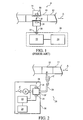
- FIG. 3 is a schematic diagram of another embodiment of a mainstream Gas Measurement System suitable for use with the present invention.
- FIG. 4 is a perspective view of the mainstream Gas Measurement System of FIG. 3 ;
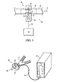
- FIG. 5 is a schematic diagram of a Gas Monitoring System according to the principles of the present invention.
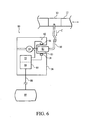
- FIG. 6 is schematic diagram of an exemplary embodiment of a sidestream Gas Measurement System that emulates the signal protocol of a mainstream Gas Measurement System.
- the present invention provides a convenient technique to interface a plurality of gas sensing technologies to a common Host System by means of a single interface unit. More specifically, one embodiment of the present invention contemplates providing an interface unit that is adapted to couple to any type of Gas Measurement System, i. e. , mainstream or sidestream. An output of the interface unit is coupled to a Host System. In this manner, the interface unit allows virtually any type of Gas Measurement System to communicate with a common Host System.
- FIG. 1 and 2 schematically illustrate two configurations of conventional Gas Measurement Systems that can be connected to such an interface unit.
- FIG. 3 schematically illustrates and FIG. 4 is a perspective view of another embodiment of a mainstream Gas Measurement System 60 adapted to be coupled to the interface unit.
- mainstream Gas Measurement System 60 includes a Sample Cell 10 disposed in breathing circuit 12 such that gas delivered to and/or received from the patient, as indicated by arrow A, passes through the Sample Cell.
- a Gas Sensor generally indicated at 50, is coupled to the Sample Cell.
- Gas Sensor 50 includes components, such as source 16 and detector 18, necessary to produce a detected signal 54 indicative of the concentration of a gas constituent in the gas sample in the Sample Cell.
- a Gas Monitor 22 is incorporated into the same housing 56 containing the Gas Sensor.
- Gas Monitor 22 includes processing elements that convert the detected signal from the Gas Sensor into a value, such as transmittance, that is used to produce an indication of the concentration of a particular gas constituent in the gas sample within the Sample Cell. This value indicative of the concentration of the gas under analysis is provided to a Host System 24 via a communication link 58.
- the Host System uses this information from Gas Monitor 22 in the same manner as a Host System associated with a conventional mainstream or sidestream Gas Measurement System.
- the mainstream Gas Measurement System is entirely contained within housing 56, which is selectively attachable to Sample Cell 10.
- a mainstream Gas Measurement System must be sufficiently small in size and lightweight as not to interfere with patient and/or ventilator management. With electronics manufacturing methods, as well as careful thermal and optical design, such a mainstream Gas Measurement System is possible.
- communication link 58 is a conventional electrical cable, a specialized cable, or a wireless link using any technologies known in the art, including but not limited to infrared and RF links.
- An exemplary application of the mainstream Gas Measurement System for carbon dioxide is monitoring an intubated patient receiving mechanical ventilation.
- Sample Cell 10 is placed between an endotracheal tube 62 inserted into the patient's trachea and the wye portion of breathing circuit 12 connected to a mechanical ventilator (not shown).
- the clinical indications for monitoring a patients carbon dioxide are well known in the art and have been reviewed in articles in general medical journals such as the New England Journal of Medicine as well as specific journals covering specialties such as anesthesiology, critical care, respiratory care, and emergency medicine.
- the stand-alone unit which is indicated by dashed line 26 in FIG. 1 , must include the processing elements of Gas Monitor 22, as well as the components of Host System 24.
- the stand-alone unit need only include the components of Host System 24. This enables the user to keep a low cost interface, i.e., Host System 24, that is suitable for use with a detachable Gas Measurement System.
- the user need not replace the Host System if upgrades to the Gas Sensor or Gas Monitor components are made.
- FIGS. 3 and 4 illustrate an exemplary embodiment of a mainstream Gas Measurement System
- the present invention contemplates providing a sidestream Gas Measurement System in a similar manner so that the Gas Sensing and Gas Monitoring components are provided in a housing separate from the housing containing the Host System components.
- An embodiment in which the sub-systems of the sidestream Gas Measurement System are contained within a common housing that is either selectively attached to the Sample Cell or integrated with the Sample Cell may interface to the same Host System 24 as the mainstream Gas Measurement System.
- the sampling means often a miniature pump, may be also contained within the housing of the Host System or the housing of the Gas Sensor and Gas Monitor.
- FIG. 5 is a schematic diagram of a Gas Monitoring System 63 according to the principles of the present invention, in which an interface unit 64 is provided that is adapted to couple to any type of Gas Measurement System, i.e., mainstream or sidestream, such as those illustrated in FIGS. 1-4 , to form the Gas Monitoring System.
- Interface unit 64 have an input coupling 66 and an output 68.
- Each Gas Measurement System 60, 8, and 28 has an output coupling 70a, 70b, and 70c that is adapted to be removably coupled to input coupling 66 of interface unit 64.
- a communication link 72a, 72b, and 72c, in the form of a hardwired connection is provided between each Gas Measurement System and input coupling 66 to connect each Gas Measurement System with the interface unit.
- interface unit 64 can include only one input coupling 66, so that only one Gas Measurement System can be connected to it at any given time.
- the present invention also contemplates providing more than one input couplings on the interface unit so that more than one Gas Measurement System can be coupled to the interface unit at a time.
- software in the interface unit, Host System 74, or Gas Measurement Systems should be provided to allow the system to determine or control which Gas Measurement System is presently communicating with the Host System.
- This communication control function can also be accomplished via hardware, such as with a switch provided on interface unit 64 to selectively activate one of the plurality of the input couplings.
- Interface unit 64 communicates with a Host System 74 via a communication link 72.
- Host system 74 provides the display and/or communication functionality to allow the output of the Gas Measurement System 60, 8, or 28 to be displayed, printed, downloaded, communicated, or otherwise transferred to a user.
- Communication link 72 is any conventional communication technique, such as hardwired or wireless.
- interface unit 64 effectively allows any type of Gas Measurement System, i.e., mainstream, sidestream, or a hybrid thereof, to communicate with a Host System so that a value indicative of the respiratory gas under analysis is provided to the Host System for analysis, display, or both.
- An advantage of this Gas Monitoring System is that any type of conventional Gas Measurement System can be coupled to interface unit 64, so that users need not purchase specialized gas monitoring systems.
- the respiratory gases to which the present invention applies include, but are not limited to, gases associated with respiration (i.e., oxygen and carbon dioxide), gases associated with anesthesia (i.e., nitrous oxide and halogenated agents), gases associated with therapy (i.e., helium/oxygen mixtures and nitric oxide) and gases or substances present in the breath known as markers of diseases or physiological processes (i.e., nitric oxide).
- gases associated with respiration i.e., oxygen and carbon dioxide
- gases associated with anesthesia i.e., nitrous oxide and halogenated agents
- gases associated with therapy i.e., helium/oxygen mixtures and nitric oxide
- gases or substances present in the breath known as markers of diseases or physiological processes
- the Gas Monitoring System of the present invention is capable of measuring the same gasses as a conventional sidestream or mainstream Gas Measurement System.
- the present invention also contemplates providing a sidestream Gas Measurement System capable of communicating with a Host System that is configured to interface solely with a mainstream Gas Measurement System. This is accomplished by providing a sidestream Gas Measurement System that is adapted to interface to a mainstream-only system by causing the sidestream Gas Measurement System to emulate the signals expected by a mainstream Gas Measurement System. In this manner, the sidestream Gas Measurement System can be used in conjunction with existing mainstream Gas Measurement Systems or with a Host System specifically configured for mainstream-only communication.
- FIG. 6 schematically illustrates a sidestream Gas Measurement System 80 that is adapted to emulate the signal protocol of a mainstream Gas Measurement System.
- Sidestream Gas Measurement System 80 includes a Sample Cell 81 in fluid communication with an airway of a patient via tube 30.
- Sample Cell 81 is selectively attachable to housing 36.
- a Sample Cell connector 83 in the form of a receptacle is provided in housing 36 to allow the Sample Cell to selectively attach to the housing such that the Sample Cell is in alignment with the components of a Gas Sensor 82 provided in the housing.
- An adapter 32 is connected in line in breathing circuit 12 to connect tube 30 to the breathing circuit.
- a nasal canula can be used as the gas collection element in place of adapter 32 so that the gas is taken directly at the patient's airway.
- the sample gas is continuously aspirated from the breathing circuit or the nasal canula through sampling tube 30, as indicated by arrow C, and into a Sample Cell 81.
- a pump 34 is typically provided to draw the gas into the Sample Cell from the gas sample site.
- sidestream Gas Measurement System 80 includes Gas Sensor 82 in communication with Sample Cell 81 when the Sample Cell is properly attached to the housing via the Sample Cell connector.
- Gas Sensor 82 outputs a signal indicative of a property of a gas in the Sample Cell. This signal is provided to a Gas Monitor 22, which processes the signal to determine a respiratory gas variable based on the signal.
- a processor 84 receives the respiratory gas variable and communicates it to a Host System 86 via a communication link 88.
- Communication link 88 is either hardwired or wireless, but is preferably configured to correspond to the communication link provided to a conventional mainstream Gas Measurement System so that an end of the communication link can plug into the coupling element of the conventional mainstream Gas Measurement System or a Host System specifically configured for mainstream-only communication.
- Processor 84 and Gas Monitor 22 may be configured into one processing system 85, as shown in FIG. 6 , or each function can be provided by separate processing elements.
- Processor 84 outputs the respiratory gas variable via communication link 88 in such a way so as to emulate the signal protocol that a mainstream Gas Measurement System uses to communicate with a Gas Sensor (i.e., the signal provided on cable 20 of FIG. 1 ) or to communicate with a Gas Sensor and Gas Monitor combination (i.e., the signal provided on communication link 58 of FIG. 3 ).
- a Gas Sensor i.e., the signal provided on cable 20 of FIG. 1
- a Gas Sensor and Gas Monitor combination i.e., the signal provided on communication link 58 of FIG. 3
- Emulation of the signal/control and power interfaces of a mainstream Gas Measurement System by the sidestream Gas Measurement System enables the sidestream Gas Measurement System to be used with a Host System designed to communicate only with a mainstream Gas Measurement System without the need to make any hardware modifications to the host portion of the respiratory gas monitoring system.
- the present invention therefore, allows the existing installed base of mainstream Gas Measurement Systems to integrate in a seamless fashion with the sidestream sampling capability without
- Mainstream Gas Measurement Systems typically require power to be provided to the Gas Sensor to heat the windows of the Sample Cell directly or indirectly to reduce condensation. Therefore, to emulate the power interface of the mainstream Gas Measurement System by a sidestream Gas Measurement System, it is required that the power supplied by the Gas Monitor or the Host System to the Gas Sensor for the intended purpose of heating the Sample Cell serve instead to provide power for the sidestream pump and the respective control electronics. Similarly, the control signals to regulate the signal to be interpreted as temperature must be provided by the sidestream Gas Measurement System to the Host System through the sensor interface.
- the sidestream Gas Measurement System In order for a continuous supply of power to be maintained to the pump and control electronics, the sidestream Gas Measurement System must provide a signal representative of a temperature that is high enough to prevent the Host System from generating an error condition in response to a temperature that appears to be below the operating range. At the same time, this signal must be below the nominal temperature intended for the mainstream Gas Measurement System or the Host System will reduce or cut off the power intended to heat the mainstream sensor thereby reducing or removing the power required to operate the pump and the respective control electronics.
- a fixed regulated voltage level, or a slow acting feedback circuit may be used.
- the feedback circuit must be filtered to react slowly in order to simulate the slow response of a heater in order to prevent the heater power from oscillating (or cycling up and down).
- Emulation of the signal/control interface of a mainstream Gas Measurement System requires a means to translate adverse conditions in the sidestream Gas Measurement System into conditions the Host System will recognize as interfering or error conditions so that the Host System can detect these and alert the user.
- the Gas Monitor or the Host System needs to detect and alert the user to conditions that may interfere with the ability of the Gas Measurement System to measure the respiratory gas.
- these conditions generally include the presence of liquids in the airway such as condensed water and other contaminants.
- these conditions include the presence of such liquids or contaminants in the sample tubing that is in fluid communication with the airway and the sidestream Gas Measurement System.
- the present invention provides the same feedback signals as generated by the mainstream Gas Measurement System to indicate when an interfering condition exists.
- a pressure sensor is provided to measure pressure drop near the Sample Cell of the sidestream Gas Measurement System
- a flow sensor consisting of a differential pressure sensor connected across a capillary tube is provided to measure the flow through the sampling tube are used by the control circuitry to detect the conditions that may interfere with the gas measurement. For example, an occlusion caused by the presence of contaminants in the sampling tube may be detected by a change in the flow as measured by the flow sensor. Also, a leak or disconnection of the sample tubing is detected by change in the pressure measurement in the Sample Cell by a pressure sensor.
- mainstream Gas Measurement Systems As these conditions do not occur in mainstream Gas Measurement Systems, the detection of either of these conditions are used to simulate a condition that does occur in mainstream Gas Measurement Systems, namely, contamination of the Sample Cell windows.
- contamination is detected optically by a reduction in the level of a reference optical signal, which is a measurement of transmitted light across the Sample Cell at a wavelength unaffected by the respiratory gas of interest.
- the present invention reduces the reference signal sent from the sidestream Gas Measurement System to the Host System whenever an interfering condition as described are detected.
- the sidestream Gas Measurement System can be connected directly to Host Systems designed to function only with a mainstream Gas Measurement System.
- Host Systems there may be certain calibration procedures that involve the use of an optical zero or reference cells, which are no longer needed with the use of sidestream Gas Measurement System.
- certain messages displayed by the Host System to alert the user to the presence of interfering conditions may be worded inappropriately for sidestream operation.
- a non-volatile memory device typically used in the mainstream Gas Measurement System to store calibration parameters and identification information is also used in the sidestream Gas Measurement System.
- the identifying information is encoded such that Host Systems would be able to determine the presence of a sidestream Gas Measurement System if the software in the Host System was so enabled it could remove access to non-applicable calibration procedures and can alter the wording of messages as appropriate.
- sidestream Gas Measurement System 80 can also be used in the configuration shown in FIG. 5 . That is, the present invention contemplates that sidestream Gas Measurement System 80 can provide an output to an interface unit that is, in turn, connected to a Host System.
- Similar emulation methods can also be employed to enable a mainstream Gas Measurement System to be connected to Host Systems designed to function only with a sidestream Gas Measurement System. This is accomplished, for example, by interposing the roles of the various mainstream and sidestream interface requirements and by providing a self contained temperature control system for heating of the Sample Cell windows within the mainstream Gas Measurement System.
- Sample Cell - A device configured to contain a static or dynamic gas sample and in which the concentration of a particular gas constituent in the gas sample is ascertained.
- Gas Sensor - Gas constituent measuring components associated with a Sample Cell such as an optical emitter and detector, that produce a detected signal indicative of the concentration of a gas constituent in the gas sample under evaluation.
- This detected signal is typically processed to produce an indication of the concentration of a particular gas constituent in the gas sample within the Sample Cell.
- Gas Monitor - Device that contains the functionality, such as the processing elements, required to produce an indication of the concentration of a particular gas constituent in the gas sample within the Sample Cell based on the detected signal form the Gas Sensor.
- Gas Measurement System - System that includes a Sample Cell, Gas Sensor, and Gas Monitor. It is to be understood that these components can be physically separated or separable from on another, or various combinations of components can be located in one unit.
- the Gas Sensor and Gas Monitor are provided in a common housing with the Sample Cell being selectively attachable to the housing.
- Host System A system that receives from an output from a Gas Measurement System an indication of the gas constituent under evaluation.
- the present invention contemplates that the Host System uses this information in any one of a variety ways.
- the Host System may display the indication of the designated gas as a waveform or as a value in partial pressure units, such as mmHg or concentration in units such as a percent (%).
- the Host System can use the indication to calculate other parameters, which can then be displayed or communicated to another system, such as a central station or an interface unit.
- Gas Monitoring System - System that includes the Host System and the Gas Measurement System (Sample Cell, Gas Sensor, and Gas Monitor).
Landscapes
- Health & Medical Sciences (AREA)
- Life Sciences & Earth Sciences (AREA)
- Physics & Mathematics (AREA)
- General Health & Medical Sciences (AREA)
- Pathology (AREA)
- Veterinary Medicine (AREA)
- Animal Behavior & Ethology (AREA)
- Public Health (AREA)
- Molecular Biology (AREA)
- Surgery (AREA)
- Spectroscopy & Molecular Physics (AREA)
- Physiology (AREA)
- Pulmonology (AREA)
- Biophysics (AREA)
- Engineering & Computer Science (AREA)
- Biomedical Technology (AREA)
- Heart & Thoracic Surgery (AREA)
- Medical Informatics (AREA)
- General Physics & Mathematics (AREA)
- Immunology (AREA)
- Biochemistry (AREA)
- Analytical Chemistry (AREA)
- Chemical & Material Sciences (AREA)
- Emergency Medicine (AREA)
- Obesity (AREA)
- Measurement Of The Respiration, Hearing Ability, Form, And Blood Characteristics Of Living Organisms (AREA)
- Sampling And Sample Adjustment (AREA)
- Investigating Or Analysing Materials By Optical Means (AREA)
- Measuring Volume Flow (AREA)
- Arrangements For Transmission Of Measured Signals (AREA)
- Investigating Or Analyzing Materials By The Use Of Electric Means (AREA)
- Emergency Alarm Devices (AREA)
Claims (9)
- Système de surveillance de gaz respiratoire comprenant :une unité d'interface (64) ayant un couplage d'entrée (66) et une sortie (68) ; etune pluralité de systèmes de mesure de gaz (8, 28, 60), ayant chacun un logement séparé, dans lequel chaque système de mesure de gaz est conçu pour être placé en communication fluidique avec une voie respiratoire d'un patient pour mesurer au moins un gaz respiratoire, dans lequel chaque système de mesure de gaz a un couplage de sortie (70a, 70b, 70c) qui est conçu pour être couplé de manière amovible au couplage d'entrée de l'unité d'interface, et dans lequel chaque système de mesure de gaz comprend un moyen de traitement (22) permettant de déterminer, à partir du gaz respiratoire, au moins une variable respiratoire d'un tel patient et permettant de fournir une sortie à l'unité d'interface par le biais du couplage de sortie.
- Système de surveillance de gaz respiratoire selon la revendication 1, dans lequel la pluralité de systèmes de mesure de gaz comprend un système de mesure de courant gazeux latéral et un système de mesure de courant gazeux principal.
- Système de surveillance de gaz respiratoire selon la revendication 1, dans lequel la sortie de l'unité d'interface est un lien de communication filaire (72) ou un lien de communication sans fil.
- Système de surveillance de gaz respiratoire selon la revendication 1, comprenant en outre un écran couplé à la sortie de l'unité d'interface, dans lequel l'écran est conçu pour afficher la variable respiratoire d'un tel patient fournie par n'importe lequel de la pluralité de systèmes de mesure de gaz.
- Système de surveillance de gaz respiratoire selon la revendication 1, dans lequel la pluralité de systèmes de mesure de gaz comprend un système de mesure de courant gazeux latéral (80) conçu pour communiquer avec un système hôte (86) qui est configuré pour communiquer uniquement avec un système de mesure de courant gazeux principal, le système de mesure de courant gazeux latéral comprenant :un logement (36) ; etun connecteur de cellule échantillon (83) associé au logement et conçu pour recevoir une cellule échantillon ;un détecteur de gaz (82) agencé dans le logement par rapport au connecteur de cellule échantillon de sorte à être en communication avec la cellule échantillon réagissant à la cellule échantillon reçue dans le connecteur de cellule échantillon, et dans lequel le détecteur de gaz émet un signal indiquant une propriété d'un gaz dans la cellule échantillon ;un moyen d'imitation (84) recevant ce signal du détecteur de gaz et utilisant le signal dans un signal de sortie pour simuler des signaux de sortie par un système de mesure de courant gazeux principal ; etun élément de communication (88) couplé de manière fonctionnelle au moyen d'imitation pour mettre en contact le système de mesure de courant gazeux latéral avec un tel système hôte.
- Système de surveillance de gaz respiratoire selon la revendication 1, dans lequel la pluralité de systèmes de mesure de gaz comprend un système de mesure de courant gazeux latéral (80), comprenant :un premier conduit (30) ayant une première extrémité conçue pour être placée en communication fluidique avec un circuit patient (12) et une deuxième extrémité,une cellule échantillon (81) agencée à la deuxième extrémité du premier conduit ;un détecteur de gaz (82) couplé de manière fonctionnelle à la cellule échantillon, dans lequel le détecteur de gaz émet un signal indiquant une propriété d'un gaz ;un élément de traitement (24) conçu pour recevoir le signal et déterminer une variable de gaz respiratoire basée sur le signal ; etune interface de système hôte (88) configurée pour mettre en communication une sortie de l'élément de traitement avec un système hôte configuré pour être uniquement en contact avec un système de mesure de courant gazeux principal, et dans lequel l'élément de traitement configure les signaux fournis par l'interface de système hôte pour imiter les signaux fournis par un système de mesure de courant gazeux principal ou une partie de celui-ci.
- Procédé de surveillance de gaz respiratoire comprenant les étapes consistant à :fournir une unité d'interface (64) ayant un couplage d'entrée (66) et une sortie (68) ;fournir une pluralité de systèmes de mesure de gaz (8, 28, 60), ayant chacun un logement séparé, dans lequel chaque système de mesure de gaz a un couplage de sortie (70a, 70b, 70c), et dans lequel chaque système de mesure de gaz comprend un moyen de traitement (22) permettant de déterminer, à partir du gaz respiratoire, au moins une variable respiratoire d'un tel patient et permettant de fournir une sortie à une unité d'interface par le biais du couplage de sortie ; etcoupler de manière sélective un de la pluralité de systèmes de mesure de gaz à l'unité d'interface en couplant le couplage de sortie à un système de mesure de gaz associé avec le couplage d'entrée de l'unité d'interface.
- Procédé selon la revendication 7, comprenant en outre :le couplage fonctionnel de la sortie du dispositif d'interface à un système hôte (74) ; etla communication de la variable de gaz respiratoire au moins au nombre de une du système de mesure de gaz au système hôte par le biais de l'unité d'interface.
- Procédé de surveillance de gaz selon la revendication 7, dans lequel ladite fourniture d'une pluralité de systèmes de mesure de gaz comprend les étapes consistant à :relier un premier conduit (30) à une voie respiratoire d'un patient ;communiquer un flux de gaz à travers le premier conduit à une cellule échantillon (81) ;mesurer une propriété de gaz dans la cellule échantillon par le biais d'un détecteur de gaz couplé de manière fonctionnelle à la cellule échantillon ;imiter les signaux fournis par un système de mesure de courant gazeux principal ou une partie de celui-ci, y compris la propriété mesurée ; etfournir les signaux à un système hôte configuré pour être uniquement en contact avec un système de mesure de courant gazeux principal.
Priority Applications (1)
| Application Number | Priority Date | Filing Date | Title |
|---|---|---|---|
| EP09167553A EP2116848B1 (fr) | 2003-02-21 | 2004-02-19 | Systeme de surveillance de gaz et systeme de mesure de courant gazeux lateral connu pour communiquer avec un systeme de mesure de courant gazeux principal |
Applications Claiming Priority (3)
| Application Number | Priority Date | Filing Date | Title |
|---|---|---|---|
| US44942803P | 2003-02-21 | 2003-02-21 | |
| US10/781,382 US6954702B2 (en) | 2003-02-21 | 2004-02-18 | Gas monitoring system and sidestream gas measurement system adapted to communicate with a mainstream gas measurement system |
| PCT/US2004/005178 WO2004076944A2 (fr) | 2003-02-21 | 2004-02-19 | Systeme de surveillance de gaz et systeme de mesure de courant gazeux lateral conçu pour communiquer avec un systeme de mesure de courant gazeux principal |
Related Child Applications (2)
| Application Number | Title | Priority Date | Filing Date |
|---|---|---|---|
| EP09167553A Division EP2116848B1 (fr) | 2003-02-21 | 2004-02-19 | Systeme de surveillance de gaz et systeme de mesure de courant gazeux lateral connu pour communiquer avec un systeme de mesure de courant gazeux principal |
| EP09167553.8 Division-Into | 2009-08-10 |
Publications (3)
| Publication Number | Publication Date |
|---|---|
| EP1620683A2 EP1620683A2 (fr) | 2006-02-01 |
| EP1620683A4 EP1620683A4 (fr) | 2007-06-13 |
| EP1620683B1 true EP1620683B1 (fr) | 2010-05-05 |
Family
ID=32930511
Family Applications (2)
| Application Number | Title | Priority Date | Filing Date |
|---|---|---|---|
| EP04712927A Expired - Lifetime EP1620683B1 (fr) | 2003-02-21 | 2004-02-19 | Systeme de surveillance de gaz et systeme de mesure de courant gazeux lateral conçu pour communiquer avec un systeme de mesure de courant gazeux principal |
| EP09167553A Expired - Lifetime EP2116848B1 (fr) | 2003-02-21 | 2004-02-19 | Systeme de surveillance de gaz et systeme de mesure de courant gazeux lateral connu pour communiquer avec un systeme de mesure de courant gazeux principal |
Family Applications After (1)
| Application Number | Title | Priority Date | Filing Date |
|---|---|---|---|
| EP09167553A Expired - Lifetime EP2116848B1 (fr) | 2003-02-21 | 2004-02-19 | Systeme de surveillance de gaz et systeme de mesure de courant gazeux lateral connu pour communiquer avec un systeme de mesure de courant gazeux principal |
Country Status (10)
| Country | Link |
|---|---|
| US (5) | US6954702B2 (fr) |
| EP (2) | EP1620683B1 (fr) |
| JP (1) | JP4613159B2 (fr) |
| CN (1) | CN1839311B (fr) |
| AT (1) | ATE467121T1 (fr) |
| AU (1) | AU2004214962B2 (fr) |
| BR (1) | BRPI0407739A (fr) |
| CA (1) | CA2516570C (fr) |
| DE (1) | DE602004027023D1 (fr) |
| WO (1) | WO2004076944A2 (fr) |
Families Citing this family (82)
| Publication number | Priority date | Publication date | Assignee | Title |
|---|---|---|---|---|
| US20100036272A1 (en) * | 1996-07-15 | 2010-02-11 | Koninklijke Philips Electronics N.V. | Metabolic measure system including a multiple function airway adapter |
| US5915379A (en) | 1997-03-14 | 1999-06-29 | Nellcor Puritan Bennett Incorporated | Graphic user interface for a patient ventilator |
| SE0203427D0 (sv) * | 2002-11-20 | 2002-11-20 | Siemens Elema Ab | Anordning för passiv gassampling |
| US10478115B2 (en) * | 2004-10-04 | 2019-11-19 | Spirofriend Technology Aps | Handheld home monitoring sensors network device |
| GB2421442B (en) * | 2004-11-22 | 2008-04-16 | Mark Varney | Tidal gas resuscitation monitor |
| US20060178592A1 (en) * | 2005-02-07 | 2006-08-10 | Aperson Biosystems Corp. | System and method for controlling the flow of exhaled breath during analysis |
| US8021310B2 (en) | 2006-04-21 | 2011-09-20 | Nellcor Puritan Bennett Llc | Work of breathing display for a ventilation system |
| US7748280B2 (en) * | 2006-07-06 | 2010-07-06 | Ric Investments, Llc | Sidestream gas sampling system with closed sample circuit |
| US7784461B2 (en) | 2006-09-26 | 2010-08-31 | Nellcor Puritan Bennett Llc | Three-dimensional waveform display for a breathing assistance system |
| US8021615B2 (en) * | 2006-10-06 | 2011-09-20 | Ric Investments, Llc | Sensor that compensates for deterioration of a luminescable medium |
| US20080119753A1 (en) * | 2006-11-16 | 2008-05-22 | Cardiopulmonary Technologies, Inc. | Premature infant side-stream respiratory gas monitoring sensor |
| US8312878B2 (en) | 2006-12-04 | 2012-11-20 | Ric Investments, Llc | Compensation of volumetric errors in a gas monitoring system |
| CN101210931B (zh) * | 2006-12-27 | 2011-12-21 | 中国科学院沈阳自动化研究所 | 一种总线式可燃气体浓度检测装置及其控制方法 |
| KR100874111B1 (ko) * | 2007-03-05 | 2008-12-15 | 한국과학기술원 | 호흡분석과 동맥혈 측정을 통한 비침습적 호흡특성치예측방법 및 표시장치 |
| US20080221930A1 (en) | 2007-03-09 | 2008-09-11 | Spacelabs Medical, Inc. | Health data collection tool |
| US10918308B2 (en) * | 2007-05-18 | 2021-02-16 | Koninklijke Philips N.V. | Respiratory component measurement system including a sensor for detecting orientation or motion |
| US8146403B2 (en) * | 2007-09-17 | 2012-04-03 | Life Safety Distribution Ag | Gas sensor with smart pellistor |
| EP2062531A1 (fr) * | 2007-11-26 | 2009-05-27 | GE Healthcare Finland Oy | Détecteur de voie respiratoire de function multiple |
| US9521963B2 (en) * | 2008-05-13 | 2016-12-20 | Ric Investments, Llc | Respiratory component measurement system with indicating elements |
| JP5067698B2 (ja) * | 2008-06-03 | 2012-11-07 | 日本光電工業株式会社 | フロー計測システム並びに生体情報モニタ |
| DE102008027630A1 (de) * | 2008-06-05 | 2009-12-10 | Filt Lungen- Und Thoraxdiagnostik Gmbh | Transportabler Pneumotachograph zur Messung von Bestandteilen des Exspirationsvolumens |
| US20100051026A1 (en) * | 2008-09-04 | 2010-03-04 | Nellcor Puritan Bennett Llc | Ventilator With Controlled Purge Function |
| US8181648B2 (en) | 2008-09-26 | 2012-05-22 | Nellcor Puritan Bennett Llc | Systems and methods for managing pressure in a breathing assistance system |
| US8113062B2 (en) | 2008-09-30 | 2012-02-14 | Nellcor Puritan Bennett Llc | Tilt sensor for use with proximal flow sensing device |
| US8302602B2 (en) | 2008-09-30 | 2012-11-06 | Nellcor Puritan Bennett Llc | Breathing assistance system with multiple pressure sensors |
| US20120118291A1 (en) * | 2009-04-27 | 2012-05-17 | Ian Brodkin | Apparatus and method for monitoring the degree of integration between the functions of the heart and the lungs, and the therapeutic success of resuscitative interventions |
| US8776790B2 (en) | 2009-07-16 | 2014-07-15 | Covidien Lp | Wireless, gas flow-powered sensor system for a breathing assistance system |
| DE102009038238A1 (de) * | 2009-08-20 | 2011-02-24 | Siemens Aktiengesellschaft | Sensor-Plattform für die Atemgasanalyse |
| US9604020B2 (en) | 2009-10-16 | 2017-03-28 | Spacelabs Healthcare Llc | Integrated, extendable anesthesia system |
| EP2488837A4 (fr) | 2009-10-16 | 2017-11-15 | Spacelabs Healthcare LLC | Tube d'écoulement amélioré par un éclairage |
| US8469030B2 (en) | 2009-12-01 | 2013-06-25 | Covidien Lp | Exhalation valve assembly with selectable contagious/non-contagious latch |
| US8439037B2 (en) | 2009-12-01 | 2013-05-14 | Covidien Lp | Exhalation valve assembly with integrated filter and flow sensor |
| US8439036B2 (en) | 2009-12-01 | 2013-05-14 | Covidien Lp | Exhalation valve assembly with integral flow sensor |
| US20110126832A1 (en) * | 2009-12-01 | 2011-06-02 | Nellcor Puritan Bennett Llc | Exhalation Valve Assembly |
| US8469031B2 (en) | 2009-12-01 | 2013-06-25 | Covidien Lp | Exhalation valve assembly with integrated filter |
| US9119925B2 (en) | 2009-12-04 | 2015-09-01 | Covidien Lp | Quick initiation of respiratory support via a ventilator user interface |
| US8924878B2 (en) | 2009-12-04 | 2014-12-30 | Covidien Lp | Display and access to settings on a ventilator graphical user interface |
| US8335992B2 (en) | 2009-12-04 | 2012-12-18 | Nellcor Puritan Bennett Llc | Visual indication of settings changes on a ventilator graphical user interface |
| US9262588B2 (en) | 2009-12-18 | 2016-02-16 | Covidien Lp | Display of respiratory data graphs on a ventilator graphical user interface |
| US8499252B2 (en) | 2009-12-18 | 2013-07-30 | Covidien Lp | Display of respiratory data graphs on a ventilator graphical user interface |
| CN102905616B (zh) | 2010-03-21 | 2017-02-08 | 太空实验室健康护理有限公司 | 多显示器床旁监护系统 |
| USD655405S1 (en) | 2010-04-27 | 2012-03-06 | Nellcor Puritan Bennett Llc | Filter and valve body for an exhalation module |
| USD655809S1 (en) | 2010-04-27 | 2012-03-13 | Nellcor Puritan Bennett Llc | Valve body with integral flow meter for an exhalation module |
| USD653749S1 (en) | 2010-04-27 | 2012-02-07 | Nellcor Puritan Bennett Llc | Exhalation module filter body |
| US11628267B2 (en) | 2010-08-04 | 2023-04-18 | Medline Industries, Lp | Universal medical gas delivery system |
| US8707950B1 (en) * | 2010-08-04 | 2014-04-29 | Darren Rubin | Universal medical gas delivery system |
| US9047747B2 (en) | 2010-11-19 | 2015-06-02 | Spacelabs Healthcare Llc | Dual serial bus interface |
| US8783250B2 (en) | 2011-02-27 | 2014-07-22 | Covidien Lp | Methods and systems for transitory ventilation support |
| US9629566B2 (en) | 2011-03-11 | 2017-04-25 | Spacelabs Healthcare Llc | Methods and systems to determine multi-parameter managed alarm hierarchy during patient monitoring |
| EP2701593B1 (fr) * | 2011-04-26 | 2015-06-17 | Koninklijke Philips N.V. | Analyseur de gaz principal configurable pour couplage de façon amovible avec un composant d'échantillonnage de gaz latéral |
| US9629971B2 (en) | 2011-04-29 | 2017-04-25 | Covidien Lp | Methods and systems for exhalation control and trajectory optimization |
| CN103957775A (zh) * | 2011-12-01 | 2014-07-30 | 皇家飞利浦有限公司 | 用于使用具有紧密集成的控制电子器件的泵和检测器来监测侧流系统中的成分的系统和方法 |
| GB2514973B (en) | 2012-04-05 | 2018-12-19 | Fisher & Paykel Healthcare Ltd | Respiratory assistance apparatus |
| US9993604B2 (en) | 2012-04-27 | 2018-06-12 | Covidien Lp | Methods and systems for an optimized proportional assist ventilation |
| US10362967B2 (en) | 2012-07-09 | 2019-07-30 | Covidien Lp | Systems and methods for missed breath detection and indication |
| EP2914321B1 (fr) * | 2012-10-31 | 2019-02-27 | Maquet Critical Care AB | Appareil respiratoire et procédé associé |
| US9375542B2 (en) | 2012-11-08 | 2016-06-28 | Covidien Lp | Systems and methods for monitoring, managing, and/or preventing fatigue during ventilation |
| BR102012032974A8 (pt) * | 2012-12-21 | 2018-05-22 | Whirlpool Sa | sistema de mensuração de fluxo de gás para aparelhos eletrodomésticos |
| US9358355B2 (en) | 2013-03-11 | 2016-06-07 | Covidien Lp | Methods and systems for managing a patient move |
| US9950135B2 (en) | 2013-03-15 | 2018-04-24 | Covidien Lp | Maintaining an exhalation valve sensor assembly |
| US10987026B2 (en) | 2013-05-30 | 2021-04-27 | Spacelabs Healthcare Llc | Capnography module with automatic switching between mainstream and sidestream monitoring |
| WO2015057924A1 (fr) * | 2013-10-17 | 2015-04-23 | Mustang Sampling Llc | Système d'analyse d'échantillon alimenté par le soleil utilisant une instrumentation analytique déployé en champ et un tubage de petit diamètre chemisé sous vide |
| WO2015183107A1 (fr) | 2014-05-27 | 2015-12-03 | Fisher & Paykel Healthcare Limited | Mélange et mesure de gaz pour un dispositif médical |
| US9950129B2 (en) | 2014-10-27 | 2018-04-24 | Covidien Lp | Ventilation triggering using change-point detection |
| EP3020437B1 (fr) * | 2014-11-13 | 2023-06-07 | Shenzhen Mindray Bio-Medical Electronics Co., Ltd. | Contrôle d'un flux dans un système pneumatique |
| JP6574484B2 (ja) * | 2014-12-30 | 2019-09-11 | コーニンクレッカ フィリップス エヌ ヴェKoninklijke Philips N.V. | 補助酸素の検出を伴うカプノメトリシステム及びその動作方法 |
| AU2016364628B2 (en) | 2015-12-02 | 2022-06-23 | Fisher & Paykel Healthcare Limited | Flow path sensing for flow therapy apparatus |
| USD828857S1 (en) * | 2016-09-07 | 2018-09-18 | Mustang Sampling, Llc | Probe mounting adapter |
| US11209417B2 (en) | 2017-10-12 | 2021-12-28 | Carrot, Inc. | Breath sensor apparatus and methods of use |
| AU2018353928B2 (en) | 2017-11-14 | 2019-06-13 | Covidien Lp | Methods and systems for drive pressure spontaneous ventilation |
| DE102017011625A1 (de) | 2017-12-15 | 2019-07-18 | Drägerwerk AG & Co. KGaA | Verfahren, Computerprogramm, Vorrichtung und Beatmungssystem zur Detektion eines Lecks in einem Patientengasmodul |
| CN109991043B (zh) * | 2017-12-31 | 2022-07-05 | 中国人民解放军63653部队 | 基于高温管式气氛炉的差压式取气测量系统 |
| JP7118684B2 (ja) * | 2018-03-27 | 2022-08-16 | 日本光電工業株式会社 | 呼吸気情報検出センサ、呼吸気情報検出装置 |
| US11517691B2 (en) | 2018-09-07 | 2022-12-06 | Covidien Lp | Methods and systems for high pressure controlled ventilation |
| US11366056B2 (en) | 2019-10-01 | 2022-06-21 | GE Precision Healthcare LLC | Respiratory gas analyzer and a beam splitter therefor |
| EP4076178A4 (fr) * | 2019-12-17 | 2024-01-10 | Cedars Sinai Medical Center | Analyse de gaz respiratoires |
| EP4084685A4 (fr) * | 2019-12-31 | 2024-01-10 | Mcneil Ab | Procédés et appareil de mesure de capteur d'haleine |
| CA3166435A1 (fr) | 2019-12-31 | 2021-07-08 | Mcneil Ab | Procedes et appareil d'etalonnage de capteur d'haleine |
| DE102020002570A1 (de) | 2020-04-29 | 2021-11-04 | Drägerwerk AG & Co. KGaA | Verfahren und Vorrichtung zur Detektion eines Lecks in einem Beatmungskreislauf |
| US11672934B2 (en) | 2020-05-12 | 2023-06-13 | Covidien Lp | Remote ventilator adjustment |
| DE102021111431A1 (de) | 2020-06-29 | 2021-12-30 | Dräger Safety AG & Co. KGaA | Überwachungssystem |
| DE102022110302A1 (de) | 2022-04-28 | 2023-11-02 | Drägerwerk AG & Co. KGaA | Gasmessvorrichtung zur Konzentrationsbestimmung mindestens einer Gaskomponente in einem Atemgasgemisch |
Family Cites Families (28)
| Publication number | Priority date | Publication date | Assignee | Title |
|---|---|---|---|---|
| US4177381A (en) * | 1974-09-27 | 1979-12-04 | Andros Incorporated | Gas analyzer sample cell |
| US4692621A (en) * | 1985-10-11 | 1987-09-08 | Andros Anlayzers Incorporated | Digital anesthetic agent analyzer |
| US4907166A (en) * | 1986-10-17 | 1990-03-06 | Nellcor, Inc. | Multichannel gas analyzer and method of use |
| US4914720A (en) * | 1986-12-04 | 1990-04-03 | Cascadia Technology Corporation | Gas analyzers |
| US4958075A (en) * | 1987-10-09 | 1990-09-18 | Ntc Technology Inc. | Gas analyzer |
| FI82367C (fi) * | 1988-02-11 | 1991-03-11 | Instrumentarium Oy | Till intubationsroer kopplad spirometer och provtagningsfoerbindning i gasanalysator. |
| DE69024613T2 (de) * | 1989-10-27 | 1996-08-01 | Alcatel Italia | Einrichtung zur Erzeugung von Schaltkriterien und zur adaptiven Entzerrung von Datensprektren |
| US5252473A (en) * | 1990-01-23 | 1993-10-12 | Battelle Memorial Institute | Production of esters of lactic acid, esters of acrylic acid, lactic acid, and acrylic acid |
| US5363857A (en) * | 1990-05-22 | 1994-11-15 | Aerosport, Inc. | Metabolic analyzer |
| US5282473A (en) | 1992-11-10 | 1994-02-01 | Critikon, Inc. | Sidestream infrared gas analyzer requiring small sample volumes |
| US5464982A (en) * | 1994-03-21 | 1995-11-07 | Andros Incorporated | Respiratory gas analyzer |
| JPH09192118A (ja) * | 1996-01-18 | 1997-07-29 | Aisan Ind Co Ltd | 酸素消費量測定装置 |
| US6325978B1 (en) * | 1998-08-04 | 2001-12-04 | Ntc Technology Inc. | Oxygen monitoring and apparatus |
| CN1249036A (zh) * | 1997-03-11 | 2000-03-29 | 菲舍尔分析仪器有限公司 | 碳同位素分析仪 |
| US6309360B1 (en) * | 1997-03-17 | 2001-10-30 | James R. Mault | Respiratory calorimeter |
| US5925831A (en) * | 1997-10-18 | 1999-07-20 | Cardiopulmonary Technologies, Inc. | Respiratory air flow sensor |
| EP1156846A1 (fr) * | 1999-02-03 | 2001-11-28 | University Of Florida | Methode et appareil permettant d'annuler un travail ventilatoire impose |
| GB2347999B (en) * | 1999-03-17 | 2001-11-28 | Cambustion Ltd | Oxides of carbon detector |
| AU2001243541B8 (en) * | 2000-03-13 | 2004-05-27 | Natus Medical, Inc. | Method and apparatus for in-vivo measurement of carbon monoxide production rate |
| DE10031079A1 (de) * | 2000-06-30 | 2002-02-07 | Map Gmbh | Vorrichtung zur Erfassung der Atmungsstätigkeit einer Person sowie Vorrichtung zur Vorgabe physikalischer Parameter bei der Zufuhr eines Atemgases |
| US6632402B2 (en) * | 2001-01-24 | 2003-10-14 | Ntc Technology Inc. | Oxygen monitoring apparatus |
| JP2002306436A (ja) * | 2001-04-16 | 2002-10-22 | Fukuda M Ii Kogyo Kk | 動物の生体情報監視装置 |
| SE0103182D0 (sv) * | 2001-09-25 | 2001-09-25 | Siemens Elema Ab | Förfarande för lungmekanisk undersökning och andningsapparatsystem |
| SE524086C2 (sv) * | 2001-10-30 | 2004-06-22 | Phase In Ab | Mäthuvud för gasanalysator |
| US7341563B2 (en) * | 2002-04-04 | 2008-03-11 | Ric Investments, Llc | Sidestream gas sampling system with detachable sample cell |
| US7478634B2 (en) * | 2002-09-17 | 2009-01-20 | Jam Mohammad R | Respiratory booster machine and method for enhancing ventilation |
| US7183552B2 (en) * | 2003-03-07 | 2007-02-27 | Ric Investments, Llc | Optical system for a gas measurement system |
| US6828910B2 (en) * | 2003-04-16 | 2004-12-07 | Ge Medical Systems Information Technologies, Inc. | Apparatus for monitoring gas concentrations |
-
2004
- 2004-02-18 US US10/781,382 patent/US6954702B2/en not_active Expired - Fee Related
- 2004-02-19 AU AU2004214962A patent/AU2004214962B2/en not_active Ceased
- 2004-02-19 CA CA2516570A patent/CA2516570C/fr not_active Expired - Fee Related
- 2004-02-19 AT AT04712927T patent/ATE467121T1/de not_active IP Right Cessation
- 2004-02-19 BR BRPI0407739-3A patent/BRPI0407739A/pt not_active Application Discontinuation
- 2004-02-19 EP EP04712927A patent/EP1620683B1/fr not_active Expired - Lifetime
- 2004-02-19 WO PCT/US2004/005178 patent/WO2004076944A2/fr active Application Filing
- 2004-02-19 DE DE602004027023T patent/DE602004027023D1/de not_active Expired - Lifetime
- 2004-02-19 EP EP09167553A patent/EP2116848B1/fr not_active Expired - Lifetime
- 2004-02-19 CN CN200480007569.5A patent/CN1839311B/zh not_active Expired - Fee Related
- 2004-02-19 JP JP2006503771A patent/JP4613159B2/ja not_active Expired - Fee Related
-
2005
- 2005-10-04 US US11/243,001 patent/US7684931B2/en not_active Expired - Fee Related
-
2007
- 2007-10-31 US US11/931,858 patent/US20080058667A1/en not_active Abandoned
- 2007-10-31 US US11/932,119 patent/US7606668B2/en not_active Expired - Fee Related
-
2010
- 2010-02-02 US US12/698,431 patent/US20100137729A1/en not_active Abandoned
Also Published As
| Publication number | Publication date |
|---|---|
| US6954702B2 (en) | 2005-10-11 |
| EP1620683A4 (fr) | 2007-06-13 |
| CN1839311A (zh) | 2006-09-27 |
| AU2004214962A1 (en) | 2004-09-10 |
| US20080058667A1 (en) | 2008-03-06 |
| WO2004076944A3 (fr) | 2006-03-23 |
| AU2004214962B2 (en) | 2009-09-10 |
| US20060052950A1 (en) | 2006-03-09 |
| JP2006519638A (ja) | 2006-08-31 |
| US20100137729A1 (en) | 2010-06-03 |
| US20080114223A1 (en) | 2008-05-15 |
| CN1839311B (zh) | 2011-11-23 |
| DE602004027023D1 (de) | 2010-06-17 |
| BRPI0407739A (pt) | 2006-02-14 |
| EP2116848B1 (fr) | 2013-01-16 |
| US7606668B2 (en) | 2009-10-20 |
| US20040186391A1 (en) | 2004-09-23 |
| EP1620683A2 (fr) | 2006-02-01 |
| WO2004076944A2 (fr) | 2004-09-10 |
| CA2516570C (fr) | 2012-05-08 |
| JP4613159B2 (ja) | 2011-01-12 |
| ATE467121T1 (de) | 2010-05-15 |
| US7684931B2 (en) | 2010-03-23 |
| EP2116848A1 (fr) | 2009-11-11 |
| CA2516570A1 (fr) | 2004-09-10 |
Similar Documents
| Publication | Publication Date | Title |
|---|---|---|
| EP1620683B1 (fr) | Systeme de surveillance de gaz et systeme de mesure de courant gazeux lateral conçu pour communiquer avec un systeme de mesure de courant gazeux principal | |
| US6828910B2 (en) | Apparatus for monitoring gas concentrations | |
| US6629934B2 (en) | Indirect calorimeter for medical applications | |
| EP1490666B1 (fr) | Systeme d'echantillonnage de gaz a deviation dote d'une cellule d'echantillon detachable | |
| KR101699000B1 (ko) | 호흡 분석 | |
| US5676132A (en) | Pulmonary interface system | |
| US10441195B2 (en) | System, method and device for aiding in the diagnosis of respiratory dysfunction | |
| EP1440305A1 (fr) | Tete de mesure pour analyseur de gaz | |
| AU761894B2 (en) | Pulmonary interface system | |
| AU1086097A (en) | Pulmonary interface system |
Legal Events
| Date | Code | Title | Description |
|---|---|---|---|
| PUAI | Public reference made under article 153(3) epc to a published international application that has entered the european phase |
Free format text: ORIGINAL CODE: 0009012 |
|
| 17P | Request for examination filed |
Effective date: 20050914 |
|
| AK | Designated contracting states |
Kind code of ref document: A2 Designated state(s): AT BE BG CH CY CZ DE DK EE ES FI FR GB GR HU IE IT LI LU MC NL PT RO SE SI SK TR |
|
| AX | Request for extension of the european patent |
Extension state: AL LT LV MK |
|
| PUAK | Availability of information related to the publication of the international search report |
Free format text: ORIGINAL CODE: 0009015 |
|
| DAX | Request for extension of the european patent (deleted) | ||
| RIC1 | Information provided on ipc code assigned before grant |
Ipc: G01N 33/00 20060101AFI20060419BHEP |
|
| A4 | Supplementary search report drawn up and despatched |
Effective date: 20070511 |
|
| RIN1 | Information on inventor provided before grant (corrected) |
Inventor name: RICH, DAVID, R. Inventor name: PIERRY, ANTHONY, T. |
|
| 17Q | First examination report despatched |
Effective date: 20080821 |
|
| RAP1 | Party data changed (applicant data changed or rights of an application transferred) |
Owner name: RIC INVESTMENTS, LLC. |
|
| GRAP | Despatch of communication of intention to grant a patent |
Free format text: ORIGINAL CODE: EPIDOSNIGR1 |
|
| GRAS | Grant fee paid |
Free format text: ORIGINAL CODE: EPIDOSNIGR3 |
|
| GRAA | (expected) grant |
Free format text: ORIGINAL CODE: 0009210 |
|
| AK | Designated contracting states |
Kind code of ref document: B1 Designated state(s): AT BE BG CH CY CZ DE DK EE ES FI FR GB GR HU IE IT LI LU MC NL PT RO SE SI SK TR |
|
| REG | Reference to a national code |
Ref country code: GB Ref legal event code: FG4D |
|
| REG | Reference to a national code |
Ref country code: CH Ref legal event code: EP |
|
| REG | Reference to a national code |
Ref country code: IE Ref legal event code: FG4D |
|
| REF | Corresponds to: |
Ref document number: 602004027023 Country of ref document: DE Date of ref document: 20100617 Kind code of ref document: P |
|
| REG | Reference to a national code |
Ref country code: NL Ref legal event code: VDEP Effective date: 20100505 |
|
| PG25 | Lapsed in a contracting state [announced via postgrant information from national office to epo] |
Ref country code: NL Free format text: LAPSE BECAUSE OF FAILURE TO SUBMIT A TRANSLATION OF THE DESCRIPTION OR TO PAY THE FEE WITHIN THE PRESCRIBED TIME-LIMIT Effective date: 20100505 Ref country code: SE Free format text: LAPSE BECAUSE OF FAILURE TO SUBMIT A TRANSLATION OF THE DESCRIPTION OR TO PAY THE FEE WITHIN THE PRESCRIBED TIME-LIMIT Effective date: 20100505 Ref country code: ES Free format text: LAPSE BECAUSE OF FAILURE TO SUBMIT A TRANSLATION OF THE DESCRIPTION OR TO PAY THE FEE WITHIN THE PRESCRIBED TIME-LIMIT Effective date: 20100816 |
|
| PG25 | Lapsed in a contracting state [announced via postgrant information from national office to epo] |
Ref country code: AT Free format text: LAPSE BECAUSE OF FAILURE TO SUBMIT A TRANSLATION OF THE DESCRIPTION OR TO PAY THE FEE WITHIN THE PRESCRIBED TIME-LIMIT Effective date: 20100505 Ref country code: FI Free format text: LAPSE BECAUSE OF FAILURE TO SUBMIT A TRANSLATION OF THE DESCRIPTION OR TO PAY THE FEE WITHIN THE PRESCRIBED TIME-LIMIT Effective date: 20100505 Ref country code: SI Free format text: LAPSE BECAUSE OF FAILURE TO SUBMIT A TRANSLATION OF THE DESCRIPTION OR TO PAY THE FEE WITHIN THE PRESCRIBED TIME-LIMIT Effective date: 20100505 |
|
| PG25 | Lapsed in a contracting state [announced via postgrant information from national office to epo] |
Ref country code: CY Free format text: LAPSE BECAUSE OF FAILURE TO SUBMIT A TRANSLATION OF THE DESCRIPTION OR TO PAY THE FEE WITHIN THE PRESCRIBED TIME-LIMIT Effective date: 20100505 Ref country code: GR Free format text: LAPSE BECAUSE OF FAILURE TO SUBMIT A TRANSLATION OF THE DESCRIPTION OR TO PAY THE FEE WITHIN THE PRESCRIBED TIME-LIMIT Effective date: 20100806 |
|
| PG25 | Lapsed in a contracting state [announced via postgrant information from national office to epo] |
Ref country code: PT Free format text: LAPSE BECAUSE OF FAILURE TO SUBMIT A TRANSLATION OF THE DESCRIPTION OR TO PAY THE FEE WITHIN THE PRESCRIBED TIME-LIMIT Effective date: 20100906 Ref country code: DK Free format text: LAPSE BECAUSE OF FAILURE TO SUBMIT A TRANSLATION OF THE DESCRIPTION OR TO PAY THE FEE WITHIN THE PRESCRIBED TIME-LIMIT Effective date: 20100505 Ref country code: EE Free format text: LAPSE BECAUSE OF FAILURE TO SUBMIT A TRANSLATION OF THE DESCRIPTION OR TO PAY THE FEE WITHIN THE PRESCRIBED TIME-LIMIT Effective date: 20100505 |
|
| PG25 | Lapsed in a contracting state [announced via postgrant information from national office to epo] |
Ref country code: CZ Free format text: LAPSE BECAUSE OF FAILURE TO SUBMIT A TRANSLATION OF THE DESCRIPTION OR TO PAY THE FEE WITHIN THE PRESCRIBED TIME-LIMIT Effective date: 20100505 Ref country code: BE Free format text: LAPSE BECAUSE OF FAILURE TO SUBMIT A TRANSLATION OF THE DESCRIPTION OR TO PAY THE FEE WITHIN THE PRESCRIBED TIME-LIMIT Effective date: 20100505 Ref country code: RO Free format text: LAPSE BECAUSE OF FAILURE TO SUBMIT A TRANSLATION OF THE DESCRIPTION OR TO PAY THE FEE WITHIN THE PRESCRIBED TIME-LIMIT Effective date: 20100505 Ref country code: SK Free format text: LAPSE BECAUSE OF FAILURE TO SUBMIT A TRANSLATION OF THE DESCRIPTION OR TO PAY THE FEE WITHIN THE PRESCRIBED TIME-LIMIT Effective date: 20100505 |
|
| PLBE | No opposition filed within time limit |
Free format text: ORIGINAL CODE: 0009261 |
|
| STAA | Information on the status of an ep patent application or granted ep patent |
Free format text: STATUS: NO OPPOSITION FILED WITHIN TIME LIMIT |
|
| PG25 | Lapsed in a contracting state [announced via postgrant information from national office to epo] |
Ref country code: IT Free format text: LAPSE BECAUSE OF FAILURE TO SUBMIT A TRANSLATION OF THE DESCRIPTION OR TO PAY THE FEE WITHIN THE PRESCRIBED TIME-LIMIT Effective date: 20100505 |
|
| 26N | No opposition filed |
Effective date: 20110208 |
|
| REG | Reference to a national code |
Ref country code: DE Ref legal event code: R097 Ref document number: 602004027023 Country of ref document: DE Effective date: 20110207 |
|
| PG25 | Lapsed in a contracting state [announced via postgrant information from national office to epo] |
Ref country code: MC Free format text: LAPSE BECAUSE OF NON-PAYMENT OF DUE FEES Effective date: 20110228 |
|
| REG | Reference to a national code |
Ref country code: CH Ref legal event code: PL |
|
| PG25 | Lapsed in a contracting state [announced via postgrant information from national office to epo] |
Ref country code: LI Free format text: LAPSE BECAUSE OF NON-PAYMENT OF DUE FEES Effective date: 20110228 Ref country code: CH Free format text: LAPSE BECAUSE OF NON-PAYMENT OF DUE FEES Effective date: 20110228 |
|
| REG | Reference to a national code |
Ref country code: IE Ref legal event code: MM4A |
|
| PG25 | Lapsed in a contracting state [announced via postgrant information from national office to epo] |
Ref country code: IE Free format text: LAPSE BECAUSE OF NON-PAYMENT OF DUE FEES Effective date: 20110219 |
|
| PGFP | Annual fee paid to national office [announced via postgrant information from national office to epo] |
Ref country code: TR Payment date: 20120213 Year of fee payment: 9 |
|
| PGFP | Annual fee paid to national office [announced via postgrant information from national office to epo] |
Ref country code: FR Payment date: 20130319 Year of fee payment: 10 Ref country code: GB Payment date: 20130228 Year of fee payment: 10 |
|
| PG25 | Lapsed in a contracting state [announced via postgrant information from national office to epo] |
Ref country code: LU Free format text: LAPSE BECAUSE OF NON-PAYMENT OF DUE FEES Effective date: 20110219 |
|
| PGFP | Annual fee paid to national office [announced via postgrant information from national office to epo] |
Ref country code: DE Payment date: 20130429 Year of fee payment: 10 |
|
| PG25 | Lapsed in a contracting state [announced via postgrant information from national office to epo] |
Ref country code: BG Free format text: LAPSE BECAUSE OF FAILURE TO SUBMIT A TRANSLATION OF THE DESCRIPTION OR TO PAY THE FEE WITHIN THE PRESCRIBED TIME-LIMIT Effective date: 20100805 |
|
| PG25 | Lapsed in a contracting state [announced via postgrant information from national office to epo] |
Ref country code: HU Free format text: LAPSE BECAUSE OF FAILURE TO SUBMIT A TRANSLATION OF THE DESCRIPTION OR TO PAY THE FEE WITHIN THE PRESCRIBED TIME-LIMIT Effective date: 20100505 |
|
| REG | Reference to a national code |
Ref country code: DE Ref legal event code: R082 Ref document number: 602004027023 Country of ref document: DE |
|
| REG | Reference to a national code |
Ref country code: DE Ref legal event code: R119 Ref document number: 602004027023 Country of ref document: DE |
|
| GBPC | Gb: european patent ceased through non-payment of renewal fee |
Effective date: 20140219 |
|
| REG | Reference to a national code |
Ref country code: FR Ref legal event code: ST Effective date: 20141031 |
|
| REG | Reference to a national code |
Ref country code: DE Ref legal event code: R119 Ref document number: 602004027023 Country of ref document: DE Effective date: 20140902 |
|
| PG25 | Lapsed in a contracting state [announced via postgrant information from national office to epo] |
Ref country code: DE Free format text: LAPSE BECAUSE OF NON-PAYMENT OF DUE FEES Effective date: 20140902 Ref country code: GB Free format text: LAPSE BECAUSE OF NON-PAYMENT OF DUE FEES Effective date: 20140219 Ref country code: FR Free format text: LAPSE BECAUSE OF NON-PAYMENT OF DUE FEES Effective date: 20140228 |
|
| PG25 | Lapsed in a contracting state [announced via postgrant information from national office to epo] |
Ref country code: TR Free format text: LAPSE BECAUSE OF NON-PAYMENT OF DUE FEES Effective date: 20140219 |