EP1620331B1 - Automatisierter next-hop-algorithmus für ein verzweigtes müllsammelsystem - Google Patents
Automatisierter next-hop-algorithmus für ein verzweigtes müllsammelsystem Download PDFInfo
- Publication number
- EP1620331B1 EP1620331B1 EP03723559.5A EP03723559A EP1620331B1 EP 1620331 B1 EP1620331 B1 EP 1620331B1 EP 03723559 A EP03723559 A EP 03723559A EP 1620331 B1 EP1620331 B1 EP 1620331B1
- Authority
- EP
- European Patent Office
- Prior art keywords
- branch
- refuse
- hop
- future
- consequence
- Prior art date
- Legal status (The legal status is an assumption and is not a legal conclusion. Google has not performed a legal analysis and makes no representation as to the accuracy of the status listed.)
- Expired - Lifetime
Links
Images




Classifications
-
- B—PERFORMING OPERATIONS; TRANSPORTING
- B65—CONVEYING; PACKING; STORING; HANDLING THIN OR FILAMENTARY MATERIAL
- B65F—GATHERING OR REMOVAL OF DOMESTIC OR LIKE REFUSE
- B65F5/00—Gathering or removal of refuse otherwise than by receptacles or vehicles
- B65F5/005—Gathering or removal of refuse otherwise than by receptacles or vehicles by pneumatic means, e.g. by suction
-
- B—PERFORMING OPERATIONS; TRANSPORTING
- B65—CONVEYING; PACKING; STORING; HANDLING THIN OR FILAMENTARY MATERIAL
- B65G—TRANSPORT OR STORAGE DEVICES, e.g. CONVEYORS FOR LOADING OR TIPPING, SHOP CONVEYOR SYSTEMS OR PNEUMATIC TUBE CONVEYORS
- B65G53/00—Conveying materials in bulk through troughs, pipes or tubes by floating the materials or by flow of gas, liquid or foam
- B65G53/04—Conveying materials in bulk pneumatically through pipes or tubes; Air slides
- B65G53/24—Gas suction systems
-
- B—PERFORMING OPERATIONS; TRANSPORTING
- B65—CONVEYING; PACKING; STORING; HANDLING THIN OR FILAMENTARY MATERIAL
- B65G—TRANSPORT OR STORAGE DEVICES, e.g. CONVEYORS FOR LOADING OR TIPPING, SHOP CONVEYOR SYSTEMS OR PNEUMATIC TUBE CONVEYORS
- B65G53/00—Conveying materials in bulk through troughs, pipes or tubes by floating the materials or by flow of gas, liquid or foam
- B65G53/34—Details
- B65G53/52—Adaptations of pipes or tubes
- B65G53/56—Switches
-
- B—PERFORMING OPERATIONS; TRANSPORTING
- B65—CONVEYING; PACKING; STORING; HANDLING THIN OR FILAMENTARY MATERIAL
- B65G—TRANSPORT OR STORAGE DEVICES, e.g. CONVEYORS FOR LOADING OR TIPPING, SHOP CONVEYOR SYSTEMS OR PNEUMATIC TUBE CONVEYORS
- B65G53/00—Conveying materials in bulk through troughs, pipes or tubes by floating the materials or by flow of gas, liquid or foam
- B65G53/34—Details
- B65G53/66—Use of indicator or control devices, e.g. for controlling gas pressure, for controlling proportions of material and gas, for indicating or preventing jamming of material
-
- Y—GENERAL TAGGING OF NEW TECHNOLOGICAL DEVELOPMENTS; GENERAL TAGGING OF CROSS-SECTIONAL TECHNOLOGIES SPANNING OVER SEVERAL SECTIONS OF THE IPC; TECHNICAL SUBJECTS COVERED BY FORMER USPC CROSS-REFERENCE ART COLLECTIONS [XRACs] AND DIGESTS
- Y02—TECHNOLOGIES OR APPLICATIONS FOR MITIGATION OR ADAPTATION AGAINST CLIMATE CHANGE
- Y02W—CLIMATE CHANGE MITIGATION TECHNOLOGIES RELATED TO WASTEWATER TREATMENT OR WASTE MANAGEMENT
- Y02W30/00—Technologies for solid waste management
- Y02W30/10—Waste collection, transportation, transfer or storage, e.g. segregated refuse collecting, electric or hybrid propulsion
Definitions
- the amounts of refuse inserted into the chutes in a short period of time may be very large, and the amounts of refuse gathering in the refuse chutes may then become too high between the emptyings of the refuse chutes.
- a common approach to reduce the problems associated with a high inflow of refuse into the refuse chutes is to increase the temporary storage capacity of at least specific, frequently used refuse chutes.
- our international application WO 98/47788 discloses a refuse limitation valve provided above the discharge valve in the refuse chute to enable storage of refuse within the refuse chute above the limitation valve. This arrangement has turned out to be very efficient in many applications.
- the refuse chute itself is used as a storage volume for refuse there is a risk, especially in high-rise buildings, that the chute above the limitation valve is filled with refuse up to the first access port before the next emptying.
- the expanded storage volume normally in the form of a container with substantially larger cross-section than the refuse chute, is provided at a position above the discharge valve, and allows temporary storage of relatively high amounts of refuse.
- each refuse chute is provided with a discrete level sensor for indicating the existence of refuse being piled up to a predetermined level in the refuse chute.
- the level sensor sends a level-indication signal to the control system.
- the control system gives higher priority to refuse chutes with level indications, and empties such refuse chutes on a "first-come first-serve" basis. In this way, the control system may change the predefined structured emptying order normally used by the system and direct the collection of refuse to refuse chutes with level indications.
- level-controlled emptying has turned out to be effective at certain load conditions in smaller systems, leading to improved system performance.
- level-controlled emptying tends to have an opposite effect, leading to frequent jumps between different branches of the system and thus inefficient use of the available refuse collection resources.
- level-controlled emptying is also inflexible in that once the level sensors have been arranged in the refuse chutes, it is difficult to flexibly adapt the predefined levels so as to change the time margins of the vacuum refuse collection system and optimize the operation of the system.
- the predefined level used in conventional level-controlled emptying may be too high to prevent overloading of refuse chutes at high load in the system, whereas at low load in the system, the predefined level may be too low for optimal utilization of the resources.
- Another disadvantage is that the "first-come first-serve" principle does not consider the consequences of the order in which the refuse chutes are emptied. For example, there is always the risk of overloading of a refuse chute in a critical area, which is not first in the emptying queue.
- a further improvement in recent years involves the use of adaptive prediction techniques for improved control of a vacuum refuse collection system, as disclosed in our international application WO 01/0568 which corresponds to the preambles of claims 1, 10 and 21.
- the idea here is to adaptively predict future values of one or more operational parameters based on a number of consecutive refuse level measurements in the system, and control the operation of the system accordingly.
- adaptive prediction techniques instead of simple and static rules of thumb, the reliability and efficiency of the overall refuse collection system can be substantially improved.
- Prediction-based control has turned out to be particularly useful for larger and more complex systems, especially when discharge valves are partitioned into groups and emptied on a group basis.
- the groups are normally selected for emptying one at a time, and the selection procedure is typically based on predicted values of operational parameters in the refuse collection system.
- the group selection procedure makes use of so-called emptying conditions, and it is determined, for each group, whether the emptying condition for the group is valid or not based on an appropriate subset of the predicted values. Groups with valid emptying conditions are then selectable for emptying of refuse.
- Each group is preferably associated with a priority value, and the group with the highest priority value among the groups with valid emptying conditions is selected for emptying of refuse. There are different ways of setting the priority values, for example by considering the predicted values and the consequences of overloading refuse chutes.
- the invention generally relates to a vacuum refuse collection system having a multi-branch transport pipe system with a number of refuse chutes connected thereto. It has been recognized that optimal or close to optimal performance can be obtained by performing controlled emptying of refuse branch by branch, and analyzing the future consequences of a given control action/decision on a wider system basis rather than being limited to analyzing the impact on individual branches.
- a basic idea is to perform automated selection of a hop, also commonly referred to as a jump, to a next branch according to the following elegant and efficient next-hop selection procedure. For each of a number of possible next-hop candidates, representations of future refuse chute load levels in a plurality of branches within the system are predicted, and a system consequence value is determined based on these predicted load level representations. The predictions span at least one hop ahead in time. Once the system consequence values for the next-hop candidates have been determined, a hop or jump to a next branch is selected among those candidates that have the most favorable system consequence values.
- next-hop candidate that has the most favorable system consequence value.
- next-hop candidates there may be a whole group of next-hop candidates that all have favorable system consequence values compared to other worse next-hop candidates, and excellent performance can be maintained simply by selecting a candidate from this high performance group. It may also be the case, that two or more next-hop candidates have essentially the same consequence value.
- the most favorable value may be a low value or alternatively a high value.
- the predicted representations of future refuse chute load levels may be weighted by means of respective priority coefficients in order to take the relative importance of emptying (or rather avoiding overloading) different refuse chutes into account.
- 'refuse' not only includes what traditionally is denoted as 'household refuse' or 'household garbage' but also includes all fractions within the field of waste disposal such as, but not limited to paper, clothes, laundry, packages and organic waste.
- Fig. 1 is a schematic drawing illustrating an example of a vacuum refuse collection system.
- the vacuum refuse collection system 1 is installed in a residential and/or business area having a number of buildings.
- Each building 2 is installed with a refuse chute 3, or equivalent.
- the refuse chutes are vertical chutes extending vertically through the buildings, and each chute normally has several insertion openings with corresponding access ports (not shown).
- Each refuse chute is equipped with an openable and closable discharge valve 4, preferably positioned in the basement of the building. When opened the discharge valve 4 establishes communication between the refuse chute 3 and an underground transport pipe 5 for discharging the refuse gathered upon the valve into the transport pipe. When closed the discharge valve 4 blocks the lower end of the refuse chute to provide a seal between the chute and the transport pipe 5.
- the vacuum refuse collection system normally includes a number of transport pipes 5 which form an underground transport pipe system in which refuse is transported to a central refuse collection station 6 by means of suction of air.
- the transport pipe system is illustrated as having a main pipe to which a plurality of branches are connected. It should though be understood that the invention is not limited to the particular example of Fig. 1 , and that other configurations of the transport pipe system are feasible as well.
- Each branch in the system has an air inlet valve 8 at the end of the branch.
- the transport pipe system or appropriate parts thereof is exposed to subatmospheric pressure or vacuum pressure, and when the air inlet valve 8 of a particular branch is opened the air needed for transporting the refuse gathered in the branch transport pipe 5 enters the system and transports the refuse to the central station 6.
- Sectioning valves may be used to seal different sections of the transport pipe system from each other to ensure sufficient pressure in individual sections for effective suction transport.
- the vacuum refuse collection system comprises a control system 10 for controlled emptying of refuse in the system. More particularly, the control system controls the emptying of refuse from the refuse chutes to the transport pipe system and the suction transport of refuse from different branches of the transport pipe system to the central collection station by controlling the discharge valves, air inlet valves, sectioning valves and main valve of the system according to accepted control technology.
- the invention is not concerned with the specific design of the discharge valves, air inlet valves, sectioning valves and main valves, which are all well known in the art and may be of any conventional type used in vacuum refuse collection systems.
- the central refuse collection station may be any conventional station known to the art. Typically, however, once the refuse has been transported to the central station, the refuse is compacted at the central station and stored in containers.
- the invention is generally based on automated selection of a hop or jump to a next branch according to an efficient next-hop selection procedure, referring to the schematic flow diagram of Fig. 2 .
- representations of future refuse chute load levels in a plurality of branches within the system are predicted (Sl), and a system consequence value is determined based on these predicted load level representations (S2).
- the predictions span at least one hop ahead in time.
- control system can make vital control decisions based on system-wide or near system-wide information, while still performing controlled emptying of refuse branch by branch.
- the structured emptying sequence may be interrupted if the evaluation of system consequence values gives at hand that a deviation from the predetermined sequence is indeed more favorable.
- the optional branch-wise variable J may be helpful in controlling how much the next branch in a predetermined, structured branch selection sequence should be prioritized, compared to other branches.
- P interrupt is a prioritization factor, also referred to as an interrupt factor, which has to be tuned to a suitable value between 0 and 1.
- the effect of the variable J is that when it has a non-zero value it gives an additional contribution to the "load level" of all refuse chutes that belong the next branch in the predetermined sequence.
- the invention often employs predictions spanning one hop ahead in time, it should be understood that two-hop predictions or longer multi-hop predictions may also be used by the invention. In fact, in some situations it may be necessary to consider two or more hops ahead in time to obtain satisfactory performance. However, in other situations, it is not certain that predictions two or more hops ahead in time will generally provide a more efficient algorithm.
- any conventional procedures for determining consecutive load level representations and estimating the input flow growth rate may be used.
- the input flow growth rate may even be estimated based on the number of inlet door openings per time period. Hence, it is important that the growth rate is estimated in such a way that the underlying trend is captured in an appropriate time frame. If it is difficult to estimate the growth rate in a meaningful way, it may be possible to approximate the growth rate by a constant value, at least temporarily.
- T AViAVj + T AVj + T AVjAVl + T DVlk T AViAVj is the time from completed emptying of branch AV i until emptying of branch AV j can start
- T AVj is the time from emptying of branch AV j is started until emptying of branch AV j is completed (including after suction time within the branch)
- T AVjAVl is the time from completed emptying of branch AV j until emptying of branch AV l can start
- T DVlk is the time from emptying of branch AV l is started until emptying of DV lk can start.
- priority coefficients When using priority coefficients, it is important to set these coefficients so that they reflect the importance of emptying the respective refuse chutes. It may be beneficial to set the priority coefficient to 1 for those refuse chutes that have the smallest consequences in case of overloading, and set higher related values to the other refuse chutes. For a better overview and control of the prioritization process, it maybe useful to divide the refuse chutes into a limited number of priority categories, for example the least important refuse chutes may be assigned a priority coefficient equal to 1, refuse chutes of medium importance may be assigned a priority coefficient equal to 1.5 and the most important refuse chutes may be assigned a priority coefficient equal to 2. It is also possible to have a moving scale within each category, e.g. in proportion to the number of stories in the building.
- next-hop candidate branch AV j it is normally a feasible approximation to consider all relevant branches except for the considered next-hop candidate branch AV j in the calculation of the system consequence value, especially if the number of refuse chutes is relatively low. In fact, in some circumstances, it may even be advantageous to exclude the next-hop candidate branch from the considered set S of branches when calculating the system consequence value.
- the calculations required for determining relevant system consequence values and selecting hop to a next branch should preferably be made within the after-suction time from the last discharge valve in the branch currently being emptied.
- the refuse collection system may alternatively be operated in a default structured emptying mode in which branches are selected for emptying in a predetermined order or sequence.
- This sequence is often optimized for maximum total emptying efficiency in terms of e.g. total emptying time and/or power consumption.
- Such a structured mode of operation using a predetermined sequence can be effectively combined with the next-hop selection procedure proposed by the invention by interrupting the structured emptying sequence and selecting another next-hop candidate if the above evaluation of system consequence values gives at hand that such a deviation from the predetermined sequence is much more favorable.
- the previously mentioned variable J is employed to control the tendency of the control system to interrupt the structured emptying sequence.
- P is the power factor for controlling the impact of the predicted load level on the branch consequence value.
- the subsequent system consequence value is calculated in the same way as before. Unless an appropriate power factor is used, several half-full refuse chutes in a branch may give a larger contribution than an almost full refuse chute in another branch. By using a power factor different from 1, a non-linear dependency is obtained. It is typically important that when a refuse chute is closer and closer to being full, this particular refuse chute should give a larger and larger contribution to the branch consequence value.
- the value 0.72 for the two 60% loaded refuse chutes can then be compared to the single 90% loaded refuse chute which has a (R lk ) 2 equal tao 0.81.
- a branch consequence value B j is calculated for each next-hop candidate j based on the predicted load levels (possibly weighted by respective priority coefficients) within the branch. The algorithm may then select hop to a next branch among those candidates that have the highest branch consequence values.
- This approach can also be combined with conventional structured emptying according to a predetermined branch sequence by prioritizing the sequence via a prioritization factor.
- the prioritization factor controls the tendency of interrupting the structured emptying sequence so that the branch in turn according to the predetermined sequence may still be selected instead of a branch candidate with only a slightly higher branch consequence value.
- the branch-oriented approach may generally be extended by taking the time required to switch to a given branch into account, e.g. by summing the weighted load levels and dividing this sum by the switching time when calculating the corresponding branch consequence value.
- a suitable condition for initiating an emptying "cycle” could be that any refuse chute has a load level that exceeds a given first threshold, say e.g. 45%, or that several refuse chutes have a load level exceeding a given second threshold, say e.g. 35%.
- the above steps can be performed by a computer, by executing program elements such as functions, procedures or equivalents.
- program elements may be written in a functional programming language, an object oriented programming language or any other suitable programming language.
- Conventional processor technologies including also PLC (Programmable Logic Controller) technologies, may be used for implementation.
- the refuse collection system is preferably controlled by a computer-implemented control system, which has functions for monitoring and controlling the refuse collection system.
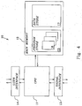
- Fig. 4 is a schematic drawing of a computer-implemented control system according to a preferred embodiment of the invention.
- the control system 10 basically comprises a computer or processor system in which one or more computer programs are being executed to perform the functions for monitoring and controlling the refuse collection system.
- the computer-based control system includes a CPU 11 or equivalent, a main memory 12, a conventional signal interface 13 and a conventional user interface 14.
- the main memory 12 has a program store 15 for computer programs 16 and a data store 17 for data.
- the control system is connected to the other components of the refuse collection system through conventional communication links and the control system utilizes the signal interface 13 for receiving signal information from the refuse collection system and for sending control signals to discharge valves, air inlet valves, sectioning valves and the main valve of the refuse collection system.
- the signal interface 13 is used for receiving load level information from one or more level sensors in the refuse collection system.
- This level information is then processed by the computer program(s) 16 running on the computer system, and the above prediction-based next-hop selection procedure, for example as described, is thereby executed, resulting in appropriate control signals being sent to the relevant discharge valves, air inlet valves and main valve for effectuating controlled emptying and collection of refuse.
- next-hop candidate itself is excluded from the considered set of branches when calculating the corresponding system consequence value.
- the lowest system consequence value 0.76 is associated with branch AV 2 and therefore the next-hop algorithm selects branch AV 2 .
- next-hop candidate branch AV 3 mainly because of the relatively high load level for DV3:3. It can also be seen that the least favorable choice is branch AV 1 since this branch has just been emptied and the predicted load levels are quite low.
Landscapes
- Engineering & Computer Science (AREA)
- Mechanical Engineering (AREA)
- Refuse Collection And Transfer (AREA)
- Processing Of Solid Wastes (AREA)
- Control Of Conveyors (AREA)
Claims (21)
- Verfahren zum Betrieb eines Vakuum-Müllsammelsystems (1) mit einem verzweigten Transportrohrsystem (5) mit einer Reihe von damit verbundenen Müllabwurfschächten (3), wobei das Verfahren die automatisierte Auswahl eines Sprungs zu einer nächsten Abzweigung zum Leeren des Mülls umfasst, dadurch gekennzeichnet, dass die automatisierte Auswahl auf einem der folgenden Verfahren basiert:- für jeden einer Reihe möglicher Kandidaten für den nächsten Sprung:a) Vorhersagen (S1) der Darstellungen der zukünftigen Füllstände der Müllabwurfschächte in einer Vielzahl von Abzweigungen, wobei sich die Vorhersagen zeitlich mindestens auf einen Sprung im Voraus erstrecken; undb) Bestimmen (S2) eines Wertes für die Auswirkung auf das System auf der Grundlage der vorhergesagten Darstellungen der zukünftigen Füllstände der Müllabwurfschächte; und- Auswählen des Sprungs zur nächsten Abzweigung unter denjenigen Kandidaten, die die günstigsten Werte für die Auswirkung auf das System haben.
- Verfahren nach Anspruch 1, wobei der Schritt (S2) des Bestimmens eines Wertes für die Auswirkung auf das System weiter folgende Schritte umfasst:- Durchführen der Gewichtung der vorhergesagten Darstellungen der zukünftigen Füllstände der Müllabwurfschächte mittels verschiedener Prioritätskoeffizienten; und- Bestimmen des Wertes für die Auswirkung auf das System auf der Grundlage der gewichteten Darstellungen der zukünftigen Füllstände.
- Verfahren nach Anspruch 1, wobei der Schritt (S2) des Bestimmens eines Wertes für die Auswirkung auf das System weiter folgende Schritte umfasst:- Bestimmen eines Wertes für die Auswirkung auf die Abzweigung für jede Abzweigung der Vielzahl von Abzweigungen auf der Grundlage der vorhergesagten Darstellungen der zukünftigen Füllstände der Müllabwurfschächte innerhalb der Abzweigung; und- Bestimmen des Wertes für die Auswirkung auf das System als eine Summe der Werte für die Auswirkung auf die Abzweigung.
- Verfahren nach Anspruch 1, wobei der Schritt (S1) des Vorhersagens der Darstellungen der zukünftigen Füllstände der Müllabwurfschächte den Schritt des Vorhersagens einer Darstellung eines zukünftigen Füllstandes für den Müllabwurfschacht zu einem für die nächste Leerung des Müllabwurfschachtes erwarteten Zeitpunkt unter Berücksichtigung eines Prognosepfades mit mindestens einem Sprung für jeden einer Reihe von Müllabwurfschächten innerhalb der Vielzahl von Abzweigungen umfasst.
- Verfahren nach Anspruch 1, wobei der Schritt (S1) des Vorhersagens der Darstellungen der zukünftigen Füllstände der Müllabwurfschächte den Schritt des Vorhersagens einer Darstellung eines zukünftigen Füllstandes für den Müllabwurfschacht auf der Grundlage von aufeinanderfolgenden Schätzungen des Füllstands im Müllabwurfschacht für jeden berücksichtigten Müllabwurfschacht umfasst.
- Verfahren nach Anspruch 1, wobei die vorgegebene Reihenfolge der Auswahl der Abzweigungen unterbrochen wird, wenn der Wert für die Auswirkung auf das System für einen Sprung zur gemäß der vorgegebenen Reihenfolge nächsten Abzweigung in einem bestimmten Maß weniger günstig ist als der Wert für die Auswirkung auf das System für einen anderen Kandidaten für den nächsten Sprung.
- Verfahren nach Anspruch 1, wobei der Schritt (S2) des Bestimmens eines Wertes für die Auswirkung auf das System Bsystem für jeden einer Reihe möglicher Kandidaten für den nächsten Sprung gemäß dem folgenden Algorithmus durchgeführt wird:


wobei Bl ein Wert für die Auswirkung auf die Abzweigung für die Abzweigung 1 ist, Rlk der vorhergesagte Füllstand für den Müllabwurfschaft k in Abzweigung 1 ist, J eine optionale Abzweigungs-spezifische Variable ist, die auf Null gesetzt werden kann, P ein Leistungsfaktor für die Kontrolle der Auswirkung des vorhergesagten Füllstandes auf den Wert für die Auswirkung auf die Abzweigung ist, Klk ein Prioritätskoeffizient für den Müllabwurfschacht k in der Abzweigung l ist und S die berücksichtigte Vielzahl von Abzweigungen ist. - Verfahren nach Anspruch 7, wobei der vorhergesagte Füllstand Rlk auf folgende Weise bestimmt wird:

wobei Flk eine Schätzung des aktuellen Füllstandes ist,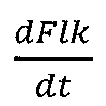
- Verfahren nach Anspruch 1, wobei die Abzweigung, die als Kandidat für den nächsten Sprung berücksichtigt wird, aus der Vielzahl der Abzweigungen ausgenommen wird.
- Regelungssystem (10) für die Regelung des Betriebs eines Vakuum-Müllsammelsystems (1) mit einem verzweigten Transportrohrsystem (5) mit einer Reihe von damit verbundenen Müllabwurfschächten (3), wobei das Regelungssystem so betrieben werden kann, dass der Sprung zu einer nächsten Abzweigung zum Leeren des Mülls gewählt werden kann, dadurch gekennzeichnet, dass das Regelungssystem (10) so angepasst ist, dass es das Verfahren nach einem der Ansprüche 1 - 9 ausführen kann, und Folgendes umfasst:- Mittel zum Bestimmen eines Wertes für die Auswirkung auf das System für jeden einer Reihe möglicher Kandidaten für den nächsten Sprung auf der Grundlage der vorhergesagten Darstellungen der zukünftigen Füllstände der Müllabwurfschächte in einer Vielzahl von Abzweigungen, wobei sich die Vorhersagen zeitlich mindestens auf einen Sprung im Voraus erstrecken; und- Mittel zum Auswählen des Sprungs zu einer nächsten Abzweigung unter denjenigen Kandidaten, die die günstigsten Werte für die Auswirkung auf das System haben.
- Regelungssystem nach Anspruch 10, wobei die Mittel zum Bestimmen eines Wertes für die Auswirkung auf das System weiter umfassen:- Mittel zum Durchführen der Gewichtung der vorhergesagten Darstellungen der zukünftigen Füllstände der Müllabwurfschächte mittels verschiedener Prioritätskoeffizienten; und- Mittel zum Bestimmen der Werte für die Auswirkung auf das System auf der Grundlage der gewichteten vorhergesagten Darstellungen zukünftiger Füllstände.
- Regelungssystem nach Anspruch 10, wobei die Mittel zum Bestimmen eines Wertes für die Auswirkung auf das System weiter Folgendes umfassen:- Mittel zum Bestimmen eines Wertes für die Auswirkung auf die Abzweigung für jede Abzweigung der Vielzahl von Abzweigungen auf der Grundlage der vorhergesagten Darstellungen zukünftiger Füllstände von Müllabwurfschächten innerhalb der Abzweigung; und- Mittel zum Bestimmen des Wertes für die Auswirkung auf das System als Summe der Werte für die Auswirkung auf die Abzweigung.
- Regelungssystem nach Anspruch 10, wobei die Mittel zum Bestimmen eines Wertes für die Auswirkung auf das System weiter umfassen:- Mittel zum Vorhersagen einer Darstellung eines zukünftigen Füllstandes für den Müllabwurfschacht zu einem für die nächste Leerung des Müllabwurfschachtes erwarteten Zeitpunkt für jeden einer Reihe von Müllabwurfschächten innerhalb der Vielzahl von Abzweigungen unter Berücksichtigung eines Prognosepfades mit mindestens einem Sprung; und- Mittel zum Bestimmen des Wertes für die Auswirkung auf das System auf der Grundlage der Darstellungen der zukünftigen Füllstände der Müllabwurfschächte.
- Regelungssystem nach Anspruch 13, wobei die Mittel zum Vorhersagen einer Darstellung eines zukünftigen Füllstandes des Müllabwurfschachtes so betrieben werden können, dass die Vorhersage auf der Grundlage aufeinanderfolgender Schätzungen des Füllstandes im Müllabwurfschacht durchgeführt wird.
- Regelungssystem nach Anspruch 10, wobei das Regelungssystem so betrieben werden kann, dass eine vorgegebene Reihenfolge für die Auswahl der Abzweigung unterbrochen werden kann, wenn der Wert für die Auswirkung auf das System für einen Sprung zur gemäß der vorgegebenen Reihenfolge nächsten Abzweigung in einem bestimmten Maß weniger günstig ist als der Wert für die Auswirkung auf das System für einen anderen Kandidaten für den nächsten Sprung.
- Regelungssystem nach Anspruch 10, wobei die Mittel zum Bestimmen eines Wertes für die Auswirkung auf das System Bsystem für jeden einer Reihe möglicher Kandidaten für den nächsten Sprung gemäß dem folgenden Algorithmus betrieben werden:


wobei Bl ein Wert für die Auswirkung auf die Abzweigung für die Abzweigung 1 ist, Rlk der vorhergesagte Füllstand für den Müllabwurfschaft k in Abzweigung 1 ist, J eine optionale Abzweigungs-spezifische Variable ist, die auf Null gesetzt werden kann, P ein Leistungsfaktor für die Kontrolle der Auswirkung des vorhergesagten Füllstandes auf den Wert für die Auswirkung auf die Abzweigung ist, Klk ein Prioritätskoeffizient für den Müllabwurfschacht k in der Abzweigung 1 ist und S die berücksichtigte Vielzahl von Abzweigungen ist. - Regelungssystem nach Anspruch 16, wobei das Regelungssystem zum Bestimmen des vorhergesagten Füllstands Rlk auf folgende Weise betrieben werden kann:

wobei Flk eine Schätzung des aktuellen Füllstandes ist,
- Regelungssystem nach Anspruch 10, wobei die Abzweigung, die als Kandidat für den nächsten Sprung berücksichtigt wird, aus der Vielzahl der Abzweigungen ausgenommen wird.
- Vakuum-Müllsammelsystems (1), das ein Regelungssystem (10) nach einem der Ansprüche 10 - 18 umfasst.
- Computerprogrammprodukt zur Regelung des Betriebs eines verzweigten Müllsammelsystems (1), wenn es auf einem Computer (11) läuft, wobei das Computerprogrammprodukt Programmmittel (16) umfasst, um den Computer die Auswahl eines Sprungs zu einer nächsten Abzweigung zum Leeren des Mülls gemäß dem folgenden Verfahren durchführen zu lassen:- für jeden einer Reihe möglicher Kandidaten für den nächsten Sprung:a) Vorhersagen der Darstellungen der zukünftigen Füllstände der Müllabwurfschächte in einer Vielzahl von Abzweigungen, wobei sich die Vorhersagen zeitlich mindestens auf einen Sprung im Voraus erstrecken; undb) Bestimmen eines Wertes für die Auswirkung auf das System auf der Grundlage der vorhergesagten Darstellungen der zukünftigen Füllstände der Müllabwurfschächte; und- Auswählen des Sprungs zu einer nächsten Abzweigung unter denjenigen Kandidaten, die die günstigsten Werte für die Auswirkung auf das System haben.
- Verfahren zum Betrieb eines Vakuum-Müllsammelsystems (1) mit einem verzweigten Transportrohrsystem (5) mit einer Reihe von damit verbundenen Müllabwurfschächten (3), wobei das Verfahren die automatisierte Auswahl eines Sprungs zu einer nächsten Abzweigung zum Leeren des Mülls umfasst, dadurch gekennzeichnet, dass die automatisierte Auswahl auf einem der folgenden Verfahren basiert:- für jeden einer Reihe möglicher Kandidaten für den nächsten Sprung:a) Vorhersagen der Darstellungen der zukünftigen Füllstände der Müllabwurfschächte innerhalb der Abzweigung, die ein Kandidat für den nächsten Sprung ist, wobei sich die Vorhersagen zeitlich mindestens auf einen Sprung im Voraus erstrecken; undb) Bestimmen eines Wertes für die Auswirkung auf die Abzweigung auf der Grundlage der vorhergesagten Darstellungen der zukünftigen Füllstände der Müllabwurfschächte; und- Auswählen des Sprungs zu einer nächsten Abzweigung unter denjenigen Kandidaten, die die höchsten Werte für die Auswirkung auf die Abzweigung haben.
Applications Claiming Priority (1)
| Application Number | Priority Date | Filing Date | Title |
|---|---|---|---|
| PCT/SE2003/000661 WO2004094270A1 (en) | 2003-04-24 | 2003-04-24 | Automated next-hop algorithm for a multi-branch refuse collection system |
Publications (2)
| Publication Number | Publication Date |
|---|---|
| EP1620331A1 EP1620331A1 (de) | 2006-02-01 |
| EP1620331B1 true EP1620331B1 (de) | 2016-02-24 |
Family
ID=33308702
Family Applications (1)
| Application Number | Title | Priority Date | Filing Date |
|---|---|---|---|
| EP03723559.5A Expired - Lifetime EP1620331B1 (de) | 2003-04-24 | 2003-04-24 | Automatisierter next-hop-algorithmus für ein verzweigtes müllsammelsystem |
Country Status (8)
| Country | Link |
|---|---|
| EP (1) | EP1620331B1 (de) |
| KR (1) | KR101101222B1 (de) |
| CN (1) | CN1747881B (de) |
| AU (1) | AU2003230489A1 (de) |
| DK (1) | DK1620331T3 (de) |
| ES (1) | ES2567434T3 (de) |
| NO (1) | NO330602B1 (de) |
| WO (1) | WO2004094270A1 (de) |
Families Citing this family (9)
| Publication number | Priority date | Publication date | Assignee | Title |
|---|---|---|---|---|
| ES2340209T3 (es) * | 2007-08-09 | 2010-05-31 | Ros Roca, S.A. | Vaciado neumatico desechos. |
| CN101792048B (zh) * | 2009-11-17 | 2014-05-14 | 联谊环卫设备有限公司 | 负压管道输送散落垃圾收集装置及方法 |
| ES2998033T3 (en) * | 2010-03-04 | 2025-02-18 | Envac Ab | Waste emptying control |
| ES2657699T3 (es) | 2010-06-23 | 2018-03-06 | Envac Ab | Sistema de recogida de residuos por vacío y método de operación de tal sistema |
| PT2666737T (pt) * | 2012-05-21 | 2022-08-16 | Ros Roca Envirotec S L | Método para a remoção de resíduos de uma rede de entradas de resíduos |
| CN110697422B (zh) * | 2019-10-30 | 2021-01-29 | 苏州克劳丽化妆品有限公司 | 一种颗粒真空吸料控制方法,装置及真空吸料系统 |
| US11999577B2 (en) | 2019-11-18 | 2024-06-04 | George Archambault | Methods and systems for managing airflow in conduits and pneumatic tubes |
| US11565892B2 (en) | 2020-07-08 | 2023-01-31 | Trans-Vac Systems LLC | Methods and systems for operation of a vacuum transport system |
| KR102553659B1 (ko) | 2021-06-07 | 2023-07-10 | 아이투엠 주식회사 | 의료폐기물 처리장치 |
Family Cites Families (6)
| Publication number | Priority date | Publication date | Assignee | Title |
|---|---|---|---|---|
| JP3084980B2 (ja) * | 1992-11-20 | 2000-09-04 | 石川島播磨重工業株式会社 | 高層建物のゴミ回収設備 |
| JP3075029B2 (ja) * | 1993-08-18 | 2000-08-07 | 石川島播磨重工業株式会社 | 高層建物のゴミ回収装置 |
| KR19980077546A (ko) * | 1997-04-21 | 1998-11-16 | 한스 스트롬 | 쓰레기 배출 방법 및 장치 |
| SE514550C2 (sv) * | 1999-07-16 | 2001-03-12 | Centralsug Ab | Adaptiv prediktionsbaserad styrning av ett vakuumarbetande avfallsuppsamlingssystem |
| SE514563C2 (sv) * | 1999-07-16 | 2001-03-12 | Centralsug Ab | En metod för avfallsuppsamlingssystem |
| CN1354117A (zh) * | 2001-12-21 | 2002-06-19 | 孙锡牛 | 一种有机垃圾中转再生方法及其收集、分流系统 |
-
2003
- 2003-04-24 AU AU2003230489A patent/AU2003230489A1/en not_active Abandoned
- 2003-04-24 KR KR1020057019128A patent/KR101101222B1/ko not_active Expired - Fee Related
- 2003-04-24 CN CN03826081.6A patent/CN1747881B/zh not_active Expired - Fee Related
- 2003-04-24 ES ES03723559.5T patent/ES2567434T3/es not_active Expired - Lifetime
- 2003-04-24 DK DK03723559.5T patent/DK1620331T3/en active
- 2003-04-24 WO PCT/SE2003/000661 patent/WO2004094270A1/en not_active Ceased
- 2003-04-24 EP EP03723559.5A patent/EP1620331B1/de not_active Expired - Lifetime
-
2005
- 2005-06-28 NO NO20053146A patent/NO330602B1/no not_active IP Right Cessation
Also Published As
| Publication number | Publication date |
|---|---|
| CN1747881A (zh) | 2006-03-15 |
| NO20053146L (no) | 2005-06-28 |
| WO2004094270A1 (en) | 2004-11-04 |
| EP1620331A1 (de) | 2006-02-01 |
| HK1086240A1 (en) | 2006-09-15 |
| KR101101222B1 (ko) | 2012-01-04 |
| CN1747881B (zh) | 2010-12-08 |
| DK1620331T3 (en) | 2016-04-18 |
| AU2003230489A1 (en) | 2004-11-19 |
| ES2567434T3 (es) | 2016-04-22 |
| NO330602B1 (no) | 2011-05-23 |
| KR20060004663A (ko) | 2006-01-12 |
Similar Documents
| Publication | Publication Date | Title |
|---|---|---|
| US9073706B2 (en) | Energy-efficient and reliable operation of a vacuum waste collection system | |
| EP1214260B1 (de) | Adaptive und prädiktive regelung eines systems zum sammeln von müll mittels vakuum | |
| EP1212246B1 (de) | System und verfahren zum sammeln von müll | |
| DK1620331T3 (en) | AUTOMATED NEXT-HOP ALGORITHM TO multi-branch WASTE COLLECTION SYSTEM | |
| EP2022731B1 (de) | Verfahren zur kontrollierten Abfallentsorgung | |
| HK1086240B (en) | Automated next-hop algorithm for a multi-branch refuse collection system | |
| EP2666737B1 (de) | Verfahren zur Beseitigung von Abfall aus einem Netzwerk von Mülleinlassen | |
| HK1181730B (en) | Vacuum waste collection system and method of operating such a system | |
| HK1046675B (en) | Adaptive prediction-based control of a vacuum refuse collection system |
Legal Events
| Date | Code | Title | Description |
|---|---|---|---|
| PUAI | Public reference made under article 153(3) epc to a published international application that has entered the european phase |
Free format text: ORIGINAL CODE: 0009012 |
|
| 17P | Request for examination filed |
Effective date: 20051124 |
|
| AK | Designated contracting states |
Kind code of ref document: A1 Designated state(s): AT BE BG CH CY CZ DE DK EE ES FI FR GB GR HU IE IT LI LU MC NL PT RO SE SI SK TR |
|
| RIN1 | Information on inventor provided before grant (corrected) |
Inventor name: BRANDEFELT, NIKLAS Inventor name: RYLENIUS, JAN |
|
| DAX | Request for extension of the european patent (deleted) | ||
| RAP1 | Party data changed (applicant data changed or rights of an application transferred) |
Owner name: ENVAC AB |
|
| 17Q | First examination report despatched |
Effective date: 20091005 |
|
| GRAP | Despatch of communication of intention to grant a patent |
Free format text: ORIGINAL CODE: EPIDOSNIGR1 |
|
| INTG | Intention to grant announced |
Effective date: 20151104 |
|
| GRAS | Grant fee paid |
Free format text: ORIGINAL CODE: EPIDOSNIGR3 |
|
| GRAA | (expected) grant |
Free format text: ORIGINAL CODE: 0009210 |
|
| AK | Designated contracting states |
Kind code of ref document: B1 Designated state(s): AT BE BG CH CY CZ DE DK EE ES FI FR GB GR HU IE IT LI LU MC NL PT RO SE SI SK TR |
|
| REG | Reference to a national code |
Ref country code: GB Ref legal event code: FG4D |
|
| REG | Reference to a national code |
Ref country code: CH Ref legal event code: EP |
|
| REG | Reference to a national code |
Ref country code: AT Ref legal event code: REF Ref document number: 776563 Country of ref document: AT Kind code of ref document: T Effective date: 20160315 |
|
| REG | Reference to a national code |
Ref country code: IE Ref legal event code: FG4D |
|
| REG | Reference to a national code |
Ref country code: DE Ref legal event code: R096 Ref document number: 60348575 Country of ref document: DE |
|
| REG | Reference to a national code |
Ref country code: DK Ref legal event code: T3 Effective date: 20160412 |
|
| REG | Reference to a national code |
Ref country code: ES Ref legal event code: FG2A Ref document number: 2567434 Country of ref document: ES Kind code of ref document: T3 Effective date: 20160422 |
|
| REG | Reference to a national code |
Ref country code: FR Ref legal event code: PLFP Year of fee payment: 14 |
|
| REG | Reference to a national code |
Ref country code: SE Ref legal event code: TRGR |
|
| REG | Reference to a national code |
Ref country code: NL Ref legal event code: MP Effective date: 20160224 |
|
| REG | Reference to a national code |
Ref country code: AT Ref legal event code: MK05 Ref document number: 776563 Country of ref document: AT Kind code of ref document: T Effective date: 20160224 |
|
| PG25 | Lapsed in a contracting state [announced via postgrant information from national office to epo] |
Ref country code: GR Free format text: LAPSE BECAUSE OF FAILURE TO SUBMIT A TRANSLATION OF THE DESCRIPTION OR TO PAY THE FEE WITHIN THE PRESCRIBED TIME-LIMIT Effective date: 20160525 |
|
| PG25 | Lapsed in a contracting state [announced via postgrant information from national office to epo] |
Ref country code: BE Free format text: LAPSE BECAUSE OF NON-PAYMENT OF DUE FEES Effective date: 20160430 Ref country code: PT Free format text: LAPSE BECAUSE OF FAILURE TO SUBMIT A TRANSLATION OF THE DESCRIPTION OR TO PAY THE FEE WITHIN THE PRESCRIBED TIME-LIMIT Effective date: 20160624 Ref country code: AT Free format text: LAPSE BECAUSE OF FAILURE TO SUBMIT A TRANSLATION OF THE DESCRIPTION OR TO PAY THE FEE WITHIN THE PRESCRIBED TIME-LIMIT Effective date: 20160224 Ref country code: NL Free format text: LAPSE BECAUSE OF FAILURE TO SUBMIT A TRANSLATION OF THE DESCRIPTION OR TO PAY THE FEE WITHIN THE PRESCRIBED TIME-LIMIT Effective date: 20160224 |
|
| PG25 | Lapsed in a contracting state [announced via postgrant information from national office to epo] |
Ref country code: EE Free format text: LAPSE BECAUSE OF FAILURE TO SUBMIT A TRANSLATION OF THE DESCRIPTION OR TO PAY THE FEE WITHIN THE PRESCRIBED TIME-LIMIT Effective date: 20160224 |
|
| REG | Reference to a national code |
Ref country code: DE Ref legal event code: R097 Ref document number: 60348575 Country of ref document: DE |
|
| PG25 | Lapsed in a contracting state [announced via postgrant information from national office to epo] |
Ref country code: SK Free format text: LAPSE BECAUSE OF FAILURE TO SUBMIT A TRANSLATION OF THE DESCRIPTION OR TO PAY THE FEE WITHIN THE PRESCRIBED TIME-LIMIT Effective date: 20160224 Ref country code: CZ Free format text: LAPSE BECAUSE OF FAILURE TO SUBMIT A TRANSLATION OF THE DESCRIPTION OR TO PAY THE FEE WITHIN THE PRESCRIBED TIME-LIMIT Effective date: 20160224 Ref country code: RO Free format text: LAPSE BECAUSE OF FAILURE TO SUBMIT A TRANSLATION OF THE DESCRIPTION OR TO PAY THE FEE WITHIN THE PRESCRIBED TIME-LIMIT Effective date: 20160224 |
|
| REG | Reference to a national code |
Ref country code: CH Ref legal event code: PL |
|
| PG25 | Lapsed in a contracting state [announced via postgrant information from national office to epo] |
Ref country code: LU Free format text: LAPSE BECAUSE OF FAILURE TO SUBMIT A TRANSLATION OF THE DESCRIPTION OR TO PAY THE FEE WITHIN THE PRESCRIBED TIME-LIMIT Effective date: 20160424 Ref country code: BE Free format text: LAPSE BECAUSE OF FAILURE TO SUBMIT A TRANSLATION OF THE DESCRIPTION OR TO PAY THE FEE WITHIN THE PRESCRIBED TIME-LIMIT Effective date: 20160224 |
|
| PLBE | No opposition filed within time limit |
Free format text: ORIGINAL CODE: 0009261 |
|
| STAA | Information on the status of an ep patent application or granted ep patent |
Free format text: STATUS: NO OPPOSITION FILED WITHIN TIME LIMIT |
|
| REG | Reference to a national code |
Ref country code: IE Ref legal event code: MM4A |
|
| PG25 | Lapsed in a contracting state [announced via postgrant information from national office to epo] |
Ref country code: LI Free format text: LAPSE BECAUSE OF NON-PAYMENT OF DUE FEES Effective date: 20160430 Ref country code: CH Free format text: LAPSE BECAUSE OF NON-PAYMENT OF DUE FEES Effective date: 20160430 |
|
| 26N | No opposition filed |
Effective date: 20161125 |
|
| PG25 | Lapsed in a contracting state [announced via postgrant information from national office to epo] |
Ref country code: SI Free format text: LAPSE BECAUSE OF FAILURE TO SUBMIT A TRANSLATION OF THE DESCRIPTION OR TO PAY THE FEE WITHIN THE PRESCRIBED TIME-LIMIT Effective date: 20160224 Ref country code: BG Free format text: LAPSE BECAUSE OF FAILURE TO SUBMIT A TRANSLATION OF THE DESCRIPTION OR TO PAY THE FEE WITHIN THE PRESCRIBED TIME-LIMIT Effective date: 20160524 |
|
| REG | Reference to a national code |
Ref country code: FR Ref legal event code: PLFP Year of fee payment: 15 |
|
| PG25 | Lapsed in a contracting state [announced via postgrant information from national office to epo] |
Ref country code: IE Free format text: LAPSE BECAUSE OF NON-PAYMENT OF DUE FEES Effective date: 20160424 |
|
| REG | Reference to a national code |
Ref country code: FR Ref legal event code: PLFP Year of fee payment: 16 |
|
| PG25 | Lapsed in a contracting state [announced via postgrant information from national office to epo] |
Ref country code: CY Free format text: LAPSE BECAUSE OF FAILURE TO SUBMIT A TRANSLATION OF THE DESCRIPTION OR TO PAY THE FEE WITHIN THE PRESCRIBED TIME-LIMIT Effective date: 20160224 Ref country code: HU Free format text: LAPSE BECAUSE OF FAILURE TO SUBMIT A TRANSLATION OF THE DESCRIPTION OR TO PAY THE FEE WITHIN THE PRESCRIBED TIME-LIMIT; INVALID AB INITIO Effective date: 20030424 |
|
| PG25 | Lapsed in a contracting state [announced via postgrant information from national office to epo] |
Ref country code: MC Free format text: LAPSE BECAUSE OF FAILURE TO SUBMIT A TRANSLATION OF THE DESCRIPTION OR TO PAY THE FEE WITHIN THE PRESCRIBED TIME-LIMIT Effective date: 20160224 Ref country code: TR Free format text: LAPSE BECAUSE OF FAILURE TO SUBMIT A TRANSLATION OF THE DESCRIPTION OR TO PAY THE FEE WITHIN THE PRESCRIBED TIME-LIMIT Effective date: 20160224 |
|
| PGFP | Annual fee paid to national office [announced via postgrant information from national office to epo] |
Ref country code: DK Payment date: 20200327 Year of fee payment: 18 Ref country code: FI Payment date: 20200317 Year of fee payment: 18 |
|
| PGFP | Annual fee paid to national office [announced via postgrant information from national office to epo] |
Ref country code: DE Payment date: 20200317 Year of fee payment: 18 |
|
| PGFP | Annual fee paid to national office [announced via postgrant information from national office to epo] |
Ref country code: IT Payment date: 20200317 Year of fee payment: 18 |
|
| PGFP | Annual fee paid to national office [announced via postgrant information from national office to epo] |
Ref country code: FR Payment date: 20210316 Year of fee payment: 19 |
|
| PGFP | Annual fee paid to national office [announced via postgrant information from national office to epo] |
Ref country code: GB Payment date: 20210316 Year of fee payment: 19 |
|
| REG | Reference to a national code |
Ref country code: DE Ref legal event code: R119 Ref document number: 60348575 Country of ref document: DE |
|
| REG | Reference to a national code |
Ref country code: FI Ref legal event code: MAE |
|
| REG | Reference to a national code |
Ref country code: DK Ref legal event code: EBP Effective date: 20210430 |
|
| PG25 | Lapsed in a contracting state [announced via postgrant information from national office to epo] |
Ref country code: FI Free format text: LAPSE BECAUSE OF NON-PAYMENT OF DUE FEES Effective date: 20210424 Ref country code: DE Free format text: LAPSE BECAUSE OF NON-PAYMENT OF DUE FEES Effective date: 20211103 |
|
| PG25 | Lapsed in a contracting state [announced via postgrant information from national office to epo] |
Ref country code: DK Free format text: LAPSE BECAUSE OF NON-PAYMENT OF DUE FEES Effective date: 20210430 |
|
| PGFP | Annual fee paid to national office [announced via postgrant information from national office to epo] |
Ref country code: SE Payment date: 20220314 Year of fee payment: 20 |
|
| PGFP | Annual fee paid to national office [announced via postgrant information from national office to epo] |
Ref country code: ES Payment date: 20220503 Year of fee payment: 20 |
|
| GBPC | Gb: european patent ceased through non-payment of renewal fee |
Effective date: 20220424 |
|
| PG25 | Lapsed in a contracting state [announced via postgrant information from national office to epo] |
Ref country code: GB Free format text: LAPSE BECAUSE OF NON-PAYMENT OF DUE FEES Effective date: 20220424 Ref country code: FR Free format text: LAPSE BECAUSE OF NON-PAYMENT OF DUE FEES Effective date: 20220430 |
|
| REG | Reference to a national code |
Ref country code: ES Ref legal event code: FD2A Effective date: 20230503 |
|
| REG | Reference to a national code |
Ref country code: SE Ref legal event code: EUG |
|
| PG25 | Lapsed in a contracting state [announced via postgrant information from national office to epo] |
Ref country code: IT Free format text: LAPSE BECAUSE OF NON-PAYMENT OF DUE FEES Effective date: 20200424 |
|
| PG25 | Lapsed in a contracting state [announced via postgrant information from national office to epo] |
Ref country code: ES Free format text: LAPSE BECAUSE OF EXPIRATION OF PROTECTION Effective date: 20230425 |
|
| PG25 | Lapsed in a contracting state [announced via postgrant information from national office to epo] |
Ref country code: IT Free format text: LAPSE BECAUSE OF NON-PAYMENT OF DUE FEES Effective date: 20210424 |