EP1620171B1 - An einer leitung integrierter und implantierbarer medizinischer sensor versorgt durch einen piezoelektrischen transformater - Google Patents
An einer leitung integrierter und implantierbarer medizinischer sensor versorgt durch einen piezoelektrischen transformater Download PDFInfo
- Publication number
- EP1620171B1 EP1620171B1 EP04749563A EP04749563A EP1620171B1 EP 1620171 B1 EP1620171 B1 EP 1620171B1 EP 04749563 A EP04749563 A EP 04749563A EP 04749563 A EP04749563 A EP 04749563A EP 1620171 B1 EP1620171 B1 EP 1620171B1
- Authority
- EP
- European Patent Office
- Prior art keywords
- voltage
- piezoelectric transformer
- implantable
- sensor
- lead
- Prior art date
- Legal status (The legal status is an assumption and is not a legal conclusion. Google has not performed a legal analysis and makes no representation as to the accuracy of the status listed.)
- Expired - Lifetime
Links
Images
Classifications
-
- A—HUMAN NECESSITIES
- A61—MEDICAL OR VETERINARY SCIENCE; HYGIENE
- A61N—ELECTROTHERAPY; MAGNETOTHERAPY; RADIATION THERAPY; ULTRASOUND THERAPY
- A61N1/00—Electrotherapy; Circuits therefor
- A61N1/18—Applying electric currents by contact electrodes
- A61N1/32—Applying electric currents by contact electrodes alternating or intermittent currents
- A61N1/36—Applying electric currents by contact electrodes alternating or intermittent currents for stimulation
- A61N1/362—Heart stimulators
- A61N1/365—Heart stimulators controlled by a physiological parameter, e.g. heart potential
- A61N1/36514—Heart stimulators controlled by a physiological parameter, e.g. heart potential controlled by a physiological quantity other than heart potential, e.g. blood pressure
- A61N1/36542—Heart stimulators controlled by a physiological parameter, e.g. heart potential controlled by a physiological quantity other than heart potential, e.g. blood pressure controlled by body motion, e.g. acceleration
Definitions
- the invention relates to implantable medical devices and, more particularly, to implantable medical devices that include lead-based sensors.
- Implantable medical devices such as implantable cardiac pacemakers, pacemaker-cardioverter-defibrillators, neurostimulators, gastric stimulators, drug pumps, loop recorders, and the like, generally make use of battery power to support the output and functionality of such devices.
- An IMD is typically designed for use over a period of years, and therefore power efficiency and associated battery consumption is a significant concern.
- Some IMDs receive signals from sensors carried by implantable leads.
- a sensor may be responsive to a sensed condition in the body, such as electrical activity, blood pressure, blood chemistry or a mechanical property. Sensors responsive to sensed conditions may detect or measure a quantity of clinical significance. Some sensors require consume power to support sensor operation. Examples of powered sensors include ultrasonic sensors, infrared sensors, cameras and the like.
- powered sensors receive power from a battery, which may be positioned with an IMD housing.
- An IMD delivers power to a sensor by way of a lead that includes a conductor.
- powered sensors contribute to power consumption and battery drain, and can compromise IMD longevity.
- WO 01/09640 discloses a piezo-electric transformer.
- the document US 2002/0183800 discloses a lead with a sensor and with two power sources.
- the invention provides an implantable medical device comprising:
- the invention provides a method comprising:
- the invention is directed to an IMD having a piezoelectric transformer to power a lead-based sensor.
- the IMD powers the piezoelectric transformer with a low amplitude signal.
- the piezoelectric transformer serves to convert the voltage level of the low amplitude signal to a higher voltage level to drive the sensor. produced by a battery in the IMD to voltage levels appropriate for IMD operation.
- a piezoelectric transformer offers small size and low profile, as well as operational efficiency, and permits the IMD to transmit a low amplitude signal to a remote sensor deployed within an implantable lead.
- the piezoelectric transformer provides electrical isolation that reduces electromagnetic interference among different sensors.
- the piezoelectric transformer includes two or more piezoelectric resonators.
- the piezoelectric resonators are mechanically coupled to one another, but electrically insulated.
- An input circuit coupled to a battery in the IMD, generates an input signal near a resonant frequency of an input resonator, and transmits the signal along the length of the lead to the piezoelectric transformer via an electrical conductor.
- the input circuit may be a pulse frequency modulation circuit.
- the input resonator receives the input signal, and generates mechanical vibration due to the piezoelectric converse effect.
- An output resonator transduces the mechanical vibration to generate an output signal at a second voltage level, due to the piezoelectric direct effect.
- the output resonator applies the output signal to a sensor, either directly or via an output stage circuit, thereby powering the sensor.
- the IMD uses the output signal from the piezoelectric transformer to support sensor operation.
- the IMD may be, for example, an implantable cardiac pacemaker, pacemaker-cardioverter-defibrillator, a neurostimulator, a drug pump, a loop recorder, or the like.
- the IMD applies the output signal generated by the piezoelectric transformer to power a variety of sensors including ultrasonic sensors, infrared sensors, cameras and the like.
- the invention provides an implantable medical device comprising a battery to deliver a first voltage, an input circuit to generate an input signal derived from the first voltage, a piezoelectric transformer to convert the first voltage to a second voltage greater than the first voltage, wherein the piezoelectric transformer includes a first resonator that generates mechanical vibration in response to the input signal, and a second resonator that generates an output signal in response to the mechanical vibration, a sensor powered by the second voltage, and an implantable lead, wherein the sensor is disposed within the lead.
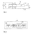
- piezoelectric transformer 10 serves to convert a first voltage to a second voltage higher than the first voltage within an IMD.
- the first voltage is generated with power delivered by a battery within the IMD.
- the second voltage (V OUT ) is applied to support operation of a lead-based sensor, i.e., a sensor carried by an implantable lead associated with the IMD.
- Examples of powered sensors suitable for use with piezoelectric transformer 10 include ultrasonic sensors, infrared sensors, cameras and the like.
- Piezoelectric transformer 10 offers a small size and low profile, facilitating placement of the piezoelectric transformer within an implantable lead. In addition, piezoelectric transformer 10 offers good power efficiency. For example, some commercially available piezoelectric transformers are known to offer 80 to 90 percent power efficiency. In addition, piezoelectric transformer 10 provides electrical isolation that reduces electromagnetic interference among different sensors.
- the first and second resonators 13, 15 of piezoelectric transformer 10 are mechanically coupled to one another, but electrically insulated from one another.
- Input circuit 12 coupled to a battery (not shown in FIG. 1 ), generates the input signal V IN near a resonant frequency of the input resonator.
- the input resonator 13 generates mechanical vibration, due to the piezoelectric converse effect.
- the output resonator 15 transduces the mechanical vibration to generate output signal V OUT at a second voltage level, due to the piezoelectric direct effect.
- FIG. 2 is a block diagram illustrating an IMD 22 incorporating a piezoelectric transformer (PZT).
- IMD 22 includes a battery 24 that provides power to an input circuit 26. The power delivered by battery 24 has a first voltage level.
- An implantable lead 28 carries a PZT 30 and a powered sensor 32.
- Input circuit 26 generates an input signal to drive PZT 30 at or near a resonant frequency of the PZT.
- PZT 30 receives the input signal via electrical conductors within the implantable lead. In response, PZT 30 generates an output signal at a second voltage greater than the first voltage.
- PZT 30 applies the second voltage to power sensor 32, either directly or via an output circuit.
- Sensor 32 uses the power provided by PZT 30 for operation. For example, if sensor 32 is an ultrasonic sensor, it uses the power to emit ultrasonic energy. Sensor 32 then captures reflections of the ultrasonic energy to sense physiological parameters such as blood flow, blood pressure, valve closure in the case of a cardiac device, or the like.
- the first voltage provided by input circuit 26 may be less than or equal to approximately 50 millivolts. More particularly, the first voltage may be in the range of approximately 10 to 50 millivolts. Similarly, the input signal generated by input circuit 26 may generate an ac signal with a peak amplitude on the order of 10 to 50 millivolts.
- the second voltage delivered by PZT 30, however, may be in excess of approximately 3 volts. For example, a typically commercially available piezoelectric transformer having a transformation ratio of 65 will transform a 50 millivolt input signal to a level of approximately 3.25 volts. The resonance frequency of a typical piezoelectric transformer may in the range of approximately 50 kHz to 100kHz. Hence, the first voltage delivered by battery 24 may be less than fifty percent of the second voltage and, in many, cases less than twenty percent of the second voltage.
- the second voltage may be provided directly from PZT 30.
- the second voltage may be generated by an output circuit.
- PZT 30 may be used to power multiple sensors within an implantable lead.
- the lead may incorporated multiple sensors of a common type, of different types of sensors, each of which can be powered by PZT 30.
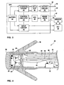
- FIG. 3 is a block diagram illustrating IMD 22 incorporating a lead-based sensor powered by a piezoelectric transformer.
- IMD 22 is depicted as an implanted cardioverter-defibrillator (ICD) for purposes of illustration.
- ICD implanted cardioverter-defibrillator
- IMD 22 may be an implantable cardiac pacemaker, neurostimulator, a gastric stimulator, a drug pump, a loop recorder, or the like.
- IMD 22 includes battery 24, input circuit 26, PZT 30, and sensor 32.
- IMD 22 includes a charging circuit 34 coupled to battery 24, a hold capacitor 36 charged by charging circuit 34, and an output circuit 38 that drives one or more stimulation electrodes deployed within the heart via implantable leads 40, 42 to deliver shocks.
- Control circuitry 44 controls charging circuit 34 and output circuit 38 to deliver cardioversion and/or defibrillation shocks via stimulation leads 40, 42.
- lead 40 may be carried by a right atrial lead and lead 42 may be carried by a right ventricular lead.
- Leads 40, 42 may include both stimulation electrodes and sense electrodes.
- One or more sense amplifiers 46 receive physiological signals from powered sensor 32, deployed on lead 28.
- sense amplifiers 46 may receive other physiological signals via other leads, such as lead 47.
- sense amplifiers 46 may process cardiac signals obtained from one or more sense electrodes deployed on lead 47.
- the sense electrodes and powered sensor 32 are deployed within the heart via implantable leads 47, 28, respectively.
- one or more sense electrodes may be carried by a right atrial lead and one or more sense electrodes may be carried by a right ventricular lead.
- the powered sensor may be carried by an atrial or ventricular lead.
- An analog-to-digital converter (ADC) 48 converts the sensed physiological signals to digital values for processing and analysis by control circuitry 44, which may include a microprocessor, digital signal processor, ASIC, FPGA, or other equivalent logic circuitry. Control circuitry 44 may be respond to the rate, timing, amplitude, or morphology of the physiological signals in controlling charging circuit 34 and output circuit 38 to deliver cardioversion and defibrillation shocks, as well as in controlling blanking intervals for sense amplifiers 46. IMD 22 further includes a telemetry circuit (not shown) for wireless communication with an external programmer.
- input circuit 26 In operation, input circuit 26 generates an input signal having a frequency approximately matched to a resonant frequency of the input resonator of PZT 30.
- the input signal may have a sinusoidal waveform, and an amplitude substantially less than the operating power level required by sensor 32.
- input circuit 26 may include closed loop feedback to detect the output voltage produced by PZT 30, and adjust the frequency or amplitude of the input signal based on the detected output voltage. In this manner, input circuit 26 causes PZT 30 a controlled, substantially constant output voltage.
- PZT 30 offers a small size that permits the PZT to be placed within an implantable lead to powered sensor 32 carried by the lead.
- PZT 30 also may enable the realization of a sensor 32 that is resistant to circuit-induced inter-channel cross-current.
- inclusion of PZT 30 provides electrical isolation, and thereby circumvents possible current paths from sensor 32 to other sensors. Reduced interference promotes more accurate sensing on non-stimulation channels.
- PZT 30 can help to protect sensor 32 from electromagnetic interference.
- piezoelectric elements are insensitive to electromagnetic interference. Accordingly, sensor performance is unaffected by presence of electromagnetic interference induced in the electrical conductors extending along the lead.
- PZT 30 may serve to better isolate sensor 32 from electrical interference caused by MRI procedures or emissions from equipment within the environment occupied by the patient.
- FIG. 4 is a cross-sectional side view of a distal end of an implantable lead 28 carrying a sensor 32 and a piezoelectric transformer 30 to power the sensor.
- the distal end of lead 28 may include an electrode 50, which transmits or receives electrical signals or pacing stimuli from IMD 22 (not shown in FIG. 4 ) via a conductor 52.
- Electrode 50 is coupled to an insulating sheath 54.
- Tines 56 projecting from sheath 54 present a fixation mechanism that anchors the distal end of lead 28 in cardiac tissue.
- PZT 30 is disposed inside the distal end of lead 14. As shown in FIG. 4 , PZT 30 may be housed inside a capsule 58 and may be electrically coupled to an input circuit in IMD 22 via one or more conductors 60, 62. Conductor 60, 62 may, for example, supply a low voltage signal at approximately the resonant frequency of an input resonator in PZT 30. Conductors 52, 60, 62 may be carried within lead 28 by insulative conduits 64, 66, 68, respectively.
- Sensor 32 is electrically coupled to the output resonator of PZT 30 via conductor 70.
- the input resonator in PZT 30 converts the low voltage input signal transmitted by conductors 60, 62 into mechanical energy, which is then transduced by the output resonator to produce the output signal with an increased voltage.
- Sensor 32 receives the output signal from PZT 30 via conductor 70. In this way, PZT 30 powers sensor 32.
- Sensor 32 applies power from PZT 30 to detect or measure sensed conditions.
- sensor 32 transmits sensed signals to IMD 22 via conductor 72, housed in insulative conduit 74.
- PZT 30 need not be housed in a capsule, for example, and need not be directly coupled to sensor 32. Rather, intermediate output circuitry may stand between PZT 30 and sensor 32 to shape or condition the output signal.
- the invention may be practiced with leads of various configurations, including leads with bipolar electrodes, leads with fixation mechanisms other than tines, and leads configured to provide steroid elution.
Landscapes
- Health & Medical Sciences (AREA)
- Cardiology (AREA)
- Heart & Thoracic Surgery (AREA)
- Life Sciences & Earth Sciences (AREA)
- Biomedical Technology (AREA)
- Biophysics (AREA)
- Physiology (AREA)
- Engineering & Computer Science (AREA)
- Hematology (AREA)
- Nuclear Medicine, Radiotherapy & Molecular Imaging (AREA)
- Radiology & Medical Imaging (AREA)
- Animal Behavior & Ethology (AREA)
- General Health & Medical Sciences (AREA)
- Public Health (AREA)
- Veterinary Medicine (AREA)
- Electrotherapy Devices (AREA)
- Arrangements For Transmission Of Measured Signals (AREA)
Claims (16)
- Implantierbare medizinische Vorrichtung (22) mit:einer Batterie (24), um eine erste Spannung zu liefern;einem piezoelektrischen Wandler (10), um die erste Spannung in eine zweite Spannung, die größer ist als die erste Spannung, umzuwandeln bzw. umzusetzen; undeinem Sensor (32), der durch die zweite Spannung mit Leistung versorgt wird; undferner mit einer implantierbaren Leitung (28), dadurch gekennzeichnet, dass der Sensor und der piezoelektrische Wandler innerhalb der Leitung angeordnet sind.
- Vorrichtung nach Anspruch 1, die ferner eine Eingangsschaltung (26) enthält, um den piezoelektrischen Wandler mit einem Eingangssignal anzusteuern.
- Vorrichtung nach einem vorhergehenden Anspruch, wobei der piezoelektrische Wandler einen ersten Resonator (13), der in Reaktion auf das Eingangssignal mechanische Schwingungen erzeugt, und einen zweiten Resonator (15), der in Reaktion auf die mechanischen Schwingungen ein Ausgangssignal erzeugt, enthält.
- Vorrichtung nach Anspruch 3, wobei das Eingangssignal eine Frequenz hat, die etwa gleich einer Resonanzfrequenz des ersten Resonators ist.
- Vorrichtung nach einem vorhergehenden Anspruch, wobei die Vorrichtung einen implantierbaren Herzschrittmacher, einen implantierbaren Kardioverter-Defibrillator, einen implantierbaren Neurostimulator, einen implantierbaren Gastro-Stimulator, eine implantierbare Arzneimittelpumpe oder einen implantierbaren Schleifenrekorder enthält.
- Vorrichtung nach einem vorhergehenden Anspruch, wobei die erste Spannung weniger als fünfzig Prozent der zweiten Spannung beträgt.
- Vorrichtung nach einem vorhergehenden Anspruch, wobei die erste Spannung weniger als zwanzig Prozent der zweiten Spannung beträgt.
- Vorrichtung nach einem vorhergehenden Anspruch, wobei der Sensor einen Ultraschallsensor oder einen Infrarotsensor oder eine Kamera enthält.
- Vorrichtung nach einem vorhergehenden Anspruch, wobei die zweite Spannung größer oder gleich 3 Volt ist.
- Vorrichtung nach einem vorhergehenden Anspruch, wobei die erste Spannung kleiner oder gleich 50 Millivolt ist.
- Vorrichtung nach Anspruch 1, ferner mit einer Eingangsschaltung, um den piezoelektrischen Wandler mit einem Eingangssignal anzusteuern, und Leitern, die innerhalb der Leitung verlaufen, um die Eingangsschaltung mit dem piezoelektrischen Wandler elektrisch zu koppeln.
- Vorrichtung nach Anspruch 3 oder einem hiervon abhängigen Anspruch, wobei
der Sensor mit dem piezoelektrischen Wandler elektrisch gekoppelt ist. - Verfahren, das umfasst:Umsetzen einer ersten Spannung in eine zweite Spannung mittels eines piezoelektrischen Wandlers, wobei die zweite Spannung größer ist als die erste Spannung; undAnlegen der zweiten Spannung an einen Sensor in einer implantierbaren medizinischen Vorrichtung;wobei der Sensor innerhalb einer implantierbaren Leitung angeordnet ist und wobei der piezoelektrische Wandler innerhalb der Leitung angeordnet ist.
- Verfahren nach Anspruch 13, wobei das Umsetzen der ersten Spannung in eine zweite Spannung das Ansteuern eines ersten Resonators des piezoelektrischen Wandlers mit einem ersten Signal, um mechanische Schwingungen zu erzeugen, und das Umwandeln der mechanischen Schwingungen mittels eines zweiten Resonators des piezoelektrischen Wandlers, um ein zweites Signal mit der zweiten Spannung zu erzeugen, umfasst.
- Verfahren nach Anspruch 13, wobei die Vorrichtung einen implantierbaren Herzschrittmacher oder einen implantierbaren Kardioverter-Defibrillator oder einen implantierbaren Neurostimulator oder einen implantierbaren Gastro-Stimulator oder eine implantierbare Arzneimittelpumpe oder einen implantierbaren Schleifenrekorder enthält.
- Verfahren nach Anspruch 13, wobei der Sensor einen Ultraschallsensor oder einen Infrarotsensor oder eine Kamera enthält.
Applications Claiming Priority (2)
| Application Number | Priority Date | Filing Date | Title |
|---|---|---|---|
| US10/424,584 US7203551B2 (en) | 2003-04-25 | 2003-04-25 | Implantable lead-based sensor powered by piezoelectric transformer |
| PCT/US2004/009842 WO2004096344A2 (en) | 2003-04-25 | 2004-03-31 | Implantable lead-based sensor powered by piezoelectric transformer |
Publications (2)
| Publication Number | Publication Date |
|---|---|
| EP1620171A2 EP1620171A2 (de) | 2006-02-01 |
| EP1620171B1 true EP1620171B1 (de) | 2010-11-17 |
Family
ID=33299399
Family Applications (1)
| Application Number | Title | Priority Date | Filing Date |
|---|---|---|---|
| EP04749563A Expired - Lifetime EP1620171B1 (de) | 2003-04-25 | 2004-03-31 | An einer leitung integrierter und implantierbarer medizinischer sensor versorgt durch einen piezoelektrischen transformater |
Country Status (4)
| Country | Link |
|---|---|
| US (1) | US7203551B2 (de) |
| EP (1) | EP1620171B1 (de) |
| DE (1) | DE602004030102D1 (de) |
| WO (1) | WO2004096344A2 (de) |
Cited By (2)
| Publication number | Priority date | Publication date | Assignee | Title |
|---|---|---|---|---|
| US9607759B2 (en) | 2013-03-13 | 2017-03-28 | Medtronic, Inc. | Implantable medical device including a molded planar transformer |
| US11844628B2 (en) | 2013-03-13 | 2023-12-19 | Medtronic, Inc. | Method of forming a transformer assembly |
Families Citing this family (64)
| Publication number | Priority date | Publication date | Assignee | Title |
|---|---|---|---|---|
| US8467874B2 (en) * | 2000-04-11 | 2013-06-18 | The Board Of Regents Of The University Of Texas System | Gastrointestinal electrical stimulation |
| EP1272250A4 (de) * | 2000-04-11 | 2003-07-09 | Univ Texas | Gastrointestinale elektrische stimulation |
| US8761903B2 (en) * | 2000-10-11 | 2014-06-24 | The Board Of Regents Of The University Of Texas | Gastrointestinal electrical stimulation |
| US7283874B2 (en) | 2000-10-16 | 2007-10-16 | Remon Medical Technologies Ltd. | Acoustically powered implantable stimulating device |
| US7024248B2 (en) * | 2000-10-16 | 2006-04-04 | Remon Medical Technologies Ltd | Systems and methods for communicating with implantable devices |
| US6764446B2 (en) | 2000-10-16 | 2004-07-20 | Remon Medical Technologies Ltd | Implantable pressure sensors and methods for making and using them |
| US20040215243A1 (en) * | 2003-04-25 | 2004-10-28 | Houben Richard P.M. | Implantable medical device with piezoelectric transformer |
| CA2623616A1 (en) | 2005-11-29 | 2007-06-07 | Surgi-Vision, Inc. | Mri-guided localization and/or lead placement systems, related methods, devices and computer program products |
| US8078278B2 (en) * | 2006-01-10 | 2011-12-13 | Remon Medical Technologies Ltd. | Body attachable unit in wireless communication with implantable devices |
| US7650185B2 (en) | 2006-04-25 | 2010-01-19 | Cardiac Pacemakers, Inc. | System and method for walking an implantable medical device from a sleep state |
| US9020597B2 (en) | 2008-11-12 | 2015-04-28 | Endostim, Inc. | Device and implantation system for electrical stimulation of biological systems |
| US12343530B2 (en) | 2006-05-18 | 2025-07-01 | Paras Holdings, Llc | Device and implantation system for electrical stimulation of biological systems |
| US11577077B2 (en) | 2006-10-09 | 2023-02-14 | Endostim, Inc. | Systems and methods for electrical stimulation of biological systems |
| US20150224310A1 (en) | 2006-10-09 | 2015-08-13 | Endostim, Inc. | Device and Implantation System for Electrical Stimulation of Biological Systems |
| US9345879B2 (en) | 2006-10-09 | 2016-05-24 | Endostim, Inc. | Device and implantation system for electrical stimulation of biological systems |
| US9724510B2 (en) | 2006-10-09 | 2017-08-08 | Endostim, Inc. | System and methods for electrical stimulation of biological systems |
| US8709631B1 (en) | 2006-12-22 | 2014-04-29 | Pacesetter, Inc. | Bioelectric battery for implantable device applications |
| US20080171941A1 (en) * | 2007-01-12 | 2008-07-17 | Huelskamp Paul J | Low power methods for pressure waveform signal sampling using implantable medical devices |
| US8388670B1 (en) | 2007-01-16 | 2013-03-05 | Pacesetter, Inc. | Sensor/lead systems for use with implantable medical devices |
| EP2139556B1 (de) * | 2007-03-26 | 2014-04-23 | Remon Medical Technologies Ltd. | Vorgespannter akustischer schalter für ein implantierbares medizinprodukt |
| US8175677B2 (en) * | 2007-06-07 | 2012-05-08 | MRI Interventions, Inc. | MRI-guided medical interventional systems and methods |
| US8060218B2 (en) * | 2007-08-02 | 2011-11-15 | Synecor, Llc | Inductive element for intravascular implantable devices |
| US8315689B2 (en) | 2007-09-24 | 2012-11-20 | MRI Interventions, Inc. | MRI surgical systems for real-time visualizations using MRI image data and predefined data of surgical tools |
| US8195272B2 (en) | 2007-09-24 | 2012-06-05 | MRI Interventions, Inc. | MRI-compatible patches and methods for using the same |
| US8548569B2 (en) * | 2007-09-24 | 2013-10-01 | MRI Interventions, Inc. | Head fixation assemblies for medical procedures |
| WO2009042130A2 (en) | 2007-09-24 | 2009-04-02 | Surgivision, Inc. | Mri-guided medical interventional systems and methods |
| US8099150B2 (en) * | 2007-09-24 | 2012-01-17 | MRI Interventions, Inc. | MRI-compatible head fixation frame with cooperating head coil apparatus |
| WO2009067205A1 (en) * | 2007-11-21 | 2009-05-28 | Surgi-Vision, Inc. | Methods, systems and computer program products for positioning a guidance apparatus relative to a patient |
| US8565885B2 (en) * | 2008-01-30 | 2013-10-22 | The Board Of Regents Of The University Of Texas System | Ileal electrical stimulation |
| DE102008016364A1 (de) * | 2008-03-29 | 2009-10-01 | Biotronik Crm Patent Ag | Signalleitung einer implantierbaren elektromedizinischen Anordnung |
| US20090312650A1 (en) * | 2008-06-12 | 2009-12-17 | Cardiac Pacemakers, Inc. | Implantable pressure sensor with automatic measurement and storage capabilities |
| US8798761B2 (en) * | 2008-06-27 | 2014-08-05 | Cardiac Pacemakers, Inc. | Systems and methods of monitoring the acoustic coupling of medical devices |
| US20100023091A1 (en) * | 2008-07-24 | 2010-01-28 | Stahmann Jeffrey E | Acoustic communication of implantable device status |
| WO2010062538A1 (en) | 2008-10-27 | 2010-06-03 | Cardiac Pacemakers, Inc. | Methods and systems for recharging implantable devices |
| US9631610B2 (en) * | 2008-12-04 | 2017-04-25 | Deep Science, Llc | System for powering devices from intraluminal pressure changes |
| US9353733B2 (en) * | 2008-12-04 | 2016-05-31 | Deep Science, Llc | Device and system for generation of power from intraluminal pressure changes |
| US9759202B2 (en) | 2008-12-04 | 2017-09-12 | Deep Science, Llc | Method for generation of power from intraluminal pressure changes |
| US9526418B2 (en) * | 2008-12-04 | 2016-12-27 | Deep Science, Llc | Device for storage of intraluminally generated power |
| US9567983B2 (en) | 2008-12-04 | 2017-02-14 | Deep Science, Llc | Method for generation of power from intraluminal pressure changes |
| US20100249882A1 (en) * | 2009-03-31 | 2010-09-30 | Medtronic, Inc. | Acoustic Telemetry System for Communication with an Implantable Medical Device |
| EP2251700A1 (de) * | 2009-05-12 | 2010-11-17 | Kamstrup A/S | Magnetisch immuner Verbrauchsmesser |
| CN102470250B (zh) | 2009-08-11 | 2015-02-25 | 皇家飞利浦电子股份有限公司 | 用于在心脏刺激装置中使用的非磁性高压充电系统 |
| US20110137390A1 (en) * | 2009-12-08 | 2011-06-09 | Hill Gerard J | System and method for protecting implanted medical devices from interfering radiated fields |
| US8447404B2 (en) | 2010-03-05 | 2013-05-21 | Endostim, Inc. | Device and implantation system for electrical stimulation of biological systems |
| US11717681B2 (en) | 2010-03-05 | 2023-08-08 | Endostim, Inc. | Systems and methods for treating gastroesophageal reflux disease |
| EP2603284B1 (de) | 2010-08-09 | 2015-07-08 | PI-Harvest Holding AG | Medizinisches system, pieoelektrisches kit, und verfahren zur herstellung |
| US9084859B2 (en) | 2011-03-14 | 2015-07-21 | Sleepnea Llc | Energy-harvesting respiratory method and device |
| WO2012142539A1 (en) | 2011-04-14 | 2012-10-18 | Endostim, Inc. | Systems and methods for treating gastroesophageal reflux disease |
| US9037245B2 (en) | 2011-09-02 | 2015-05-19 | Endostim, Inc. | Endoscopic lead implantation method |
| US9925367B2 (en) | 2011-09-02 | 2018-03-27 | Endostim, Inc. | Laparoscopic lead implantation method |
| EP2888000A4 (de) | 2012-08-23 | 2016-07-06 | Endostim Inc | Vorrichtung und implantationssystem zur elektrischen stimulation biologischer systeme |
| US9192446B2 (en) | 2012-09-05 | 2015-11-24 | MRI Interventions, Inc. | Trajectory guide frame for MRI-guided surgeries |
| US9498619B2 (en) | 2013-02-26 | 2016-11-22 | Endostim, Inc. | Implantable electrical stimulation leads |
| WO2015034867A2 (en) | 2013-09-03 | 2015-03-12 | Endostim, Inc. | Methods and systems of electrode polarity switching in electrical stimulation therapy |
| EP2875844B1 (de) | 2013-11-25 | 2018-01-03 | BIOTRONIK SE & Co. KG | Implantierbare Elektrodeneinrichtung, insbesondere für kardiologische Geräte, wie Herzschrittmacher |
| US9682234B2 (en) | 2014-11-17 | 2017-06-20 | Endostim, Inc. | Implantable electro-medical device programmable for improved operational life |
| US10238876B2 (en) | 2015-09-04 | 2019-03-26 | Medtronic, Inc. | Stimulation aggressor management for biomedical signal acquisition systems |
| WO2017105491A1 (en) * | 2015-12-18 | 2017-06-22 | Intel Corporation | Noise resilient, low-power heart rate sensing techniques |
| WO2018094207A1 (en) | 2016-11-17 | 2018-05-24 | Endostim, Inc. | Modular stimulation system for the treatment of gastrointestinal disorders |
| WO2019157103A1 (en) | 2016-11-17 | 2019-08-15 | Endostim, Inc. | Electrical stimulation system for the treatment of gastrointestinal disorders |
| EP3606603A1 (de) | 2017-04-06 | 2020-02-12 | Endostim, Inc. | Implantierbare oberflächenelektroden und implantationsverfahren |
| US10905497B2 (en) | 2017-04-21 | 2021-02-02 | Clearpoint Neuro, Inc. | Surgical navigation systems |
| GB2563440B (en) * | 2017-06-16 | 2019-06-05 | Cardiaccs As | Securing a sensor at the heart |
| KR102741179B1 (ko) * | 2021-06-02 | 2024-12-10 | 주식회사 에스비솔루션 | 동물 체온 연속 측정 방법 및 시스템 |
Family Cites Families (15)
| Publication number | Priority date | Publication date | Assignee | Title |
|---|---|---|---|---|
| US3421512A (en) * | 1965-12-15 | 1969-01-14 | Int Rectifier Corp | Implanted electrical device with biological power supply |
| US4023562A (en) | 1975-09-02 | 1977-05-17 | Case Western Reserve University | Miniature pressure transducer for medical use and assembly method |
| US4109644A (en) * | 1977-01-12 | 1978-08-29 | The United States Of America As Represented By The United States National Aeronautics And Space Administration | Miniature implantable ultrasonic echosonometer |
| US4432372A (en) | 1981-08-28 | 1984-02-21 | Medtronic, Inc. | Two-lead power/signal multiplexed transducer |
| US4690143A (en) * | 1984-07-19 | 1987-09-01 | Cordis Corporation | Pacing lead with piezoelectric power generating means |
| CN86103803B (zh) * | 1986-06-05 | 1987-11-18 | 北京信息工程学院 | 静电场治疗装置 |
| US5620479A (en) * | 1992-11-13 | 1997-04-15 | The Regents Of The University Of California | Method and apparatus for thermal therapy of tumors |
| US5484404A (en) * | 1994-05-06 | 1996-01-16 | Alfred E. Mann Foundation For Scientific Research | Replaceable catheter system for physiological sensors, tissue stimulating electrodes and/or implantable fluid delivery systems |
| US5807258A (en) * | 1997-10-14 | 1998-09-15 | Cimochowski; George E. | Ultrasonic sensors for monitoring the condition of a vascular graft |
| US6486588B2 (en) * | 1997-12-30 | 2002-11-26 | Remon Medical Technologies Ltd | Acoustic biosensor for monitoring physiological conditions in a body implantation site |
| DK176073B1 (da) * | 1998-03-03 | 2006-04-03 | Limiel Aps | Piezoelektrisk transformer |
| GB2352931A (en) | 1999-07-29 | 2001-02-07 | Marconi Electronic Syst Ltd | Piezoelectric tag |
| US7191008B2 (en) | 2001-05-30 | 2007-03-13 | Medtronic, Inc. | Implantable medical device with a dual power source |
| US20040174098A1 (en) * | 2003-03-04 | 2004-09-09 | Yu-Hsiang Hsu | Optimized piezoelectric transformer apparatus with maximum energy conversion efficiency |
| US20040215243A1 (en) * | 2003-04-25 | 2004-10-28 | Houben Richard P.M. | Implantable medical device with piezoelectric transformer |
-
2003
- 2003-04-25 US US10/424,584 patent/US7203551B2/en not_active Expired - Fee Related
-
2004
- 2004-03-31 DE DE602004030102T patent/DE602004030102D1/de not_active Expired - Lifetime
- 2004-03-31 WO PCT/US2004/009842 patent/WO2004096344A2/en not_active Ceased
- 2004-03-31 EP EP04749563A patent/EP1620171B1/de not_active Expired - Lifetime
Cited By (2)
| Publication number | Priority date | Publication date | Assignee | Title |
|---|---|---|---|---|
| US9607759B2 (en) | 2013-03-13 | 2017-03-28 | Medtronic, Inc. | Implantable medical device including a molded planar transformer |
| US11844628B2 (en) | 2013-03-13 | 2023-12-19 | Medtronic, Inc. | Method of forming a transformer assembly |
Also Published As
| Publication number | Publication date |
|---|---|
| WO2004096344A3 (en) | 2005-01-27 |
| US20040215279A1 (en) | 2004-10-28 |
| US7203551B2 (en) | 2007-04-10 |
| DE602004030102D1 (de) | 2010-12-30 |
| EP1620171A2 (de) | 2006-02-01 |
| WO2004096344A2 (en) | 2004-11-11 |
Similar Documents
| Publication | Publication Date | Title |
|---|---|---|
| US7203551B2 (en) | Implantable lead-based sensor powered by piezoelectric transformer | |
| US4543955A (en) | System for controlling body implantable action device | |
| US9095284B2 (en) | Distance measurement using implantable acoustic transducers | |
| US8784310B2 (en) | Vascular pressure sensor with electrocardiogram electrodes | |
| CN105492069B (zh) | 具有改进的导电通信的无引线起搏器 | |
| US8788035B2 (en) | Leadless cardiac pacemaker triggered by conductive communication | |
| US6298269B1 (en) | Cardiac rhythm management system with ultrasound for autocapture or other applications | |
| CN102791327B (zh) | 可植入医疗装置电池 | |
| US8777863B2 (en) | Implantable medical device with internal piezoelectric energy harvesting | |
| US9270137B2 (en) | System and method for controlling charging energy delivered to an implantable medical device | |
| JP2009511214A5 (de) | ||
| US20100317978A1 (en) | Implantable medical device housing modified for piezoelectric energy harvesting | |
| US8506495B2 (en) | Implantable medical devices with piezoelectric anchoring member | |
| US20040158294A1 (en) | Self-powered implantable element | |
| JP2014530713A (ja) | 伝導通信方式のリードレス心臓ペースメーカ | |
| WO2006036667A1 (en) | Implantable medical lead | |
| US10695572B2 (en) | System for recharging a rechargeable implantable medical device including an implantable recharging bridge | |
| US8688223B2 (en) | Implantable medical device impedance measurement module for communication with one or more lead-borne devices | |
| US8388670B1 (en) | Sensor/lead systems for use with implantable medical devices | |
| US20040215243A1 (en) | Implantable medical device with piezoelectric transformer | |
| CN110709131B (zh) | 具有用于将功率发射到另一植入式医疗设备的栓系式发射线圈的植入式医疗设备 | |
| US9555254B2 (en) | Implantable medical device with communication by way of physical connector, system and method therefore |
Legal Events
| Date | Code | Title | Description |
|---|---|---|---|
| PUAI | Public reference made under article 153(3) epc to a published international application that has entered the european phase |
Free format text: ORIGINAL CODE: 0009012 |
|
| 17P | Request for examination filed |
Effective date: 20051125 |
|
| AK | Designated contracting states |
Kind code of ref document: A2 Designated state(s): CH DE FR LI NL SE |
|
| DAX | Request for extension of the european patent (deleted) | ||
| RBV | Designated contracting states (corrected) |
Designated state(s): CH DE FR LI NL SE |
|
| RAP3 | Party data changed (applicant data changed or rights of an application transferred) |
Owner name: MEDTRONIC, INC. |
|
| 17Q | First examination report despatched |
Effective date: 20080429 |
|
| GRAP | Despatch of communication of intention to grant a patent |
Free format text: ORIGINAL CODE: EPIDOSNIGR1 |
|
| GRAS | Grant fee paid |
Free format text: ORIGINAL CODE: EPIDOSNIGR3 |
|
| GRAA | (expected) grant |
Free format text: ORIGINAL CODE: 0009210 |
|
| AK | Designated contracting states |
Kind code of ref document: B1 Designated state(s): CH DE FR LI NL SE |
|
| REG | Reference to a national code |
Ref country code: CH Ref legal event code: EP |
|
| REF | Corresponds to: |
Ref document number: 602004030102 Country of ref document: DE Date of ref document: 20101230 Kind code of ref document: P |
|
| REG | Reference to a national code |
Ref country code: NL Ref legal event code: VDEP Effective date: 20101117 |
|
| PG25 | Lapsed in a contracting state [announced via postgrant information from national office to epo] |
Ref country code: SE Free format text: LAPSE BECAUSE OF FAILURE TO SUBMIT A TRANSLATION OF THE DESCRIPTION OR TO PAY THE FEE WITHIN THE PRESCRIBED TIME-LIMIT Effective date: 20101117 Ref country code: NL Free format text: LAPSE BECAUSE OF FAILURE TO SUBMIT A TRANSLATION OF THE DESCRIPTION OR TO PAY THE FEE WITHIN THE PRESCRIBED TIME-LIMIT Effective date: 20101117 |
|
| PLBE | No opposition filed within time limit |
Free format text: ORIGINAL CODE: 0009261 |
|
| STAA | Information on the status of an ep patent application or granted ep patent |
Free format text: STATUS: NO OPPOSITION FILED WITHIN TIME LIMIT |
|
| 26N | No opposition filed |
Effective date: 20110818 |
|
| REG | Reference to a national code |
Ref country code: CH Ref legal event code: PL |
|
| REG | Reference to a national code |
Ref country code: DE Ref legal event code: R097 Ref document number: 602004030102 Country of ref document: DE Effective date: 20110818 |
|
| PG25 | Lapsed in a contracting state [announced via postgrant information from national office to epo] |
Ref country code: LI Free format text: LAPSE BECAUSE OF NON-PAYMENT OF DUE FEES Effective date: 20110331 Ref country code: CH Free format text: LAPSE BECAUSE OF NON-PAYMENT OF DUE FEES Effective date: 20110331 |
|
| REG | Reference to a national code |
Ref country code: FR Ref legal event code: PLFP Year of fee payment: 13 |
|
| PGFP | Annual fee paid to national office [announced via postgrant information from national office to epo] |
Ref country code: FR Payment date: 20160328 Year of fee payment: 13 |
|
| PGFP | Annual fee paid to national office [announced via postgrant information from national office to epo] |
Ref country code: DE Payment date: 20160331 Year of fee payment: 13 |
|
| REG | Reference to a national code |
Ref country code: DE Ref legal event code: R119 Ref document number: 602004030102 Country of ref document: DE |
|
| REG | Reference to a national code |
Ref country code: FR Ref legal event code: ST Effective date: 20171130 |
|
| PG25 | Lapsed in a contracting state [announced via postgrant information from national office to epo] |
Ref country code: DE Free format text: LAPSE BECAUSE OF NON-PAYMENT OF DUE FEES Effective date: 20171003 Ref country code: FR Free format text: LAPSE BECAUSE OF NON-PAYMENT OF DUE FEES Effective date: 20170331 |