EP1619387A2 - Radial piston pump - Google Patents
Radial piston pump Download PDFInfo
- Publication number
- EP1619387A2 EP1619387A2 EP05104012A EP05104012A EP1619387A2 EP 1619387 A2 EP1619387 A2 EP 1619387A2 EP 05104012 A EP05104012 A EP 05104012A EP 05104012 A EP05104012 A EP 05104012A EP 1619387 A2 EP1619387 A2 EP 1619387A2
- Authority
- EP
- European Patent Office
- Prior art keywords
- crank chamber
- shaft seal
- radial piston
- piston pump
- safety valve
- Prior art date
- Legal status (The legal status is an assumption and is not a legal conclusion. Google has not performed a legal analysis and makes no representation as to the accuracy of the status listed.)
- Granted
Links
Images
Classifications
-
- F—MECHANICAL ENGINEERING; LIGHTING; HEATING; WEAPONS; BLASTING
- F04—POSITIVE - DISPLACEMENT MACHINES FOR LIQUIDS; PUMPS FOR LIQUIDS OR ELASTIC FLUIDS
- F04B—POSITIVE-DISPLACEMENT MACHINES FOR LIQUIDS; PUMPS
- F04B1/00—Multi-cylinder machines or pumps characterised by number or arrangement of cylinders
- F04B1/04—Multi-cylinder machines or pumps characterised by number or arrangement of cylinders having cylinders in star- or fan-arrangement
- F04B1/0404—Details or component parts
- F04B1/0448—Sealing means, e.g. for shafts or housings
-
- F—MECHANICAL ENGINEERING; LIGHTING; HEATING; WEAPONS; BLASTING
- F04—POSITIVE - DISPLACEMENT MACHINES FOR LIQUIDS; PUMPS FOR LIQUIDS OR ELASTIC FLUIDS
- F04B—POSITIVE-DISPLACEMENT MACHINES FOR LIQUIDS; PUMPS
- F04B17/00—Pumps characterised by combination with, or adaptation to, specific driving engines or motors
- F04B17/05—Pumps characterised by combination with, or adaptation to, specific driving engines or motors driven by internal-combustion engines
-
- F—MECHANICAL ENGINEERING; LIGHTING; HEATING; WEAPONS; BLASTING
- F04—POSITIVE - DISPLACEMENT MACHINES FOR LIQUIDS; PUMPS FOR LIQUIDS OR ELASTIC FLUIDS
- F04B—POSITIVE-DISPLACEMENT MACHINES FOR LIQUIDS; PUMPS
- F04B49/00—Control, e.g. of pump delivery, or pump pressure of, or safety measures for, machines, pumps, or pumping installations, not otherwise provided for, or of interest apart from, groups F04B1/00 - F04B47/00
- F04B49/10—Other safety measures
Definitions
- the invention relates to a radial piston pump with a pump housing, in which a first crank chamber is formed, in which a drive shaft is rotatably mounted, which is drivable via a, mounted in a second crank chamber of an internal combustion engine, crankshaft. Between the first crank chamber and the second crank chamber, a shaft seal is formed, which seals the two crank chambers against each other.
- a generic radial piston pump is already known from DE 103 00 144 B3.
- the radial piston pump has a drive shaft, which is rotatably mounted on plain bearings in a first crank chamber.
- the drive shaft is formed with an eccentric portion, on which a lifting ring is arranged, on which several, preferably three, at a distance of 120 degrees each staggered pump piston are supported.
- the drive shaft protrudes from the pump housing and is coupled via a connecting element with the camshaft of an internal combustion engine.
- a connecting element is, for example, an Oldham coupling.
- the camshaft is rotatably mounted in a second crank chamber filled with engine oil.
- the invention is characterized in that the shaft seal consists of at least one shaft seal and at least one roller bearing provided with sealing washers, wherein the shaft seal and the shaft bearing are arranged one behind the other on the drive shaft such that the rolling bearing is arranged closer to the crank chamber of the camshaft than the Shaft seal and wherein between the shaft seal and the rolling bearing a gap is formed, from which branches off a relief hole in which a safety valve is arranged.
- the intermediate space thus forms a neutral space between the first crank chamber of the radial piston pump and the second crank chamber of the camshaft.
- the safety valve ensures that fuel or engine oil can flow through the relief bore only when a predetermined opening pressure is exceeded.
- the relief well can thus be connected in the simplest case with the environment without that negative effects on the environment are to be feared. It is also possible that the relief hole is connected to an additional container, so that under no circumstances engine oil or fuel can reach the environment.
- An advantageous embodiment of the invention provides that the opening pressure of the safety valve is greater than the operating pressure in the crankcase of the camshaft and smaller than the operating pressure in the crankcase of the radial piston pump.
- the seals of the bearings are often not completely tight due to their simple design. This will get engine oil into the neutral space. However, this does not constitute a disturbance because the engine oil continues to flow over the shaft seal in relation to the crankcase the radial piston pump is sealed. In the event of a failure of the shaft seal, where the fuel under higher pressure, leak through the shaft seal and would enter the crankcase of the camshaft on the non-fully sealing washers of the bearings, opens the safety valve and ensures that no fuel in the crankcase of Camshaft can get.
- a particularly advantageous embodiment of the invention provides that the opening pressure of the safety valve is between 20 and 100 mbar, preferably between 20 and 30 mbar. This opening pressure has proved to be particularly suitable for radial piston pumps in common-rail injection systems.
- the safety valve is designed as a spring-loaded ball valve or tongue valve. These valves are simple and inexpensive and ensure safe operation. However, it is also conceivable, in particular for low pressure differences between the first and the second crank chamber, to use a valve filled with a heavier medium riser pipe.
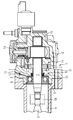
- the figure shows schematically an axial section through a radial piston pump according to the invention.
- the radial piston pump has a high-pressure pump unit 13 and a prefeed pump 14 which are arranged on the common drive shaft 3 in the pump housing 1.
- the pump housing 1 is formed as a two-part pot housing, consisting of a housing base 16 and a flange 17.
- the drive shaft is mounted one end via a roller bearing 9 and other ends via a sliding bearing 15 in the pump housing 1.
- a first crank chamber 2 is formed in which fuel is at a pressure of about 500 mbar.
- the drive shaft 3 protrudes from the pump housing 1 and is connected via a connecting element 14 with the camshaft 5.
- the camshaft 5 is rotatably mounted in a second crank chamber 4.
- the second crank chamber 4 is filled with engine oil, wherein the oil pressure is about ⁇ 20mbar from the environment.
- the first crank chamber 2 is sealed to the second crank chamber 4 via a shaft seal 6.
- the shaft seal 6 is intended to prevent fuel from entering the second crank chamber 4 of the internal combustion engine from the first crank chamber 2. This could cause the engine to stop.
- the shaft seal 6 consists of at least one shaft sealing ring 7 and provided with sealing discs 8 bearings 9.
- the shaft seal 7 and the rolling bearing 9 are successively spaced from each other, arranged on the drive shaft 3, such that the rolling bearing is located closer to the second crank chamber 4
- This gap 10 is referred to below as the neutral space 10, since it is sealed on both sides.
- From the neutral space 10 performs a relief hole 11 in the area.
- a safety valve 12 is arranged, which opens at a specified pressure and thus releases the connection to the environment.
- the fuel flows into the neutral space 10 at a pressure of up to 500 bar. This pressure is sufficient to open the safety valve 12. As a result, the fuel can flow via the Endlastungsbohrung 11 in the environment. By opening the safety valve 12 is thus avoided that the fuel on the sealing disks 8 of the rolling bearing 9 can get away in the second crank chamber 4 of the camshaft 5.
- the safety valve 12 is designed such that the opening pressure is greater than the operating pressure occurring in the second crank chamber 4 during normal operation and less than the operating pressure in the first crank chamber 2 occurring during normal operation. This ensures that only in the case of a leaking shaft seal 7, or a pressure in the neutral space, which increases sharply for other reasons, the safety valve opens to avoid major damage to the engine. On the other hand, a slight leakage of the sealing disc 8 does not lead to opening the safety valve 12, so that in this case no engine oil can get into the environment.
- an opening pressure of the safety valve between 20 and 100 mbar has proven to be expedient.
- the opening pressure is between 20 and 30 mbar. This ensures a very sensitive response of the safety valve.
- the safety valve 12 may preferably be formed as a simple, spring-loaded ball valve or as a tongue valve. These valves are extremely robust and inexpensive. It is also conceivable to use a filled with a heavy medium riser.
- the proposed shaft seal ensures safe operation of the radial piston pump and reliably prevents leakage of engine oil during normal operation.
- the proposed shaft seal is of course not only suitable for radial piston pumps but suitable for any high-pressure sealing of rooms with different pressures.
Landscapes
- Engineering & Computer Science (AREA)
- Mechanical Engineering (AREA)
- General Engineering & Computer Science (AREA)
- Chemical & Material Sciences (AREA)
- Combustion & Propulsion (AREA)
- Fuel-Injection Apparatus (AREA)
- Details Of Reciprocating Pumps (AREA)
Abstract
Description
Die Erfindung betrifft eine Radialkolbenpumpe mit einem Pumpengehäuse, in dem ein erster Kurbelraum ausgebildet ist, in dem drehbar eine Antriebswelle gelagert ist, die über eine, in einem zweiten Kurbelraum eines Verbrennungsmotors gelagerte, Kurbelwelle antreibbar ist. Zwischen dem ersten Kurbelraum und dem zweiten Kurbelraum ist eine Wellenabdichtung ausgebildet, die die beiden Kurbelräume gegeneinander abdichtet.The invention relates to a radial piston pump with a pump housing, in which a first crank chamber is formed, in which a drive shaft is rotatably mounted, which is drivable via a, mounted in a second crank chamber of an internal combustion engine, crankshaft. Between the first crank chamber and the second crank chamber, a shaft seal is formed, which seals the two crank chambers against each other.
Eine gattungsgemäße Radialkolbenpumpe ist bereits aus der DE 103 00 144 B3 bekannt. Die Radialkolbenpumpe weist eine Antriebswelle auf, die über Gleitlager drehbar in einem ersten Kurbelraum gelagert ist. Die Antriebswelle ist mit einem Exzenterabschnitt ausgebildet, auf dem ein Hubring angeordnet ist an dem sich mehrere, vorzugsweise drei, in einem Abstand von je 120 Grad zueinander versetzte Pumpenkolben abstützen. Die Antriebswelle ragt aus dem Pumpengehäuse hinaus und ist über ein Verbindungselement mit der Nockenwelle eines Verbrennungsmotors gekoppelt. Als Verbindungselement eignet sich beispielsweise eine Oldham-Kupplung. Die Nockenwelle ist drehbar in einem mit Motorenöl gefüllten zweiten Kurbelraum gelagert. Bei einer Undichtigkeit der Radialkolbenpumpe kann, auf Grund von Druckunterschieden zwischen dem ersten und dem zweiten Kurbelraum, Kraftstoff in den zweiten Kurbelraum angesaugt werden, wodurch der Verbrennungsmotor u.U. nicht mehr abstellbar ist. Dies ist unter allen Umständen zu vermeiden.A generic radial piston pump is already known from DE 103 00 144 B3. The radial piston pump has a drive shaft, which is rotatably mounted on plain bearings in a first crank chamber. The drive shaft is formed with an eccentric portion, on which a lifting ring is arranged, on which several, preferably three, at a distance of 120 degrees each staggered pump piston are supported. The drive shaft protrudes from the pump housing and is coupled via a connecting element with the camshaft of an internal combustion engine. As a connecting element is, for example, an Oldham coupling. The camshaft is rotatably mounted in a second crank chamber filled with engine oil. In the event of a leakage of the radial piston pump, due to pressure differences between the first and the second crank chamber, fuel can be sucked into the second crank chamber, as a result of which the internal combustion engine may also be sucked. can not be turned off. This should be avoided at all costs.
Ausgehend vom Stand der Technik, ist es somit Aufgabe der Erfindung, eine sichere Abdichtung zwischen dem Kurbelraum der Radialkolbenpumpe und dem Kurbelraum der Nockenwelle zu gewährleisten.Based on the prior art, it is therefore an object of the invention to ensure a secure seal between the crankcase of the radial piston pump and the crankcase of the camshaft.
Die Aufgabe wird gelöst durch die Merkmale des unabhängigen Patentanspruchs.The object is solved by the features of the independent claim.
Vorteilhafte Ausgestaltungen der Erfindung, welche einzeln oder in Kombination miteinander einsetzbar sind, sind in den Unteransprüchen gekennzeichnet.Advantageous embodiments of the invention, which are used individually or in combination with each other, are characterized in the subclaims.
Die Erfindung zeichnet sich dadurch aus, dass die Wellenabdichtung aus wenigstens einem Wellendichtring und wenigstens einem mit Dichtscheiben versehenen Wälzlager besteht, wobei der Wellendichtring und das Wellenlager hintereinander auf der Antriebswelle angeordnet sind derart, dass das Wälzlager näher an dem Kurbelraum der Nockenwelle angeordnet ist als der Wellendichtring und wobei zwischen dem Wellendichtring und dem Wälzlager ein Zwischenraum ausgebildet ist, von dem aus eine Entlastungsbohrung abzweigt, in der ein Sicherheitsventil angeordnet ist. Der Zwischenraum bildet somit einen Neutralraum zwischen dem ersten Kurbelraum der Radialkolbenpumpe und dem zweiten Kurbelraum der Nockenwelle aus. Das Sicherheitsventil sorgt dafür, dass nur beim Überschreiten eines vorgegebenen Öffnungsdrucks Kraftstoff bzw. Motoröl durch die Entlastungsbohrung hindurch strömen kann. Die Entlastungsbohrung kann somit im einfachsten Fall mit der Umgebung verbunden sein ohne, dass negative Auswirkungen für die Umwelt zu befürchten sind. Es ist auch möglich, dass die Entlastungsbohrung mit einem zusätzlichen Auffangbehälter verbunden ist, so dass unter keinen Umständen Motoröl bzw. Kraftstoff an die Umgebung gelangen kann.The invention is characterized in that the shaft seal consists of at least one shaft seal and at least one roller bearing provided with sealing washers, wherein the shaft seal and the shaft bearing are arranged one behind the other on the drive shaft such that the rolling bearing is arranged closer to the crank chamber of the camshaft than the Shaft seal and wherein between the shaft seal and the rolling bearing a gap is formed, from which branches off a relief hole in which a safety valve is arranged. The intermediate space thus forms a neutral space between the first crank chamber of the radial piston pump and the second crank chamber of the camshaft. The safety valve ensures that fuel or engine oil can flow through the relief bore only when a predetermined opening pressure is exceeded. The relief well can thus be connected in the simplest case with the environment without that negative effects on the environment are to be feared. It is also possible that the relief hole is connected to an additional container, so that under no circumstances engine oil or fuel can reach the environment.
Eine vorteilhafte Ausgestaltung der Erfindung sieht vor, dass der Öffnungsdruck des Sicherheitsventils größer als der Betriebsdruck im Kurbelraum der Nockenwelle und kleine als der Betriebsdruck im Kurbelraum der Radialkolbenpumpe ist. Die Dichtscheiben der Wälzlager sind aufgrund ihrer einfachen Bauart häufig nicht absolut dicht. Dadurch gelangt Motoröl in den Neutralraum. Dies stellt jedoch keine Störung dar, da das Motoröl über den Wellendichtring weiterhin gegenüber dem Kurbelraum der Radialkolbenpumpe abgedichtet ist. Bei einem Defekt des Wellendichtrings, bei dem der unter höherem Druck stehende Kraftstoff, über den Wellendichtring austreten und über die nicht vollständig dichtenden Dichtscheiben der Wälzlager in den Kurbelraum der Nockenwelle eintreten würde, öffnet das Sicherheitsventil und sorgt dafür, dass kein Kraftstoff in den Kurbelraum der Nockenwelle gelangen kann.An advantageous embodiment of the invention provides that the opening pressure of the safety valve is greater than the operating pressure in the crankcase of the camshaft and smaller than the operating pressure in the crankcase of the radial piston pump. The seals of the bearings are often not completely tight due to their simple design. This will get engine oil into the neutral space. However, this does not constitute a disturbance because the engine oil continues to flow over the shaft seal in relation to the crankcase the radial piston pump is sealed. In the event of a failure of the shaft seal, where the fuel under higher pressure, leak through the shaft seal and would enter the crankcase of the camshaft on the non-fully sealing washers of the bearings, opens the safety valve and ensures that no fuel in the crankcase of Camshaft can get.
Eine besonders vorteilhafte Ausgestaltung der Erfindung sieht vor, dass der Öffnungsdruck des Sicherheitsventils zwischen 20 und 100 mbar, vorzugsweise zwischen 20 und 30 mbar liegt. Dieser Öffnungsdruck hat sich für Radialkolbenpumpen bei Common-Rail Einspritzsystemen als besonders geeignet erwiesen.A particularly advantageous embodiment of the invention provides that the opening pressure of the safety valve is between 20 and 100 mbar, preferably between 20 and 30 mbar. This opening pressure has proved to be particularly suitable for radial piston pumps in common-rail injection systems.
In einer bevorzugten Ausgestaltung der Erfindung ist das Sicherheitsventil als federbelastetes Kugelventil oder Zungenventil ausgebildet. Diese Ventile sind einfach und preiswert aufgebaut und gewährleisten eine sichere Funktion. Es ist aber auch denkbar, insbesondere bei geringen Druckdifferenzen zwischen dem ersten und dem zweiten Kurbelraum, als Ventil ein mit schwererem Medium gefülltes Steigrohr zu verwenden.In a preferred embodiment of the invention, the safety valve is designed as a spring-loaded ball valve or tongue valve. These valves are simple and inexpensive and ensure safe operation. However, it is also conceivable, in particular for low pressure differences between the first and the second crank chamber, to use a valve filled with a heavier medium riser pipe.
Zusammenfassend lässt sich feststellen, dass durch die vorgeschlagene Wellenabdichtung eine besonders sichere Abdichtung der Kurbelräume von Radialkolbenpumpe und Nockenwelle gegeneinander erreicht wird. Die Abdichtung ist besonders umweltschonend, da nur im Falle eines Schadens des Wellendichtrings das Sicherheitsventil in der Entlastungsbohrung öffnet und den Neutralraum mit der Umgebung verbindet. Dadurch wird ein ansaugen von Kraftstoff in den Kurbelraum der Nockenwelle verhindert was ansonsten zu schweren Motorschäden führen könnte.In summary, it can be stated that a particularly reliable sealing of the crank chambers of radial piston pump and camshaft is achieved against each other by the proposed shaft seal. The seal is particularly environmentally friendly, because only in case of damage to the shaft seal, the safety valve opens in the relief hole and connects the neutral space with the environment. This prevents the intake of fuel into the crank chamber of the camshaft, which could otherwise lead to serious engine damage.
Ein Ausführungsbeispiel, sowie weitere Vorteile der Erfindung werden im Folgenden anhand der einzigen Zeichnung erläutert.An embodiment, as well as further advantages of the invention will be explained below with reference to the single drawing.
Die Figur zeigt schematisch einen Axialschnitt durch eine erfindungsgemäße Radialkolbenpumpe. Die Radialkolbenpumpe weist eine Hochdruckpumpeneinheit 13 sowie eine Vorförderpumpe 14 auf die auf der gemeinsamen Antriebswelle 3 im Pumpengehäuse 1 angeordnet sind. Das Pumpengehäuse 1 ist als zweiteiliges Topfgehäuse, bestehend aus einem Gehäusegrundkörper 16 und einem Flansch 17, ausgebildet. Die Antriebswelle ist einen Ends über ein Wälzlager 9 und anderen Ends über ein Gleitlager 15 im Pumpengehäuse 1 gelagert. Im Pumpengehäuse 1 ist ein erster Kurbelraum 2 ausgebildet in dem sich Kraftstoff mit einem Druck von etwa 500mbar befindet. Die Antriebswelle 3 ragt aus dem Pumpengehäuse 1 hinaus und ist über ein Verbindungselement 14 mit der Nockenwelle 5 verbunden. Die Nockenwelle 5 ist in einem zweiten Kurbelraum 4 drehbar gelagert. Der zweite Kurbelraum 4 ist mit Motoröl gefüllt, wobei der Öldruck etwa ± 20mbar gegenüber der Umgebung beträgt. Der erste Kurbelraum 2 ist zum zweiten Kurbelraum 4 über eine Wellenabdichtung 6 abgedichtet. Die Wellenabdichtung 6 soll verhindern, dass Kraftstoff aus dem ersten Kurbelraum 2 in den zweiten Kurbelraum 4 des Verbrennungsmotors gelangen kann. Dies könnte dazu führen, dass sich der Motor nicht mehr abstellen lässt.The figure shows schematically an axial section through a radial piston pump according to the invention. The radial piston pump has a high-
Die Wellenabdichtung 6 besteht aus wenigstens einem Wellendichtring 7 und einem mit Dichtscheiben 8 versehenen Wälzlager 9. Der Wellendichtring 7 und das Wälzlager 9 sind hintereinander, beabstandet voneinander, auf der Antriebswelle 3 angeordnet, derart, dass das Wälzlager näher an dem zweiten Kurbelraum 4 angeordnet ist als der Wellendichtring 6. Durch die voneinander beabstandete Anordnung des Wellendichtrings 6 und des Wälzlagers 9 ergibt sich ein Zwischenraum zwischen dem Wellendichtring 7 und dem Wälzlager 9. Dieser Zwischenraum 10 wird nachfolgend als Neutralraum 10 bezeichnet, da er zu beiden Seiten hin abgedichtet ist. Vom Neutralraum 10 führt eine Entlastungsbohrung 11 in die Umgebung. In der Entlastungsbohrung 11 ist ein Sicherheitsventil 12 angeordnet, welches bei einem festgelegten Druck öffnet und so die Verbindung zur Umgebung frei gibt.The
Bei einer einwandfreien Funktion des Wellendichtrings dichtet der Wellendichtring 7 den ersten Kurbelraum 2 der Radialkolbenpumpe sicher ab, so dass kein Kraftstoff in den Neutralraum 10 zwischen Wellendichtring 7 und Wälzlager 9 gelangt. Die Dichtscheiben 8 des Wälzlagers 9 dichten aufgrund ihrer einfachen Bauart häufig nicht vollständig ab. Dadurch kann Motoröl aus dem zweiten Kurbelraum 4, über das Wälzlager 9, in den Neutralraum 10 fließen. Der Druck im Neutralraum 10 ist dabei gleichen Druck im zweiten Kurbelraum 4, so dass am Sicherheitsventil 12 ein Druck von etwa 20 mbar anliegt. Dieser Druck reicht allerdings nicht aus um das Sicherheitsventil 12 zu öffnen. Somit kann kein Motoröl an die Umgebung gelangen. Das Motoröl im Neutralraum 2 schadet dabei nicht, da über den Wellendichtring 7 weiterhin eine Abdichtung vom ersten und zweiten Kurbelraum 2, 4 gewährleistet ist.In a proper operation of the shaft seal the shaft seal 7 seals the
Im Falle eines Defektes des Wellendichtrings 7 strömt der Kraftstoff mit einem Druck von bis zu 500 bar in den Neutralraum 10 ein. Dieser Druck reicht aus um das Sicherheitsventil 12 zu öffnen. Hierdurch kann der Kraftstoff über die Endlastungsbohrung 11 in die Umgebung strömen. Durch das Öffnen des Sicherheitsventils 12 wird somit vermieden, dass der Kraftstoff über die Dichtscheiben 8 des Wälzlagers 9 hinweg in den zweiten Kurbelraum 4 der Nockenwelle 5 gelangen kann.In the case of a defect of the shaft seal 7, the fuel flows into the
Das Sicherheitsventil 12 ist so ausgelegt, dass der Öffnungsdruck größer als der im Normalbetrieb auftretende Betriebsdruck im zweiten Kurbelraum 4 und kleiner als der im Normalbetrieb auftretende Betriebsdruck im ersten Kurbelraum 2 ist. Dadurch ist gewährleistet, dass nur bei einem undichtem Wellendichtring 7, oder einem aus anderen Gründen stark ansteigendem Druck im Neutralraum, das Sicherheitsventil öffnet um größeren Schaden am Motor zu vermeiden. Eine geringe Undichtigkeit der Dichtscheibe 8 führt hingegen nicht zum Öffnen des Sicherheitsventils 12, so dass in diesem Fall kein Motoröl in die Umgebung gelangen kann.The
Bei üblichen Radialkolbenpumpen für Kraftfahrzeugeinspritzsysteme, insbesondere Common-Rail Einspritzsysteme, hat sich ein Öffnungsdruck des Sicherheitsventils zwischen 20 und 100 mbar als sinnvoll erwiesen. Vorzugsweise liegt der Öffnungsdruck zwischen 20 und 30 mbar. Hierdurch ist ein sehr sensibles Ansprechen des Sicherheitsventils gewährleistet.In conventional radial piston pumps for motor vehicle injection systems, in particular common-rail injection systems, an opening pressure of the safety valve between 20 and 100 mbar has proven to be expedient. Preferably, the opening pressure is between 20 and 30 mbar. This ensures a very sensitive response of the safety valve.
Das Sicherheitsventil 12 kann vorzugsweise als einfaches, federbelastetes Kugelventil oder als Zungenventil ausgebildet sein. Diese Ventile sind äußerst robust und preiswert. Denkbar ist aber auch, ein mit einem schweren Medium gefülltes Steigrohr zu verwenden.The
Zusammenfassend lässt sich somit feststellen, dass die vorgeschlagene Wellenabdichtung einen sicheren Betrieb der Radialkolbenpumpe gewährleistet und ein austreten von Motoröl im Normalbetrieb sicher verhindert. Die vorgeschlagene Wellenabdichtung ist selbstverständlich nicht nur für Radialkolbenpumpen geeignet sondern für jegliche Hochdruckabdichtung von Räumen mit unterschiedlichen Drücken geeignet.In summary, it can thus be stated that the proposed shaft seal ensures safe operation of the radial piston pump and reliably prevents leakage of engine oil during normal operation. The proposed shaft seal is of course not only suitable for radial piston pumps but suitable for any high-pressure sealing of rooms with different pressures.
Claims (4)
bei der zwischen dem ersten Kurbelraum (2) und dem zweiten Kurbelraum (4) eine Wellenabdichtung (6) ausgebildet ist, dadurch gekennzeichnet, dass
in which between the first crank chamber (2) and the second crank chamber (4) a shaft seal (6) is formed, characterized in that
dadurch gekennzeichnet, dass
der Öffnungsdruck des Sicherheitsventils (12) größer als der Betriebsdruck im zweiten Kurbelraum (4) und kleiner als der Betriebsdruck im ersten Kurbelraum (2) ist.Radial piston pump according to claim 1,
characterized in that
the opening pressure of the safety valve (12) is greater than the operating pressure in the second crank chamber (4) and less than the operating pressure in the first crank chamber (2).
dadurch gekennzeichnet, das
der Öffnungsdruck des Sicherheitsventils (12) zwischen 20 und 100mbar, vorzugsweise zwischen 20 und 30mbar liegt.Radial piston pump according to claim 2,
characterized , that
the opening pressure of the safety valve (12) is between 20 and 100 mbar, preferably between 20 and 30 mbar.
dadurch gekennzeichnet, dass
das Sicherheitsventil (12) ein federbelastetes Kugelventil oder ein Zungenventil ist.Radial piston pump according to one of the preceding claims,
characterized in that
the safety valve (12) is a spring-loaded ball valve or a reed valve.
Applications Claiming Priority (1)
| Application Number | Priority Date | Filing Date | Title |
|---|---|---|---|
| DE200410035251 DE102004035251B4 (en) | 2004-07-21 | 2004-07-21 | Radical Piston Pump |
Publications (3)
| Publication Number | Publication Date |
|---|---|
| EP1619387A2 true EP1619387A2 (en) | 2006-01-25 |
| EP1619387A3 EP1619387A3 (en) | 2007-04-04 |
| EP1619387B1 EP1619387B1 (en) | 2008-06-25 |
Family
ID=34939825
Family Applications (1)
| Application Number | Title | Priority Date | Filing Date |
|---|---|---|---|
| EP20050104012 Expired - Fee Related EP1619387B1 (en) | 2004-07-21 | 2005-05-13 | Radial piston pump |
Country Status (2)
| Country | Link |
|---|---|
| EP (1) | EP1619387B1 (en) |
| DE (2) | DE102004035251B4 (en) |
Families Citing this family (1)
| Publication number | Priority date | Publication date | Assignee | Title |
|---|---|---|---|---|
| DE102009032307A1 (en) * | 2009-07-09 | 2011-01-13 | Schaeffler Technologies Gmbh & Co. Kg | Storage for a radial piston pump |
Citations (3)
| Publication number | Priority date | Publication date | Assignee | Title |
|---|---|---|---|---|
| DE4305791A1 (en) * | 1993-02-25 | 1994-09-01 | Rexroth Mannesmann Gmbh | Radial-piston pump, in particular fuel pump for internal combustion engines |
| DE19635164A1 (en) * | 1996-08-30 | 1998-03-05 | Bosch Gmbh Robert | Piston pump |
| DE10300144B3 (en) * | 2003-01-07 | 2004-05-19 | Siemens Ag | Radial piston pump comprises a sliding block and a support piston connected by a form-locking snap-in connection |
-
2004
- 2004-07-21 DE DE200410035251 patent/DE102004035251B4/en not_active Expired - Fee Related
-
2005
- 2005-05-13 DE DE200550004499 patent/DE502005004499D1/en not_active Expired - Fee Related
- 2005-05-13 EP EP20050104012 patent/EP1619387B1/en not_active Expired - Fee Related
Patent Citations (3)
| Publication number | Priority date | Publication date | Assignee | Title |
|---|---|---|---|---|
| DE4305791A1 (en) * | 1993-02-25 | 1994-09-01 | Rexroth Mannesmann Gmbh | Radial-piston pump, in particular fuel pump for internal combustion engines |
| DE19635164A1 (en) * | 1996-08-30 | 1998-03-05 | Bosch Gmbh Robert | Piston pump |
| DE10300144B3 (en) * | 2003-01-07 | 2004-05-19 | Siemens Ag | Radial piston pump comprises a sliding block and a support piston connected by a form-locking snap-in connection |
Also Published As
| Publication number | Publication date |
|---|---|
| EP1619387B1 (en) | 2008-06-25 |
| DE102004035251A1 (en) | 2006-02-16 |
| DE502005004499D1 (en) | 2008-08-07 |
| EP1619387A3 (en) | 2007-04-04 |
| DE102004035251B4 (en) | 2006-06-14 |
Similar Documents
| Publication | Publication Date | Title |
|---|---|---|
| DE3438262C2 (en) | ||
| EP2748439B1 (en) | Metering system for a liquid reducing agent | |
| DE102007016134A1 (en) | High pressure fuel pump, has throttle arrangement provided at high pressure side of valve seat of pressure limiting valve, where cross section of arrangement is approximately equal to desired maximum opening cross section of valve | |
| EP1073840A1 (en) | Sequence valve in a fuel injection system for internal combustion engines | |
| EP2584200A2 (en) | Gas injection valve for a compressor, compressor with such a gas injection valve and method for operating a compressor with such a gas injection valve | |
| EP2016278A1 (en) | Pressure control valve with limp-home and ventilation function | |
| EP2912317A2 (en) | Arrangement of a coolant pump. | |
| WO2004042232A1 (en) | Compressor | |
| DE19513822C2 (en) | Device for delivering fuel from a storage tank to an internal combustion engine of a motor vehicle | |
| EP1619387B1 (en) | Radial piston pump | |
| DE10156429A1 (en) | High pressure fuel pump with vented diaphragm accumulator | |
| DE10333564A1 (en) | Oil seal structure for e.g. oil pump, shock absorber of brake actuator in motor vehicles has oil seal chamber that is formed between high and low pressure seals, and which is filled with oil | |
| WO2007137941A1 (en) | Radial piston pump for supplying fuel at high pressure to an internal combustion engine | |
| DE102008058288A1 (en) | Pressure relief valve for high pressure pump for limiting pressure of fluid, comprises valve housing with longitudinal axis and valve housing recess | |
| DE10036939A1 (en) | Flushing valve for fuel pump for common rail diesel engine comprises valve body mounted on spring and first throttle channel in front of it, components being mounted in sleeve with groove on its outside acting as second throttle channel | |
| DE19913774A1 (en) | Fuel feed unit for fuel injection system, with fuel feed pump integrated into casing of high pressure pump | |
| DE19920997B4 (en) | Radial piston pump | |
| WO2004027250A1 (en) | Fuel injection unit for internal combustion engines | |
| EP1582740A2 (en) | High pressure pump with integrated high pressure accumulator | |
| WO2013092972A1 (en) | Pressure limiting valve | |
| EP3430261A1 (en) | High-pressure pump having a fluid damper | |
| DE102010055125A1 (en) | Vacuum pump e.g. vane cell pump for brake-force booster of motor vehicle, comprises housing, at which suction port and pressure port is arranged, and conveyor, where housing and conveyor comprise suction chamber | |
| DE19816069A1 (en) | Compressed oil supply system for vehicle automated gear shift | |
| EP0839282B1 (en) | Oil-sealed vane-type rotary vacuum pump with an oil pump | |
| DE3802102A1 (en) | BURNER PUMP ARRANGEMENT FOR LIQUID FUEL |
Legal Events
| Date | Code | Title | Description |
|---|---|---|---|
| PUAI | Public reference made under article 153(3) epc to a published international application that has entered the european phase |
Free format text: ORIGINAL CODE: 0009012 |
|
| AK | Designated contracting states |
Kind code of ref document: A2 Designated state(s): AT BE BG CH CY CZ DE DK EE ES FI FR GB GR HU IE IS IT LI LT LU MC NL PL PT RO SE SI SK TR |
|
| AX | Request for extension of the european patent |
Extension state: AL BA HR LV MK YU |
|
| PUAL | Search report despatched |
Free format text: ORIGINAL CODE: 0009013 |
|
| AK | Designated contracting states |
Kind code of ref document: A3 Designated state(s): AT BE BG CH CY CZ DE DK EE ES FI FR GB GR HU IE IS IT LI LT LU MC NL PL PT RO SE SI SK TR |
|
| AX | Request for extension of the european patent |
Extension state: AL BA HR LV MK YU |
|
| RIC1 | Information provided on ipc code assigned before grant |
Ipc: F02M 59/44 20060101ALI20070227BHEP Ipc: F04B 17/05 20060101ALI20070227BHEP Ipc: F04B 1/04 20060101AFI20050808BHEP |
|
| 17P | Request for examination filed |
Effective date: 20070919 |
|
| AKX | Designation fees paid |
Designated state(s): DE FR |
|
| GRAP | Despatch of communication of intention to grant a patent |
Free format text: ORIGINAL CODE: EPIDOSNIGR1 |
|
| GRAS | Grant fee paid |
Free format text: ORIGINAL CODE: EPIDOSNIGR3 |
|
| RAP1 | Party data changed (applicant data changed or rights of an application transferred) |
Owner name: CONTINENTAL AUTOMOTIVE GMBH |
|
| GRAA | (expected) grant |
Free format text: ORIGINAL CODE: 0009210 |
|
| AK | Designated contracting states |
Kind code of ref document: B1 Designated state(s): DE FR |
|
| REF | Corresponds to: |
Ref document number: 502005004499 Country of ref document: DE Date of ref document: 20080807 Kind code of ref document: P |
|
| PLBE | No opposition filed within time limit |
Free format text: ORIGINAL CODE: 0009261 |
|
| STAA | Information on the status of an ep patent application or granted ep patent |
Free format text: STATUS: NO OPPOSITION FILED WITHIN TIME LIMIT |
|
| 26N | No opposition filed |
Effective date: 20090326 |
|
| REG | Reference to a national code |
Ref country code: FR Ref legal event code: ST Effective date: 20100129 |
|
| PG25 | Lapsed in a contracting state [announced via postgrant information from national office to epo] |
Ref country code: FR Free format text: LAPSE BECAUSE OF NON-PAYMENT OF DUE FEES Effective date: 20090602 |
|
| PG25 | Lapsed in a contracting state [announced via postgrant information from national office to epo] |
Ref country code: DE Free format text: LAPSE BECAUSE OF NON-PAYMENT OF DUE FEES Effective date: 20091201 |