EP1619323B1 - Underground transformer substation with baffle-barrier device - Google Patents
Underground transformer substation with baffle-barrier device Download PDFInfo
- Publication number
- EP1619323B1 EP1619323B1 EP20040380153 EP04380153A EP1619323B1 EP 1619323 B1 EP1619323 B1 EP 1619323B1 EP 20040380153 EP20040380153 EP 20040380153 EP 04380153 A EP04380153 A EP 04380153A EP 1619323 B1 EP1619323 B1 EP 1619323B1
- Authority
- EP
- European Patent Office
- Prior art keywords
- panels
- transformer substation
- access
- underground transformer
- panel
- Prior art date
- Legal status (The legal status is an assumption and is not a legal conclusion. Google has not performed a legal analysis and makes no representation as to the accuracy of the status listed.)
- Not-in-force
Links
Images


Classifications
-
- E—FIXED CONSTRUCTIONS
- E04—BUILDING
- E04H—BUILDINGS OR LIKE STRUCTURES FOR PARTICULAR PURPOSES; SWIMMING OR SPLASH BATHS OR POOLS; MASTS; FENCING; TENTS OR CANOPIES, IN GENERAL
- E04H5/00—Buildings or groups of buildings for industrial or agricultural purposes
- E04H5/02—Buildings or groups of buildings for industrial purposes, e.g. for power-plants or factories
- E04H5/04—Transformer houses; Substations or switchgear houses
-
- H—ELECTRICITY
- H02—GENERATION; CONVERSION OR DISTRIBUTION OF ELECTRIC POWER
- H02B—BOARDS, SUBSTATIONS OR SWITCHING ARRANGEMENTS FOR THE SUPPLY OR DISTRIBUTION OF ELECTRIC POWER
- H02B7/00—Enclosed substations, e.g. compact substations
- H02B7/06—Distribution substations, e.g. for urban network
- H02B7/08—Underground substations
Definitions
- the present invention relates to a transformer substation which incorporates a protection barrier which, besides guaranteeing the safety of the passers-by, on opening the access to the interior thereof, allows optimal cooling to be achieved of the equipment housed in its interior, when the centre is in service and access thereto is closed.
- the safety barrier acts as a baffle for the conduction of air toward the low parts of the electrical equipment, thereby improving the ventilation system thereof.
- Transformer substations are intended to house in their interior all types of electrical gear such as transformers, medium and low voltage switchboards, etc., and according to their emplacement can be either on the surface or underground, with the special particularity that the underground substations improve the visual appearance of their surroundings and in turn allow freeing of urban space.
- the underground transformer substations are generally constituted by means of a chamber of appropriate dimensions that can be of civil work or prefabricated in nature, both of concrete and of other materials, which is below ground and in the interior of which is installed the different electrical equipment.
- This chamber is finished on top with a cover or roof which constitutes the surface on which it is possible to walk and which is closed in a fixed manner to the chamber to guarantee a good seal against dampness and water.
- said transformer substations have to allow access to their interior, having for this an access hatch for the operatives.
- baffle elements are generally used, like for example those described in the patents ES 2181581 and ES 2157770 which are constituted by a vertical plate arranged in a fixed form inside the substation, and which extends until near the bed of the transformer on the ground.
- This baffle is fixed and it divides the interior of the transformer substation into a part which is empty and another which is occupied by the electrical equipment, whereby the empty part signifies a space that cannot be used and therefore results in the transformer substation being larger in size.
- the substation of the invention incorporates a protection barrier which, besides guaranteeing the safety of passers-by in the open position of the access to the interior of the transformer substation, constitutes an interior baffle which guarantees an adequate cooling of the electrical equipment, when the access to the interior of the transformer substation is closed, without this signifying an additional need for space for the location or operation of the aforesaid baffle.
- the protection barrier is constituted by one or several panels which, in the open position of the access hatch, rise up on one or several sides of the access to the substation, by means of some guide elements, and which are immobilized in their position of maximum elevation, thereby impeding the displacement of the barrier until the manoeuvring or maintenance operations finish, guaranteeing the safety of passers-by, using a solution with a simple design and reducing its corresponding cost.
- the barrier In the operational position of the substation, with the hatch closed, the barrier is arranged in a vertical position, inside the substation, extending until near the bed of the electrical equipment on the ground and working as from this moment like a baffle, allowing an appropriate conduction of air toward the low parts of the electrical equipment.
- the protection barrier which acts as a baffle, is mounted in the access area to the substation but is slid upward in the open position to leave free space during the maintenance operations of the substation.
- the protection barrier comprises some means of manipulation which facilitate the task of both raising and lowering the same.
- an embodiment of the transformer substation is presented and of its protection barrier, in both the open position of the hatch that gives access to the interior of the substation and in the closed position thereof in which the barrier acts as a baffle for the conduction of air cooling the transformer substation.
- the access for the operatives to the interior of the transformer substation is made through a hatch (10), which is opened and remains open, by immobilizing said hatch (10) by means of the locking mechanism (11), such as is shown in figure 3 , avoiding thereby an accidental closure thereof while the maintenance and/or manoeuvring tasks are going on.
- the substation object of the invention incorporates a protection barrier (2), on the opposite side to the hatch (10) which can be constituted by a single piece or by independent panels (3), of sheet metal or other materials which, in the moment of opening the access (1) slide upward to emerge on the exterior and constitute a means of safeguarding the passers-by.
- the raising of the protection barrier (2) is carried out with the collaboration of some means of manipulation, such as horizontal channels (9), and through some guide elements, such as rails (4) fixed to the access frame (1), until some locking mechanism elements, such as pins or bolts (8), automatically engage in their respective anchor sockets (13), thereby immobilizing the protection barrier (2) in its raised position and impeding the accidental displacement thereof which could leave the access without protection.
- the horizontal channels (9) can be mounted on the upper and lower part of the panels (3), to facilitate their elevation or descent, acting also as butts limiting the operative positions of the barrier.
- This protection barrier (2) incorporates some flanges (5) which close the free spaces both between the steps (7) and the barrier (2) and between the lateral protection fence (6) and the barrier (2), thereby improving safety for the passers-by.
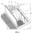
- the panels (3) which constitute the protection barrier (2) are lowered along the rails (4) until being arranged vertically inside the substation, which position is achieved when the upper channels (9) of the panels (3) abut against the aforementioned rails (4). In this position, the panels (3) extend until reaching near the bed of the electrical equipment on the ground (12), the protection barrier (2) working from this moment as a baffle, conducting the cooling air toward the low parts of the electrical equipment and thereby improving the ventilation system, such as is shown in figures 2 and 4 .
Description
- The present invention relates to a transformer substation which incorporates a protection barrier which, besides guaranteeing the safety of the passers-by, on opening the access to the interior thereof, allows optimal cooling to be achieved of the equipment housed in its interior, when the centre is in service and access thereto is closed.
- It is an object of the invention that the safety barrier acts as a baffle for the conduction of air toward the low parts of the electrical equipment, thereby improving the ventilation system thereof.
- Transformer substations are intended to house in their interior all types of electrical gear such as transformers, medium and low voltage switchboards, etc., and according to their emplacement can be either on the surface or underground, with the special particularity that the underground substations improve the visual appearance of their surroundings and in turn allow freeing of urban space.
- The underground transformer substations are generally constituted by means of a chamber of appropriate dimensions that can be of civil work or prefabricated in nature, both of concrete and of other materials, which is below ground and in the interior of which is installed the different electrical equipment. This chamber is finished on top with a cover or roof which constitutes the surface on which it is possible to walk and which is closed in a fixed manner to the chamber to guarantee a good seal against dampness and water. To be able to carry out the maintenance tasks, said transformer substations have to allow access to their interior, having for this an access hatch for the operatives.
- These access hatches, in their open position, have to guarantee the safety of passers-by from possibly falling accidentally into the interior of the transformer substation, to which end different systems are used. One of the most common systems is for example that represented in the utility model
ES 1049753 ES 2181581 ES 2157770 - The previous solution implies a complicated design of the protection handrail, due to the numerous pieces and folding mechanisms which are used, increasing thereby its corresponding cost.
- In addition, the hot air generated by the transformer losses rises and is evacuated through the corresponding air vent of the transformer substation, by chimney effect. To optimise this ventilation, baffle elements are generally used, like for example those described in the patents
ES 2181581 ES 2157770 - The patents
EP-1.435.681 ,EP-0.499.592 ,DE-1936738 and the Utility ModelDE-7223445 , describe underground transformer centres, which are not provided with panels having two operative positions to act as a protection and also as deflector for the cooling air. - The substation of the invention incorporates a protection barrier which, besides guaranteeing the safety of passers-by in the open position of the access to the interior of the transformer substation, constitutes an interior baffle which guarantees an adequate cooling of the electrical equipment, when the access to the interior of the transformer substation is closed, without this signifying an additional need for space for the location or operation of the aforesaid baffle.
- The protection barrier is constituted by one or several panels which, in the open position of the access hatch, rise up on one or several sides of the access to the substation, by means of some guide elements, and which are immobilized in their position of maximum elevation, thereby impeding the displacement of the barrier until the manoeuvring or maintenance operations finish, guaranteeing the safety of passers-by, using a solution with a simple design and reducing its corresponding cost.
- In the operational position of the substation, with the hatch closed, the barrier is arranged in a vertical position, inside the substation, extending until near the bed of the electrical equipment on the ground and working as from this moment like a baffle, allowing an appropriate conduction of air toward the low parts of the electrical equipment. With this configuration unusable spaces are avoided inside the transformer substation since the protection barrier, which acts as a baffle, is mounted in the access area to the substation but is slid upward in the open position to leave free space during the maintenance operations of the substation.
- The protection barrier comprises some means of manipulation which facilitate the task of both raising and lowering the same.
- To complete the description that is being made and with the object of assisting in a better understanding of the characteristics of the invention, this description is accompanied with, as an integral part thereof, a set of drawings wherein by way of illustration and not restrictively, the following has been represented:
-
Figure 1 .. It represents a view in perspective of the operator access open with the protection barrier raised. -
Figure 2 .. It represents a view in perspective of the operator access open with the protection barrier lowered, working in this case as a baffle. -
Figure 3 .. It shows a view in perspective of the access from a position opposite to that offigure 2 . -
Figure 4 .. It shows a view in side elevation and in cross-section of a transformer substation wherein the baffle is shown in its working position. - Next, by way of explanation and not restrictively, an embodiment of the transformer substation is presented and of its protection barrier, in both the open position of the hatch that gives access to the interior of the substation and in the closed position thereof in which the barrier acts as a baffle for the conduction of air cooling the transformer substation.
- The access for the operatives to the interior of the transformer substation is made through a hatch (10), which is opened and remains open, by immobilizing said hatch (10) by means of the locking mechanism (11), such as is shown in
figure 3 , avoiding thereby an accidental closure thereof while the maintenance and/or manoeuvring tasks are going on. - To avoid accidents, the substation object of the invention, such as is shown in
figure 1 , incorporates a protection barrier (2), on the opposite side to the hatch (10) which can be constituted by a single piece or by independent panels (3), of sheet metal or other materials which, in the moment of opening the access (1) slide upward to emerge on the exterior and constitute a means of safeguarding the passers-by. The raising of the protection barrier (2) is carried out with the collaboration of some means of manipulation, such as horizontal channels (9), and through some guide elements, such as rails (4) fixed to the access frame (1), until some locking mechanism elements, such as pins or bolts (8), automatically engage in their respective anchor sockets (13), thereby immobilizing the protection barrier (2) in its raised position and impeding the accidental displacement thereof which could leave the access without protection. - The horizontal channels (9) can be mounted on the upper and lower part of the panels (3), to facilitate their elevation or descent, acting also as butts limiting the operative positions of the barrier.
- This protection barrier (2) incorporates some flanges (5) which close the free spaces both between the steps (7) and the barrier (2) and between the lateral protection fence (6) and the barrier (2), thereby improving safety for the passers-by.
- When the maintenance tasks have finished, the panels (3) which constitute the protection barrier (2) are lowered along the rails (4) until being arranged vertically inside the substation, which position is achieved when the upper channels (9) of the panels (3) abut against the aforementioned rails (4). In this position, the panels (3) extend until reaching near the bed of the electrical equipment on the ground (12), the protection barrier (2) working from this moment as a baffle, conducting the cooling air toward the low parts of the electrical equipment and thereby improving the ventilation system, such as is shown in
figures 2 and4 .
Claims (9)
- Underground transformer substation comprising at least an access (1) to the interior of the substation characterised in that said access (1) incorporates a protection barrier (2) constitued by one or several panels (3) having two different operative positions, one in which said one or several panels (3) are arranged externally to the substation, acting as a means of safeguarding the passers-by and a second position, in which said one or several panels (3) are completely inside the substation, acting as a baffle for directing the air cooling the transformer substation in the in-service position thereof.
- Underground transformer substation according to claim 1, characterised in that the panel or panels (3) are arranged on one or several sides of the access opening to the substation.
- Underground transformer substation according to claim 1, characterised in that the panel or panels (3) can slide in the vertical direction.
- Underground transformer substation according to claim 3, characterised in that the panel or panels (3) are displaced on rails (4) mounted on the frame of the access opening to the substation.
- Underground transformer substation according to claim 3, characterised in that the panel or panels (3) comprise some horizontal channels (9) which facilitate the work of displacing the panels (3) and act as a butt limiting their operative positions.
- Underground transformer substation according to claim 1, characterised in that the panel or panels (3), in their lowermost position, reach near to the bed of the electrical equipment on the ground (12).
- Underground transformer substation according to claim 1, characterised in that the panel or panels (3) have a locking mechanism (8) for the purpose of preventing the displacement of the panels (3) in the open position of the access (1).
- Underground transformer substation according to claim 7, characterised in that the locking mechanisms (8) are bolts which in the moment of opening the access (1), when the panels (3) are raised, automatically engage in their respective anchor sockets, thereby impeding the displacement of the panels (3).
- Underground transformer substation according to claim 1, characterised in that the panel or panels (3) incorporate on their ends some flanges (5) which in the open position of the access (1) close the free space both between the barrier (2) and the stairway (7) and between said barrier (2) and the lateral protection fence (6).
Priority Applications (2)
| Application Number | Priority Date | Filing Date | Title |
|---|---|---|---|
| ES04380153T ES2396910T3 (en) | 2004-07-19 | 2004-07-19 | Underground transformation substation with barrier-deflector device |
| EP20040380153 EP1619323B1 (en) | 2004-07-19 | 2004-07-19 | Underground transformer substation with baffle-barrier device |
Applications Claiming Priority (1)
| Application Number | Priority Date | Filing Date | Title |
|---|---|---|---|
| EP20040380153 EP1619323B1 (en) | 2004-07-19 | 2004-07-19 | Underground transformer substation with baffle-barrier device |
Publications (2)
| Publication Number | Publication Date |
|---|---|
| EP1619323A1 EP1619323A1 (en) | 2006-01-25 |
| EP1619323B1 true EP1619323B1 (en) | 2012-07-11 |
Family
ID=34931853
Family Applications (1)
| Application Number | Title | Priority Date | Filing Date |
|---|---|---|---|
| EP20040380153 Not-in-force EP1619323B1 (en) | 2004-07-19 | 2004-07-19 | Underground transformer substation with baffle-barrier device |
Country Status (2)
| Country | Link |
|---|---|
| EP (1) | EP1619323B1 (en) |
| ES (1) | ES2396910T3 (en) |
Families Citing this family (4)
| Publication number | Priority date | Publication date | Assignee | Title |
|---|---|---|---|---|
| ES2157770B1 (en) * | 1999-03-24 | 2002-03-01 | Schneider Electric Espana Sa | "TRANSFORMATION CENTER FOR ELECTRICAL NETWORKS". |
| ES2321258B1 (en) * | 2006-12-22 | 2010-03-04 | Prefabricados Uniblok S.A. | OPERATOR ACCESS DOOR FOR UNDERGROUND BUILDINGS. |
| ES2351745B1 (en) * | 2008-07-24 | 2011-12-05 | Antonio Fernandez Del Hoyo | ENVELOPE WITH ENTIRE STRUCTURE OF CONCRETE CONCRETE FOR UNDERGROUND TRANSFORMATION CENTERS. |
| CN110459978A (en) * | 2019-08-23 | 2019-11-15 | 华翔翔能电气股份有限公司 | A kind of fixed device of the body structure of full burying-terra transformer substation |
Family Cites Families (6)
| Publication number | Priority date | Publication date | Assignee | Title |
|---|---|---|---|---|
| DE1936738A1 (en) * | 1969-07-18 | 1971-02-04 | Elek Zitaets Actien Ges Vorm W | Transformer station |
| DE7223445U (en) * | 1972-06-23 | 1976-11-18 | Fa. Gerd Doeker, 4420 Coesfeld | Switchgear |
| IT1252940B (en) * | 1991-02-14 | 1995-07-05 | Cosmo Seri | UNDERGROUND ELECTRIC TRANSFORMATION CABIN, CONSTITUTED BY TWO CELLS CONTAINED ONE WITHIN THE OTHER. |
| IT1286390B1 (en) * | 1996-11-20 | 1998-07-08 | Nr Dev Ltd | CONTAINER FOR THE INSTALLATION OF EQUIPMENT, IN PARTICULAR ELECTRONIC EQUIPMENT, IN UNDERGROUND POSITION |
| DE19727438C1 (en) * | 1997-06-27 | 1998-12-10 | Martin Lesti | Built in fan element for ventilation opening in building wall |
| ES2229873B1 (en) * | 2002-12-26 | 2006-05-16 | Grupo Ormazabal, S.A. | TRANSFORMATION CENTER FOR UNDERGROUND NETWORKS. |
-
2004
- 2004-07-19 EP EP20040380153 patent/EP1619323B1/en not_active Not-in-force
- 2004-07-19 ES ES04380153T patent/ES2396910T3/en active Active
Also Published As
| Publication number | Publication date |
|---|---|
| ES2396910T3 (en) | 2013-03-01 |
| EP1619323A1 (en) | 2006-01-25 |
Similar Documents
| Publication | Publication Date | Title |
|---|---|---|
| US9382099B2 (en) | Motorized height access device for tower cranes | |
| EP3052732B1 (en) | Flood protection for underground air vents | |
| US20180354351A1 (en) | Construction machine with operating platform and access control | |
| WO2012126619A1 (en) | Elevator having a minimal shaft top height and a permanent protective space | |
| KR20110134256A (en) | Paneling of a nacelle of a wind energy installation | |
| EP2570653B1 (en) | Convertible wind turbine nacelle cover | |
| EP1619323B1 (en) | Underground transformer substation with baffle-barrier device | |
| EP0878808A2 (en) | Electric transformer station | |
| ITBA20130067A1 (en) | LIFTING AND HORIZONTAL TRAVELING MECHANISM OF LIDING COVERS OR WHEELS | |
| DE19829156A1 (en) | Underground store for esp. rubbish bins consists of storage cell for bins, lowered into underground chamber by lifting device | |
| KR102362221B1 (en) | Ventilation combined use emergency exit for utility pipe conduit with upward opening and closing doors | |
| CN217106039U (en) | On-site industrial construction integrated platform for construction engineering | |
| CN109267910A (en) | Double-deck multipurpose venting of dust explosion vertical hinged door device | |
| GB2521763A (en) | Movable workshop | |
| KR200418432Y1 (en) | Distributing board door having a visor | |
| CN205805011U (en) | New type of safe preventer cover plate | |
| CN218560783U (en) | Linkage protection plate safety device of flap gate type construction elevator | |
| WO2004046469A1 (en) | Access covers | |
| CN220133539U (en) | Discharging platform | |
| CN216613641U (en) | Lifting device and tower drum | |
| EP1500757B1 (en) | Prefabricated construction with passable cover for industrial applications | |
| US20230349146A1 (en) | Housing including roof/cover adapted with retractable panels in hinged connection to outwardly movable side walls | |
| CN218664858U (en) | Construction elevator protector | |
| KR200387553Y1 (en) | The moving power receiving and transforming device | |
| CN106285451B (en) | A kind of factory building folded outboard formula cat ladder |
Legal Events
| Date | Code | Title | Description |
|---|---|---|---|
| PUAI | Public reference made under article 153(3) epc to a published international application that has entered the european phase |
Free format text: ORIGINAL CODE: 0009012 |
|
| AK | Designated contracting states |
Kind code of ref document: A1 Designated state(s): AT BE BG CH CY CZ DE DK EE ES FI FR GB GR HU IE IT LI LU MC NL PL PT RO SE SI SK TR |
|
| AX | Request for extension of the european patent |
Extension state: AL HR LT LV MK |
|
| 17P | Request for examination filed |
Effective date: 20060724 |
|
| AKX | Designation fees paid |
Designated state(s): AT BE BG CH CY CZ DE DK EE ES FI FR GB GR HU IE IT LI LU MC NL PL PT RO SE SI SK TR |
|
| RAP1 | Party data changed (applicant data changed or rights of an application transferred) |
Owner name: PREFABRICADOS UNIBLOK, S.A.U. |
|
| RAP1 | Party data changed (applicant data changed or rights of an application transferred) |
Owner name: PREFABRICADOS UNIBLOK,S.L.U. |
|
| GRAP | Despatch of communication of intention to grant a patent |
Free format text: ORIGINAL CODE: EPIDOSNIGR1 |
|
| GRAS | Grant fee paid |
Free format text: ORIGINAL CODE: EPIDOSNIGR3 |
|
| GRAA | (expected) grant |
Free format text: ORIGINAL CODE: 0009210 |
|
| AK | Designated contracting states |
Kind code of ref document: B1 Designated state(s): AT BE BG CH CY CZ DE DK EE ES FI FR GB GR HU IE IT LI LU MC NL PL PT RO SE SI SK TR |
|
| REG | Reference to a national code |
Ref country code: GB Ref legal event code: FG4D |
|
| REG | Reference to a national code |
Ref country code: CH Ref legal event code: EP |
|
| REG | Reference to a national code |
Ref country code: AT Ref legal event code: REF Ref document number: 566231 Country of ref document: AT Kind code of ref document: T Effective date: 20120715 |
|
| REG | Reference to a national code |
Ref country code: IE Ref legal event code: FG4D |
|
| REG | Reference to a national code |
Ref country code: DE Ref legal event code: R096 Ref document number: 602004038492 Country of ref document: DE Effective date: 20120906 |
|
| REG | Reference to a national code |
Ref country code: NL Ref legal event code: VDEP Effective date: 20120711 |
|
| REG | Reference to a national code |
Ref country code: AT Ref legal event code: MK05 Ref document number: 566231 Country of ref document: AT Kind code of ref document: T Effective date: 20120711 |
|
| PG25 | Lapsed in a contracting state [announced via postgrant information from national office to epo] |
Ref country code: BE Free format text: LAPSE BECAUSE OF FAILURE TO SUBMIT A TRANSLATION OF THE DESCRIPTION OR TO PAY THE FEE WITHIN THE PRESCRIBED TIME-LIMIT Effective date: 20120711 Ref country code: CY Free format text: LAPSE BECAUSE OF FAILURE TO SUBMIT A TRANSLATION OF THE DESCRIPTION OR TO PAY THE FEE WITHIN THE PRESCRIBED TIME-LIMIT Effective date: 20120711 Ref country code: AT Free format text: LAPSE BECAUSE OF FAILURE TO SUBMIT A TRANSLATION OF THE DESCRIPTION OR TO PAY THE FEE WITHIN THE PRESCRIBED TIME-LIMIT Effective date: 20120711 Ref country code: FI Free format text: LAPSE BECAUSE OF FAILURE TO SUBMIT A TRANSLATION OF THE DESCRIPTION OR TO PAY THE FEE WITHIN THE PRESCRIBED TIME-LIMIT Effective date: 20120711 |
|
| PG25 | Lapsed in a contracting state [announced via postgrant information from national office to epo] |
Ref country code: SE Free format text: LAPSE BECAUSE OF FAILURE TO SUBMIT A TRANSLATION OF THE DESCRIPTION OR TO PAY THE FEE WITHIN THE PRESCRIBED TIME-LIMIT Effective date: 20120711 Ref country code: SI Free format text: LAPSE BECAUSE OF FAILURE TO SUBMIT A TRANSLATION OF THE DESCRIPTION OR TO PAY THE FEE WITHIN THE PRESCRIBED TIME-LIMIT Effective date: 20120711 Ref country code: GR Free format text: LAPSE BECAUSE OF FAILURE TO SUBMIT A TRANSLATION OF THE DESCRIPTION OR TO PAY THE FEE WITHIN THE PRESCRIBED TIME-LIMIT Effective date: 20121012 Ref country code: PT Free format text: LAPSE BECAUSE OF FAILURE TO SUBMIT A TRANSLATION OF THE DESCRIPTION OR TO PAY THE FEE WITHIN THE PRESCRIBED TIME-LIMIT Effective date: 20121112 Ref country code: MC Free format text: LAPSE BECAUSE OF NON-PAYMENT OF DUE FEES Effective date: 20120731 Ref country code: PL Free format text: LAPSE BECAUSE OF FAILURE TO SUBMIT A TRANSLATION OF THE DESCRIPTION OR TO PAY THE FEE WITHIN THE PRESCRIBED TIME-LIMIT Effective date: 20120711 |
|
| REG | Reference to a national code |
Ref country code: CH Ref legal event code: PL Ref country code: ES Ref legal event code: PC2A Owner name: ORMAZABAL Y CIA S.L.U. Effective date: 20130218 |
|
| REG | Reference to a national code |
Ref country code: ES Ref legal event code: FG2A Ref document number: 2396910 Country of ref document: ES Kind code of ref document: T3 Effective date: 20130301 |
|
| PG25 | Lapsed in a contracting state [announced via postgrant information from national office to epo] |
Ref country code: NL Free format text: LAPSE BECAUSE OF FAILURE TO SUBMIT A TRANSLATION OF THE DESCRIPTION OR TO PAY THE FEE WITHIN THE PRESCRIBED TIME-LIMIT Effective date: 20120711 |
|
| PG25 | Lapsed in a contracting state [announced via postgrant information from national office to epo] |
Ref country code: CZ Free format text: LAPSE BECAUSE OF FAILURE TO SUBMIT A TRANSLATION OF THE DESCRIPTION OR TO PAY THE FEE WITHIN THE PRESCRIBED TIME-LIMIT Effective date: 20120711 Ref country code: LI Free format text: LAPSE BECAUSE OF NON-PAYMENT OF DUE FEES Effective date: 20120731 Ref country code: RO Free format text: LAPSE BECAUSE OF FAILURE TO SUBMIT A TRANSLATION OF THE DESCRIPTION OR TO PAY THE FEE WITHIN THE PRESCRIBED TIME-LIMIT Effective date: 20120711 Ref country code: DK Free format text: LAPSE BECAUSE OF FAILURE TO SUBMIT A TRANSLATION OF THE DESCRIPTION OR TO PAY THE FEE WITHIN THE PRESCRIBED TIME-LIMIT Effective date: 20120711 Ref country code: DE Free format text: LAPSE BECAUSE OF NON-PAYMENT OF DUE FEES Effective date: 20130201 Ref country code: EE Free format text: LAPSE BECAUSE OF FAILURE TO SUBMIT A TRANSLATION OF THE DESCRIPTION OR TO PAY THE FEE WITHIN THE PRESCRIBED TIME-LIMIT Effective date: 20120711 Ref country code: CH Free format text: LAPSE BECAUSE OF NON-PAYMENT OF DUE FEES Effective date: 20120731 |
|
| REG | Reference to a national code |
Ref country code: IE Ref legal event code: MM4A |
|
| REG | Reference to a national code |
Ref country code: DE Ref legal event code: R119 Ref document number: 602004038492 Country of ref document: DE Effective date: 20130201 |
|
| PLBE | No opposition filed within time limit |
Free format text: ORIGINAL CODE: 0009261 |
|
| STAA | Information on the status of an ep patent application or granted ep patent |
Free format text: STATUS: NO OPPOSITION FILED WITHIN TIME LIMIT |
|
| PG25 | Lapsed in a contracting state [announced via postgrant information from national office to epo] |
Ref country code: SK Free format text: LAPSE BECAUSE OF FAILURE TO SUBMIT A TRANSLATION OF THE DESCRIPTION OR TO PAY THE FEE WITHIN THE PRESCRIBED TIME-LIMIT Effective date: 20120711 Ref country code: IT Free format text: LAPSE BECAUSE OF FAILURE TO SUBMIT A TRANSLATION OF THE DESCRIPTION OR TO PAY THE FEE WITHIN THE PRESCRIBED TIME-LIMIT Effective date: 20120711 |
|
| REG | Reference to a national code |
Ref country code: FR Ref legal event code: ST Effective date: 20130426 |
|
| 26N | No opposition filed |
Effective date: 20130412 |
|
| GBPC | Gb: european patent ceased through non-payment of renewal fee |
Effective date: 20121011 |
|
| PG25 | Lapsed in a contracting state [announced via postgrant information from national office to epo] |
Ref country code: BG Free format text: LAPSE BECAUSE OF FAILURE TO SUBMIT A TRANSLATION OF THE DESCRIPTION OR TO PAY THE FEE WITHIN THE PRESCRIBED TIME-LIMIT Effective date: 20121011 Ref country code: IE Free format text: LAPSE BECAUSE OF NON-PAYMENT OF DUE FEES Effective date: 20120719 Ref country code: GB Free format text: LAPSE BECAUSE OF NON-PAYMENT OF DUE FEES Effective date: 20121011 |
|
| PG25 | Lapsed in a contracting state [announced via postgrant information from national office to epo] |
Ref country code: FR Free format text: LAPSE BECAUSE OF NON-PAYMENT OF DUE FEES Effective date: 20120911 |
|
| PG25 | Lapsed in a contracting state [announced via postgrant information from national office to epo] |
Ref country code: TR Free format text: LAPSE BECAUSE OF FAILURE TO SUBMIT A TRANSLATION OF THE DESCRIPTION OR TO PAY THE FEE WITHIN THE PRESCRIBED TIME-LIMIT Effective date: 20120711 |
|
| PG25 | Lapsed in a contracting state [announced via postgrant information from national office to epo] |
Ref country code: LU Free format text: LAPSE BECAUSE OF NON-PAYMENT OF DUE FEES Effective date: 20120719 |
|
| PG25 | Lapsed in a contracting state [announced via postgrant information from national office to epo] |
Ref country code: HU Free format text: LAPSE BECAUSE OF FAILURE TO SUBMIT A TRANSLATION OF THE DESCRIPTION OR TO PAY THE FEE WITHIN THE PRESCRIBED TIME-LIMIT Effective date: 20040719 |
|
| PGFP | Annual fee paid to national office [announced via postgrant information from national office to epo] |
Ref country code: ES Payment date: 20160622 Year of fee payment: 13 |
|
| REG | Reference to a national code |
Ref country code: ES Ref legal event code: FD2A Effective date: 20181105 |
|
| PG25 | Lapsed in a contracting state [announced via postgrant information from national office to epo] |
Ref country code: ES Free format text: LAPSE BECAUSE OF NON-PAYMENT OF DUE FEES Effective date: 20170720 |