EP1619297A2 - Blende eines Stoffauflaufs - Google Patents
Blende eines Stoffauflaufs Download PDFInfo
- Publication number
- EP1619297A2 EP1619297A2 EP05104970A EP05104970A EP1619297A2 EP 1619297 A2 EP1619297 A2 EP 1619297A2 EP 05104970 A EP05104970 A EP 05104970A EP 05104970 A EP05104970 A EP 05104970A EP 1619297 A2 EP1619297 A2 EP 1619297A2
- Authority
- EP
- European Patent Office
- Prior art keywords
- hold
- panel
- aperture
- diaphragm
- headbox
- Prior art date
- Legal status (The legal status is an assumption and is not a legal conclusion. Google has not performed a legal analysis and makes no representation as to the accuracy of the status listed.)
- Granted
Links
Images

Classifications
-
- D—TEXTILES; PAPER
- D21—PAPER-MAKING; PRODUCTION OF CELLULOSE
- D21F—PAPER-MAKING MACHINES; METHODS OF PRODUCING PAPER THEREON
- D21F1/00—Wet end of machines for making continuous webs of paper
- D21F1/02—Head boxes of Fourdrinier machines
- D21F1/028—Details of the nozzle section
-
- D—TEXTILES; PAPER
- D21—PAPER-MAKING; PRODUCTION OF CELLULOSE
- D21F—PAPER-MAKING MACHINES; METHODS OF PRODUCING PAPER THEREON
- D21F1/00—Wet end of machines for making continuous webs of paper
- D21F1/02—Head boxes of Fourdrinier machines
Definitions
- the invention relates to an orifice for a headbox of a at least one fibrous suspension a fibrous web producing machine, in particular a paper or board machine, with a diaphragm support surface by means of several each holding force generating hold-down in a support area at an outer and end lip contact surface of a lip of the headbox is appropriate.
- the diaphragm has a flat diaphragm support surface and it is fixedly mounted or displaceable on a flat lip support surface by suitable hold-down elements.
- the hold-down elements are preferably designed as screw elements, spring elements and / or lever elements.
- the projecting into the nozzle space of the headbox part of the diaphragm is acted upon by the prevailing at this point nozzle pressure during operation of the headbox, wherein the nozzle pressure increases quadratically to the speed of the jet flowing through the pulp suspension.
- the resulting force attempts to lift the bezel off its seat.
- the said hold-down elements must absorb at least this resultant force.
- the hold-down elements are usually arranged, in particular due to prevailing reasons of space, with a distance upstream to the resulting force and over the diaphragm.
- the resulting gap between the diaphragm and lip resulting from the lifting of the diaphragm fibers can pinch and lead to webbing.
- the lifting of the aperture over the iris or machine width across is imperatively not the same size, so that an uneven lifting of the aperture leads to non-uniform changes of the nozzle outlet gap.
- the degree of bending of the diaphragm is determined by the magnitude of the pressure force on the one hand and by the lever ratios of the holddown and the diaphragm thickness on the other.
- a gap-free resting of the aperture would be achieved in the known embodiments only by an arrangement of hold-down elements in direct extension of the compressive force and by a large-sized, yes oversized aperture with a preferably infinite aperture thickness.
- a short free jet length of the headbox jet is advantageous for a good quality of the fibrous web.
- the prevailing at the beginning of the free jet turbulence structure is also an ideal condition for a good formation of the fibrous web.
- this goal is limited attainable from said requirements.
- twin-wire formers in the design of gap formers the free jet lengths are also substantially dependent on the machine width. For example, wide machines require larger roller diameters due to the requirement for low deflections and favorable vibration behavior of the rollers.
- the rolls may be, for example, a forming roll and a breast roll in a roll-blade former, and two breast rolls in a bi-roll roll former.
- the larger roll diameters reduce the space in the jet injection area and force a larger free jet length of the headbox jet.
- the invention has for its object to provide an improved panel for a headbox of the type mentioned in the use of short free jet lengths are also possible on headboxes for Doppelsiebformer.
- the headboxes should also be particularly suitable for fast and / or wide machines.
- At least one of the two surfaces is designed such that the aperture in the untensioned state in the region of the support region has a front and a rear support area and a middle non-contact area, wherein the hold-down force of the individual hold-down element acts in brinauflage Symposium.
- This embodiment provides the advantage that the diaphragm can be deformed controlled during operation of the headbox due to acting compressive forces.
- the size of the present in the unstressed state average non-contact area is reduced to a minimum and the diaphragm support surface is as far as possible or completely on the lip support surface.
- At least one of the two surfaces has a convex contour, at least in the central support region, wherein the convexity preferably corresponds at least to the bending line of the diaphragm under the influence of compressive force and hold-down force.
- At least one of the two surfaces has a hinterstochene contour at least in the central support area, wherein the undercut has a depth which preferably corresponds to at least the bending line of the diaphragm under the influence of compressive force and hold-down force.
- the geometries convexity and depth of the undercut can be chosen without hesitation larger than computationally necessary. Of importance is only that they at least correspond to the mentioned bending line.
- the diaphragm is preferably resiliently biased with the hold-down elements in the region of the non-contact region, so that the distance between the two surfaces in the non-contact region becomes smaller.
- the diaphragm can also be resiliently biased with the hold-down elements such that the distance between the two surfaces in the non-contact region is reduced very small, preferably to zero. This results in a defined and constant bias across the width of the aperture.
- the biasing force acting on the panel is preferably greater than the sum of the operating forces acting during operation of the headbox.
- the hold-down elements are preferably designed as plate spring packets, which are arranged in respective recesses in the panel.
- the hold-down elements are thus integrated into the overall height of the panel and they no longer sit above the panel when generating increased heights.
- the respective disc springs of a plate spring package can be arranged in a cup wheel and be biased with a collar screw or with a collar nut and a stud.
- the diaphragm has a desired total height ⁇ 25 mm, preferably ⁇ 20 mm.
- the dimensioning of the overall height is based on the maximum prevailing bending stress and not on the bending deformation of the diaphragm.
- the cavity in the middle area may be filled with a softer and possibly less expensive material that can be compressed when biasing the panel.
- the diaphragm preferably has a diaphragm width ⁇ 5,000 mm with a free jet length ⁇ 250 mm and preferably a diaphragm width ⁇ 8,000 mm with a free jet length ⁇ 350 mm. These properties also meet the latest requirements in the field of twin wire formers, in particular gap formers.
- FIG. 1 shows a schematic longitudinal section of a known panel 1 for a headbox 2, not shown in detail of a at least one pulp suspension 3 a fibrous web producing machine, in particular a paper or board machine.
- the upper side of the headbox 1 mounted aperture 1 has on its underside a flat diaphragm support surface 4, by means of several each holding down force F N (arrow) generating and preferably arranged in a row hold-down elements 5 (dashed line) in a support area 6 at an outer, end and level lip support surface 8 a lip 7 (upper lip) of the headbox 2 is fixed or slidably mounted.
- F N holding down force
- F N generating and preferably arranged in a row hold-down elements 5 (dashed line) in a support area 6 at an outer, end and level lip support surface 8 a lip 7 (upper lip) of the headbox 2 is fixed or slidably mounted.
- the panel can also be attached on the underside to a lip (lower lip) of the headbox.
- the hold-down elements 5 are preferably designed as screw elements, spring elements and / or lever elements.
- the projecting into the nozzle chamber 9 of the headbox 2 and a reduced peak angle part 10 (front panel) of the diaphragm 1 is acted upon by the prevailing at this point nozzle pressure F D (arrow) during operation of the headbox 2, wherein the nozzle pressure F D (arrow ) squared to the speed v (arrow) of the jet 9 flowing through the pulp suspension 3 increases.
- the resulting force tries to lift off the panel 1 from its support 6.
- the panel 1 is thus subjected to a classic beam bending, which can lead to a lift of the front panel 10 from the support 6 in generating a gap 11 generally at too small a dimensioning of the panel 1 and the hold-down elements.
- a classic beam bending can lead to a lift of the front panel 10 from the support 6 in generating a gap 11 generally at too small a dimensioning of the panel 1 and the hold-down elements.
- the resulting gap through the aperture 1 gap 11 between the aperture 1 and lip 7 fibers can pinch and lead to webbing.
- the lifting of the aperture 1 across the aperture or machine width away is not necessarily the same size, so that an uneven lifting of the aperture 1 leads to non-uniform changes of the nozzle outlet gap 12.
- the supernatant of the diaphragm front part 10 must be selected larger and the junction to be shifted upstream. For such a case, the bend increases approximately 10 times when the gap 11 is formed.
- FIGS. 2A to 2D show various embodiments of panels 1 according to the invention for one headbox 2 in schematic longitudinal sectional views.
- All four figures have in common that at least one of the two surfaces 4, 8 is designed such that the respective panel 1 in the untensioned state in the region of the support area 6 has a front and a rear support area 13, 14 and a central non-support area 15, wherein the hold-down force F N (arrow) of the individual hold-down element 5 in the non-contact area 15 acts.
- FIGS. 2A and 2B show two embodiments, wherein at least one of the two surfaces 4, 8 has a convex contour K at least in the central support region 15.
- this is the lip support surface 8 of the lip 7
- this is the diaphragm support surface 1 of the diaphragm 1.
- the convexity of the respective contour K corresponds at least to the bending line of the diaphragm 1 under the influence of pressure force F D (arrow) and hold-down force F N (Arrow).
- FIGS. 2C and 2D in turn show two embodiments, wherein at least one of the two surfaces 4, 8 has a back-punched contour H at least in the central support region 15.
- this is the lip support surface 8 of the lip 7
- this is the diaphragm support surface 4 of the diaphragm 1.
- the undercut of the contour H has a depth T which is at least the bending line of the diaphragm 1 under the influence of pressure force F D (arrow ) and hold-down force F N (arrow).
- the panel 1 is resiliently biased in the embodiments of Figures 2A to 2D with hold-down elements 5 in the region of the respective non-contact area 15. It is biased so resiliently with the hold-down elements 5 that the distance A of the two surfaces 4, 8 in the non-contact area 15 is very small, preferably reduced to zero. In this way, a defined and constant bias across the width B (arrow) of the diaphragm 1, which has a value ⁇ 5,000 mm, preferably ⁇ 8,000 mm, achieved.
- the acting biasing force F N (arrow) is commonly greater than the sum of the forces acting during operation of the headbox 2 operating forces.
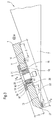
- FIG. 3 shows a further embodiment of an inventive panel 1 for a headbox 2 in a schematic longitudinal section.
- the turn on the top of the headbox 2 mounted aperture 1 has the underside in the middle support area 15 an aperture support surface 4 with a Schustochenen contour H.
- the undercut of the contour H has a depth T which corresponds at least to the bending line of the panel 1 under the influence of compressive force F D (arrow) and hold-down force F N (arrow).
- the hold-down element 5 is designed as a plate spring package 16, which is arranged in a recess 17 in the panel 1.
- the disc springs 18 of the disc spring assembly 16 are arranged in a cup wheel 19 and biased with a collar nut 20 and a stud 21.
- the panel 1 has an overall height G ⁇ 25 mm, preferably ⁇ 20 mm, with a panel width B (arrow) ⁇ 5,000 mm, preferably ⁇ 8,000 mm.
- the cavity 25 in the middle non-support area 15 is filled with a soft material 26, such as sponge rubber and the like, which can be compressed during biasing of the panel 1.
- a soft material 26 such as sponge rubber and the like
- the two bearing areas 13, 14 have a respective length C, D, which is smaller than 5 mm if possible. Furthermore, the tip 27 of the lip 7 has a weakening 22 shown in dashed lines. This creates downstream a pressing point, which prevents the application of the tip 27 to the panel 1 due to the nozzle pressure F D (arrows) that a gap.
- the assembly of the panel 1 can be done in many ways.
- the flanged nut 20 can be tightened against the lip 7 in a stop, torque-controlled or gauge-controlled manner.
- the type of mounting of the panel 1 is so varied and it will be chosen depending on the application of a number of many known solutions.
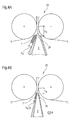
- FIGs 4A and 4B show two installation situations of panels 1 for each headbox 2 in schematic side views.
- the respective headbox 2 opens into an initially indicated twin-wire former 23 of known construction, which has the same geometric properties in both embodiments.
- FIG. 4A shows an installation situation of a known panel 1
- FIG. 4B shows an installation situation of the panel 1 according to the invention.
- the height h B of the known diaphragm 1 is significantly greater than the height h E of the diaphragm 1 according to the invention, the height h E corresponding to the total height G, which assumes a value ⁇ 25 mm, preferably ⁇ 20 mm ,
- a headbox 2 with a known aperture 1 necessarily larger free jet length L B of the headbox jet 24 with respect to the free jet length L E of the headbox jet 24 with inventive aperture 1 on.
- the diaphragm 1 according to the invention preferably has a free-jet length L E ⁇ 250 mm with an aperture width B (arrow) ⁇ 5,000 mm and a free-jet length L E ⁇ 350 mm with an aperture width B (arrow) ⁇ 8,000 mm.
- the invention provides an improved aperture for a headbox of the type mentioned, in the use of short free jet lengths are also possible on headboxes for Doppelsiebformer.
- the headboxes are also particularly suitable for fast and / or wide machines.
Landscapes
- Paper (AREA)
- Magnetic Resonance Imaging Apparatus (AREA)
- Nonwoven Fabrics (AREA)
- Fuel Cell (AREA)
- Holding Or Fastening Of Disk On Rotational Shaft (AREA)
- Bolts, Nuts, And Washers (AREA)
Abstract
Description
- Die Erfindung betrifft eine Blende für einen Stoffauflauf einer aus zumindest einer Faserstoffsuspension eine Faserstoffbahn herstellenden Maschine, insbesondere einer Papier- oder Kartonmaschine, mit einer Blendenauflagefläche, die mittels mehrerer jeweils eine Niederhaltekraft erzeugender Niederhalteelemente in einem Auflagebereich an einer äußeren und endseitigen Lippenauflagefläche einer Lippe des Stoffauflaufs angebracht ist.
- Eine derartige Blende ist beispielsweise aus der deutschen Offenlegungsschrift DE 42 39 646 A1 bekannt. Die Blende weist eine ebene Blendenauflagefläche auf und sie ist auf einer ebenen Lippenauflagefläche durch geeignete Niederhalteelemente feststehend oder verschiebbar gelagert. Die Niederhalteelemente sind vorzugsweise als Schraubenelemente, Federelemente und/oder Hebelelemente ausgeführt. Der in den Düsenraum des Stoffauflaufs ragende Teil der Blende wird mit dem an dieser Stelle herrschenden Düsendruck während des Betriebs des Stoffauflaufs beaufschlagt, wobei der Düsendruck quadratisch zur Geschwindigkeit der die Düse durchströmenden Faserstoffsuspension steigt. Die daraus resultierende Kraft versucht ein Abheben der Blende von ihrer Auflage. Dabei müssen die genannten Niederhalteelemente mindestens diese resultierende Kraft aufnehmen.
- Die Niederhalteelemente sind in der Regel, insbesondere bedingt durch herrschende Platzgründe, mit einem Abstand stromaufwärts zur resultierenden Kraft und über der Blende angeordnet. Dies bedeutet, dass die Blende einer klassischen Balkenbiegung unterworfen ist, die generell bei einer zu geringen Dimensionierung der Blende und/oder der Niederhalteelemente zu einer Abhebung des Blendenvorderteils von der Auflage führen kann. In dem durch die Abhebung der Blende entstehenden Spalt zwischen Blende und Lippe können sich Fasern einklemmen und zu Gespinsten führen. Die Abhebung der Blende über die Blendenbeziehungsweise Maschinenbreite hinweg ist zwingenderweise nicht gleich groß, so dass eine ungleiche Abhebung der Blende zu ungleichmäßigen Veränderungen des Düsenauslaufspalts führt.
- Das Maß der Biegung der Blende wird von der Größe der Druckkraft einerseits und durch die Hebelverhältnisse der Niederhaltung und der Blendendicke andererseits bestimmt.
- Ein spaltfreies Aufliegen der Blende wäre bei den bekannten Ausführungen nur durch eine Anordnung der Niederhalteelemente in direkter Verlängerung der Druckkraft und durch eine groß dimensionierte, ja überdimensionierte Blende mit einer vorzugsweise unendlichen Blendendicke zu erreichen.
- Die Erfüllung beider Anforderungen ist insbesondere bei Stoffaufläufen für Doppelsiebformer aus Platzgründen nicht immer möglich. Für eine gute Qualität der Faserstoffbahn ist unter anderem eine kurze Freistrahllänge des Stoffauflaufstrahls vorteilhaft. Die am Beginn des Freistrahls herrschende Turbulenzstruktur ist zudem eine ideale Voraussetzung für eine gute Formation der Faserstoffbahn. Damit ist es ein Ziel, die Freistrahllänge möglichst kurz zu gestalten. Dieses Ziel ist jedoch aus genannten Anforderungen nur begrenzt erreichbar. Insbesondere bei Doppelsiebformern in Ausgestaltung von Spaltformern sind die Freistrahllängen auch wesentlich von der Maschinenbreite abhängig. So erfordern breite Maschinen aufgrund der Forderung nach geringen Durchbiegungen und nach günstigen Schwingungsverhalten der Walzen größere Walzendurchmesser. Die Walzen können beispielsweise bei einem Roll-Blade-Former eine Formierwalze und eine Brustwalze und bei einem Biade-Roll-Former zwei Brustwalzen sein. Die größeren Walzendurchmesser reduzieren den Raum im Strahleinschussbereich und erzwingen eine größere Freistrahllänge des Stoffauflaufstrahls.
- Der Erfindung liegt die Aufgabe zugrunde, eine verbesserte Blende für einen Stoffauflauf der eingangs genannten Art zu schaffen, bei deren Verwendung kurze Freistrahllängen auch an Stoffaufläufen für Doppelsiebformer möglich sind. Die Stoffaufläufe sollen sich überdies insbesondere für schnelle und/oder breite Maschinen eignen.
- Diese Aufgabe wird erfindungsgemäß dadurch gelöst, dass zumindest eine der beiden Flächen derart gestaltet ist, dass die Blende im ungespannten Zustand im Bereich des Auflagebereichs einen vorderen und einen hinteren Auflagebereich und einen mittleren Nichtauflagebereich aufweist, wobei die Niederhaltekraft des einzelnen Niederhalteelements im Nichtauflagebereich wirkt.
- Diese Ausgestaltung erbringt den Vorteil, dass die Blende sich während des Betriebs des Stoffauflaufs aufgrund wirkender Druckkräfte kontrolliert verformen kann. Dabei reduziert sich die Größe des im ungespannten Zustand vorhandenen mittleren Nichtauflagebereichs auf ein Minimum und die Blendenauflagefläche liegt weitestgehend beziehungsweise vollständig an der Lippenauflagefläche an.
- In erster Ausgestaltung weist zumindest eine der beiden Flächen eine konvexe Kontur wenigstens im mittleren Auflagebereich auf, wobei die Konvexität bevorzugt mindestens der Biegelinie der Blende unter Einfluss von Druckkraft und Niederhaltekraft entspricht.
- In zweiter Ausgestaltung weist zumindest eine der beiden Flächen eine hinterstochene Kontur wenigstens im mittleren Auflagebereich auf, wobei der Hinterstich eine Tiefe aufweist, die bevorzugt mindestens der Biegelinie der Blende unter Einfluss von Druckkraft und Niederhaltekraft entspricht.
- In beiden Ausgestaltungen können die Geometrien Konvexität und Tiefe des Hinterstichs bedenkenlos größer als rechnerisch notwendig gewählt werden. Von Wichtigkeit ist nur, dass sie mindestens der genannten Biegelinie entsprechen.
- Weiterhin können die Ausgestaltungen selbstverständlich auch miteinander kombiniert werden.
- Weiterhin ist die Blende vorzugsweise mit den Niederhalteelementen im Bereich des Nichtauflagebereichs federnd vorgespannt, so dass der Abstand der beiden Flächen im Nichtauflagebereich kleiner wird. Die Blende kann mit den Niederhalteelementen auch derart federnd vorgespannt sein, dass der Abstand der beiden Flächen im Nichtauflagebereich sehr klein, vorzugsweise auf Null reduziert wird. Dadurch ergibt sich eine definierte und konstante Vorspannung über die Breite der Blende hinweg.
- Die auf die Blende wirkende Vorspannkraft ist vorzugsweise größer als die Summe der während des Betriebs des Stoffauflaufs wirkenden Betriebskräfte. Somit werden eine optimale Anlage der beiden Flächen und ein Nichtabheben der Blende von der Lippe bei Ausbildung des Spalts erreicht.
- Die Niederhalteelemente sind bevorzugt als Tellerfederpakete ausgebildet, die in jeweiligen Aussparungen in der Blende angeordnet sind. Die Niederhalteelemente sind also in die Bauhöhe der Blende integriert und sie sitzen nicht mehr über der Blende bei Erzeugung vergrößerter Bauhöhen. Hierbei können die jeweiligen Tellerfedern eines Tellerfederpakets in einer Topfscheibe angeordnet und mit einer Bundschraube oder mit einer Bundmutter und einer Stiftschraube vorgespannt sein. Dadurch weist die Blende eine gewünschte Gesamthöhe ≤ 25 mm, vorzugsweise ≤ 20 mm auf. Die Dimensionierung der Gesamthöhe orientiert sich an der maximal herrschenden Biegespannung und nicht mehr an der Biegeverformung der Blende.
- Auch kann der Hohlraum im mittleren Bereich (Nichtauflagebereich) mit einem weicheren und gegebenenfalls kostengünstigeren Material aufgefüllt sein, das sich beim Vorspannen der Blende zusammendrücken lässt. Somit werden Hohlräume für Schmutzablagerungen vermieden und eine störungsfreie Funktion des Stoffauflaufs gewährleistet.
- Die Blende weist bevorzugt eine Blendenbreite ≥ 5.000 mm bei einer Freistrahllänge ≤ 250 mm und vorzugsweise eine Blendenbreite ≥ 8.000 mm bei einer Freistrahllänge ≤ 350 mm auf. Durch diese Eigenschaften werden auch neueste Anforderungen im Bereich der Doppelsiebformer, insbesondere Spaltformer, erfüllt.
- Weitere Merkmale und Vorteile der Erfindung ergeben sich aus der nachfolgenden Beschreibung bevorzugter Ausführungsbeispiele unter Bezugnahme auf die Zeichnung.
- Es zeigen
- Figur 1:
- eine Blende für einen Stoffauflauf gemäß dem Stand der Technik in schematischer Längsschnittdarstellung;
- Figuren 2A bis 2D:
- verschiedene Ausführungsformen von erfindungsgemäßen Blenden für je einen Stoffauflauf in schematischen Längsschnittdarstellungen;
- Figur 3:
- eine weitere Ausführungsform einer erfindungsgemäßen Blende für einen Stoffauflauf in schematischer Schnittdarstellung; und
- Figuren 4A und 4B:
- zwei Einbausituationen von Blenden für je einen Stoffauflauf in schematischen Seitenansichten.
- Die Figur 1 zeigt in schematischer Längsschnittdarstellung eine bekannte Blende 1 für einen nicht näher dargestellten Stoffauflauf 2 einer aus zumindest einer Faserstoffsuspension 3 eine Faserstoffbahn herstellenden Maschine, insbesondere einer Papier- oder Kartonmaschine.
- Die oberseitig am Stoffauflauf 1 angebrachte Blende 1 weist unterseitig eine ebene Blendenauflagefläche 4 auf, die mittels mehrerer jeweils eine Niederhaltekraft FN (Pfeil) erzeugender und vorzugsweise in einer Reihe angeordneter Niederhalteelemente 5 (gestrichelte Darstellung) in einem Auflagebereich 6 an einer äußeren, endseitigen und ebenen Lippenauflagefläche 8 einer Lippe 7 (Oberlippe) des Stoffauflaufs 2 feststehend oder verschiebbar angebracht ist. Die Blende kann je nach Einsatzfall auch unterseitig an einer Lippe (Unterlippe) des Stoffauflaufs angebracht sein.
- Die Niederhalteelemente 5 sind vorzugsweise als Schraubenelemente, Federelemente und/oder Hebelelemente ausgeführt. Der in den Düsenraum 9 des Stoffauflaufs 2 ragende und einen verkleinerten Spitzenwinkel aufweisende Teil 10 (Blendenvorderteil) der Blende 1 wird mit dem an dieser Stelle herrschenden Düsendruck FD (Pfeil) während des Betriebs des Stoffauflaufs 2 beaufschlagt, wobei der Düsendruck FD (Pfeil) quadratisch zur Geschwindigkeit v (Pfeil) der die Düse 9 durchströmenden Faserstoffsuspension 3 steigt. Die daraus resultierende Kraft versucht ein Abheben der Blende 1 von ihrer Auflage 6. Dabei müssen die genannten Niederhalteelemente 5, die in der Regel, insbesondere bedingt durch herrschende Platzgründe, mit einem Abstand stromaufwärts zur resultierenden Kraft und über der Blende 1 angeordnet sind, mindestens diese resultierende Kraft aufnehmen.
- Die Blende 1 ist damit einer klassischen Balkenbiegung unterworfen, die generell bei einer zu geringen Dimensionierung der Blende 1 und der Niederhalteelemente 5 zu einer Abhebung des Blendenvorderteils 10 von der Auflage 6 bei Erzeugung eines Spalts 11 führen kann. In dem durch die Abhebung der Blende 1 entstehenden Spalt 11 zwischen Blende 1 und Lippe 7 können sich Fasern einklemmen und zu Gespinsten führen. Die Abhebung der Blende 1 über die Blenden- beziehungsweise Maschinenbreite hinweg ist zwingenderweise nicht gleich groß, so dass eine ungleiche Abhebung der Blende 1 zu ungleichmäßigen Veränderungen des Düsenauslaufspalts 12 führt.
- Damit bei einer konstanten Blendenhöhe h für die Blendenanbindung genügend Materialstärke in der Lippe 7 zur Verfügung steht, muss der Überstand des Blendenvorderteils 10 größer gewählt und die Verbindungsstelle stromaufwärts verlagert werden. Für einen derartigen Fall erhöht sich die Aufbiegung bei Erzeugung des Spalts 11 auf das ca. 10-fache.
- Die Figuren 2A bis 2D zeigen verschiedene Ausführungsformen von erfindungsgemäßen Blenden 1 für je einen Stoffauflauf 2 in schematischen Längsschnittdarstellungen.
- Allen vier Figuren ist gemeinsam, dass zumindest jeweils eine der beiden Flächen 4, 8 derart gestaltet ist, dass die jeweilige Blende 1 im ungespannten Zustand im Bereich des Auflagebereichs 6 einen vorderen und einen hinteren Auflagebereich 13, 14 und einen mittleren Nichtauflagebereich 15 aufweist, wobei die Niederhaltekraft FN (Pfeil) des einzelnen Niederhalteelements 5 im Nichtauflagebereich 15 wirkt.
- Die beiden Figuren 2A und 2B zeigen zwei Ausführungsformen, wobei zumindest eine der beiden Flächen 4, 8 eine konvexe Kontur K wenigstens im mittleren Auflagebereich 15 aufweist. In Figur 2A ist dies die Lippenauflagefläche 8 der Lippe 7 und in Figur 2B ist dies die Blendenauflagefläche 1 der Blende 1. Die Konvexität der jeweiligen Kontur K entspricht mindestens der Biegelinie der Blende 1 unter Einfluss von Druckkraft FD (Pfeil) und Niederhaltekraft FN (Pfeil).
- Die beiden Figuren 2C und 2D zeigen wiederum zwei Ausführungsformen, wobei zumindest eine der beiden Flächen 4, 8 eine hinterstochene Kontur H wenigstens im mittleren Auflagebereich 15 aufweist. In Figur 2C ist dies die Lippenauflagefläche 8 der Lippe 7 und in Figur 2D ist dies die Blendenauflagefläche 4 der Blende 1. Der Hinterstich der Kontur H weist eine Tiefe T auf, die mindestens der Biegelinie der Blende 1 unter Einfluss von Druckkraft FD (Pfeil) und Niederhaltekraft FN (Pfeil) entspricht.
- Die Blende 1 ist in den Ausführungen der Figuren 2A bis 2D mit Niederhalteelementen 5 im Bereich des jeweiligen Nichtauflagebereichs 15 federnd vorgespannt. Sie ist dabei mit den Niederhalteelementen 5 derart federnd vorgespannt, dass der Abstand A der beiden Flächen 4, 8 im Nichtauflagebereich 15 sehr klein, vorzugsweise auf Null reduziert wird. Hierdurch wird eine definierte und konstante Vorspannung über die Breite B (Pfeil) der Blende 1, die einen Wert ≥ 5.000 mm, vorzugsweise ≥ 8.000 mm aufweist, erreicht. Die wirkende Vorspannkraft FN (Pfeil) ist gemeinhin größer als die Summe der während des Betriebs des Stoffauflaufs 2 wirkenden Betriebskräfte.
- Die Figur 3 zeigt eine weitere Ausführungsform einer erfindungsgemäßen Blende 1 für einen Stoffauflauf 2 in schematischer Längsschnittdarstellung.
- Die wiederum oberseitig am Stoffauflauf 2 angebrachte Blende 1 weist unterseitig im mittleren Auflagebereich 15 eine Blendenauflagefläche 4 mit einer hinterstochenen Kontur H auf. Der Hinterstich der Kontur H weist eine Tiefe T auf, die mindestens der Biegelinie der Blende 1 unter Einfluss von Druckkraft FD (Pfeil) und Niederhaltekraft FN (Pfeil) entspricht.
- Das Niederhalteelement 5 ist als Tellerfederpaket 16 ausgebildet, das in einer Aussparung 17 in der Blende 1 angeordnet ist. Die Tellerfedern 18 des Tellerfederpakets 16 sind in einer Topfscheibe 19 angeordnet und mit einer Bundmutter 20 und einer Stiftschraube 21 vorgespannt. Somit weist die Blende 1 eine Gesamthöhe G ≤ 25 mm, vorzugsweise ≤ 20 mm, bei einer Blendenbreite B (Pfeil) ≥ 5.000 mm, vorzugsweise ≥ 8.000 mm, auf.
- Weiterhin ist der Hohlraum 25 im mittleren Nichtauflagebereich 15 mit einem weichen Material 26, wie beispielsweise Moosgummi und dergleichen, aufgefüllt, das sich beim Vorspannen der Blende 1 zusammendrücken lässt. Somit werden Hohlräume für Schmutzablagerungen vermieden und eine störungsfreie Funktion des Stoffauflaufs 2 gewährleistet.
- Die beiden Auflagebereiche 13, 14 weisen eine jeweilige Länge C, D auf, die nach Möglichkeit kleiner 5 mm ist. Weiterhin besitzt die Spitze 27 der Lippe 7 eine gestrichelt dargestellte Schwächung 22. Dadurch entsteht stromabwärts eine Pressstelle, die durch die Anlegung der Spitze 27 an die Blende 1 infolge des Düsendrucks FD (Pfeile) verhindert, dass ein Spalt entsteht.
- Die Montage der Blende 1 kann auf vielerlei Arten erfolgen. So kann beispielsweise die Bundmutter 20 auf Anschlag, drehmomentgesteuert oder maßgesteuert gegen die Lippe 7 angezogen werden. Die Art der Montage der Blende 1 ist also mannigfaltig und sie wird je nach Anwendungsfall aus einer Anzahl von vielen bekannten Lösungen gewählt werden.
- Die Figuren 4A und 4B zeigen zwei Einbausituationen von Blenden 1 für je einen Stoffauflauf 2 in schematischen Seitenansichten. Der jeweilige Stoffauflauf 2 mündet hierbei in einen anfänglich angedeuteten Doppelsiebformer 23 bekannter Bauweise, der in beiden Ausführungen die gleichen geometrischen Eigenschaften aufweist.
- Die Figur 4A zeigt eine Einbausituation einer bekannten Blende 1, wohingegen die Figur 4B eine Einbaubausituation der erfindungsgemäßen Blende 1 zeigt. Es ist deutlich erkennbar, dass die Höhe hB der bekannten Blende 1 deutlich größer als die Höhe hE der erfindungsgemäßen Blende 1 ist, wobei die Höhe hE der Gesamthöhe G entspricht, die einen Wert ≤ 25 mm, vorzugsweise ≤ 20 mm, annimmt.
- Weiterhin weist ein Stoffauflauf 2 mit einer bekannten Blende 1 notwendigerweise größere Freistrahllänge LB des Stoffauflaufstrahls 24 gegenüber der Freistrahllänge LE des Stoffauflaufstrahls 24 mit erfindungsgemäßer Blende 1 auf. Die erfindungsgemäße Blende 1 weist bevorzugt eine Freistrahllänge LE ≤ 250 mm bei einer Blendenbreite B (Pfeil) ≥ 5.000 mm und eine Freistrahllänge LE ≤ 350 mm bei einer Blendenbreite B (Pfeil) ≥ 8.000 mm auf.
- Zusammenfassend ist festzuhalten, dass durch die Erfindung eine verbesserte Blende für einen Stoffauflauf der eingangs genannten Art geschaffen wird, bei deren Verwendung kurze Freistrahllängen auch an Stoffaufläufen für Doppelsiebformer möglich sind. Die Stoffaufläufe eignen sich überdies insbesondere für schnelle und/oder breite Maschinen.
-
- 1
- Blende
- 2
- Stoffauflauf
- 3
- Faserstoffsuspension
- 4
- Blendenauflagefläche
- 5
- Niederhalteelemente
- 6
- Auflagebereich
- 7
- Lippe
- 8
- Lippenauflagefläche
- 9
- Düsenraum
- 10
- Teil (Blendenvorderteil)
- 11
- Spalt
- 12
- Düsenauslaufspalt
- 13
- Vorderer Auflagebereich
- 14
- Hinterer Auflagebereich
- 15
- Mittlerer Nichtauflagebereich
- 16
- Tellerfederpaket
- 17
- Aussparung
- 18
- Tellerfeder
- 19
- Topfscheibe
- 20
- Bundmutter
- 21
- Stiftschraube
- 22
- Schwächung
- 23
- Doppelsiebformer
- 24
- Stoffauflaufstrahl
- 25
- Hohlraum
- 26
- Weiches Material
- 27
- Spitze
- A
- Abstand
- B
- Blendenbreite (Pfeil)
- C
- Länge
- D
- Länge
- FD
- Düsendruck (Pfeil)
- FN
- Niederhaltekraft (Pfeil)
- G
- Gesamthöhe
- H
- Hinterstochene Kontur
- h
- Blendenhöhe
- hB
- Höhe
- hE
- Höhe
- K
- Konvexe Kontur
- L
- Blendenlänge (Pfeil)
- LB
- Freistrahllänge
- LE
- Freistrahllänge
- T
- Tiefe
- v
- Geschwindigkeit (Pfeil)
Claims (13)
- Blende (1) für einen Stoffauflauf (2) einer aus zumindest einer Faserstoffsuspension (3) eine Faserstoffbahn herstellenden Maschine, insbesondere einer Papier- oder Kartonmaschine,
mit einer Blendenauflagefläche (4), die mittels mehrerer jeweils eine Niederhaltekraft (FN) erzeugender Niederhalteelemente (5) in einem Auflagebereich (6) an einer äußeren und endseitigen Lippenauflagefläche (8) einer Lippe (7) des Stoffauflaufs (2) angebracht ist,
dadurch gekennzeichnet,
dass zumindest eine der beiden Flächen (4, 8) derart gestaltet ist, dass die Blende (1) im ungespannten Zustand im Bereich des Auflagebereichs (6) einen vorderen und einen hinteren Auflagebereich (13, 14) und einen mittleren Nichtauflagebereich (15) aufweist, wobei die Niederhaltekraft (FN) des einzelnen Niederhalteelements (5) im Nichtauflagebereich (15) wirkt. - Blende (1) nach Anspruch 1,
dadurch gekennzeichnet,
dass zumindest eine der beiden Flächen (4, 8) eine konvexe Kontur (K) wenigstens im mittleren Auflagebereich (15) aufweist. - Blende (1) nach Anspruch 2,
dadurch gekennzeichnet,
dass die Konvexität mindestens der Biegelinie der Blende (1) unter Einfluss von Druckkraft (FD) und Niederhaltekraft (FN) entspricht. - Blende (1) nach Anspruch 1,
dadurch gekennzeichnet,
dass zumindest eine der beiden Flächen (4, 8) eine hinterstochene Kontur (H) wenigstens im mittleren Auflagebereich (15) aufweist. - Blende (1) nach Anspruch 4,
dadurch gekennzeichnet,
dass der Hinterstich eine Tiefe (T) aufweist, die mindestens der Biegelinie der Blende (1) unter Einfluss von Druckkraft (FD) und Niederhaltekraft (FN) entspricht. - Blende (1) nach einem der vorhergehenden Ansprüche,
dadurch gekennzeichnet,
dass die Blende (1) mit den Niederhalteelementen (5) im Bereich des Nichtauflagebereichs (15) federnd vorgespannt ist. - Blende (1) nach einem der vorhergehenden Ansprüche,
dadurch gekennzeichnet,
dass sie mit den Niederhalteelementen (5) derart federnd vorgespannt ist, dass der Abstand (A) der beiden Flächen (4, 8) im Nichtauflagebereich (15) sehr klein, vorzugsweise auf Null reduziert wird. - Blende (1) nach Anspruch 6 oder 7,
dadurch gekennzeichnet,
dass die auf die Blende (1) wirkende Vorspannkraft größer als die Summe der während des Betriebs des Stoffauflaufs (1) wirkenden Betriebskräfte ist. - Blende (1) nach einem der vorhergehenden Ansprüche,
dadurch gekennzeichnet,
dass die Niederhalteelemente (5) als Tellerfederpakete (16) ausgebildet sind, die in jeweiligen Aussparungen (17) in der Blende (1) angeordnet sind. - Blende (1) nach Anspruch 9,
dadurch gekennzeichnet,
dass die jeweiligen Tellerfedern (18) eines Tellerfederpakets (16) in einer Topfscheibe (19) angeordnet und mit einer Bundschraube oder mit einer Bundmutter (20) und einer Stiftschraube (21) vorgespannt sind. - Blende (1) nach Anspruch 9 oder 10,
dadurch gekennzeichnet,
dass sie eine Gesamthöhe(G) ≤ 25 mm, vorzugsweise ≤ 20 mm aufweist. - Blende (1) nach einem der vorhergehenden Ansprüche,
dadurch gekennzeichnet,
dass der Hohlraum (25) im mittleren Nichtauflagebereich (15) mit einem weichen Material (26) aufgefüllt ist. - Blende (1) nach einem der vorhergehenden Ansprüche,
dadurch gekennzeichnet,
dass sie eine Blendenbreite (B) ≥ 5.000 mm, vorzugsweise ≥ 8.000 mm aufweist.
Applications Claiming Priority (1)
| Application Number | Priority Date | Filing Date | Title |
|---|---|---|---|
| DE102004035917A DE102004035917A1 (de) | 2004-07-23 | 2004-07-23 | Blende eines Stoffauflaufs |
Publications (3)
| Publication Number | Publication Date |
|---|---|
| EP1619297A2 true EP1619297A2 (de) | 2006-01-25 |
| EP1619297A3 EP1619297A3 (de) | 2007-01-24 |
| EP1619297B1 EP1619297B1 (de) | 2008-05-07 |
Family
ID=35094378
Family Applications (1)
| Application Number | Title | Priority Date | Filing Date |
|---|---|---|---|
| EP05104970A Expired - Lifetime EP1619297B1 (de) | 2004-07-23 | 2005-06-08 | Stoffauflauf |
Country Status (3)
| Country | Link |
|---|---|
| EP (1) | EP1619297B1 (de) |
| AT (1) | ATE394539T1 (de) |
| DE (2) | DE102004035917A1 (de) |
Family Cites Families (6)
| Publication number | Priority date | Publication date | Assignee | Title |
|---|---|---|---|---|
| US1818777A (en) * | 1927-05-26 | 1931-08-11 | Beloit Iron Works | Paper making machine |
| DE876194C (de) * | 1949-10-15 | 1953-05-11 | Paper Patents Company | Papiermaschine mit Hochdruckstoffauflauf und Verfahren zum Betrieb derselben |
| US4373993A (en) * | 1980-03-07 | 1983-02-15 | Mitsubishi Jukogyo Kabushiki Kaisha | Slice lip forming a smooth continuous surface |
| US4517056A (en) * | 1983-12-01 | 1985-05-14 | Beloit Corporation | Slice lip adjustment |
| US6068736A (en) * | 1998-02-24 | 2000-05-30 | Voith Sulzer Paper Technology North America, Inc. | Slice lip clamp assembly for a slice lip of a headbox |
| US6197161B1 (en) * | 1999-06-17 | 2001-03-06 | Voith Sulzer Paper Technology North America, Inc. | Profile bar assembly for a headbox in a paper-making machine |
-
2004
- 2004-07-23 DE DE102004035917A patent/DE102004035917A1/de not_active Withdrawn
-
2005
- 2005-06-08 AT AT05104970T patent/ATE394539T1/de active
- 2005-06-08 DE DE502005003949T patent/DE502005003949D1/de not_active Expired - Lifetime
- 2005-06-08 EP EP05104970A patent/EP1619297B1/de not_active Expired - Lifetime
Also Published As
| Publication number | Publication date |
|---|---|
| EP1619297B1 (de) | 2008-05-07 |
| DE502005003949D1 (de) | 2008-06-19 |
| ATE394539T1 (de) | 2008-05-15 |
| EP1619297A3 (de) | 2007-01-24 |
| DE102004035917A1 (de) | 2006-02-16 |
Similar Documents
| Publication | Publication Date | Title |
|---|---|---|
| DE3247555A1 (de) | Selbstlochende mutter | |
| EP2446083B1 (de) | Stoffauflauf für eine maschine zur herstellung einer faserstoffbahn | |
| EP0892108B1 (de) | Stoffauflauf | |
| EP1619297B1 (de) | Stoffauflauf | |
| DE102004024468B4 (de) | Aufpralldämpfende Bauteilanordnung für ein Fahrzeug, insbesondere Stossfängeranordnung für ein Kraftfahrzeug | |
| EP4474228A1 (de) | Fahrzeugsitz mit gurtsystem | |
| DE4136530A1 (de) | Stoffauflauf | |
| DE102009045221A1 (de) | Turbulenzerzeuger für einen Stoffauflauf, Stoffauflauf und Verfahren zur Herstellung des Turbulenzerzeugers | |
| EP0979693B1 (de) | Verfahren zur Herstellung eines Dichtkanals für eine Tür- oder Heckklappenöffnung | |
| DE102004047879A1 (de) | Stoffauflauf | |
| EP2585633B1 (de) | Stoffauflauf für eine maschine zur herstellung einer faserstoffbahn | |
| EP2531647B1 (de) | Stoffauflauf und blattbildungseinheit mit einem stoffauflauf | |
| EP4328376B1 (de) | Schrägsiebformer | |
| DE102006040163B4 (de) | Verfahren und Vorrichtung zur Herstellung einer Schraubenfeder sowie Schraubenfeder | |
| DE29814446U1 (de) | Längsführung für einen Fahrzeugsitz mit einem Kanalhohlraum | |
| DE10064680A1 (de) | Aufprallschutz für Seitentüren von Kraftfahrzeugen | |
| EP2457722A2 (de) | Kompaktiervorrichtung für Rücknahmeautomaten | |
| DE10230433A1 (de) | Vliestrichter für bandbildende Textilmaschinen, Satz von Vliestrichtern und dessen Verwendung | |
| EP0686713B1 (de) | Presser Finger | |
| DE19631228C2 (de) | Federnd ausgebildetes Axiallager für eine Getriebewelle einer Kraftfahrzeugsitzverstelleinrichtung | |
| EP1061174A2 (de) | Stoffauflauf | |
| DE102024131235A1 (de) | Deformationsstruktur für ein Außenverkleidungsteil eines Kraftfahrzeuges sowie Vorderwagenanordnung | |
| DE19807895B4 (de) | Spinnmaschine mit progressiv wirkendem Streckwerk | |
| EP4434650A1 (de) | Biegevorrichtung | |
| EP3015310A1 (de) | Fahrzeugmöbel und Fahrzeug |
Legal Events
| Date | Code | Title | Description |
|---|---|---|---|
| PUAI | Public reference made under article 153(3) epc to a published international application that has entered the european phase |
Free format text: ORIGINAL CODE: 0009012 |
|
| AK | Designated contracting states |
Kind code of ref document: A2 Designated state(s): AT BE BG CH CY CZ DE DK EE ES FI FR GB GR HU IE IS IT LI LT LU MC NL PL PT RO SE SI SK TR |
|
| AX | Request for extension of the european patent |
Extension state: AL BA HR LV MK YU |
|
| RAP1 | Party data changed (applicant data changed or rights of an application transferred) |
Owner name: VOITH PATENT GMBH |
|
| PUAL | Search report despatched |
Free format text: ORIGINAL CODE: 0009013 |
|
| AK | Designated contracting states |
Kind code of ref document: A3 Designated state(s): AT BE BG CH CY CZ DE DK EE ES FI FR GB GR HU IE IS IT LI LT LU MC NL PL PT RO SE SI SK TR |
|
| AX | Request for extension of the european patent |
Extension state: AL BA HR LV MK YU |
|
| 17P | Request for examination filed |
Effective date: 20070724 |
|
| AKX | Designation fees paid |
Designated state(s): AT BE BG CH CY CZ DE DK EE ES FI FR GB GR HU IE IS IT LI LT LU MC NL PL PT RO SE SI SK TR |
|
| GRAP | Despatch of communication of intention to grant a patent |
Free format text: ORIGINAL CODE: EPIDOSNIGR1 |
|
| RTI1 | Title (correction) |
Free format text: HEADBOX |
|
| GRAS | Grant fee paid |
Free format text: ORIGINAL CODE: EPIDOSNIGR3 |
|
| GRAA | (expected) grant |
Free format text: ORIGINAL CODE: 0009210 |
|
| AK | Designated contracting states |
Kind code of ref document: B1 Designated state(s): AT BE BG CH CY CZ DE DK EE ES FI FR GB GR HU IE IS IT LI LT LU MC NL PL PT RO SE SI SK TR |
|
| REG | Reference to a national code |
Ref country code: GB Ref legal event code: FG4D Free format text: NOT ENGLISH |
|
| REG | Reference to a national code |
Ref country code: CH Ref legal event code: EP |
|
| REG | Reference to a national code |
Ref country code: IE Ref legal event code: FG4D Free format text: LANGUAGE OF EP DOCUMENT: GERMAN |
|
| REF | Corresponds to: |
Ref document number: 502005003949 Country of ref document: DE Date of ref document: 20080619 Kind code of ref document: P |
|
| REG | Reference to a national code |
Ref country code: SE Ref legal event code: TRGR |
|
| PG25 | Lapsed in a contracting state [announced via postgrant information from national office to epo] |
Ref country code: SI Free format text: LAPSE BECAUSE OF FAILURE TO SUBMIT A TRANSLATION OF THE DESCRIPTION OR TO PAY THE FEE WITHIN THE PRESCRIBED TIME-LIMIT Effective date: 20080507 |
|
| PG25 | Lapsed in a contracting state [announced via postgrant information from national office to epo] |
Ref country code: NL Free format text: LAPSE BECAUSE OF FAILURE TO SUBMIT A TRANSLATION OF THE DESCRIPTION OR TO PAY THE FEE WITHIN THE PRESCRIBED TIME-LIMIT Effective date: 20080507 Ref country code: ES Free format text: LAPSE BECAUSE OF FAILURE TO SUBMIT A TRANSLATION OF THE DESCRIPTION OR TO PAY THE FEE WITHIN THE PRESCRIBED TIME-LIMIT Effective date: 20080818 |
|
| NLV1 | Nl: lapsed or annulled due to failure to fulfill the requirements of art. 29p and 29m of the patents act | ||
| PG25 | Lapsed in a contracting state [announced via postgrant information from national office to epo] |
Ref country code: PL Free format text: LAPSE BECAUSE OF FAILURE TO SUBMIT A TRANSLATION OF THE DESCRIPTION OR TO PAY THE FEE WITHIN THE PRESCRIBED TIME-LIMIT Effective date: 20080507 |
|
| REG | Reference to a national code |
Ref country code: IE Ref legal event code: FD4D |
|
| BERE | Be: lapsed |
Owner name: VOITH PATENT G.M.B.H. Effective date: 20080630 |
|
| PG25 | Lapsed in a contracting state [announced via postgrant information from national office to epo] |
Ref country code: IS Free format text: LAPSE BECAUSE OF FAILURE TO SUBMIT A TRANSLATION OF THE DESCRIPTION OR TO PAY THE FEE WITHIN THE PRESCRIBED TIME-LIMIT Effective date: 20080907 |
|
| PG25 | Lapsed in a contracting state [announced via postgrant information from national office to epo] |
Ref country code: CZ Free format text: LAPSE BECAUSE OF FAILURE TO SUBMIT A TRANSLATION OF THE DESCRIPTION OR TO PAY THE FEE WITHIN THE PRESCRIBED TIME-LIMIT Effective date: 20080507 Ref country code: IE Free format text: LAPSE BECAUSE OF FAILURE TO SUBMIT A TRANSLATION OF THE DESCRIPTION OR TO PAY THE FEE WITHIN THE PRESCRIBED TIME-LIMIT Effective date: 20080507 Ref country code: LT Free format text: LAPSE BECAUSE OF FAILURE TO SUBMIT A TRANSLATION OF THE DESCRIPTION OR TO PAY THE FEE WITHIN THE PRESCRIBED TIME-LIMIT Effective date: 20080507 Ref country code: DK Free format text: LAPSE BECAUSE OF FAILURE TO SUBMIT A TRANSLATION OF THE DESCRIPTION OR TO PAY THE FEE WITHIN THE PRESCRIBED TIME-LIMIT Effective date: 20080507 Ref country code: MC Free format text: LAPSE BECAUSE OF NON-PAYMENT OF DUE FEES Effective date: 20080630 |
|
| PG25 | Lapsed in a contracting state [announced via postgrant information from national office to epo] |
Ref country code: SK Free format text: LAPSE BECAUSE OF FAILURE TO SUBMIT A TRANSLATION OF THE DESCRIPTION OR TO PAY THE FEE WITHIN THE PRESCRIBED TIME-LIMIT Effective date: 20080507 Ref country code: RO Free format text: LAPSE BECAUSE OF FAILURE TO SUBMIT A TRANSLATION OF THE DESCRIPTION OR TO PAY THE FEE WITHIN THE PRESCRIBED TIME-LIMIT Effective date: 20080507 Ref country code: PT Free format text: LAPSE BECAUSE OF FAILURE TO SUBMIT A TRANSLATION OF THE DESCRIPTION OR TO PAY THE FEE WITHIN THE PRESCRIBED TIME-LIMIT Effective date: 20081007 |
|
| PLBE | No opposition filed within time limit |
Free format text: ORIGINAL CODE: 0009261 |
|
| STAA | Information on the status of an ep patent application or granted ep patent |
Free format text: STATUS: NO OPPOSITION FILED WITHIN TIME LIMIT |
|
| PG25 | Lapsed in a contracting state [announced via postgrant information from national office to epo] |
Ref country code: BE Free format text: LAPSE BECAUSE OF NON-PAYMENT OF DUE FEES Effective date: 20080630 |
|
| 26N | No opposition filed |
Effective date: 20090210 |
|
| PG25 | Lapsed in a contracting state [announced via postgrant information from national office to epo] |
Ref country code: BG Free format text: LAPSE BECAUSE OF FAILURE TO SUBMIT A TRANSLATION OF THE DESCRIPTION OR TO PAY THE FEE WITHIN THE PRESCRIBED TIME-LIMIT Effective date: 20080807 Ref country code: EE Free format text: LAPSE BECAUSE OF FAILURE TO SUBMIT A TRANSLATION OF THE DESCRIPTION OR TO PAY THE FEE WITHIN THE PRESCRIBED TIME-LIMIT Effective date: 20080507 |
|
| REG | Reference to a national code |
Ref country code: CH Ref legal event code: PL |
|
| GBPC | Gb: european patent ceased through non-payment of renewal fee |
Effective date: 20090608 |
|
| PG25 | Lapsed in a contracting state [announced via postgrant information from national office to epo] |
Ref country code: LI Free format text: LAPSE BECAUSE OF NON-PAYMENT OF DUE FEES Effective date: 20090630 Ref country code: CH Free format text: LAPSE BECAUSE OF NON-PAYMENT OF DUE FEES Effective date: 20090630 |
|
| PG25 | Lapsed in a contracting state [announced via postgrant information from national office to epo] |
Ref country code: GB Free format text: LAPSE BECAUSE OF NON-PAYMENT OF DUE FEES Effective date: 20090608 |
|
| PG25 | Lapsed in a contracting state [announced via postgrant information from national office to epo] |
Ref country code: HU Free format text: LAPSE BECAUSE OF FAILURE TO SUBMIT A TRANSLATION OF THE DESCRIPTION OR TO PAY THE FEE WITHIN THE PRESCRIBED TIME-LIMIT Effective date: 20081108 Ref country code: LU Free format text: LAPSE BECAUSE OF NON-PAYMENT OF DUE FEES Effective date: 20080608 Ref country code: CY Free format text: LAPSE BECAUSE OF FAILURE TO SUBMIT A TRANSLATION OF THE DESCRIPTION OR TO PAY THE FEE WITHIN THE PRESCRIBED TIME-LIMIT Effective date: 20080507 |
|
| PG25 | Lapsed in a contracting state [announced via postgrant information from national office to epo] |
Ref country code: TR Free format text: LAPSE BECAUSE OF FAILURE TO SUBMIT A TRANSLATION OF THE DESCRIPTION OR TO PAY THE FEE WITHIN THE PRESCRIBED TIME-LIMIT Effective date: 20080507 |
|
| PG25 | Lapsed in a contracting state [announced via postgrant information from national office to epo] |
Ref country code: GR Free format text: LAPSE BECAUSE OF FAILURE TO SUBMIT A TRANSLATION OF THE DESCRIPTION OR TO PAY THE FEE WITHIN THE PRESCRIBED TIME-LIMIT Effective date: 20080808 |
|
| REG | Reference to a national code |
Ref country code: FR Ref legal event code: ST Effective date: 20110722 |
|
| PG25 | Lapsed in a contracting state [announced via postgrant information from national office to epo] |
Ref country code: FR Free format text: LAPSE BECAUSE OF NON-PAYMENT OF DUE FEES Effective date: 20080707 |
|
| PGFP | Annual fee paid to national office [announced via postgrant information from national office to epo] |
Ref country code: DE Payment date: 20120622 Year of fee payment: 8 |
|
| PGFP | Annual fee paid to national office [announced via postgrant information from national office to epo] |
Ref country code: FI Payment date: 20120613 Year of fee payment: 8 Ref country code: SE Payment date: 20120621 Year of fee payment: 8 |
|
| PGFP | Annual fee paid to national office [announced via postgrant information from national office to epo] |
Ref country code: IT Payment date: 20120626 Year of fee payment: 8 |
|
| PGFP | Annual fee paid to national office [announced via postgrant information from national office to epo] |
Ref country code: AT Payment date: 20120613 Year of fee payment: 8 |
|
| PG25 | Lapsed in a contracting state [announced via postgrant information from national office to epo] |
Ref country code: SE Free format text: LAPSE BECAUSE OF NON-PAYMENT OF DUE FEES Effective date: 20130609 |
|
| REG | Reference to a national code |
Ref country code: SE Ref legal event code: EUG |
|
| REG | Reference to a national code |
Ref country code: AT Ref legal event code: MM01 Ref document number: 394539 Country of ref document: AT Kind code of ref document: T Effective date: 20130608 |
|
| PG25 | Lapsed in a contracting state [announced via postgrant information from national office to epo] |
Ref country code: FI Free format text: LAPSE BECAUSE OF NON-PAYMENT OF DUE FEES Effective date: 20130608 |
|
| REG | Reference to a national code |
Ref country code: DE Ref legal event code: R119 Ref document number: 502005003949 Country of ref document: DE Effective date: 20140101 |
|
| PG25 | Lapsed in a contracting state [announced via postgrant information from national office to epo] |
Ref country code: DE Free format text: LAPSE BECAUSE OF NON-PAYMENT OF DUE FEES Effective date: 20140101 |
|
| PG25 | Lapsed in a contracting state [announced via postgrant information from national office to epo] |
Ref country code: IT Free format text: LAPSE BECAUSE OF NON-PAYMENT OF DUE FEES Effective date: 20130608 Ref country code: AT Free format text: LAPSE BECAUSE OF NON-PAYMENT OF DUE FEES Effective date: 20130608 |