EP1618271B1 - Elektrisch gesteuerte zuhaltereinheit und verriegelungsvorrichtung mit einer solchen einheit - Google Patents
Elektrisch gesteuerte zuhaltereinheit und verriegelungsvorrichtung mit einer solchen einheit Download PDFInfo
- Publication number
- EP1618271B1 EP1618271B1 EP04725575A EP04725575A EP1618271B1 EP 1618271 B1 EP1618271 B1 EP 1618271B1 EP 04725575 A EP04725575 A EP 04725575A EP 04725575 A EP04725575 A EP 04725575A EP 1618271 B1 EP1618271 B1 EP 1618271B1
- Authority
- EP
- European Patent Office
- Prior art keywords
- coupling
- hub part
- hub
- follower unit
- outer hub
- Prior art date
- Legal status (The legal status is an assumption and is not a legal conclusion. Google has not performed a legal analysis and makes no representation as to the accuracy of the status listed.)
- Expired - Lifetime
Links
- 238000010168 coupling process Methods 0.000 claims abstract description 62
- 238000005859 coupling reaction Methods 0.000 claims abstract description 62
- 230000008878 coupling Effects 0.000 claims abstract description 60
- 238000010276 construction Methods 0.000 description 12
- 238000005516 engineering process Methods 0.000 description 3
- 230000004913 activation Effects 0.000 description 2
- 230000002093 peripheral effect Effects 0.000 description 2
- 230000004044 response Effects 0.000 description 2
- 230000009286 beneficial effect Effects 0.000 description 1
- 238000004891 communication Methods 0.000 description 1
- 230000009849 deactivation Effects 0.000 description 1
- 230000001419 dependent effect Effects 0.000 description 1
- 230000000694 effects Effects 0.000 description 1
- 238000013265 extended release Methods 0.000 description 1
- 238000004519 manufacturing process Methods 0.000 description 1
- 230000004048 modification Effects 0.000 description 1
- 238000012986 modification Methods 0.000 description 1
Images


Classifications
-
- E—FIXED CONSTRUCTIONS
- E05—LOCKS; KEYS; WINDOW OR DOOR FITTINGS; SAFES
- E05B—LOCKS; ACCESSORIES THEREFOR; HANDCUFFS
- E05B47/00—Operating or controlling locks or other fastening devices by electric or magnetic means
- E05B47/06—Controlling mechanically-operated bolts by electro-magnetically-operated detents
- E05B47/0676—Controlling mechanically-operated bolts by electro-magnetically-operated detents by disconnecting the handle
- E05B47/0684—Controlling mechanically-operated bolts by electro-magnetically-operated detents by disconnecting the handle radially
- E05B47/0688—Controlling mechanically-operated bolts by electro-magnetically-operated detents by disconnecting the handle radially with a pivotally moveable coupling element
-
- E—FIXED CONSTRUCTIONS
- E05—LOCKS; KEYS; WINDOW OR DOOR FITTINGS; SAFES
- E05B—LOCKS; ACCESSORIES THEREFOR; HANDCUFFS
- E05B63/00—Locks or fastenings with special structural characteristics
- E05B63/16—Locks or fastenings with special structural characteristics with the handles on opposite sides moving independently
-
- E—FIXED CONSTRUCTIONS
- E05—LOCKS; KEYS; WINDOW OR DOOR FITTINGS; SAFES
- E05B—LOCKS; ACCESSORIES THEREFOR; HANDCUFFS
- E05B47/00—Operating or controlling locks or other fastening devices by electric or magnetic means
- E05B47/0001—Operating or controlling locks or other fastening devices by electric or magnetic means with electric actuators; Constructional features thereof
- E05B47/0002—Operating or controlling locks or other fastening devices by electric or magnetic means with electric actuators; Constructional features thereof with electromagnets
- E05B47/0003—Operating or controlling locks or other fastening devices by electric or magnetic means with electric actuators; Constructional features thereof with electromagnets having a movable core
- E05B47/0004—Operating or controlling locks or other fastening devices by electric or magnetic means with electric actuators; Constructional features thereof with electromagnets having a movable core said core being linearly movable
Definitions
- the present invention relates generally to lock devices and more specifically to a follower unit and a lock device that includes an electrically controlled lever handle function.
- Certain known lock devices are of the type in which the lever handle function can be engaged and disengaged electrically at least on one side of the door to which the lock device is fitted.
- Activation and deactivation of the handle function is effected through the agency of a solenoid arrangement, or the like, included in the lock, said solenoid arrangement, or the like, being controlled by a lock-coupled keypad, card reader or corresponding means, or by remote control.
- Such electrically operated lock handles can be fitted to interior doors, for instance in the doors of storage facilities, archives and computer rooms.
- the lock opens immediately in response to a control signal and the lock bolt is moved automatically to a locking position when closing the door.
- Outer doors that are equipped with a code lock and a lock with which the handle is controlled electrically provide comfortable entrance and exit to all authorised personnel while ensuring that the doors remain locked effectively to all unauthorised persons.
- the International Patent Publications WO 02/059440 and WO 02/059441 describe a lock arrangement adapted for the engagement and disengagement of a knob function.
- the lock device includes a hub that has a spindle-connected outer part, and further includes a centrally positioned follower. This outer part and the follower are interconnected by a coupling means.
- the coupling means is movably mounted about an axis which extends parallel with the centre axis of the hub, and can be moved between a position of engagement and a position of disengagement by means of an electrically powered solenoid. This enables selective engagement of the spindle function.
- the lock device taught by these prior publications is space-consuming and is not suitable for modular construction of the device.
- EP 0 537 531 A1 describes a door lock in which a hub can be engaged selectively with a lock bolt by means of a bolt-mounted arm which selectively engages a recess in the peripheral surface of the hub. This lock construction is also space-consuming. Neither is it suited for modular construction of the lock device.
- French Patent Specification FR 2 747 149 describes a lock device in which a motor-driven knob engagement and disengagement means is arranged in a fitting.
- the arrangement takes up a large amount of space and includes a coupling means driven by an actuator in the form of an electric motor fixedly mounted to a handle pin.
- EP 0 819 810 A2 describes a lock device comprising an inside rotary body, an outside rotary body and coupling lever, which can be turned radially in relation to the axis of rotation of the rotary bodies for coupling the bodies rotationally fast.
- One object of the present invention is to provide a follower unit and a lock device of the kind mentioned in the introduction, with which the problems associated with known technology are avoided or at least reduced. More specifically, an object of the present invention is to provide a follower unit and a lock device with which selective engagement of a hub is enabled with the aid of a simple and compact construction that is suitable for modular construction of the lock device.
- the invention is based on the insight that a hub in an electrically controlled follower unit that includes several mutually separate rotating components can be provided with a coupling means that can rotate about an axis that extends at right angles to the rotational axis of the hub.
- a coupling means that can rotate about an axis that extends at right angles to the rotational axis of the hub.
- an inventive follower unit is characterised by the special technical features set out in the carackterizing portion of claim 1.
- inventive lock device is a compact construction that includes few component parts and which also allows modular construction of the lock.
- the coupling means is placed on the intermediate hub part, wherewith the coupling function lies in a compact module.
- the actuating means includes a rocker, which is mounted for rotation about a rocker mounting point and which, when rotating about said mounting point, causes the coupling means to move between a coupling position and a release position, thereby achieving simple control of the follower unit function.
- the actuating means includes a reciprocatingly movable forked part, which has two selectively chosen rocker coupling points, said coupling points being positioned on respective sides of the rocker mounting point. This enables the function of the follower unit to be readily readjusted between a fail locked function and a reverse function.
- the follower unit includes a movable adjustment arm that has a delimiting surface which allows the coupling means to be moved to its release position in a first position of the adjustment arm and which prevents movement of the coupling means to said release position in a second position of said adjustment arm. This enables the disengagement function of a hub-connected handle to be deactivated.
- the lock device is generally referenced 1 and is shown in perspective with its cover removed.
- the lock device includes a forend unit 10 comprising a forend 11 and a beam 12 of U-shaped cross-section welded thereto.
- the U-beam encloses all front-proximal lock functions, such as guiding and driving of a latch bolt 13 and a dead bolt 14.
- the lock device also includes a housing, which comprises a box and a cover plate 22. These parts are in mirror image with each other, although are in other respects generally identical parts fitted to the U-beam 12 with the aid of fasteners, in the illustrated case screws and socket nuts 24a, 24b, which extend through holes 23a-d in the cover plate and through corresponding holes in the box.
- the lock device includes follower units or follower modules, in the case of the illustrated embodiment a cylinder follower unit 30 and an electrically controlled handle follower unit 40.
- the follower units are mounted between the box 21 and the cover plate 22 and, to this end, include through-penetrating holes which register with the holes 23c and 23d in the cover plate 22 and with corresponding box mounted pins.
- the cylinder follower unit 30 is essentially four-sided and includes the drive arrangements typical in the case of cylinder followers. This unit is described in detail in the pending patent application SE 0103247-3 and will not be described further in the present document.
- the handle follower unit 40 is adapted for communication with an arm (not shown) that guides movement of the latch bolt between an extended and a retracted position.
- a pressure rod 15 of appropriate length is used in this regard.
- the handle follower is caused to rotate by means of a handle (not shown) that includes a four-sided pin inserted into a square opening in the handle follower.
- the handle follower unit 40 includes an arrangement which, when the handle follower is rotated clockwise, as shown in the figure, urges the pressure rod 15 to the left in the figure. This causes the arm (not shown) to rotate and forcibly guide the latch bolt to its retracted position (not shown).
- the latch bolt which is also spring-biased, is returned to its extended position.
- the handle follower unit will now be described in more detail, initially with reference to Fig. 2 .
- the handle follower unit generally referenced 40, includes an electrically controlled actuating unit, generally referenced 50, and a hub 60 whose function is controlled by the actuating unit.
- the hub 60 is mounted between an upper casing 41 and a lower casing 42 and forms together with the actuating unit a module that functions as an independent part of the lock device 10.
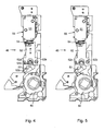
- the actuating unit 50 includes a conventional solenoid arrangement 51, including a coil and an armature which is able to move axially, up and down in Figs. 4 and 5 , in response to electrical power supply to the coil. This supply may be from an external source or from a battery (not shown) provided in the lock device.
- the solenoid arrangement 51 causes a fork-shaped extension part 52 to move reciprocatingly, as shown by the double-headed arrow in Fig. 4 .
- the fork-shaped part has two legs 52a, 52b, which embrace a point 53a of rotation of a rocker 53, which includes a magnet 53b on its outer end.
- the fork-shaped extension is also spring-biased in a downward direction in the figure, by means of a pressure spring 54.
- the function of the actuating unit will be described below with reference to Figs. 9-11 .
- the actuating unit is a separate component part. This enables a module construction to be obtained in which the actuating unit and the hub can be designed in accordance with specific requirements. It also enables the actual hub to be given a compact construction.
- the hub 60 will now be described in detail with reference to Figs. 6 and 7 .
- the hub includes an intermediate hub part 61, which lies between an upper, outer hub part 62 and a lower, outer hub part 63.
- the outer hub parts are identical mirror images of each other and are spring-biased by a respective handle follower spring 64a, 64b. These springs ensure that the handles coupled to the outer hub parts will be returned resiliently to their original positions.
- the upper outer hub part 62 has a centrally placed square opening 62a for receiving a handle pin (not shown), a coupling shoulder 62b and end-position shoulders 62c, 62d for rotational limitation.
- the lower outer hub part has corresponding features.
- the intermediate hub part 61 includes a bolt actuating projection 61a, which is coupled mechanically to the latch bolt 13 via the pressure rod 15, for movement of the latch bolt between its outer and inner end positions.
- the intermediate hub part also includes a driving shoulder 61b, which is coupled mechanically to the cylinder follower unit 30, see Fig. 1 , so as to enable the intermediate hub part 61 to be caused to rotate for activation of the latch bolt 13 by cylinder actuation.
- An upper wing 65 and a lower wing 66 are mounted about a pin secured in the intermediate hub part 61. This enables the wings to move between a retracted coupling position, such as the upper wing 65 in Fig. 6 , and an outwardly extended release position, such as for the lower wing 66 in Fig. 6 .
- a retracted coupling position such as the upper wing 65 in Fig. 6
- an outwardly extended release position such as for the lower wing 66 in Fig. 6 .
- the wings 65, 66 engage with the coupling shoulders 62b, 63b of the outer hub parts so that the wing, and therewith the entire intermediate hub parts 61, will rotate together with the outer hub part for which the wing is in a coupling position.
- the outer hub part will rotate independently of the intermediate hub part and depression of a lever handle coupled to the outer hub part will have no influence on the intermediate hub part, which therefore fails to influence the position of the latch bolt 13.
- the handle function is thus deactivated when the wing is in a release position.
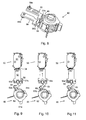
- the influence exerted by the wings 65, 66 in their respective positions will be described below with reference to Figs. 8-11 .
- the Fig. 8 embodiment includes respectively an upper and a lower adjustment arm 57, 58. These arms are movable between a coupling position such as with regard to the arm 57 in Fig. 8 , and a release position in regard of the arm 58 in said figure.
- the arms can be locked in position by means of a respective locking screw 59a, 59b, said screws extending through the casing 41 of the handle follower unit 40 and thus accessible from the outside; see, for instance, Fig. 1 .
- the adjustment arms actuate their respective wings in the following manner.
- a delimiting surface 57a, 58a of the adjustment arm prevents the wing from moving to its outwardly projected release position; see the arm 57 and the wing 65 in Fig. 8 .
- This will always prevent free-coupling between the intermediate hub part and the outer hub part, and the handle function in respect of the side concerned will thus always be engaged, regardless of the effect of the actuating means.
- the adjustment arm allows the wing to move to its release position (see the arm 58 and the wing 66 in Fig. 8 ) and the position of the wing will, instead, be determined by the actuating unit 50, as described below with reference to Figs. 9 and 10 .
- Fig. 9 shows the actuating unit 50 and the solenoid arrangement in the absence of voltage application.
- the forked element is shown in its lower end position.
- the rocker 53 is therewith rotated clockwise to a maximum and has drawn therewith the wings 65, 66 to their release position through the agency of a magnetic force, provided that none of the adjustment arms 57, 58 prevents this from taking place with regard to a respective wing 65 or 66.
- the handle function is thus deactivated or disengaged in the Fig. 9 illustration.
- Fig. 10 voltage has been applied to the solenoid arrangement and the solenoid has drawn the forked element 52 to an upper end position.
- the right-hand leg 52b of the forked element is connected to the rocker 53 by means of a screw 56 and the rocker 53 has therewith been rotated anti-clockwise maximally to a position in which the wings 65, 66 are prevented from leaving their coupling position.
- the upper outer hub part 62 is rotated clockwise in this position, by means of a handle having a handle pin inserted into the upper outer hub part, for instance, the outer hub part will cause co-rotation of the wing 65 and therewith also of the intermediate hub part, which, in turn, actuates the latch bolt 13.
- the wings 65 and 66 include an inclined abutment surface against the coupling shoulder 62b, 63b, which has a co-acting abutment surface, the wing will be locked in an inwardly retracted coupling position upon initial rotation of the outer hub part. It is therefore sufficient for the rocker 53 to hold in the wing for a limited length of time, for instance three seconds, provided that rotation of the outer hub part is initiated during this time period by pressing down the lever handle.
- Figs. 9 and 10 show an example where the handle function is disengaged in the absence of voltage application to the solenoid arrangement, so-called fail locked function.
- the rocker 53 is, instead, coupled to the left-hand leg of the forked element 52.
- the rocker 53 will, instead, rotate anti-clockwise.
- the lever handle function will be engaged when no voltage is applied to the solenoid arrangement 51, so-called fail unlocked function.
- the lock can be set to satisfy a user-desired function, by placing the screw 56 in an appropriate leg 52a, 52b. This can be readily achieved even when the lock device has been assembled, since the screw 56 can be accessed through openings provided in the cover plate of said device to this end; see Fig. 1 .
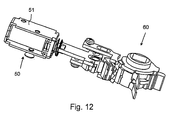
- Fig. 12 clearly shows the co-action between the actuating unit 50 and 60.
- the actuating unit 50 comprises a solenoid arrangement 51.
- This arrangement can be substituted by an electric motor used to move the rocker 53. The motor will draw current only when the link arm is moved and therewith enable the consumption of energy to be kept to a minimum, which is beneficial when the electrical energy source consists of a battery provided in the lock device.
- the hub 60 has been shown to include two wings 65, 66 for selective functioning of both sides of the lock, it will be understood that one wing may suffice when needing to actuate the function of only one side of the lock.
- This solution may be particularly relevant when the hub is mounted in a fitting on one side of a door. It will be understood that in this latter case, one of said outer hub parts may be omitted and the intermediate hub part coupled directly to a handle pin.
- the intermediate hub part is driven only in one direction. It will be understood, however, that the peripheral surfaces of the outer hub parts can be designed to drive the intermediate hub part in two directions.
- the wings 65, 66 have been described as being mounted on the intermediate hub part 61. It will be understood, however, that these wings or corresponding elements may, instead, be mounted on the outer hub parts and function to engage the intermediate hub part in said coupling position.
- outer hub parts 62, 63 have been described as including a respective wing-coupling shoulder 62b, 63b, such as to cause the intermediate hub part to rotate together with the outer hub parts in one direction of rotation. It will be understood, however, that a further coupling shoulder may be provided on each outer hub part, so that the intermediate hub part will rotate together with the outer hub parts in both rotational directions.
Landscapes
- Engineering & Computer Science (AREA)
- Structural Engineering (AREA)
- Lock And Its Accessories (AREA)
- Lasers (AREA)
- Laser Surgery Devices (AREA)
- Mechanical Operated Clutches (AREA)
Claims (13)
- Eine Zuhaltungseinheit zum Installieren in einer Schließvorrichtung, worin die Zuhaltungshaltungseinheit (30) umfasst:- ein elektrisch gesteuertes Bedienungsmittel (50);- eine Nabe (60), welche eine Nabenachse aufweist und angepasst ist, um zumindest einen Klinkenstift aufzunehmen, wobei die Nabe umfasst- einen ersten äußeren Nabenteil (62), welcher um die Nabenachse rotierbar ist und welcher angepasst ist, um einen ersten Klinkenstift aufzunehmen; ein Zwischennabenteil (61), welches um die Nabenachse rotierbar ist und an einen Bolzen in der Schließvorrichtung gekoppelt ist zur Bewegung des Bolzens zwischen einer äußeren und einer inneren Endposition; und- ein erstes Kopplungsmittel (65) welches unter der Steuerung des Betätigungsmittels zwischen einer Kopplungsposition, in welcher das Zwischennabenteil zusammen mit dem äußeren Nabenteil rotiert, und einer Löseposition, in welchem der erste äußere Nabenteil frei in Bezug auf den mittleren Nabenteil rotiert, bewegt, wobei das erste Kopplungsmittel um eine Achse rotierbar ist, welche sich im Allgemeinen im rechten Winkel zu der Nabenachse erstreckt,- wobei das Betätigungsmittel von der Nabe getrennt ist:
dadurch gekennzeichnet, dass- das Betätigungsmittel (50) eine Wippe (53) umfasst, welche zur Bewegung um einen Wippenbefestigungspunkt installiert ist, und welche, bei einer Drehung um diesen Punkt, eine Bewegung des Kupplungsmittels (65, 66) zwischen der Kupplungsposition und der Löseposition bewirkt; und- das Betätigungsmittel (50) ein reziprokbewegliches Gabel geformtes Teil (52) umfasst, welches an der Wippe (53) über zwei selektiv gewählte Krupplungspunkte verbunden ist, welche auf jeweiligen Seiten des Wippenbefestigungspunkts angeordnet sind. - Zuhaltungseinheit nach Anspruch 1, wobei die Einheit umfasst:- einen zweiten äußeren Wippeteil (63) welcher angepasst ist um einen zweiten Klinkenstift aufzunehmen, wobei das Zwischennabenteil (61) zwischen den ersten und zweiten äußeren Nabenteilen (62, 63) angeordnet ist;und
wobei die Zuhalteeinheit des Weiteren ein zweites Kupplungsmittel (66) umfasst, welches unter der Steuerung des Betätigungsmittels zwischen einer Kopplungsposition in welcher das Zwischennabenteil zusammen mit dem zweiten äußeren Nabenteil (63) rotiert, und einer Löseposition, in welcher das zweite äußere Nabenteil unabhängig von dem Zwischennabenteil rotiert, beweglich ist, wobei das zweite Kopplungsmittel um eine Achse, welche sich im Allgemeinen im rechten Winkel zu der Nabenachse erstreckt, rotierbar ist. - Zuhalteeinheit nach Anspruch 1 oder 2, in welcher das Kopplungsmittel (65, 66) an dem Zwischennabenteil (61) installiert ist.
- Zuhalteeinheit nach Anspruch 1 oder 2, in welcher das Kopplungsmittel (65, 66) an dem äußeren Nabenteil (62, 63) installiert ist.
- Zuhalteeinheit nach einem der Ansprüche 1 bis 4, in welchem der äußere Nabenteil (62, 63) eine Kuppelschulter (62b, 63b) umfasst, welche angepasst ist, um in den Kupplungsteil (65, 66) einzugreifen, wenn dieser Teil sich in seiner Kupplungsposition befindet.
- Zuhalteeinheit nach Anspruch 5, in welcher die Kupplungsschulter (62b, 63b) und der Kupplungsteil (65, 66) zusammenwirkende, geneigte Kupplungsoberflächen aufweisen, um den Kupplungsteil in seiner Kupplungsposition bei der Rotation des äußeren Nabenteils (62, 63) zu halten.
- Zuhalteeinheit nach einem der Ansprüche 1 bis 6, in welcher die Wippe einen Magneten (53b) umfasst, welcher vorgesehen ist, um das Kupplungsmittel (65, 66) zu bedienen.
- Zuhalteeinheit nach einem der Ansprüche 1 bis 7, wobei die Einheit eine Schraubenfeder (64a, 64b) umfasst, die zwischen dem äußeren Nabenteil (62, 63) und dem Zwischennabenteil (61) installiert ist und so wirkt, um den äußeren Nabenteil in eine Ausgangsposition zurückzubringen.
- Zuhalteeinheit nach einem der Ansprüche 1 bis 8, in welcher der äußere Nabenteil (62, 63) Endpositionsschultern (62c, 62d) zum Begrenzen einer Drehung des äußeren Nabenteils umfasst.
- Zuhalteeinheit nach einem der Ansprüche 1 bis 9, in welcher der Zwischennabenteil (61) eine Betätigungsschulter (61b) umfasst, welche zum mechanischen Koppeln an eine zweite Zuhalteeinheit angepasst ist, zum Drehen des Zwischennabenteils, unabhängig von dem äußeren Nabenteil (62, 63).
- Zuhalteeinheit nach einem der Ansprüche 1 bis 10, welche einen beweglichen Anpassungsarm (57, 58) umfasst, welcher eine Begrenzungsoberfläche 57a, 58a aufweist, welche es dem Kopplungsmittel (65, 66) ermöglicht, sich in seine Löseposition zu bewegen, in einer ersten Position des Anpassungsarms, und welches eine Bewegung des Kopplungsmittels zu seiner Löseposition in einer zweiten Position des Anpassungsarms verhindert.
- Zuhalteeinheit nach Anspruch 5, in welcher der äußere Nabenteil (62, 63) eine weitere Kopplungsschulter umfasst, welche zum Eingreifen mit dem Kupplungsteil (65, 66) angepasst ist, wenn das Kupplungsteil sich in seiner Kupplungsposition befindet, wobei die Kupplungsschulter und die weitere Kupplungsschulter in entgegen gesetzte Rotationsrichtung des äußeren Nabenteils ausgerichtet sind.
- Eine Schließvorrichtung umfassend eine Zuhalteeinheit nach einem der Ansprüche 1 bis 12.
Applications Claiming Priority (2)
| Application Number | Priority Date | Filing Date | Title |
|---|---|---|---|
| SE0300984A SE525521C2 (sv) | 2003-04-04 | 2003-04-04 | Elektrisk styrd roddarenhet samt låsanordning innefattande sådan enhet |
| PCT/SE2004/000518 WO2004088069A1 (en) | 2003-04-04 | 2004-04-02 | Electrically controlled follower unit and a lock device comprising such a unit |
Publications (2)
| Publication Number | Publication Date |
|---|---|
| EP1618271A1 EP1618271A1 (de) | 2006-01-25 |
| EP1618271B1 true EP1618271B1 (de) | 2009-12-23 |
Family
ID=20290923
Family Applications (1)
| Application Number | Title | Priority Date | Filing Date |
|---|---|---|---|
| EP04725575A Expired - Lifetime EP1618271B1 (de) | 2003-04-04 | 2004-04-02 | Elektrisch gesteuerte zuhaltereinheit und verriegelungsvorrichtung mit einer solchen einheit |
Country Status (6)
| Country | Link |
|---|---|
| EP (1) | EP1618271B1 (de) |
| AT (1) | ATE453032T1 (de) |
| DE (1) | DE602004024776D1 (de) |
| NO (1) | NO20055121L (de) |
| SE (1) | SE525521C2 (de) |
| WO (1) | WO2004088069A1 (de) |
Families Citing this family (7)
| Publication number | Priority date | Publication date | Assignee | Title |
|---|---|---|---|---|
| DE102010009557A1 (de) * | 2010-02-26 | 2011-09-01 | ASTRA Gesellschaft für Asset Management mbH & Co. KG | Elektronisches Einsteckschloss |
| DE102010017388A1 (de) * | 2010-06-16 | 2012-01-12 | Dom Sicherheitstechnik Gmbh & Co Kg | Vorrichtung zur Kupplung und Entkupplung eines Türaußendrückers |
| DE102014104139A1 (de) * | 2014-03-25 | 2015-10-01 | Assa Abloy Nederland B.V. | Schloss für Tür oder Fenster |
| US10657795B1 (en) | 2019-02-01 | 2020-05-19 | SimpliSafe, Inc. | Alarm system with first responder code for building access |
| EP3708745B1 (de) | 2019-03-13 | 2022-11-30 | Assa Abloy Opening Solutions Sweden AB | Elektromechanische schlossanordnung |
| ES2799578B2 (es) * | 2019-06-14 | 2022-03-24 | Salto Systems Sl | Cerradura de embutir de embrague simetrico y reversible |
| US11933092B2 (en) | 2019-08-13 | 2024-03-19 | SimpliSafe, Inc. | Mounting assembly for door lock |
Family Cites Families (7)
| Publication number | Priority date | Publication date | Assignee | Title |
|---|---|---|---|---|
| US4429556A (en) | 1981-08-13 | 1984-02-07 | Brink Locking Systems, Inc. | Lock mechanism |
| DE9114609U1 (de) | 1991-10-16 | 1992-02-06 | BKS GmbH, 5620 Velbert | Türschloß |
| DE29603652U1 (de) | 1996-02-28 | 1997-06-26 | Hewi Heinrich Wilke Gmbh, 34454 Arolsen | Beschlag für ein Schloß |
| FR2747149B1 (fr) | 1996-04-05 | 1998-06-12 | Fontaine Sa | Dispositif de commande electrique de verrouillage/deverrouillage d'une serrure presentant une fonction anti-panique et serrures anti-panique equipees d'un tel dispositif |
| FI110334B (fi) | 2001-01-24 | 2002-12-31 | Abloy Oy | Solenoidijärjestely painiketoiminnon ohjaamiseksi ovenlukossa |
| FI20010139L (fi) | 2001-01-24 | 2002-07-25 | Abloy Oy | Asennusjärjestely solenoidilla ohjattua painiketoimintoa varten ovenlukossa |
| FR2829518B1 (fr) * | 2001-09-11 | 2004-11-05 | Jpm Sa | Serrure a montage universel, dite"sans main" |
-
2003
- 2003-04-04 SE SE0300984A patent/SE525521C2/sv not_active IP Right Cessation
-
2004
- 2004-04-02 WO PCT/SE2004/000518 patent/WO2004088069A1/en not_active Ceased
- 2004-04-02 DE DE602004024776T patent/DE602004024776D1/de not_active Expired - Fee Related
- 2004-04-02 AT AT04725575T patent/ATE453032T1/de not_active IP Right Cessation
- 2004-04-02 EP EP04725575A patent/EP1618271B1/de not_active Expired - Lifetime
-
2005
- 2005-11-02 NO NO20055121A patent/NO20055121L/no not_active Application Discontinuation
Also Published As
| Publication number | Publication date |
|---|---|
| SE525521C2 (sv) | 2005-03-01 |
| ATE453032T1 (de) | 2010-01-15 |
| NO20055121L (no) | 2005-12-06 |
| NO20055121D0 (no) | 2005-11-02 |
| WO2004088069A1 (en) | 2004-10-14 |
| EP1618271A1 (de) | 2006-01-25 |
| SE0300984L (sv) | 2004-10-05 |
| SE0300984D0 (sv) | 2003-04-04 |
| DE602004024776D1 (de) | 2010-02-04 |
Similar Documents
| Publication | Publication Date | Title |
|---|---|---|
| EP1253266B1 (de) | Türschliessvorrichtung mit Schwenkhebelgriff | |
| EP1607558B1 (de) | Oberflächenmontiertes elektrisches Schliessblech | |
| EP2669454B1 (de) | Drehbare Sperrklinke | |
| US7766397B2 (en) | Electromechanical rotary pawl latch | |
| US6038896A (en) | Lockset with motorized system for locking and unlocking | |
| JP2511446B2 (ja) | カ−ド作動機構及びカ−ド作動式鎖錠装置 | |
| US8770633B2 (en) | Latch actuator and latch using same | |
| US20040177663A1 (en) | Override assembly for door lock systems having a clutch mechanism | |
| US4125008A (en) | Electrically operated lock | |
| AU2018308949B2 (en) | A mortice lock assembly with a powered lock actuator | |
| US7501930B2 (en) | Lock control system with lock-down feature | |
| KR20180114154A (ko) | 전기기계식 잠금 래치 | |
| US20090058596A1 (en) | Access control means with biometric sensor | |
| US20120025984A1 (en) | Lock With Electric Locking Function | |
| US20240218701A1 (en) | Strike linkage and in-wall receiver | |
| EP1618271B1 (de) | Elektrisch gesteuerte zuhaltereinheit und verriegelungsvorrichtung mit einer solchen einheit | |
| WO1998015703A1 (en) | Electro-mechanical lock | |
| US20240191546A1 (en) | Door-strike | |
| US20060112746A1 (en) | Electric lock device with manual redundancy | |
| CA2770128A1 (en) | Lock assembly | |
| US6386600B1 (en) | Vehicle door latch | |
| CN114450460B (zh) | 闩锁组件 | |
| KR100367630B1 (ko) | 자동잠김 기능을 갖는 전기정 | |
| KR100763884B1 (ko) | 도어록 장치 | |
| US7234329B2 (en) | Lock system for movable closure element |
Legal Events
| Date | Code | Title | Description |
|---|---|---|---|
| PUAI | Public reference made under article 153(3) epc to a published international application that has entered the european phase |
Free format text: ORIGINAL CODE: 0009012 |
|
| 17P | Request for examination filed |
Effective date: 20051027 |
|
| AK | Designated contracting states |
Kind code of ref document: A1 Designated state(s): AT BE BG CH CY CZ DE DK EE ES FI FR GB GR HU IE IT LI LU MC NL PL PT RO SE SI SK TR |
|
| AX | Request for extension of the european patent |
Extension state: AL HR LT LV MK |
|
| RAX | Requested extension states of the european patent have changed |
Extension state: LV Payment date: 20051026 Extension state: LT Payment date: 20051026 |
|
| 17Q | First examination report despatched |
Effective date: 20081008 |
|
| GRAP | Despatch of communication of intention to grant a patent |
Free format text: ORIGINAL CODE: EPIDOSNIGR1 |
|
| GRAC | Information related to communication of intention to grant a patent modified |
Free format text: ORIGINAL CODE: EPIDOSCIGR1 |
|
| GRAS | Grant fee paid |
Free format text: ORIGINAL CODE: EPIDOSNIGR3 |
|
| GRAA | (expected) grant |
Free format text: ORIGINAL CODE: 0009210 |
|
| AK | Designated contracting states |
Kind code of ref document: B1 Designated state(s): AT BE BG CH CY CZ DE DK EE ES FI FR GB GR HU IE IT LI LU MC NL PL PT RO SE SI SK TR |
|
| AX | Request for extension of the european patent |
Extension state: LT LV |
|
| REG | Reference to a national code |
Ref country code: GB Ref legal event code: FG4D |
|
| REG | Reference to a national code |
Ref country code: CH Ref legal event code: EP |
|
| REG | Reference to a national code |
Ref country code: IE Ref legal event code: FG4D |
|
| REF | Corresponds to: |
Ref document number: 602004024776 Country of ref document: DE Date of ref document: 20100204 Kind code of ref document: P |
|
| REG | Reference to a national code |
Ref country code: NL Ref legal event code: VDEP Effective date: 20091223 |
|
| PG25 | Lapsed in a contracting state [announced via postgrant information from national office to epo] |
Ref country code: SE Free format text: LAPSE BECAUSE OF FAILURE TO SUBMIT A TRANSLATION OF THE DESCRIPTION OR TO PAY THE FEE WITHIN THE PRESCRIBED TIME-LIMIT Effective date: 20091223 Ref country code: FI Free format text: LAPSE BECAUSE OF FAILURE TO SUBMIT A TRANSLATION OF THE DESCRIPTION OR TO PAY THE FEE WITHIN THE PRESCRIBED TIME-LIMIT Effective date: 20091223 |
|
| LTIE | Lt: invalidation of european patent or patent extension |
Effective date: 20091223 |
|
| PG25 | Lapsed in a contracting state [announced via postgrant information from national office to epo] |
Ref country code: PL Free format text: LAPSE BECAUSE OF FAILURE TO SUBMIT A TRANSLATION OF THE DESCRIPTION OR TO PAY THE FEE WITHIN THE PRESCRIBED TIME-LIMIT Effective date: 20091223 Ref country code: SI Free format text: LAPSE BECAUSE OF FAILURE TO SUBMIT A TRANSLATION OF THE DESCRIPTION OR TO PAY THE FEE WITHIN THE PRESCRIBED TIME-LIMIT Effective date: 20091223 |
|
| PG25 | Lapsed in a contracting state [announced via postgrant information from national office to epo] |
Ref country code: AT Free format text: LAPSE BECAUSE OF FAILURE TO SUBMIT A TRANSLATION OF THE DESCRIPTION OR TO PAY THE FEE WITHIN THE PRESCRIBED TIME-LIMIT Effective date: 20091223 |
|
| PG25 | Lapsed in a contracting state [announced via postgrant information from national office to epo] |
Ref country code: EE Free format text: LAPSE BECAUSE OF FAILURE TO SUBMIT A TRANSLATION OF THE DESCRIPTION OR TO PAY THE FEE WITHIN THE PRESCRIBED TIME-LIMIT Effective date: 20091223 Ref country code: BG Free format text: LAPSE BECAUSE OF FAILURE TO SUBMIT A TRANSLATION OF THE DESCRIPTION OR TO PAY THE FEE WITHIN THE PRESCRIBED TIME-LIMIT Effective date: 20100323 Ref country code: ES Free format text: LAPSE BECAUSE OF FAILURE TO SUBMIT A TRANSLATION OF THE DESCRIPTION OR TO PAY THE FEE WITHIN THE PRESCRIBED TIME-LIMIT Effective date: 20100403 Ref country code: PT Free format text: LAPSE BECAUSE OF FAILURE TO SUBMIT A TRANSLATION OF THE DESCRIPTION OR TO PAY THE FEE WITHIN THE PRESCRIBED TIME-LIMIT Effective date: 20100423 Ref country code: RO Free format text: LAPSE BECAUSE OF FAILURE TO SUBMIT A TRANSLATION OF THE DESCRIPTION OR TO PAY THE FEE WITHIN THE PRESCRIBED TIME-LIMIT Effective date: 20091223 Ref country code: NL Free format text: LAPSE BECAUSE OF FAILURE TO SUBMIT A TRANSLATION OF THE DESCRIPTION OR TO PAY THE FEE WITHIN THE PRESCRIBED TIME-LIMIT Effective date: 20091223 |
|
| PG25 | Lapsed in a contracting state [announced via postgrant information from national office to epo] |
Ref country code: BE Free format text: LAPSE BECAUSE OF FAILURE TO SUBMIT A TRANSLATION OF THE DESCRIPTION OR TO PAY THE FEE WITHIN THE PRESCRIBED TIME-LIMIT Effective date: 20091223 Ref country code: SK Free format text: LAPSE BECAUSE OF FAILURE TO SUBMIT A TRANSLATION OF THE DESCRIPTION OR TO PAY THE FEE WITHIN THE PRESCRIBED TIME-LIMIT Effective date: 20091223 Ref country code: CZ Free format text: LAPSE BECAUSE OF FAILURE TO SUBMIT A TRANSLATION OF THE DESCRIPTION OR TO PAY THE FEE WITHIN THE PRESCRIBED TIME-LIMIT Effective date: 20091223 |
|
| PG25 | Lapsed in a contracting state [announced via postgrant information from national office to epo] |
Ref country code: CY Free format text: LAPSE BECAUSE OF FAILURE TO SUBMIT A TRANSLATION OF THE DESCRIPTION OR TO PAY THE FEE WITHIN THE PRESCRIBED TIME-LIMIT Effective date: 20091223 Ref country code: GR Free format text: LAPSE BECAUSE OF FAILURE TO SUBMIT A TRANSLATION OF THE DESCRIPTION OR TO PAY THE FEE WITHIN THE PRESCRIBED TIME-LIMIT Effective date: 20100324 |
|
| PLBE | No opposition filed within time limit |
Free format text: ORIGINAL CODE: 0009261 |
|
| STAA | Information on the status of an ep patent application or granted ep patent |
Free format text: STATUS: NO OPPOSITION FILED WITHIN TIME LIMIT |
|
| PG25 | Lapsed in a contracting state [announced via postgrant information from national office to epo] |
Ref country code: MC Free format text: LAPSE BECAUSE OF NON-PAYMENT OF DUE FEES Effective date: 20100430 |
|
| REG | Reference to a national code |
Ref country code: CH Ref legal event code: PL |
|
| 26N | No opposition filed |
Effective date: 20100924 |
|
| GBPC | Gb: european patent ceased through non-payment of renewal fee |
Effective date: 20100402 |
|
| REG | Reference to a national code |
Ref country code: FR Ref legal event code: ST Effective date: 20101230 |
|
| PG25 | Lapsed in a contracting state [announced via postgrant information from national office to epo] |
Ref country code: DK Free format text: LAPSE BECAUSE OF FAILURE TO SUBMIT A TRANSLATION OF THE DESCRIPTION OR TO PAY THE FEE WITHIN THE PRESCRIBED TIME-LIMIT Effective date: 20091223 Ref country code: IE Free format text: LAPSE BECAUSE OF NON-PAYMENT OF DUE FEES Effective date: 20100402 |
|
| PG25 | Lapsed in a contracting state [announced via postgrant information from national office to epo] |
Ref country code: CH Free format text: LAPSE BECAUSE OF NON-PAYMENT OF DUE FEES Effective date: 20100430 Ref country code: LI Free format text: LAPSE BECAUSE OF NON-PAYMENT OF DUE FEES Effective date: 20100430 Ref country code: DE Free format text: LAPSE BECAUSE OF NON-PAYMENT OF DUE FEES Effective date: 20101103 |
|
| PG25 | Lapsed in a contracting state [announced via postgrant information from national office to epo] |
Ref country code: GB Free format text: LAPSE BECAUSE OF NON-PAYMENT OF DUE FEES Effective date: 20100402 Ref country code: IT Free format text: LAPSE BECAUSE OF FAILURE TO SUBMIT A TRANSLATION OF THE DESCRIPTION OR TO PAY THE FEE WITHIN THE PRESCRIBED TIME-LIMIT Effective date: 20091223 |
|
| PG25 | Lapsed in a contracting state [announced via postgrant information from national office to epo] |
Ref country code: FR Free format text: LAPSE BECAUSE OF NON-PAYMENT OF DUE FEES Effective date: 20100430 |
|
| PG25 | Lapsed in a contracting state [announced via postgrant information from national office to epo] |
Ref country code: HU Free format text: LAPSE BECAUSE OF FAILURE TO SUBMIT A TRANSLATION OF THE DESCRIPTION OR TO PAY THE FEE WITHIN THE PRESCRIBED TIME-LIMIT Effective date: 20100624 Ref country code: LU Free format text: LAPSE BECAUSE OF NON-PAYMENT OF DUE FEES Effective date: 20100402 |
|
| PG25 | Lapsed in a contracting state [announced via postgrant information from national office to epo] |
Ref country code: TR Free format text: LAPSE BECAUSE OF FAILURE TO SUBMIT A TRANSLATION OF THE DESCRIPTION OR TO PAY THE FEE WITHIN THE PRESCRIBED TIME-LIMIT Effective date: 20091223 |