EP1618008B1 - Writing assembly in combination with an eraser assembly - Google Patents
Writing assembly in combination with an eraser assembly Download PDFInfo
- Publication number
- EP1618008B1 EP1618008B1 EP04760208A EP04760208A EP1618008B1 EP 1618008 B1 EP1618008 B1 EP 1618008B1 EP 04760208 A EP04760208 A EP 04760208A EP 04760208 A EP04760208 A EP 04760208A EP 1618008 B1 EP1618008 B1 EP 1618008B1
- Authority
- EP
- European Patent Office
- Prior art keywords
- cap
- carrier
- eraser
- rib
- writing
- Prior art date
- Legal status (The legal status is an assumption and is not a legal conclusion. Google has not performed a legal analysis and makes no representation as to the accuracy of the status listed.)
- Expired - Lifetime
Links
- 239000000463 material Substances 0.000 claims abstract description 18
- 239000003550 marker Substances 0.000 claims description 7
- 239000004744 fabric Substances 0.000 claims description 2
- -1 felt Substances 0.000 claims description 2
- 239000006260 foam Substances 0.000 claims description 2
- 230000000295 complement effect Effects 0.000 description 4
- 239000000853 adhesive Substances 0.000 description 2
- 230000001070 adhesive effect Effects 0.000 description 2
- 239000000428 dust Substances 0.000 description 2
- 230000007246 mechanism Effects 0.000 description 2
- 229920006395 saturated elastomer Polymers 0.000 description 2
- 239000011449 brick Substances 0.000 description 1
- 230000001680 brushing effect Effects 0.000 description 1
- 238000001035 drying Methods 0.000 description 1
- 239000002657 fibrous material Substances 0.000 description 1
- 238000012986 modification Methods 0.000 description 1
- 230000004048 modification Effects 0.000 description 1
- 230000003014 reinforcing effect Effects 0.000 description 1
Images


Classifications
-
- B—PERFORMING OPERATIONS; TRANSPORTING
- B43—WRITING OR DRAWING IMPLEMENTS; BUREAU ACCESSORIES
- B43K—IMPLEMENTS FOR WRITING OR DRAWING
- B43K23/00—Holders or connectors for writing implements; Means for protecting the writing-points
- B43K23/08—Protecting means, e.g. caps
- B43K23/12—Protecting means, e.g. caps for pens
-
- B—PERFORMING OPERATIONS; TRANSPORTING
- B43—WRITING OR DRAWING IMPLEMENTS; BUREAU ACCESSORIES
- B43K—IMPLEMENTS FOR WRITING OR DRAWING
- B43K29/00—Combinations of writing implements with other articles
- B43K29/02—Combinations of writing implements with other articles with rubbers
-
- B—PERFORMING OPERATIONS; TRANSPORTING
- B43—WRITING OR DRAWING IMPLEMENTS; BUREAU ACCESSORIES
- B43K—IMPLEMENTS FOR WRITING OR DRAWING
- B43K8/00—Pens with writing-points other than nibs or balls
- B43K8/003—Pen barrels
-
- B—PERFORMING OPERATIONS; TRANSPORTING
- B43—WRITING OR DRAWING IMPLEMENTS; BUREAU ACCESSORIES
- B43K—IMPLEMENTS FOR WRITING OR DRAWING
- B43K8/00—Pens with writing-points other than nibs or balls
- B43K8/02—Pens with writing-points other than nibs or balls with writing-points comprising fibres, felt, or similar porous or capillary material
- B43K8/024—Pens with writing-points other than nibs or balls with writing-points comprising fibres, felt, or similar porous or capillary material with writing-points comprising felt
-
- B—PERFORMING OPERATIONS; TRANSPORTING
- B43—WRITING OR DRAWING IMPLEMENTS; BUREAU ACCESSORIES
- B43L—ARTICLES FOR WRITING OR DRAWING UPON; WRITING OR DRAWING AIDS; ACCESSORIES FOR WRITING OR DRAWING
- B43L19/00—Erasers, rubbers, or erasing devices; Holders therefor
- B43L19/0056—Holders for erasers
-
- B—PERFORMING OPERATIONS; TRANSPORTING
- B43—WRITING OR DRAWING IMPLEMENTS; BUREAU ACCESSORIES
- B43L—ARTICLES FOR WRITING OR DRAWING UPON; WRITING OR DRAWING AIDS; ACCESSORIES FOR WRITING OR DRAWING
- B43L19/00—Erasers, rubbers, or erasing devices; Holders therefor
- B43L19/0087—Assembling, repairing or finishing erasers
-
- B—PERFORMING OPERATIONS; TRANSPORTING
- B43—WRITING OR DRAWING IMPLEMENTS; BUREAU ACCESSORIES
- B43L—ARTICLES FOR WRITING OR DRAWING UPON; WRITING OR DRAWING AIDS; ACCESSORIES FOR WRITING OR DRAWING
- B43L21/00—Blackboard or slate cleaning devices
- B43L21/04—Wiper holders
Definitions
- the disclosure is directed to a writing assembly with an eraser assembly.
- Dry erase markers may be used to mark on a dry erase marking board, which may also be referred to as a whiteboard, in a temporary fashion. That is, the ink used in such dry erase markers may be formulated to dry quickly on the surface of the marking board, and to be removable from the surface of the marking board by brushing the dried ink off using an object made with a material such as felt.
- the object may be shaped in the form of a brick, and thus may be similar in appearance to a traditional chalk eraser.
- the material may be attached to a portion of the dry erase marker or to a holder for the dry erase marker.
- the ease of use such devices may present a problem, as the eraser material may be disposed for use with the marker only in one of a storage state and an operational state.
- the eraser material becomes saturated with dry erase ink, ink dust or other materials, continued use, disposal, and/or replacement of the eraser material may present problems.
- US 6,048,121 A illustrates a dry marker and eraser system. While US 6,048,121 A discusses a number of mechanisms for attaching an eraser to a cap, it does not suggest a mounting the eraser on a carrier that is then attached to the end of the cap with axially facing surfaces.
- US 5,947,624 A illustrates a capillary feed ink marker with a cap having a dry eraser attached thereto.
- the eraser is disposed in an axial bore of the cap.
- GB 595,461 A illustrates an eraser assembly for a mechanical pencil or pen/pencil.
- the eraser is disposed in an axial bore in a cap, and maintained through a spring-assisted friction fit.
- US 5,855,442 A illustrates a whiteboard marking pen with an eraser attached to various locations on the pen or the cap.
- the cap has a first end that covers the first end of the pen in a capped state, and a second end that fits into the second end of the pen in an uncapped state.
- the eraser is disposed in pockets formed on or in the first end of the cap. In other instances, the eraser is attached to the second end of the pen or the first end of the cap with adhesive.
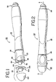
- Fig. 1 is a partially exploded view of a first example of a writing assembly
- Fig. 2 is a plan view of the writing assembly of Fig 1 , assembled
- Fig. 3 is a cross-sectional view of the pen of Fig. 2 taken about line 3-3 in Fig. 2 , with the cap in a first, storage state;
- Fig. 4 is a cross-sectional view of the pen of Fig. 2 taken about line 3-3 in Fig. 2 , with the cap in a second, operational state;
- Fig. 5 is a partial cross-sectional view of a second example of a writing assembly.
- Fig. 6 is a partial cross-sectional view of a third example of a writing assembly.
- Fig. 1 shows an example of a writing assembly 20 which includes a writing instrument 22; in the instant case, the writing instrument 22 may be a dry-erase marker.
- the writing assembly 20 also includes a cap 24, which may be disposed on a first end 26 of the writing instrument 22, as shown in Figs. 1, 2 and 3 , or on the second end 28 of the writing instrument 22, as shown in Fig. 4 .
- the writing assembly 20 further includes an eraser assembly 30, which is shown in exploded view in Fig. 1 and as assembled in Figs. 2-4 . While the eraser assembly 30 may be detachable or removable from the cap 24 as shown, the eraser assembly 30 may alternatively be fixedly attached or permanently attached to the cap 24.
- the writing instrument 22 may include a body 32 and a writing point 34.
- the body 32 may have a first, open end 36 and a second, closed end 38.
- the writing point 34 may depend from the first, open end 36 of the body 32, and may be made from a fibrous material, such as felt, so as to provide a mechanism for conveying an ink, such as a dry-erase ink, from a reservoir (not shown) disposed within the body 32.
- Both ends 36, 38 of the writing instrument 22 may be tapered and stepped.
- the first end 36 may have a first stepped region 40 defined by a shoulder 42 and a second stepped region 44 defined by a shoulder 46.
- the second end 38 may have a first stepped region 48 defined by a shoulder 50 and second stepped region 52 defined by a shoulder 54.
- the first stepped regions 40, 48 and second stepped regions 44, 52 may be similar in shape and curvature.
- the cap 24 has a first end 60 and a second end 62.
- a wall 64 may extend axially from the first end 60 to the second end 62.
- the wall 64 may have a rim 66 at the first end 60 that may define an opening 68.
- the wall 64, and in particular the inner surface 70 of the wall 64, may define a space or receptacle 72 therein that is in communication with the opening 68.
- the wall 64 may be closed at the second end 62 of the cap 24.
- the wall 64 and in particular the inner surface 70 of the wall 64, may be stepped.
- the inner surface 70 may have a first stepped region 74 defined by a shoulder 76 and a second stepped region 78 defined by a shoulder 80.
- the first stepped region 74 may be complementary to the first stepped regions 40, 48 of the first and second ends 36, 38 of the body 32
- the second stepped region 78 may be complementary to the second stepped regions 44, 52 of the first and second ends 36, 38 of the body 32.
- the wall 64 of the cap 24 may also define a post 82.
- the post 82 like the receptacle 72, may extend from the first end 60 to the second end 62 of the cap 24.
- the post 82 may have an annular rib 84 (as best seen in Fig. 1 ) formed on an external surface 86 thereof nearest the second end 62 of the cap 24.
- the rib 84 may define an axially facing surface 88.
- the cap 24 may also include a wall 90.
- the wall 90 may extend axially from the first end 60 toward the second end 62.
- the wall 90 may be disposed radially outward of the post 82.
- the wall 90 and the post 82 an in particular the outer surface 86 of the post 82, may define therebetween a space 92.
- the space 92 defined therebetween may be an annular space.
- one or more ribs 94 may be disposed in the space 92 for purposes of reinforcing the wall 90.
- the wall 90 may have an outer rim 96.
- the rim 96 may be a circular rim.
- the post 82 may extend axially beyond the rim 96 of the wall 90 in the direction of the second end 62 of the cap 24.
- the rib 84 disposed on the post 82 may be disposed on the portion of the post 82 that extends axially beyond the rim 96 of the wall 90 in the direction of the second end 62 of the cap 24.
- the eraser assembly 30 may include a hat-shaped carrier 100 and a hemispherical-shaped form of eraser material 102 attached thereto.
- the hat-shaped carrier 100 may include a wall 104 that may define a central boss 106 and a radially outwardly extending flange 108 that may terminate in a circular rim 110.
- the portion of the wall 104 that defines the central boss 106 may have a surface 112 that may define a receptacle 114.
- the eraser material 102 which may be foam, felt, cloth or sponge, for example, may be disposed on a surface 116 of the wall 104 opposite the surface 112, and may be fixed thereto through the use of an adhesive material, for example.
- the eraser assembly 30 may be selectively attached to the second end 62 of the cap 24 in the following manner.
- the post 82 may be disposed into the receptacle 114 of the carrier 100 of the assembly 30.
- the rib 84 disposed on the outer surface 86 of the post 82 may be advanced past an edge 118 defining an opening 120 in communication with the receptacle 114.
- the edge 118 may also define an axially facing surface 122.
- the opening 120 may be smaller in effective diameter that the radially outermost portion of the rib 84, but not so much so that the post 82 is prevented from moving axially relative to the eraser assembly 30 while the eraser assembly 30 is being attached to the cap 24.
- the rib 84 and the edge 118 may cooperate to limit the relative axial movement between the cap 24 and the eraser assembly 30.
- the axially facing surfaces 88, 122 abut to limit the movement between the cap 24 and the eraser assembly 30.
- the eraser assembly 30 may thus be attached to the cap 24, but may be detached if sufficient force is applied to the eraser assembly 30 to force the rib 84 past the edge 118. With the eraser assembly 30 and the cap 24 thus secured, the rim 96 of the wall 90 may abut the rim 110 of the flange 108 of the carrier 100.
- the post 82 may not include a rib 84.
- the external surface 86 of the post 82 may have a section of effective diameter that is larger that the effective diameter of the opening 120, but not so much so that the post 82 is prevented from moving axially relative to the eraser assembly 30 while the eraser assembly 30 is being attached to the cap 24. It will thus be recognized that the section of the outer surface 86 may define one of the axially facing surfaces of the cap 24 and the eraser assembly 30 that cooperate to limit the relative axial movement between the cap 24 and the eraser assembly 30.
- the cap 24 may be attached to the writing instrument 22 either at the first end 26 or the second end 28.
- the writing instrument 22 may be disposed axially into the receptacle 72 defined by the wall 64 of the cap 24, until the shoulders 42, 76 and 46, 80 abut.
- the stepped regions 40, 74 and 44, 78 may form an interference fit which limits the movement of the cap 24 relative to the first end 26 of the writing instrument 22.
- the stepped regions 40, 74 may be tapered in a complementary fashion to enhance the interference fit.
- the writing point 34 may be disposed into the receptacle 72 to prevent drying out of the writing point 34.
- the cap 24 may be attached to the second end 28 of the writing instrument 22 by disposing the second end 28 of the writing instrument 22 into the receptacle 72, until shoulders 50, 76 and 54, 80 abut.
- the stepped regions 48, 74 and 52, 78 may form an interference fit which limits the movement of the cap 24 relative to the second end 28 of the writing instrument 22.
- a rib 130 may be disposed on an outer surface 132 of the second end 28 of the writing instrument 22 to cooperate with the inner surface 70 of the cap 24 to enhance the interference fit. In this state, the writing point 34 may be exposed to permit use of the writing point 34.
- the eraser material 102 may be disposed in such a manner that it is fully exposed for use in removing ink that has been applied to a surface, such as the surface of a dry erase marking board (which may also be referred to as a whiteboard). Moreover, given the detachable nature of the eraser assembly 30 from the cap 24, when, for example, the eraser material 102 becomes saturated with ink or ink dust, the eraser assembly 30 may be removed from the cap 24, and may be replaced with a new eraser assembly 30.
- the writing assembly 20' includes a writing instrument 22' and a cap 24'.
- the cap 24' may be similar to the cap 24 in that the cap 24' may have a first wall 64' that may define a receptacle 72' and a post 82', and a second wall 90' that may be disposed radially outward from the post 82' so as to define a space 92' between the post 82' and the second wall 90'.
- the second wall 90' may have a rim 96', and the post 82' may extend beyond the rim 96' of the second wall 90' and may have an annular rib 84' formed thereon on the portion of the post 82' that may extend axially beyond the rim 96' of the second wall 90'. Moreover, the rib 84' may define an axially facing surface 88'.
- the eraser assembly 30' of the example of Fig. 5 includes a carrier 150 and eraser material 102' attached to the carrier 150.
- the carrier 150 may be in the form of a cylinder into which the post 82' of the cap 24' may be disposed when the eraser assembly 30' is attached to the cap 24'.
- the carrier 150 includes a groove 152, which is complementary to and in which the rib 84' of the post 82' is disposed to limit the movement of the eraser assembly 30' and the cap 24' relative to each other.
- the groove 152 may define an axially facing surface 154 that abuts the axially facing surface 88' to limit the movement of the eraser assembly 30' and the cap 24' relative to each other.
- the writing assembly 20" includes a writing instrument 22" and a cap 24".
- the cap 24" may be similar to the cap 24 in that the cap 24" has a first wall 64" that may define a receptacle 72" and a post 82", and a second wall 90" may be disposed radially outward from the post 82" so as to form a space 92" between the post 82" and second wall 90".
- the second wall 90" may have a rim 96".
- the post 82" may not extend beyond the rim 96" of the second wall 90".
- the post 82" may not have an annular rib formed thereon; instead, an annular grove 158 may be formed in an outer surface 160 of the second wall 90".
- the groove 158 may define an axially facing surface 162.
- the eraser assembly 30" of the example of Fig. 6 includes a carrier 164 and eraser material 102" attached to a first surface 166 of the carrier 164.
- First and second concentric annular walls 168, 170 may depend from a second surface 172 of the carrier 164 opposite the first surface 166 of the carrier 164.
- the effective diameter and central placement of the first annular wall 168 may be such that the end of the post 82" may be disposed within the first annular wall 168 with the eraser assembly 30" attached to the cap 24".
- the effective diameter and placement of the second annular wall 170 about a radial outermost edge of the carrier 164 may be such that the second wall 90" of the cap 24" may be disposed within the second annular wall 10 with the eraser assembly 30" attached to the cap 24".
- the second annular wall 170 may have an annular rib 174 formed on a radially inwardly facing surface 176 of the second annular wall 170, and the rib 174 may be received within and cooperate with the annular groove 160 in the second wall 90" of the cap 24" to limit the axial movement of the eraser assembly 30" relative to the cap 24".
- the rib 174 may define an axially facing surface 178 that abuts the axially facing surface 162 to limit the movement of the eraser assembly 30" and the cap 24" relative to each other.
Landscapes
- Mechanical Pencils And Projecting And Retracting Systems Therefor, And Multi-System Writing Instruments (AREA)
Abstract
Description
- The disclosure is directed to a writing assembly with an eraser assembly.
- Dry erase markers may be used to mark on a dry erase marking board, which may also be referred to as a whiteboard, in a temporary fashion. That is, the ink used in such dry erase markers may be formulated to dry quickly on the surface of the marking board, and to be removable from the surface of the marking board by brushing the dried ink off using an object made with a material such as felt. The object may be shaped in the form of a brick, and thus may be similar in appearance to a traditional chalk eraser.
- Alternatively, the material may be attached to a portion of the dry erase marker or to a holder for the dry erase marker. However, the ease of use such devices may present a problem, as the eraser material may be disposed for use with the marker only in one of a storage state and an operational state. Moreover, if the eraser material becomes saturated with dry erase ink, ink dust or other materials, continued use, disposal, and/or replacement of the eraser material may present problems.
-
US 6,048,121 A illustrates a dry marker and eraser system. WhileUS 6,048,121 A discusses a number of mechanisms for attaching an eraser to a cap, it does not suggest a mounting the eraser on a carrier that is then attached to the end of the cap with axially facing surfaces. -
US 5,947,624 A illustrates a capillary feed ink marker with a cap having a dry eraser attached thereto. The eraser is disposed in an axial bore of the cap. -
GB 595,461 A -
US 5,855,442 A illustrates a whiteboard marking pen with an eraser attached to various locations on the pen or the cap. The cap has a first end that covers the first end of the pen in a capped state, and a second end that fits into the second end of the pen in an uncapped state. In certain embodiments, the eraser is disposed in pockets formed on or in the first end of the cap. In other instances, the eraser is attached to the second end of the pen or the first end of the cap with adhesive. -
Fig. 1 is a partially exploded view of a first example of a writing assembly; -
Fig. 2 is a plan view of the writing assembly ofFig 1 , assembled; -
Fig. 3 is a cross-sectional view of the pen ofFig. 2 taken about line 3-3 inFig. 2 , with the cap in a first, storage state; -
Fig. 4 is a cross-sectional view of the pen ofFig. 2 taken about line 3-3 inFig. 2 , with the cap in a second, operational state; -
Fig. 5 is a partial cross-sectional view of a second example of a writing assembly; and -
Fig. 6 is a partial cross-sectional view of a third example of a writing assembly. - The present application provides a writing assembly according to claim 1. Preferred embodiments are disclosed in the sub-claims.
-
Fig. 1 shows an example of awriting assembly 20 which includes awriting instrument 22; in the instant case, thewriting instrument 22 may be a dry-erase marker. Thewriting assembly 20 also includes acap 24, which may be disposed on afirst end 26 of thewriting instrument 22, as shown inFigs. 1, 2 and3 , or on thesecond end 28 of thewriting instrument 22, as shown inFig. 4 . Thewriting assembly 20 further includes aneraser assembly 30, which is shown in exploded view inFig. 1 and as assembled inFigs. 2-4 . While theeraser assembly 30 may be detachable or removable from thecap 24 as shown, theeraser assembly 30 may alternatively be fixedly attached or permanently attached to thecap 24. - Turning first to the
writing instrument 22 and with reference toFigs. 3 and 4 , it will be recognized that thewriting instrument 22 may include abody 32 and awriting point 34. Thebody 32 may have a first,open end 36 and a second, closedend 38. Thewriting point 34 may depend from the first,open end 36 of thebody 32, and may be made from a fibrous material, such as felt, so as to provide a mechanism for conveying an ink, such as a dry-erase ink, from a reservoir (not shown) disposed within thebody 32. - Both ends 36, 38 of the
writing instrument 22 may be tapered and stepped. As seen best inFig. 4 , thefirst end 36 may have a firststepped region 40 defined by ashoulder 42 and a secondstepped region 44 defined by ashoulder 46. Likewise, as best seen inFig. 3 , thesecond end 38 may have a firststepped region 48 defined by ashoulder 50 and secondstepped region 52 defined by a shoulder 54. For reasons that will become apparent, the firststepped regions stepped regions - The
cap 24 has afirst end 60 and asecond end 62. Awall 64 may extend axially from thefirst end 60 to thesecond end 62. Thewall 64 may have arim 66 at thefirst end 60 that may define anopening 68. Thewall 64, and in particular theinner surface 70 of thewall 64, may define a space orreceptacle 72 therein that is in communication with theopening 68. Thewall 64 may be closed at thesecond end 62 of thecap 24. - The
wall 64, and in particular theinner surface 70 of thewall 64, may be stepped. As shown inFig. 4 , theinner surface 70 may have a firststepped region 74 defined by ashoulder 76 and a second stepped region 78 defined by ashoulder 80. The firststepped region 74 may be complementary to the firststepped regions second ends body 32, while the second stepped region 78 may be complementary to the secondstepped regions second ends body 32. - The
wall 64 of thecap 24 may also define apost 82. As shown, thepost 82, like thereceptacle 72, may extend from thefirst end 60 to thesecond end 62 of thecap 24. Thepost 82 may have an annular rib 84 (as best seen inFig. 1 ) formed on anexternal surface 86 thereof nearest thesecond end 62 of thecap 24. Therib 84 may define an axially facingsurface 88. - The
cap 24 may also include awall 90. Thewall 90 may extend axially from thefirst end 60 toward thesecond end 62. Thewall 90, however, may be disposed radially outward of thepost 82. Thewall 90 and thepost 82, an in particular theouter surface 86 of thepost 82, may define therebetween aspace 92. Given the concentric arrangement of thepost 82 and thewall 90, thespace 92 defined therebetween may be an annular space. As shown, one ormore ribs 94 may be disposed in thespace 92 for purposes of reinforcing thewall 90. - The
wall 90 may have anouter rim 96. Given the cylindrical geometries used in this example, therim 96 may be a circular rim. As shown inFigs 1 ,3 and 4 , thepost 82 may extend axially beyond therim 96 of thewall 90 in the direction of thesecond end 62 of thecap 24. In particular, therib 84 disposed on thepost 82 may be disposed on the portion of thepost 82 that extends axially beyond therim 96 of thewall 90 in the direction of thesecond end 62 of thecap 24. - Returning now to
Fig. 1 , theeraser assembly 30 may include a hat-shaped carrier 100 and a hemispherical-shaped form oferaser material 102 attached thereto. The hat-shaped carrier 100 may include awall 104 that may define acentral boss 106 and a radially outwardly extendingflange 108 that may terminate in acircular rim 110. As best seen inFigs. 3 and 4 , the portion of thewall 104 that defines thecentral boss 106 may have asurface 112 that may define areceptacle 114. Theeraser material 102, which may be foam, felt, cloth or sponge, for example, may be disposed on asurface 116 of thewall 104 opposite thesurface 112, and may be fixed thereto through the use of an adhesive material, for example. - The
eraser assembly 30 may be selectively attached to thesecond end 62 of thecap 24 in the following manner. Thepost 82 may be disposed into thereceptacle 114 of thecarrier 100 of theassembly 30. As thepost 82 is advanced into thereceptacle 114, therib 84 disposed on theouter surface 86 of thepost 82 may be advanced past anedge 118 defining anopening 120 in communication with thereceptacle 114. Theedge 118 may also define anaxially facing surface 122. Theopening 120 may be smaller in effective diameter that the radially outermost portion of therib 84, but not so much so that thepost 82 is prevented from moving axially relative to theeraser assembly 30 while theeraser assembly 30 is being attached to thecap 24. However, once therib 84 is advanced past theedge 118, therib 84 and theedge 118 may cooperate to limit the relative axial movement between thecap 24 and theeraser assembly 30. As best seen inFig. 3 , theaxially facing surfaces cap 24 and theeraser assembly 30. Theeraser assembly 30 may thus be attached to thecap 24, but may be detached if sufficient force is applied to theeraser assembly 30 to force therib 84 past theedge 118. With theeraser assembly 30 and thecap 24 thus secured, therim 96 of thewall 90 may abut therim 110 of theflange 108 of thecarrier 100. - As an alternative, the
post 82 may not include arib 84. Instead theexternal surface 86 of thepost 82 may have a section of effective diameter that is larger that the effective diameter of theopening 120, but not so much so that thepost 82 is prevented from moving axially relative to theeraser assembly 30 while theeraser assembly 30 is being attached to thecap 24. It will thus be recognized that the section of theouter surface 86 may define one of the axially facing surfaces of thecap 24 and theeraser assembly 30 that cooperate to limit the relative axial movement between thecap 24 and theeraser assembly 30. - In use, the
cap 24 may be attached to thewriting instrument 22 either at thefirst end 26 or thesecond end 28. - For example, to attach the
cap 24 to thefirst end 26 of the writinginstrument 22, the writinginstrument 22 may be disposed axially into thereceptacle 72 defined by thewall 64 of thecap 24, until theshoulders regions cap 24 relative to thefirst end 26 of the writinginstrument 22. The steppedregions writing point 34 may be disposed into thereceptacle 72 to prevent drying out of thewriting point 34. - Similarly, the
cap 24 may be attached to thesecond end 28 of the writinginstrument 22 by disposing thesecond end 28 of the writinginstrument 22 into thereceptacle 72, untilshoulders regions cap 24 relative to thesecond end 28 of the writinginstrument 22. Moreover, arib 130 may be disposed on anouter surface 132 of thesecond end 28 of the writinginstrument 22 to cooperate with theinner surface 70 of thecap 24 to enhance the interference fit. In this state, thewriting point 34 may be exposed to permit use of thewriting point 34. - In either the storage state or the operational state, the
eraser material 102 may be disposed in such a manner that it is fully exposed for use in removing ink that has been applied to a surface, such as the surface of a dry erase marking board (which may also be referred to as a whiteboard). Moreover, given the detachable nature of theeraser assembly 30 from thecap 24, when, for example, theeraser material 102 becomes saturated with ink or ink dust, theeraser assembly 30 may be removed from thecap 24, and may be replaced with anew eraser assembly 30. - It will be recognized that numerous modifications and alternatives may be purposed to the writing
assembly 20 described above. In addition to those already mentioned, two further examples are provided inFigs. 5 and 6 . In the examples ofFigs. 5 and 6 , elements in common with the example of the writingassembly 20 shown inFigs. 1-4 are numbered similarly, but with a prime or double-prime to differentiate between the elements of the various examples. - In the example of
Fig. 5 , the writing assembly 20' includes a writing instrument 22' and a cap 24'. The cap 24' may be similar to thecap 24 in that the cap 24' may have a first wall 64' that may define a receptacle 72' and a post 82', and a second wall 90' that may be disposed radially outward from the post 82' so as to define a space 92' between the post 82' and the second wall 90'. The second wall 90' may have a rim 96', and the post 82' may extend beyond the rim 96' of the second wall 90' and may have an annular rib 84' formed thereon on the portion of the post 82' that may extend axially beyond the rim 96' of the second wall 90'. Moreover, the rib 84' may define an axially facing surface 88'. - The eraser assembly 30' of the example of
Fig. 5 includes acarrier 150 and eraser material 102' attached to thecarrier 150. Thecarrier 150 may be in the form of a cylinder into which the post 82' of the cap 24' may be disposed when the eraser assembly 30' is attached to the cap 24'. It will be noticed that in this example, thecarrier 150 includes agroove 152, which is complementary to and in which the rib 84' of the post 82' is disposed to limit the movement of the eraser assembly 30' and the cap 24' relative to each other. In particular, thegroove 152 may define anaxially facing surface 154 that abuts the axially facing surface 88' to limit the movement of the eraser assembly 30' and the cap 24' relative to each other. - In the example of
Fig. 6 , like that ofFigs. 1-4 and5 , the writingassembly 20" includes awriting instrument 22" and acap 24". Thecap 24" may be similar to thecap 24 in that thecap 24" has afirst wall 64" that may define areceptacle 72" and apost 82", and asecond wall 90" may be disposed radially outward from thepost 82" so as to form aspace 92" between thepost 82" andsecond wall 90". Further, thesecond wall 90" may have arim 96". However, thepost 82" may not extend beyond therim 96" of thesecond wall 90". Moreover, thepost 82" may not have an annular rib formed thereon; instead, anannular grove 158 may be formed in anouter surface 160 of thesecond wall 90". Thegroove 158 may define anaxially facing surface 162. - The
eraser assembly 30" of the example ofFig. 6 includes acarrier 164 anderaser material 102" attached to afirst surface 166 of thecarrier 164. First and second concentricannular walls second surface 172 of thecarrier 164 opposite thefirst surface 166 of thecarrier 164. The effective diameter and central placement of the firstannular wall 168 may be such that the end of thepost 82" may be disposed within the firstannular wall 168 with theeraser assembly 30" attached to thecap 24". The effective diameter and placement of the secondannular wall 170 about a radial outermost edge of thecarrier 164 may be such that thesecond wall 90" of thecap 24" may be disposed within the second annular wall 10 with theeraser assembly 30" attached to thecap 24". Further, the secondannular wall 170 may have anannular rib 174 formed on a radially inwardly facingsurface 176 of the secondannular wall 170, and therib 174 may be received within and cooperate with theannular groove 160 in thesecond wall 90" of thecap 24" to limit the axial movement of theeraser assembly 30" relative to thecap 24". In particular, therib 174 may define anaxially facing surface 178 that abuts theaxially facing surface 162 to limit the movement of theeraser assembly 30" and thecap 24" relative to each other.
Claims (11)
- A writing assembly comprising:a writing instrument (22) having a first end (26) with a marking point (34) depending therefrom and a second, opposite end (28);a cap (24) having a first end (60) with a receptacle (72) defined therein and a second end (62), the first end (26) of the writing instrument (22) disposed into the receptacle (72) of the cap (24) in a first, storage state and the second end (28) of the writing instrument (22) disposed into the receptacle of the cap (24) in a second, operational state; andan eraser assembly (30) separate from the cap (24) and including a carrier (100) and an eraser material (102) attached to the carrier (100), the carrier (100) attached to the second end (62) of the cap (24), the cap (24) and the carrier (100) each having one of a pair of axially facing surfaces (88, 112) formed thereon, the axially facing surface (88) on the cap (24) abutting the axially facing surface (112) on the carrier (100) with the eraser assembly (30) attached to the cap (24) and the axially facing surface (88) of the cap (24) disposed further axially from the first end (60) of the cap (24) than the axially facing surface (112) of the carrier (100) to limit the movement of the eraser assembly (30) and the cap (24) relative to each other.
- The writing assembly according to claim 1, wherein:the cap (24) has a post (82) with a rib (84) formed thereon, the rib (84) defining the axially facing surface (88) formed on the cap (24); andthe carrier (100) has an edge (118) that defines an opening (120), the edge (118) defining the axially facing surface (112) formed on the carrier (100),at least the part of the post (82) with the rib (84) formed thereon disposed through the opening (120) in the carrier (100) with the eraser assembly (30) attached to cap (24), the axially facing surfaces (88, 112) defined by the rib (84) and the edge (118) abutting to limit the movement of the eraser assembly (30) and the cap (24) relative to each other.
- The writing assembly according to claim 1, wherein:one of the cap (24') and the carrier (150) has a groove (152) that defines one of the pair of axially facing surfaces (88', 154) and the other of the cap (24) and the carrier (150) has a rib (84') that defines the other of the pair of axially facing surfaces (88', 154);the rib (84') disposed within the groove (152) with the eraser assembly (30) attached to the cap (24), the axially facing surfaces (88', 154) defined by the rib (84') and the groove (152) abutting to limit the movement of the eraser assembly (30) and the cap (24) relative to each other.
- The writing assembly according to claim 3, wherein:the cap (24') has a post (82') depending from the second end of the cap (24"), the post having a surface on which the rib is formed; andthe carrier has wall with an inner surface that defines a receptacle and has a groove formed therein,the post disposed within the receptacle and the rib disposed within the groove with the carrier attached to the cap.
- The writing assembly according to claim 3, wherein:the cap has an annular wall depending from the first end of the cap toward the second end of the cap and having an effective diameter and a radially exterior surface in which the groove is formed; andthe carrier has an annular wall having an effective diameter greater than the effective diameter of the cap and a radially inwardly facing surface on which the rib is formed,the annular wall of the cap disposed within the annular wall of the carrier and the rib of the carrier disposed within the groove of the cap with the carrier attached to the cap.
- The writing assembly according to claim 1, wherein:the cap comprises a post depending from the second end of the cap; andthe carrier has an opening formed therein, the post being received through the opening with the carrier attached to the second end of the cap.
- The writing assembly according to claim 6, wherein:the post has a rib formed on an outer surface thereof; andthe carrier having an edge defining the opening,the rib and the edge abutting with the eraser assembly attached to the second end of the cap to limit the movement of the eraser assembly and the cap relative to each other.
- The writing assembly according to claim 7, wherein:the carrier has a wall with a central boss and a flange that depends radially outwardly from the central boss,the boss having an open end defined by the opening and a closed end opposite the open end,the carrier having an edge formed about the opening that defines the opening; andthe rib of the post and the edge of the carrier abutting to limit the movement of the eraser assembly and the cap relative to each other.
- The writing assembly according to claim 8, wherein:the carrier has first and second opposing sides, the opening defined in the first side of the carrier and the eraser material disposed on the second side of the carrier.
- The writing assembly according to claim 1, wherein the eraser material is selected from the group of eraser materials consisting of foam, felt, cloth, and sponge.
- The writing assembly according to claim 1, wherein the writing instrument is a dry erase marker.
Applications Claiming Priority (2)
| Application Number | Priority Date | Filing Date | Title |
|---|---|---|---|
| US10/424,411 US6932531B2 (en) | 2003-04-28 | 2003-04-28 | Writing assembly with eraser assembly |
| PCT/US2004/009132 WO2004096577A2 (en) | 2003-04-28 | 2004-03-25 | Writing assembly in combination with eraser assembly |
Publications (2)
| Publication Number | Publication Date |
|---|---|
| EP1618008A2 EP1618008A2 (en) | 2006-01-25 |
| EP1618008B1 true EP1618008B1 (en) | 2012-01-11 |
Family
ID=33299355
Family Applications (1)
| Application Number | Title | Priority Date | Filing Date |
|---|---|---|---|
| EP04760208A Expired - Lifetime EP1618008B1 (en) | 2003-04-28 | 2004-03-25 | Writing assembly in combination with an eraser assembly |
Country Status (10)
| Country | Link |
|---|---|
| US (1) | US6932531B2 (en) |
| EP (1) | EP1618008B1 (en) |
| JP (1) | JP4662928B2 (en) |
| KR (1) | KR20060027312A (en) |
| CN (1) | CN100436161C (en) |
| AU (1) | AU2004234334B2 (en) |
| CA (1) | CA2521755A1 (en) |
| MX (1) | MXPA05011520A (en) |
| TW (1) | TW200520984A (en) |
| WO (1) | WO2004096577A2 (en) |
Families Citing this family (42)
| Publication number | Priority date | Publication date | Assignee | Title |
|---|---|---|---|---|
| US20050175390A1 (en) * | 2004-01-20 | 2005-08-11 | Meadwestvaco Corporation | Erasable writing system |
| US20050158113A1 (en) * | 2004-01-20 | 2005-07-21 | Wehmeyer Stephen D. | Erasable writing system |
| US7815388B2 (en) * | 2004-01-20 | 2010-10-19 | Meadwestvaco Corporation | Retractable writing surface |
| US7905672B2 (en) * | 2004-01-20 | 2011-03-15 | Meadwestvaco Corporation | Insertable dividers for a bound component |
| US7131785B1 (en) * | 2004-07-26 | 2006-11-07 | Amir A Mansouri | Chewable top for a wiring instrument |
| USD534211S1 (en) * | 2004-12-28 | 2006-12-26 | Staples The Office Superstore Llc | Marker handle and cap |
| USD541339S1 (en) * | 2005-02-05 | 2007-04-24 | Beifa Group Co., Ltd. | Highlighter |
| USD530746S1 (en) * | 2005-03-01 | 2006-10-24 | Sanford, L.P. | Marker |
| US7350996B2 (en) * | 2005-03-28 | 2008-04-01 | Sanford, L.P. | Retractable writing utensil |
| USD540382S1 (en) * | 2005-05-03 | 2007-04-10 | Beifa Group Co., Ltd. | Highlighter |
| WO2007038516A2 (en) * | 2005-09-26 | 2007-04-05 | Julia Rhodes | Hand-held dry-erase board system |
| CN201189781Y (en) * | 2005-09-26 | 2009-02-04 | 朱利亚·罗兹 | Hand-held dry erase board apparatus |
| US8591131B2 (en) * | 2005-09-26 | 2013-11-26 | Julia M. Rhodes | Hand-held dry-erase board system |
| US9381768B2 (en) | 2005-09-26 | 2016-07-05 | The Julia Marie Rhodes 2010 Revocable Trust | Hand-held dry-erase board system |
| US20070126225A1 (en) * | 2005-12-05 | 2007-06-07 | Busam Edward P | Repositionable insert |
| US20070234485A1 (en) * | 2006-04-07 | 2007-10-11 | Fiskars Brands, Inc. | Scissors with sheath having eraser portion |
| USD569428S1 (en) * | 2006-07-27 | 2008-05-20 | Beifa Group Co., Ltd. | Highlighter |
| USD573183S1 (en) * | 2006-08-22 | 2008-07-15 | Beifa Group Co., Ltd. | Dual-tip highlighter |
| USD566331S1 (en) * | 2006-09-08 | 2008-04-08 | Geka Brush Gmbh | Applicator for lip cosmetics |
| US7350995B1 (en) * | 2006-12-19 | 2008-04-01 | Rhodes Julia M | Marker eraser system |
| US7850382B2 (en) | 2007-01-18 | 2010-12-14 | Sanford, L.P. | Valve made from two materials and writing utensil with retractable tip incorporating same |
| US7488130B2 (en) | 2007-02-01 | 2009-02-10 | Sanford, L.P. | Seal assembly for retractable instrument |
| JP2010527742A (en) * | 2007-05-31 | 2010-08-19 | レックス メディカル リミテッド パートナーシップ | Left atrial appendage closure device |
| USD584771S1 (en) * | 2007-08-31 | 2009-01-13 | Matthew Gerules | Marker |
| US8226312B2 (en) | 2008-03-28 | 2012-07-24 | Sanford, L.P. | Valve door having a force directing component and retractable instruments comprising same |
| US20100080645A1 (en) * | 2008-09-27 | 2010-04-01 | Jiayi Wu | Whiteboard marker |
| US8221012B2 (en) | 2008-11-07 | 2012-07-17 | Sanford, L.P. | Retractable instruments comprising a one-piece valve door actuating assembly |
| US8393814B2 (en) | 2009-01-30 | 2013-03-12 | Sanford, L.P. | Retractable instrument having a two stage protraction/retraction sequence |
| KR101051971B1 (en) * | 2009-03-24 | 2011-07-26 | 주식회사 모리스 | Writing instruments at both ends simultaneously |
| JP5608015B2 (en) * | 2009-09-01 | 2014-10-15 | 三菱鉛筆株式会社 | Applicator with valve |
| USD654217S1 (en) * | 2011-07-12 | 2012-02-14 | Brodish Joey L | Dual dispenser |
| US9004792B2 (en) * | 2011-12-29 | 2015-04-14 | Sanford, L.P. | Eraser cap assembly for writing instrument |
| JP6133121B2 (en) * | 2012-05-08 | 2017-05-24 | 株式会社壽 | Writing instrument |
| JP6132396B2 (en) * | 2013-05-14 | 2017-05-24 | アネスト岩田株式会社 | Air brush |
| USD711467S1 (en) * | 2013-07-01 | 2014-08-19 | Julia Marie Rhodes 2010 Revocable Trust | White board |
| USD757850S1 (en) * | 2015-03-19 | 2016-05-31 | Ningbo Syloon Imp And Exp Co., Ltd | Stylus and pen with screen cleaner |
| US9969206B2 (en) | 2015-09-28 | 2018-05-15 | Kablooe Design, Inc. | Marker storage accessory |
| USD837885S1 (en) * | 2016-04-01 | 2019-01-08 | Sanford, Lp | Cap for a writing instrument |
| USD853490S1 (en) * | 2017-09-19 | 2019-07-09 | Sanford, L.P. | Pen |
| USD941513S1 (en) * | 2019-05-31 | 2022-01-18 | Shenzhen Seaboom Co., Ltd | Light-emitting pen |
| US11919324B2 (en) * | 2019-12-28 | 2024-03-05 | Kabushiki Kaisha Pilot Corporation | Soft member attachment structure and thermochromic writing instrument |
| JP7372855B2 (en) * | 2020-02-28 | 2023-11-01 | 株式会社パイロットコーポレーション | Soft member mounting structure |
Family Cites Families (46)
| Publication number | Priority date | Publication date | Assignee | Title |
|---|---|---|---|---|
| GB595461A (en) | 1945-02-01 | 1947-12-05 | Serafin Garcia Lopez | Improvements in or relating to caps of mechanical pencils or pen and pencil combinations |
| US1822166A (en) | 1930-02-15 | 1931-09-08 | Mabie Todd & Co | Fountain pen cap |
| US1925388A (en) | 1930-09-24 | 1933-09-05 | Gertrude Reinke | Eraser |
| US1998684A (en) | 1934-04-30 | 1935-04-23 | Musgrave William Edgar | Eraser attachment for lead pencils |
| US2069462A (en) | 1936-04-06 | 1937-02-02 | John H Rouse | Projectable eraser |
| US2205929A (en) | 1938-05-02 | 1940-06-25 | Musgrave Pencil Company Inc | Pencil attachment |
| CH459839A (en) | 1967-07-19 | 1968-07-15 | Rieter Ag Maschf | Method for generating a thread reserve on a cylindrical bobbin holder and device for carrying out the method |
| GB1335170A (en) | 1972-06-12 | 1973-10-24 | Biing Yan Guu | Writing implement |
| US3941488A (en) * | 1974-07-10 | 1976-03-02 | David Maxwell | Marker/anti-marker system |
| US4557618A (en) | 1981-12-25 | 1985-12-10 | Pentel Kabushiki Kaisha | Ink and eraser of the ink |
| USD279992S (en) | 1983-04-06 | 1985-08-06 | Gribb Stephen R | Dual tip marking instrument |
| US4594362A (en) | 1983-07-06 | 1986-06-10 | Creative Products Resource Associates, Ltd. | Friable foam textile cleaning stick |
| USD295878S (en) | 1985-06-10 | 1988-05-24 | John Lovell | Dual applicator marking instrument |
| US4755074A (en) | 1986-09-17 | 1988-07-05 | Roberts Myrtle M | Pencil sharpener |
| US4815881A (en) * | 1987-11-25 | 1989-03-28 | Chern Biing Hwang | Multi-purpose combination writing instrument |
| US4904101A (en) | 1988-03-14 | 1990-02-27 | Pentel Of America, Ltd. | Eraser dispenser and writing instrument equipped with eraser dispenser |
| US5427278A (en) | 1988-09-09 | 1995-06-27 | Gardner, Iii; William G. | Highlighting-ink remover applicator |
| USD314843S (en) | 1989-01-25 | 1991-02-19 | Norma Kamali, Inc. | Perfume atomizer |
| CA1314842C (en) | 1989-02-27 | 1993-03-23 | Roger Durand | Cap for a writing instrument |
| USD330388S (en) | 1989-08-21 | 1992-10-20 | Choi Byung S | Combined felt-tipped pen and eraser |
| US4979254A (en) | 1990-03-12 | 1990-12-25 | Naujock Gordon L | Eraser feeder |
| JPH05305794A (en) | 1992-03-02 | 1993-11-19 | Sakura Color Prod Corp | Coating tool and its cap |
| DE4230432C1 (en) | 1992-09-11 | 1993-10-07 | Pelikan Ag | Hand-held writing instrument with two writing or order elements |
| USD355933S (en) | 1994-01-18 | 1995-02-28 | Collins Steven J | Combination writing instrument and bookmark |
| US5598604A (en) | 1995-05-08 | 1997-02-04 | Ho; Kun-Chuan | Pencil-shaped eraser |
| FR2736868B1 (en) | 1995-07-17 | 1997-10-10 | Conte | PENCIL WITH THE ERASER SUPPORT FERRULE IS FIXED BY ULTRA-SOUND WELDING AND SPECIALLY ADAPTED FERRULE |
| US5871294A (en) | 1996-01-16 | 1999-02-16 | Chelsea Group Ltd. | Felt tip pen cover with eraser |
| US6019535A (en) | 1996-01-16 | 2000-02-01 | Chelsea Group Ltd. | Felt-tip pen cover with eraser |
| US5855442A (en) * | 1996-11-15 | 1999-01-05 | Keller; Scott A. | Combined whiteboard marking pen and eraser |
| US5897266A (en) * | 1996-11-27 | 1999-04-27 | The Gillette Company | Vent system for writing instrument |
| US5947624A (en) * | 1997-04-07 | 1999-09-07 | Avery Dennison Corporation | Capillary feed ink marker assembly adapted for making erasable markings on the surface of a substantially non-porous marking substrate |
| GB2325649A (en) * | 1997-04-29 | 1998-12-02 | Pioneer Ind Corp | Cap with eraser for writing instrument |
| US5897265A (en) | 1997-05-06 | 1999-04-27 | Wilson; Caroline | Ink Eraser |
| US5890830A (en) | 1997-09-04 | 1999-04-06 | Pentech International Inc. | Universal marking instrument apparatus |
| JP3877844B2 (en) | 1997-09-12 | 2007-02-07 | 株式会社壽 | Writing instrument |
| US5957603A (en) | 1997-11-18 | 1999-09-28 | Bell; Charles E. | Combination support and eraser for a dry erase marker |
| US6048121A (en) | 1998-02-12 | 2000-04-11 | Cliperase, L.L.C. | Dry marker and eraser system |
| USD402691S (en) | 1998-02-26 | 1998-12-15 | Zbras Jr Richard T | Coloring implement guard |
| US6056468A (en) | 1998-10-02 | 2000-05-02 | Niewiadomski; Mitchell | Eraser for whiteboard marker |
| USD420048S (en) | 1999-03-04 | 2000-02-01 | Anson Sims | Motorized eraser |
| US6309129B1 (en) | 1999-07-06 | 2001-10-30 | Kotobuki & Co., Ltd. | Writing utensils |
| JP2001347792A (en) * | 2000-06-09 | 2001-12-18 | Taisei:Kk | Marker with eraser |
| USD452529S1 (en) | 2000-09-27 | 2001-12-25 | Kabushiki Kaisha Pilot | Container with extendable rod shaped solid |
| USD445130S1 (en) | 2001-01-08 | 2001-07-17 | Richard Ginelli | Trim double ended marker pen |
| USD456842S1 (en) | 2001-01-10 | 2002-05-07 | Pilot Precision Kabushiki Kaisha | Input pen with ball-point pen |
| US6347898B1 (en) | 2001-07-14 | 2002-02-19 | Julia Rhodes | Dry-ease marker eraser having a flexible tubular sleeve with internal ribs |
-
2003
- 2003-04-28 US US10/424,411 patent/US6932531B2/en not_active Expired - Lifetime
-
2004
- 2004-03-25 KR KR1020057020586A patent/KR20060027312A/en not_active Withdrawn
- 2004-03-25 WO PCT/US2004/009132 patent/WO2004096577A2/en not_active Ceased
- 2004-03-25 CA CA002521755A patent/CA2521755A1/en not_active Abandoned
- 2004-03-25 CN CNB2004800115870A patent/CN100436161C/en not_active Expired - Fee Related
- 2004-03-25 MX MXPA05011520A patent/MXPA05011520A/en active IP Right Grant
- 2004-03-25 EP EP04760208A patent/EP1618008B1/en not_active Expired - Lifetime
- 2004-03-25 JP JP2006509280A patent/JP4662928B2/en not_active Expired - Fee Related
- 2004-03-25 AU AU2004234334A patent/AU2004234334B2/en not_active Ceased
- 2004-04-26 TW TW093111635A patent/TW200520984A/en unknown
Also Published As
| Publication number | Publication date |
|---|---|
| EP1618008A2 (en) | 2006-01-25 |
| US20040213627A1 (en) | 2004-10-28 |
| JP2006524595A (en) | 2006-11-02 |
| HK1092430A1 (en) | 2007-02-09 |
| CN1780741A (en) | 2006-05-31 |
| WO2004096577A3 (en) | 2005-06-09 |
| CN100436161C (en) | 2008-11-26 |
| JP4662928B2 (en) | 2011-03-30 |
| AU2004234334B2 (en) | 2010-02-18 |
| MXPA05011520A (en) | 2006-01-23 |
| AU2004234334A1 (en) | 2004-11-11 |
| US6932531B2 (en) | 2005-08-23 |
| TW200520984A (en) | 2005-07-01 |
| KR20060027312A (en) | 2006-03-27 |
| CA2521755A1 (en) | 2004-11-11 |
| WO2004096577A2 (en) | 2004-11-11 |
Similar Documents
| Publication | Publication Date | Title |
|---|---|---|
| US6932531B2 (en) | Writing assembly with eraser assembly | |
| JP2006524595A5 (en) | ||
| US5895160A (en) | Universal marking instrument apparatus | |
| US5855442A (en) | Combined whiteboard marking pen and eraser | |
| US6347898B1 (en) | Dry-ease marker eraser having a flexible tubular sleeve with internal ribs | |
| US5871294A (en) | Felt tip pen cover with eraser | |
| WO2001025025A1 (en) | Writing instrument with integrated correction tape mechanism | |
| GB2325649A (en) | Cap with eraser for writing instrument | |
| CA1149779A (en) | Writing implement with improved cartridge holder | |
| MY117602A (en) | Writing tool | |
| JP2023011032A (en) | writing instrument | |
| HK1092430B (en) | Writing assembly in combination with eraser assembly | |
| KR200171233Y1 (en) | The ink eraser with rubber eraser | |
| CN221737480U (en) | A wide-head marking pen | |
| KR200266528Y1 (en) | Eraser of many functions | |
| CN212472895U (en) | Fluorescent marking pen | |
| JPH0120149Y2 (en) | ||
| KR200294779Y1 (en) | Writing tool having a cap | |
| KR200218165Y1 (en) | Two color double marker | |
| JPH0473589U (en) | ||
| JP2022189750A (en) | Mounting structure for soft member | |
| AU722292C (en) | Vent system for writing instrument | |
| JP3025656U (en) | Pen tip mechanism such as felt-tip pen | |
| JP2001334792A (en) | Caps for writing instruments | |
| JPS59148379U (en) | Structure of ink refill in ballpoint pen |
Legal Events
| Date | Code | Title | Description |
|---|---|---|---|
| PUAI | Public reference made under article 153(3) epc to a published international application that has entered the european phase |
Free format text: ORIGINAL CODE: 0009012 |
|
| 17P | Request for examination filed |
Effective date: 20051011 |
|
| AK | Designated contracting states |
Kind code of ref document: A2 Designated state(s): AT BE BG CH CY CZ DE DK EE ES FI FR GB GR HU IE IT LI LU MC NL PL PT RO SE SI SK TR |
|
| AX | Request for extension of the european patent |
Extension state: AL LT LV MK |
|
| RIN1 | Information on inventor provided before grant (corrected) |
Inventor name: ANDREWS, NEVILLE, E. Inventor name: MARSCHAND, BRET, R. |
|
| DAX | Request for extension of the european patent (deleted) | ||
| RBV | Designated contracting states (corrected) |
Designated state(s): DE FR GB IT |
|
| 17Q | First examination report despatched |
Effective date: 20091218 |
|
| RIC1 | Information provided on ipc code assigned before grant |
Ipc: B43K 29/02 20060101ALI20110805BHEP Ipc: B43L 21/04 20060101ALI20110805BHEP Ipc: B43L 19/00 20060101ALI20110805BHEP Ipc: B43K 23/12 20060101AFI20110805BHEP Ipc: B43K 8/02 20060101ALI20110805BHEP |
|
| GRAP | Despatch of communication of intention to grant a patent |
Free format text: ORIGINAL CODE: EPIDOSNIGR1 |
|
| GRAS | Grant fee paid |
Free format text: ORIGINAL CODE: EPIDOSNIGR3 |
|
| GRAA | (expected) grant |
Free format text: ORIGINAL CODE: 0009210 |
|
| AK | Designated contracting states |
Kind code of ref document: B1 Designated state(s): DE FR GB IT |
|
| REG | Reference to a national code |
Ref country code: GB Ref legal event code: FG4D |
|
| REG | Reference to a national code |
Ref country code: DE Ref legal event code: R096 Ref document number: 602004036105 Country of ref document: DE Effective date: 20120308 |
|
| PLBE | No opposition filed within time limit |
Free format text: ORIGINAL CODE: 0009261 |
|
| STAA | Information on the status of an ep patent application or granted ep patent |
Free format text: STATUS: NO OPPOSITION FILED WITHIN TIME LIMIT |
|
| PG25 | Lapsed in a contracting state [announced via postgrant information from national office to epo] |
Ref country code: IT Free format text: LAPSE BECAUSE OF FAILURE TO SUBMIT A TRANSLATION OF THE DESCRIPTION OR TO PAY THE FEE WITHIN THE PRESCRIBED TIME-LIMIT Effective date: 20120111 |
|
| 26N | No opposition filed |
Effective date: 20121012 |
|
| REG | Reference to a national code |
Ref country code: FR Ref legal event code: ST Effective date: 20121130 |
|
| GBPC | Gb: european patent ceased through non-payment of renewal fee |
Effective date: 20120411 |
|
| PG25 | Lapsed in a contracting state [announced via postgrant information from national office to epo] |
Ref country code: FR Free format text: LAPSE BECAUSE OF NON-PAYMENT OF DUE FEES Effective date: 20120402 Ref country code: GB Free format text: LAPSE BECAUSE OF NON-PAYMENT OF DUE FEES Effective date: 20120411 |
|
| REG | Reference to a national code |
Ref country code: DE Ref legal event code: R119 Ref document number: 602004036105 Country of ref document: DE Effective date: 20121002 |
|
| PG25 | Lapsed in a contracting state [announced via postgrant information from national office to epo] |
Ref country code: DE Free format text: LAPSE BECAUSE OF FAILURE TO SUBMIT A TRANSLATION OF THE DESCRIPTION OR TO PAY THE FEE WITHIN THE PRESCRIBED TIME-LIMIT Effective date: 20121002 |