EP1616829B1 - Yarn guide device of revolving type automatic winder - Google Patents
Yarn guide device of revolving type automatic winder Download PDFInfo
- Publication number
- EP1616829B1 EP1616829B1 EP04726013A EP04726013A EP1616829B1 EP 1616829 B1 EP1616829 B1 EP 1616829B1 EP 04726013 A EP04726013 A EP 04726013A EP 04726013 A EP04726013 A EP 04726013A EP 1616829 B1 EP1616829 B1 EP 1616829B1
- Authority
- EP
- European Patent Office
- Prior art keywords
- yarn
- bobbin
- guides
- turret
- guide
- Prior art date
- Legal status (The legal status is an assumption and is not a legal conclusion. Google has not performed a legal analysis and makes no representation as to the accuracy of the status listed.)
- Expired - Lifetime
Links
- 239000000463 material Substances 0.000 claims description 6
- 238000011144 upstream manufacturing Methods 0.000 claims description 5
- 238000009987 spinning Methods 0.000 abstract description 4
- 238000004804 winding Methods 0.000 description 23
- 230000001105 regulatory effect Effects 0.000 description 12
- 238000005304 joining Methods 0.000 description 8
- 230000003028 elevating effect Effects 0.000 description 6
- 238000004519 manufacturing process Methods 0.000 description 6
- 239000012530 fluid Substances 0.000 description 4
- 238000009434 installation Methods 0.000 description 3
- 238000000034 method Methods 0.000 description 3
- 239000012209 synthetic fiber Substances 0.000 description 2
- 229920002994 synthetic fiber Polymers 0.000 description 2
- 230000001133 acceleration Effects 0.000 description 1
- 238000007796 conventional method Methods 0.000 description 1
- 230000007423 decrease Effects 0.000 description 1
- 238000010586 diagram Methods 0.000 description 1
- 230000000694 effects Effects 0.000 description 1
- 230000002452 interceptive effect Effects 0.000 description 1
- 229920000728 polyester Polymers 0.000 description 1
Images



Classifications
-
- B—PERFORMING OPERATIONS; TRANSPORTING
- B65—CONVEYING; PACKING; STORING; HANDLING THIN OR FILAMENTARY MATERIAL
- B65H—HANDLING THIN OR FILAMENTARY MATERIAL, e.g. SHEETS, WEBS, CABLES
- B65H57/00—Guides for filamentary materials; Supports therefor
- B65H57/003—Arrangements for threading or unthreading the guide
-
- B—PERFORMING OPERATIONS; TRANSPORTING
- B65—CONVEYING; PACKING; STORING; HANDLING THIN OR FILAMENTARY MATERIAL
- B65H—HANDLING THIN OR FILAMENTARY MATERIAL, e.g. SHEETS, WEBS, CABLES
- B65H57/00—Guides for filamentary materials; Supports therefor
- B65H57/16—Guides for filamentary materials; Supports therefor formed to maintain a plurality of filaments in spaced relation
-
- B—PERFORMING OPERATIONS; TRANSPORTING
- B65—CONVEYING; PACKING; STORING; HANDLING THIN OR FILAMENTARY MATERIAL
- B65H—HANDLING THIN OR FILAMENTARY MATERIAL, e.g. SHEETS, WEBS, CABLES
- B65H65/00—Securing material to cores or formers
-
- B—PERFORMING OPERATIONS; TRANSPORTING
- B65—CONVEYING; PACKING; STORING; HANDLING THIN OR FILAMENTARY MATERIAL
- B65H—HANDLING THIN OR FILAMENTARY MATERIAL, e.g. SHEETS, WEBS, CABLES
- B65H67/00—Replacing or removing cores, receptacles, or completed packages at paying-out, winding, or depositing stations
- B65H67/04—Arrangements for removing completed take-up packages and or replacing by cores, formers, or empty receptacles at winding or depositing stations; Transferring material between adjacent full and empty take-up elements
- B65H67/044—Continuous winding apparatus for winding on two or more winding heads in succession
- B65H67/048—Continuous winding apparatus for winding on two or more winding heads in succession having winding heads arranged on rotary capstan head
-
- B—PERFORMING OPERATIONS; TRANSPORTING
- B65—CONVEYING; PACKING; STORING; HANDLING THIN OR FILAMENTARY MATERIAL
- B65H—HANDLING THIN OR FILAMENTARY MATERIAL, e.g. SHEETS, WEBS, CABLES
- B65H2701/00—Handled material; Storage means
- B65H2701/30—Handled filamentary material
- B65H2701/31—Textiles threads or artificial strands of filaments
Definitions
- the present invention relates to a yarn guiding device for a revolving type automaic winder according to the preamble of claim 1.
- a revolving type automatic winder as shown in Figure 11 is often used which is composed of one turret table 101 rotationally movably installed in a unit case 100, two bobbin holders 103a, 103b rotatably carried on the turret table 101 and on which bobbins 102a, 102b, respectively, are installed so that the yarns are wound around the bobbins 102a, 102b, a movable frame 104 that elevates and lowers in a vertical direction, a contact roller 105 rotatably attached to the movable frame 104, and a traverse device 106 located upstream side of the contact roller 105 as viewed in the direction of a yarn path.
- the Examined Japanese Patent Application Publication ( Tokkou-Hei) No. 5-17149 proposes a method for initial yarn catching in such a revolving type automatic winder.
- This method for initial yarn catching in a revolving type automatic winder is characterized by comprising separating the contact roller 105 from the bobbin holder 103a to set the contact roller 105 and the bobbin 102a in a non-contact state, moving a yarn catching guide 107 located at a standby position outside the turret table 101 so that the yarn catching guide 107 is located at a yarn catching position within a locus circle drawn by the bobbin holders 103a, 103b when the turret table 101 is rotationally moved, catching a yarn Y' on the yarn catching guide 107 while sucking the yarn Y' using a sucking device 108, increasing the speed of the yarn-catching side bobbin holder 103b to a value close to a steady-state winding speed, and rotationally
- the Japanese Patent Application No. 2002-239860 proposes a revolving type yarn winder comprising at least two bobbin holders rotatably installed on each of two turret tables, and a contact roller and a traverse device disposed upstream side of each of the turret tables in association with the bobbin holders so that when the amount of yarn wound around a bobbin installed on one of the bobbin holders reaches a predetermined amount, the bobbin is switched to one installed on the other bobbin holder to allow the yarn to be wound around this bobbin, the yarn winder being characterized in that the two turret tables are disposed across a yarn path, in that the contact roller installed for one of the turret tables rotates in a direction opposite to that in which the contact roller instal led for the other turret table rotates, and in that the center of each contact roller, which, during yarn winding, comes into contact with the bobbin
- the Examined Japanese Patent Application Publication ( Tokkou-Hei) No. 5-17149 requires that for initial yarn catching, the yarn catching guide move from the standby position outside the turret to the yarn catching position within the locus circle drawn by the bobbin holders when the turret is rotationally moved. Thus, the initial yarn catching is cumbersome. Further, the device according to the Japanese Patent Application No. 2002-239860 must have a complicated structure when the method according to the Examined Japanese Patent Application Publication ( Tokkou-Hei) No. 5-17149 is applied to this device. Consequently, the Examined Japanese Patent Application Publication ( Tokkou-Hei) No. 5-17149 cannot be put to practical.
- yarns Y are usually fed from an upstream side of the winder, and while being sucked by one suction gun SG, the yarns Y are conveyed to initial yarn catching guides 8, 8' via traversing fulcrum guides 10, 10', as shown in Figure 1 .
- the initial yarn catching guides 8, 8' are arranged laterally across a yarn path, it takes a long time to divert the yarns Y to the respective yarn catching guides 8, 8'.
- the one of the yarns Y is caught on one (for example, the left-hand initial yarn catching guide) 8' of the initial yarn catching guides 8, 8' before the other yarn Y is caught on the other (right-hand) initial yarn catching guide 8.
- This increases the time required for the operation because the yarns Y must be caught on the respective right and left initial yarn catching guides 8, 8'.
- This in turn increases the amount of yarn sucked by the suction gun SG during the catching operation, that is, the amount of yarn Y that must be disposed of. As a result, production efficiency decreases and production cost increases.
- a plurality of (in the present embodiment, eight) synthetic fiber yarns Y are wound around feeding rollers R1, R2; the yarns Y are continuously fed from a spinneret (not shown) of a spinning machine.
- a yarn guide G is disposed at an outlet of the feeding roller R2 to separate the plurality of yarns Y from one another at predetermined intervals.
- Traversing fulcrum guides 10, 10' are disposed downstream side of the feeding roller R2. As shown in Figure 6B , the traversing fulcrum guides 10, 10' regulate the plurality of yarns Y so that the yarns Y are arranged at intervals equal to those of a plurality of packages formed by a winder W.
- the plurality of traversing fulcrum guides 10, 10' can be moved closer to each other in an axial direction of bobbin holders 3, 4, 3', 4' and collectively toward an operation plane. This allows the yarns to be easily caught on the traversing fulcrum guides 10, 10'.
- a plurality of guide members 32 are arranged upstream side of a traverse device and in parallel in a direction orthogonal to the axial direction of the bobbin holders.
- Each of the guide members 32 is projected from a bracket 31 and provided with a pair of traversing fulcrum guides 10, 10'.
- the bracket 31 shown at the upper end of Figures 2A and 2B is fastened to a shaft 11, and the other brackets 31 can move on the shaft 11.
- the shaft 11 is pushed toward the interior of the machine body and the adjacent pairs of traversing fulcrum guides 10, 10' are separated from each other by a predetermined distance.
- the main body of a unit case 1 of the winder W is shaped like a rectangular parallelepiped.
- Bases 1' are provided at the bottom of the unit case 1 so as to extend to the vicinity of an operation space in front of the winder W (the left side of Figure 6 ).
- Disk-shaped turret tables 2, 2' are provided on a front surface of the unit case 1 so as to be rotationally movable around respective horizontally central axes.
- the turret tables 2, 2' are rotationally moved by driving means (not shown) such as a motor in opposite directions; the turret table 2 is rotationally moved clockwise, and the turret table 2' is rotationally moved counterclockwise.
- Two bobbin holders 3, 4, 3, 4' are rotatably projected from the turret tables 2, 2', in a direction perpendicular to the sheet of Figure 1 (in the direction of the sheet of Figure 6 ), and the bobbin holders 3, 4, 3', 4' are connected to a driving device (not shown). Accordingly, the two bobbin holders 3, 4 are rotated clockwise, while the other two bobbin holders 3', 4' are rotated counterclockwise. As shown in Figure 6 , eight bobbins B are installed on each of the bobbin holders 3, 4, 3', 4' according to the present embodiment.
- the elevating frame 5 carries contact rollers 6, 6' that contact bobbins B installed on the bobbin holders 3, 4, 3', 4' or yarn layers formed on the bobbins B, and also carries a traverse device (not shown) that traverses the yarns Y in the axial direction of the bobbins B. At least one of the contact rollers 6, 6' is borne by the elevating frame 5 so as to be pivotable independently of the elevating frame 5.
- the contract rollers 6, 6' feed the yarns Y to the bobbins B, while coming into pressure contact with the bobbins B or the yarn layers formed on the bobbins B.
- the contact rollers 6, 6' are contacted with the surfaces of packages in order to improve the shapes of the packages, while increasing the hardness of the packages.
- the centers of the contact rollers 6, 6' which contact the bobbin holders 3, 4, 3', 4' or the yarns Y being wound, are each located between an imaginary segment (c) joining the centers of the two bobbin holders 3, 4, projected from the one turret table 2 of the turret tables 2, 2', and an imaginary segment (c') joining the centers of the two bobbin holders 3', 4', projected from the other turret table 2'.
- the imaginary segments (c), (c') each joining the centers of the two bobbin holders 3, 4 or the two bobbin holders 3', 4' together form an inverted V shape at least at the position of winding start of the yarns Y.
- an angle ⁇ of at most 45 degrees to a vertical line (d) is formed by an imaginary segment joining the rotational center of each of the contact rollers 6, 6' that are in contact with each other and the rotational center of the bobbin holders 3, 3' , or 4, 4'.
- one traverse device is provided between the two contact rollers 6, 6'.
- the traverse device has a cylindrical cam (not shown) rotated by a driving device (not shown).
- a traverse guide engaged with a cam groove reciprocates in a lateral direction to traverse the yarn Y engaged with the traverse guide in the axial direction of the bobbin B within a traverse range.
- the two turret tables 2, 2' are disposed across a yarn path.
- the contact roller 6 provided for one turret table 2 of the turret tables 2, 2' rotates in the direction opposite to that in which the contact roller 6' provided for the other turret table 2' rotates.
- the one turret table 2 of the turret tables 2, 2' rotationally moves in the direction opposite to that in which the other turret table 2' rotationally moves. Accordingly, the width of the whole winder W can be reduced. This reduces the installation space for the winder W to improve the space efficiency.
- the traversing fulcrum guide moving shaft 11 is provided above the traverse device so as to extend parallel to the bobbin holders and in a substantially horizontal direction.
- the traversing fulcrum guide moving shaft 11 is provided with the plurality of traversing fulcrum guides 10, 10' in association with the bobbins B installed on the bobbin holders 3, 4, 3' , 4'.
- the traversing fulcrum guides 10, 10' are configured to be movable in the axial direction of the bobbin holders 3, 4, 3', 4'.
- the traversing fulcrum guides 10, 10' are fixed to positions corresponding to the center of each of the packages wound on the bobbins B installed on the bobbin holders 3, 4, 3', 4'.
- the traversing fulcrum guides 10, 10' move toward the leading end of each of the bobbin holders, that is, toward an operation side.
- Initial yarn catching guides 8, 8' are provided between and below the two turret tables 2, 2' to catch the yarns Y on the bobbins B installed on the bobbin holders 3, 4, 3', 4'.
- brackets 21 each comprising a cam groove 21a are provided in the lower part of a central portion of the unit case 1 so as to extend in a vertical direction.
- a lower end 14a of a yarn catching device 14 and a lower end 14a' of a yarn catching device 14' are pivotably instal led in the cam groove 21a in the bracket 21.
- the yarn catching devices 14, 14' can pivot around the lower ends 14a, 14'a and can also move along the cam groove 21a in the vertical direction.
- a link 22 connects the top of the yarn catching device 14 and the top of the bracket 21 together.
- the return position is located between loci (a), (a') drawn by the outer diameters of the bobbins when the turret tables 2, 2' are rotationally moved, the bobbins being installed on the bobbin holders, projected from the turret tables 2, 2'.
- the initial-catching operative portion is located beyond a tangent line (b), (b') between the contact rollers 6, 6' and the outer diameter of the bobbin B rotating in contact with the contact rollers 6, 6'.
- the plurality of initial yarn catching guides 8, 8' can be moved in a direction in which they are separated from one another.
- the yarn catching devices 14, 14' extend parallel to the bobbin holders 3, 4, 3', 4' and to the sheet of Figure 6 from the front surface of the unit case 1 to the vicinity of the operation space.
- Initial yarn catching guide moving shafts 9, 9' are provided at the upper ends of the yarn catching devices 14, 14', respectively, so as to be movable in the axial direction of the bobbin holders 3, 4, 3', 4' ; the initial yarn catching guide moving shafts 9, 9' each have a structure similar to that of the traversing fulcrum guide moving shaft 11.
- each of the initial yarn catching guides 8, 8' is composed of an L-shaped bar-like guide having a leading end facing toward the interior of the machine body.
- the bar-like guides engage with the yarns.
- the L-shaped leading ends guide the yarns while preventing them from falling.
- one yarn path fixing guide 7 is provided below the operation plane of the yarn catching devices 14, 14' for both turret tables 2, 2'.
- the yarn path fixing guide 7 is composed of a vertex 72 located on an extension of the yarn path midway between the two turret tables 2, 2' and positioning means 71, 71' being composed of concave portions formed on sides 70, 70', respectively, extended from the vertex 72 so as to form an isosceles triangle.
- the positioning means 71, 71' position the yarns fed from the traversing fulcrum guides to a suction gun SG so that the yarns are distributed in association with the turret tables 2, 2' and run along a yarn path corresponding to the plurality of yarn catching guides 8, 8'.
- the vertex 72 is located above the positioning means 71, 71'.
- the yarn path fixing guide 7 is formed of a bar material and has its root side connected to a plate material 73.
- the yarn path fixing guide 7 may be appropriately formed of a single plate member.
- the yarn path fixing guide 7 is preferably finely adjusted in a forward and backward directions as shown by an arrow in Figure 6A by, for example, forming slots 73a in the plate material 73 of the yarn path fixing guide 7 for mounting, as shown in Figure 5B .
- ends 18a, 18b of the plates 18, 18' are pivotably attached to the upper part of the central portion of the unit case 1.
- the plates 18, 18' can be pivoted around the respective ends 18a, 18a'.
- Yarn path regulating guides 17, 17' are attached to the plates 18, 18', respectively, to regulate the yarn path so as to prevent a yarn Y from falling from end surfaces of the package winding a predetermined amount of the yarn Y.
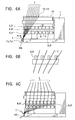
- a bundle of yarns Y is caught on the feeding rollers R1, R2 and yarn guide G below the spinneret of the spinning machine while being sucked by the suction gun SG. Then, the traversing fulcrum guide moving shaft 11 is pulled out toward the operation plane to move the traversing fulcrum guides 10, 10' (from positions corresponding to the centers of the bobbins) to the yarn catching operation side. The yarns Y are thus threaded through the traversing fulcrum guides 10, 10'. On this occasion, the initial yarn catching devices 14, 14' are located at their standby positions shown in Figure 3A .
- each of the yarns Y passes through a corresponding one of the eight initial yarn catching guides 8, 8' as shown in Figure 6B .
- the running position of each yarn Y is accurately set by the positioning means 71, 71' of the yarn path fixing guide 7.
- the spacing between the traveling fulcrum guides 10, 10' may be returned to the predetermined interval.
- the initial yarn catching devices 14, 14' are widely opened in the inverted V shape.
- each of the initial yarn catching devices 14, 14' is projected to a position where each of the initial yarn catching devices 14, 14' is located beyond an imaginary segment (b), (b'), joining the outer periphery of the contact rollers 6, 6' and the outer periphery of the bobbin B.
- Each of the yarns Y bent at each of the initial yarn catching guides 8, 8' is engaged with a yarn capturing groove S in each bobbin B. Then, winding of the yarn Y is started.
- the initial yarn catching devices 14, 14' are respectively returned to the area outside the loci (a), (a') drawn by the outer peripheries of the bobbins B installed on the bobbin holders 3 and 4, 3' and 4', and this prevents the outer peripheries of the bobbins installed on the bobbin holders from coming into contact with the yarn catching devices 14, 14'.
- the bobbin holder 3 rotates clockwise and the bobbin holder 3' rotates counterclockwise to wind the yarns Y around the bobbins B installed on the bobbin holders 3, 3'.
- the distance between the centers of the bobbin holders 3, 3' at a winding start position is shorter than the outer diameter of a full package. Accordingly, completely winding the yarn at the winding start position causes the full packages on the bobb i n holder 3 to collide with the full packages on the bobbin holder 3'.
- the winding packages are moved away from each other in a withdrawing direction while being thickened, so as to maintain a predetermined spacing between the winding packages. That is, at the beginning of winding of the yarn Y, the yarn Y is wound around the bobbin B installed on each of the bobbin holders 3, 3', with each of the turret tables 2, 2' fixed to a specified position. As the diameter of the package increases, each of the contact rollers 6, 6' moves upward together with the elevating frame 5.
- the turret tables 2, 2' are rotationally moved in a direction in which the spacing between the contact rollers 6, 6' and the bobbin holders 3, 3' is enlarged. That is, after the elevating frame 5 elevates to a predetermined position, the driving device (not shown) rotationally moves the turret table 2 clockwise and the turret table 2' counterclockwise at a very low speed. At the same time the yarns Y are respectively wound around the bobbins B installed on the bobbin holders 3, 3'.
- the turret table 2 is rotated clockwise and the turret table 2' is rotated counterclockwise, at a high speed.
- the yarn path regulating guides 17, 17' and the initial yarn catching guides 8, 8' advance between the bobbin holders 3, 4 and between the bobbin holders 3', 4' to engage the yarns with the yarn capturing grooves in the bobbins B installed on the bobbin holders.
- the yarns Y are then cut using the gripping force of the yarn capturing grooves, and now wound around the bobbins B installed on the bobbin holders 4, 4'.
- a fluid pressure cylinder (not shown) raises the leading end of the plates 18, 18' to place the yarn path regulating guides 17, 17' at the return position to prevent it from interfering with the yarn Y.
- the driving device rotationally moves the turret table 2 clockwise and the turret table 2' counterclockwise.
- the fluid pressure cylinder (not shown) lowers the leading ends of the plates 18, 18' to start moving the yarn path regulating guides 17, 17' from the return position to the operative position.
- the yarn path regulating guides 17, 17' regulate the yarn Y so as to prevent a yarn Y from falling from the end surface of the package winding a predetermined amount of the yarn Y.
- the yarn catching devices 14, 14' are widely opened in the inverted V shape as shown in Figure 4C .
- the yarn catching guides 8, 8' located at the leading end of the yarn catching devices 14, 14', are projected.
- the yarn path regulating guides 17, 17' and the yarn catching guides 8, 8' hold the yarn and engage the yarn Y with the yarn capturing groove in the empty bobbin B.
- a doffing device (not shown) discharges full packages formed around the bobbins B installed on the bobbin holders 3, 3' to the exterior of the winder.
- the plates 18, 18'and yarn path regulating guides 17, 17', and the yarn catching devices 14, 14' and yarn catching guides 8, 8' are returned from their operative positions to return positions once predetermined operations have been completed including catching of the yarns on the empty bobbins B installed on the bobbin holders 4, 4', discharge of full packages formed around the bobbins B installed on the bobbin holders 3, 3', and installation of empty bobbins on the bobbin holders 3, 3'.
- Figure 7 shows another embodiment of the traversing fulcrum guide.
- one guide member 32 is projected from each bracket 31, and the pair of traversing fulcrum guides 10, 10' is provided on each guide member 32.
- the two lateral guide members 32 and 32' are projected from the bracket 31.
- the guide members 32, 32' are provided with the respective traversing fulcrum guides 10, 10'.
- Figure 8 shows another embodiment of the traversing fulcrum guide.
- a traversing fulcrum guide aligning shaft 39 is provided parallel to the traversing fulcrum guide moving shaft 11 so as to be movable in the axial direction.
- the root of the guide member 32 is pivotably attached to the bracket 31.
- a lever 34 pivotably attached to the bracket 31 connects together the guide member 32 and a boss portion 36 to which the shaft 39 is attached. This structure allows the guide members 32 to be aligned together in a direction orthogonal to the axial direction of the bobbin holders as shown in Figure 8A and in the axial direction of the bobbin holders as shown in Figure 8C .
- Figure 9 shows another embodiment of the initial yarn catching guides 8, 8'.
- the lower ends of the L-shaped plates 14, 14' are pivotably borne on a bottom surface of a machine frame 1.
- the plates 14, 14' are moved by the fluid pressure cylinder (not shown) from its return position in the lower part of a central portion of the machine frame 1 (the position shown in Figure 9C ) to its initial-catching operative position (shown in Figure 9B ).
- the plates 14, 14' extend parallel to the axes of the bobbin holders 3, 4, 3', 4' (in the direction perpendicular to Figure 1 ) from the front surface of the machine frame 1 to the vicinity of the operation space.
- the initial yarn catching guides 8, 8' are respectively attached to the leading ends of the plates 14, 14' at a position corresponding to the yarn capturing grooves S, formed in the bobbins B installed on the bobbin holders 3, 4, 3', 4'.
- the initial yarn catching guides 8, 8' are movable between its return position and initial catching operative position together with the plates 14, 14'
- the plates 18, 18 and the yarn catching devices 14, 14' cooperate in switching full bobbins.
- desired operations can be performed using only the plates 18, 18' with the yarn catching devices 14, 14' remaining stopped.
- FIG 10 shows an embodiment of such plates.
- Yarn guides 16, 16' and the yarn path regulating guides 17, 17' are attached to the plates 18, 18, respectively, having an L-shaped cross section; each of the yarn guides 16, 16' guides the yarn Y to the yarn capturing groove S in the bobbin B and each of the yarn path regulating guides 17, 17' regulates the yarn path so that the yarn Y from falling from the end surface of the package winding a predetermined amount of the yarn Y.
- the leading ends of the plates 18, 18' are lowered and the yarn guides 16, 16' and yarn path regulating guides 17, 17' move from their return positions to operative positions.
- each of the yarn path regulating guides 17, 17' is regulating the yarn Y so as to prevent a yarn Y from falling from the end surface of the package winding a predetermined amount of the yarn Y
- the yarn guides 16, 16' are moved to engage the yarn Y with the yarn capturing groove in the empty bobbin B.
- the yarn path fixing guide is fixedly installed downstream of the turret table. After passing through the traversing fulcrum guide, the yarn is passed through the yarn path fixing guide while being sucked by the suction gun. Consequently, the yarn path is fixed to allow the yarn to be easily and reliably caught on the initial guide during initial yarn catching. Furthermore, since the yarn path guide is fixedly installed, the structure is simple, the facility cost is low, and the operations are easy.
- the yarns Y can be easily distributed to the turret tables during initial yarn catching. This reduces the operation time to improve the production efficiency.
- the winder comprises the positioning means for guiding the yarns Y to the initial yarn catching device. This enables the distributed yarns Y to be easily caught on the initial yarn catching device. Therefore, the operation time is further reduced to improve the production efficiency.
Landscapes
- Replacing, Conveying, And Pick-Finding For Filamentary Materials (AREA)
- Guides For Winding Or Rewinding, Or Guides For Filamentary Materials (AREA)
Abstract
Description
- The present invention relates to a yarn guiding device for a revolving type automaic winder according to the preamble of
claim 1. - In order to continuously wind synthetic fiber yarns such as polyester which are spun out from a spinneret of a spinning machine, a revolving type automatic winder as shown in
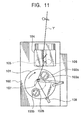
Figure 11 is often used which is composed of one turret table 101 rotationally movably installed in aunit case 100, twobobbin holders bobbins bobbins movable frame 104 that elevates and lowers in a vertical direction, acontact roller 105 rotatably attached to themovable frame 104, and atraverse device 106 located upstream side of thecontact roller 105 as viewed in the direction of a yarn path. - The Examined Japanese Patent Application Publication (
Tokkou-Hei) No. 5-17149 contact roller 105 from thebobbin holder 103a to set thecontact roller 105 and thebobbin 102a in a non-contact state, moving ayarn catching guide 107 located at a standby position outside the turret table 101 so that theyarn catching guide 107 is located at a yarn catching position within a locus circle drawn by thebobbin holders yarn catching guide 107 while sucking the yarn Y' using asucking device 108, increasing the speed of the yarn-catchingside bobbin holder 103b to a value close to a steady-state winding speed, and rotationally moving the turret table 101 to allow the yarn-catchingside bobbin holder 103b to grip the yarn Y', while bringing thecontact roller 105 into contact wi th thebobbin 102b installed on the yarn-catchingbobbin holder 103b, so that theyarn catching guide 107 is moved from the yarns catching position to the standby position, as shown inFigure 11 . - Further, the inventor has proposed a Japanese Patent Application No.
2002-239860 2002-239860 - The Examined Japanese Patent Application Publication (
Tokkou-Hei) No. 5-17149 2002-239860 Tokkou-Hei) No. 5-17149 Tokkou-Hei) No. 5-17149 - Further, in the revolving type yarn winder disclosed in the Japanese Patent Application No.
2002-239860 guides 8, 8' via traversingfulcrum guides Figure 1 . However, since the initial yarn catchingguides 8, 8' are arranged laterally across a yarn path, it takes a long time to divert the yarns Y to the respectiveyarn catching guides 8, 8'. Moreover, the one of the yarns Y is caught on one (for example, the left-hand initial yarn catching guide) 8' of the initial yarn catchingguides 8, 8' before the other yarn Y is caught on the other (right-hand) initialyarn catching guide 8. This increases the time required for the operation because the yarns Y must be caught on the respective right and left initial yarn catchingguides 8, 8'. This in turn increases the amount of yarn sucked by the suction gun SG during the catching operation, that is, the amount of yarn Y that must be disposed of. As a result, production efficiency decreases and production cost increases. - It is an object of the present invention to solve the above problems with the conventional techniques to provide a yarn guiding device that allows an easy and reliable initial yarn catching operation and to reduce the time required for the yarn catching operation, thus improving production efficiency.
- This object is accomplished by the features defined in the characterizing portion of
claim 1. -
-
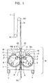
Figure 1 is a front view of an embodiment of a revolving type automatic winder according to the present invention. -
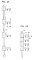
Figure 2 is a plan view of an embodiment of a traversing fulcrum guide;Figure 2A shows that a yarn Y is in a winding state andFigure 2B shows that the yarn Y is in a catching state. -
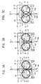
Figure 3 is a front view of an embodiment of an initial yarn catching guide;Figure 3A shows a steady-state winding state,Figure 3B shows how a yarn is caught on the initial yarn catching guide, andFigure 3C shows how the initial yarn catching guide catches the yarn on a bobbin on a bobbin holder. -
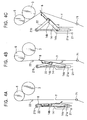
Figure 4 is a front view showing a mechanism that operates the initial yarn catching guide shown inFigure 3 (only one side of the initial yarn catching guide is shown);Figures 4A to 4C correspond to operations inFigures 3A to 3C . -
Figure 5 is a diagram showing an embodiment of a yarn path fixing device according to the present invention;Figure 5A is a side view andFigure 5B is a plan view. -
Figure 6 is a side view ofFigure 1 ;Figures 6A to 6C sequentially show an initial yarn catching operation. -
Figure 7 is a plan view of another embodiment of the traversing fulcrum guide;Figure 7A shows that the yarn Y is in the winding state andFigure 7B shows that the yarn Y is in the catching state. -
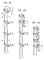
Figure 8 is a plan view of yet another embodiment of the traversing fulcrum guide;Figure 8A shows that the yarn Y is in the winding state andFigure 8C shows that the yarn Y changes to the catching state via a state shown inFigure 8B . -
Figure 9 is a front view of another embodiment of the initial yarn catching guide;Figure 9A shows the steady-state winding state,Figure 3B shows how a yarn is caught on the initial yarn catching guide, andFigure 9C shows how the initial yarn catching guide catches the yarn on the bobbin on the bobbin holder. -
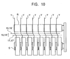
Figure 10 is a side view showing another embodiment of a plate. -
Figure 11 is a front view of an example of a conventional revolving type automatic winder. - In
Figure 1 , a plurality of (in the present embodiment, eight) synthetic fiber yarns Y are wound around feeding rollers R1, R2; the yarns Y are continuously fed from a spinneret (not shown) of a spinning machine. A yarn guide G is disposed at an outlet of the feeding roller R2 to separate the plurality of yarns Y from one another at predetermined intervals. -
Traversing fulcrum guides Figure 6B , thetraversing fulcrum guides - When the yarns Y are caught on the traversing
fulcrum guides fulcrum guides bobbin holders fulcrum guides - In the embodiment shown in
Figure 2 , a plurality ofguide members 32 are arranged upstream side of a traverse device and in parallel in a direction orthogonal to the axial direction of the bobbin holders. Each of theguide members 32 is projected from abracket 31 and provided with a pair of traversingfulcrum guides bracket 31 shown at the upper end ofFigures 2A and 2B is fastened to ashaft 11, and theother brackets 31 can move on theshaft 11. For steady-state winding, theshaft 11 is pushed toward the interior of the machine body and the adjacent pairs of traversingfulcrum guides shaft 11 is pulled out toward the operation plane (toward the bottom ofFigure 2 ). Thus, as shown inFigure 2B , the traversingfulcrum guides shaft 11 together with the upper-end bracket 31. The pairs of traversingfulcrum guides bobbin holders - In
Figure 1 , the main body of aunit case 1 of the winder W is shaped like a rectangular parallelepiped. Bases 1' are provided at the bottom of theunit case 1 so as to extend to the vicinity of an operation space in front of the winder W (the left side ofFigure 6 ). Disk-shaped turret tables 2, 2' are provided on a front surface of theunit case 1 so as to be rotationally movable around respective horizontally central axes. The turret tables 2, 2' are rotationally moved by driving means (not shown) such as a motor in opposite directions; the turret table 2 is rotationally moved clockwise, and the turret table 2' is rotationally moved counterclockwise. - Two
bobbin holders Figure 1 (in the direction of the sheet ofFigure 6 ), and thebobbin holders bobbin holders Figure 6 , eight bobbins B are installed on each of thebobbin holders - Two slide rails (not shown) are mounted inside the
unit case 1 so that anelevating frame 5 can be elevated and lowered along the slide rails using a fluid cylinder (not shown in the drawings). The elevatingframe 5 carriescontact rollers 6, 6' that contact bobbins B installed on thebobbin holders contact rollers 6, 6' is borne by the elevatingframe 5 so as to be pivotable independently of theelevating frame 5. - When the yarns Y are wound around the bobbins B installed on the
bobbin holders contract rollers 6, 6' feed the yarns Y to the bobbins B, while coming into pressure contact with the bobbins B or the yarn layers formed on the bobbins B. Thecontact rollers 6, 6' are contacted with the surfaces of packages in order to improve the shapes of the packages, while increasing the hardness of the packages. - In the present embodiment, the centers of the
contact rollers 6, 6', which contact thebobbin holders bobbin holders bobbin holders contact rollers 6, 6' that are in contact with each other and the rotational center of thebobbin holders - When switching of the yarns is started, that is, when rotational movement of the turret tables is started, acceleration of the turret tables enables the bobbin holders to push up the contact rollers. The bobbin holders can thus be rotated smoothly. Consequently, even at high turret speeds, it is possible to prevent damage caused by pressure contact or centering of the yarns in the front layers of the packages when the rotational movement of the turret tables is started. Therefore, the quality of wound yarns can be improved.
- Moreover, by providing the above geometric configuration and setting, at at most 45 degrees, the angle β between the vertical line (d) and the imaginary segment joining the rotational center of the
contact roller 6, 6' and the rotational center of thebobbin holders contact rollers 6, 6' in an almost vertical direction. This enables a reduction in the width L of the winder, thus improving the efficiency of an installation space. Therefore, space efficiency per production can be improved and facility cost can be reduced. - In the present embodiment, one traverse device is provided between the two
contact rollers 6, 6'. The traverse device has a cylindrical cam (not shown) rotated by a driving device (not shown). A traverse guide engaged with a cam groove reciprocates in a lateral direction to traverse the yarn Y engaged with the traverse guide in the axial direction of the bobbin B within a traverse range. - In the present embodiment, the two turret tables 2, 2' are disposed across a yarn path. The
contact roller 6 provided for one turret table 2 of the turret tables 2, 2' rotates in the direction opposite to that in which the contact roller 6' provided for the other turret table 2' rotates. Further, the one turret table 2 of the turret tables 2, 2' rotationally moves in the direction opposite to that in which the other turret table 2' rotationally moves. Accordingly, the width of the whole winder W can be reduced. This reduces the installation space for the winder W to improve the space efficiency. - Furthermore, as previously described, the traversing fulcrum
guide moving shaft 11 is provided above the traverse device so as to extend parallel to the bobbin holders and in a substantially horizontal direction. The traversing fulcrumguide moving shaft 11 is provided with the plurality of traversing fulcrum guides 10, 10' in association with the bobbins B installed on thebobbin holders - The traversing fulcrum guides 10, 10' are configured to be movable in the axial direction of the
bobbin holders bobbin holders - Initial yarn catching guides 8, 8' are provided between and below the two turret tables 2, 2' to catch the yarns Y on the bobbins B installed on the
bobbin holders - An embodiment of the initial yarn catching guides 8, 8' will be described with reference to
Figures 3 and4 . As shown inFigure 4 ,brackets 21 each comprising acam groove 21a are provided in the lower part of a central portion of theunit case 1 so as to extend in a vertical direction. Alower end 14a of ayarn catching device 14 and alower end 14a' of a yarn catching device 14' are pivotably instal led in thecam groove 21a in thebracket 21. Theyarn catching devices 14, 14' can pivot around the lower ends 14a, 14'a and can also move along thecam groove 21a in the vertical direction. Alink 22 connects the top of theyarn catching device 14 and the top of thebracket 21 together. With this link mechanism, thelower end yarn catching devices 14, 14' moves along thecam groove 21a from a return position where theyarn catching devices 14 , 14' are located parallel to each other in the lower part of a central portion of theunit case 1 as shown inFigures 3A and4A . Then, as shown inFigures 3B and4B , thelower end yarn catching devices 14, 14' moves through a yarn locking position where the top of eachyarn catching devices 14, 14' is slightly opened in an inverted V shape, then as shown inFigures 3C and4C , along thecam groove 21a to an initial-catching operative position where the top of each of theyarn catching devices 14, 14' is widely opened in the inverted V shape. - The return position is located between loci (a), (a') drawn by the outer diameters of the bobbins when the turret tables 2, 2' are rotationally moved, the bobbins being installed on the bobbin holders, projected from the turret tables 2, 2'. On the other hand, the initial-catching operative portion is located beyond a tangent line (b), (b') between the
contact rollers 6, 6' and the outer diameter of the bobbin B rotating in contact with thecontact rollers 6, 6'. At the yarn catching position, the plurality of initial yarn catching guides 8, 8' can be moved in a direction in which they are separated from one another. - The
yarn catching devices 14, 14' extend parallel to thebobbin holders Figure 6 from the front surface of theunit case 1 to the vicinity of the operation space. Initial yarn catchingguide moving shafts 9, 9' are provided at the upper ends of theyarn catching devices 14, 14', respectively, so as to be movable in the axial direction of thebobbin holders guide moving shafts 9, 9' each have a structure similar to that of the traversing fulcrumguide moving shaft 11. The initial yarn catchingguide moving shafts 9, 9', used to move the initialyarn catching guide 8, 8', engage with the initialyarn catching guide 8, 8' attached to theyarn catching devices 14, 14'. The initial yarn catchingguide moving shafts 9, 9' can thus move the initialyarn catching guide 8, 8' along theyarn catching device 14, 14' and parallel to thebobbin holders 3, 3'. As shown inFigure 6B , each of the initial yarn catching guides 8, 8' is composed of an L-shaped bar-like guide having a leading end facing toward the interior of the machine body. When the yarn catching guides 8, 8' are moved in the axial direction, the bar-like guides engage with the yarns. Then, the L-shaped leading ends guide the yarns while preventing them from falling. - In
Figures 1 and6 , one yarnpath fixing guide 7 is provided below the operation plane of theyarn catching devices 14, 14' for both turret tables 2, 2'. As shown inFigure 5 , the yarnpath fixing guide 7 is composed of avertex 72 located on an extension of the yarn path midway between the two turret tables 2, 2' and positioning means 71, 71' being composed of concave portions formed onsides 70, 70', respectively, extended from thevertex 72 so as to form an isosceles triangle. The positioning means 71, 71' position the yarns fed from the traversing fulcrum guides to a suction gun SG so that the yarns are distributed in association with the turret tables 2, 2' and run along a yarn path corresponding to the plurality of yarn catching guides 8, 8'. Thevertex 72 is located above the positioning means 71, 71'. - In the illustrated embodiment, the yarn
path fixing guide 7 is formed of a bar material and has its root side connected to aplate material 73. However, the yarnpath fixing guide 7 may be appropriately formed of a single plate member. The yarnpath fixing guide 7 is preferably finely adjusted in a forward and backward directions as shown by an arrow inFigure 6A by, for example, formingslots 73a in theplate material 73 of the yarnpath fixing guide 7 for mounting, as shown inFigure 5B . - Moreover, in
Figure 1 , ends 18a, 18b of theplates 18, 18' each having an L-shaped cross section are pivotably attached to the upper part of the central portion of theunit case 1. Theplates 18, 18' can be pivoted around the respective ends 18a, 18a'. Yarn path regulating guides 17, 17' are attached to theplates 18, 18', respectively, to regulate the yarn path so as to prevent a yarn Y from falling from end surfaces of the package winding a predetermined amount of the yarn Y. - A description will be given of operations performed by the device according to the present embodiment to carry out initial yarn catching and to switch full bobbins.
- A bundle of yarns Y is caught on the feeding rollers R1, R2 and yarn guide G below the spinneret of the spinning machine while being sucked by the suction gun SG. Then, the traversing fulcrum
guide moving shaft 11 is pulled out toward the operation plane to move the traversing fulcrum guides 10, 10' (from positions corresponding to the centers of the bobbins) to the yarn catching operation side. The yarns Y are thus threaded through the traversing fulcrum guides 10, 10'. On this occasion, the initialyarn catching devices 14, 14' are located at their standby positions shown inFigure 3A . - Subsequently, as shown in
Figure 6A , when the yarn Y is fed via the traversing fulcrum guides 10, 10', the operator operates the suction gun SG to thread the yarn Y, via a guide 23 (Figure 4 ) installed between thecontact rollers 6, 6' and the initialyarn catching devices 14, 14', through the positioning means 71, 71' of the yarnpath fixing guide 7. Thus, the yarn Y sucked from the traversing fulcrum guides 10, 10' into the sucking gun SG via the positioning means 71, 71' passes through the externally left or right side, inFigure 1 , of the initialyarn catching devices 14, 14' biased toward the front of the initialyarn catching devices 14, 14'. - As shown in
Figures 3B and4B , when the initial yarn catching guides 8, 8' are slightly opened in an inverted V shape, each of the yarns Y (in the present invention, eight yarns) passes through a corresponding one of the eight initial yarn catching guides 8, 8' as shown inFigure 6B . On this occasion, the running position of each yarn Y is accurately set by the positioning means 71, 71' of the yarnpath fixing guide 7. - Then, as shown in
Figure 6C , the traversing fulcrum guides 10, 10' and the initial yarn catching guides 8, 8' are moved to toward the interior of the machine to return the initial yarn catching guides 8, 8' to a predetermined position. In the meantime, the yarns Y are held on the yarn catching guides 8, 8'. - Before the yarns Y from the traveling fulcrum guides 10, 10' have been caught on the yarn
path fixing guide 7, the spacing between the traveling fulcrum guides 10, 10' may be returned to the predetermined interval. - As shown in
Figure 3C , the initialyarn catching devices 14, 14' are widely opened in the inverted V shape. In addition, each of the initialyarn catching devices 14, 14' is projected to a position where each of the initialyarn catching devices 14, 14' is located beyond an imaginary segment (b), (b'), joining the outer periphery of thecontact rollers 6, 6' and the outer periphery of the bobbin B. Each of the yarns Y bent at each of the initial yarn catching guides 8, 8' is engaged with a yarn capturing groove S in each bobbin B. Then, winding of the yarn Y is started. - Then, the initial
yarn catching devices 14, 14' are respectively returned to the area outside the loci (a), (a') drawn by the outer peripheries of the bobbins B installed on thebobbin holders yarn catching devices 14, 14'. - Then, a description will be given of operations performed by the device according to the embodiment from winding start to winding end.
- The
bobbin holder 3 rotates clockwise and the bobbin holder 3' rotates counterclockwise to wind the yarns Y around the bobbins B installed on thebobbin holders 3, 3'. - In the present invention, the distance between the centers of the
bobbin holders 3, 3' at a winding start position is shorter than the outer diameter of a full package. Accordingly, completely winding the yarn at the winding start position causes the full packages on the bobb i nholder 3 to collide with the full packages on the bobbin holder 3'. - The winding packages are moved away from each other in a withdrawing direction while being thickened, so as to maintain a predetermined spacing between the winding packages. That is, at the beginning of winding of the yarn Y, the yarn Y is wound around the bobbin B installed on each of the
bobbin holders 3, 3', with each of the turret tables 2, 2' fixed to a specified position. As the diameter of the package increases, each of thecontact rollers 6, 6' moves upward together with the elevatingframe 5. - Once the diameter of the package into which the yarn is wound reaches a predetermined dimension, the turret tables 2, 2' are rotationally moved in a direction in which the spacing between the
contact rollers 6, 6' and thebobbin holders 3, 3' is enlarged. That is, after the elevatingframe 5 elevates to a predetermined position, the driving device (not shown) rotationally moves the turret table 2 clockwise and the turret table 2' counterclockwise at a very low speed. At the same time the yarns Y are respectively wound around the bobbins B installed on thebobbin holders 3, 3'. - Now, a description will be given of operations performed by the device according to the embodiment to switch full bobbins.
- Once the amount of yarn Y wound on the bobbin B reaches a predetermined amount as previously described, the turret table 2 is rotated clockwise and the turret table 2' is rotated counterclockwise, at a high speed. The yarn path regulating guides 17, 17' and the initial yarn catching guides 8, 8' advance between the
bobbin holders bobbin holders 4, 4'. - When the amount of yarn Y wound around the bobbin B installed on the
bobbin holders 3, 3' reaches the predetermined amount, a fluid pressure cylinder (not shown) raises the leading end of theplates 18, 18' to place the yarn path regulating guides 17, 17' at the return position to prevent it from interfering with the yarn Y. - The driving device (not shown) rotationally moves the turret table 2 clockwise and the turret table 2' counterclockwise. The fluid pressure cylinder (not shown) lowers the leading ends of the
plates 18, 18' to start moving the yarn path regulating guides 17, 17' from the return position to the operative position. The yarn path regulating guides 17, 17' regulate the yarn Y so as to prevent a yarn Y from falling from the end surface of the package winding a predetermined amount of the yarn Y. At the same time, as in the case of the initial yarn catching, theyarn catching devices 14, 14' are widely opened in the inverted V shape as shown inFigure 4C . Further, the yarn catching guides 8, 8', located at the leading end of theyarn catching devices 14, 14', are projected. The yarn path regulating guides 17, 17' and the yarn catching guides 8, 8' hold the yarn and engage the yarn Y with the yarn capturing groove in the empty bobbin B. - After the rotation of the
bobbin holders 3, 3' are stopped, a doffing device (not shown) discharges full packages formed around the bobbins B installed on thebobbin holders 3, 3' to the exterior of the winder. - The
plates 18, 18'and yarn path regulating guides 17, 17', and theyarn catching devices 14, 14' and yarn catching guides 8, 8' are returned from their operative positions to return positions once predetermined operations have been completed including catching of the yarns on the empty bobbins B installed on thebobbin holders 4, 4', discharge of full packages formed around the bobbins B installed on thebobbin holders 3, 3', and installation of empty bobbins on thebobbin holders 3, 3'. -
Figure 7 shows another embodiment of the traversing fulcrum guide. In the embodiment shown inFigure 2 , oneguide member 32 is projected from eachbracket 31, and the pair of traversing fulcrum guides 10, 10' is provided on eachguide member 32. In the embodiment shown inFigure 7 , the twolateral guide members 32 and 32' are projected from thebracket 31. Theguide members 32, 32' are provided with the respective traversing fulcrum guides 10, 10'. -
Figure 8 shows another embodiment of the traversing fulcrum guide. In the embodiment shown inFigure 8 , a traversing fulcrumguide aligning shaft 39 is provided parallel to the traversing fulcrumguide moving shaft 11 so as to be movable in the axial direction. The root of theguide member 32, previously described, is pivotably attached to thebracket 31. Further, alever 34 pivotably attached to thebracket 31 connects together theguide member 32 and aboss portion 36 to which theshaft 39 is attached. This structure allows theguide members 32 to be aligned together in a direction orthogonal to the axial direction of the bobbin holders as shown inFigure 8A and in the axial direction of the bobbin holders as shown inFigure 8C . In order to catch the yarns on the traversing fulcrum guides 10, 10', all the traversing fulcrum guides 10, 10' are aligned together in the axial direction of the bobbin holders as shown inFigure 8C so as to facilitate yarn catching. After the yarn catching, as shown inFigure 8A , theguide member 32 is placed orthogonally to the axial direction of the bobbin holders so that traversing fulcrum guides 10, 10' are provided at a prescribed interval between one another in the same manner as the bobbin holders. -
Figure 9 shows another embodiment of the initial yarn catching guides 8, 8'. The lower ends of the L-shapedplates 14, 14' are pivotably borne on a bottom surface of amachine frame 1. Theplates 14, 14' are moved by the fluid pressure cylinder (not shown) from its return position in the lower part of a central portion of the machine frame 1 (the position shown inFigure 9C ) to its initial-catching operative position (shown inFigure 9B ). Theplates 14, 14' extend parallel to the axes of thebobbin holders Figure 1 ) from the front surface of themachine frame 1 to the vicinity of the operation space. The initial yarn catching guides 8, 8' are respectively attached to the leading ends of theplates 14, 14' at a position corresponding to the yarn capturing grooves S, formed in the bobbins B installed on thebobbin holders plates 14, 14' - In the above embodiments, the
plates yarn catching devices 14, 14' cooperate in switching full bobbins. However, desired operations can be performed using only theplates 18, 18' with theyarn catching devices 14, 14' remaining stopped. -
Figure 10 shows an embodiment of such plates. Yarn guides 16, 16' and the yarn path regulating guides 17, 17' are attached to theplates plates 18, 18' are lowered and the yarn guides 16, 16' and yarn path regulating guides 17, 17' move from their return positions to operative positions. While each of the yarn path regulating guides 17, 17' is regulating the yarn Y so as to prevent a yarn Y from falling from the end surface of the package winding a predetermined amount of the yarn Y, the yarn guides 16, 16' are moved to engage the yarn Y with the yarn capturing groove in the empty bobbin B. - According to the present invention, the yarn path fixing guide is fixedly installed downstream of the turret table. After passing through the traversing fulcrum guide, the yarn is passed through the yarn path fixing guide while being sucked by the suction gun. Consequently, the yarn path is fixed to allow the yarn to be easily and reliably caught on the initial guide during initial yarn catching. Furthermore, since the yarn path guide is fixedly installed, the structure is simple, the facility cost is low, and the operations are easy.
- According to the present invention, even in a winder with two turret tables arranged in parallel, the yarns Y can be easily distributed to the turret tables during initial yarn catching. This reduces the operation time to improve the production efficiency. Further, the winder comprises the positioning means for guiding the yarns Y to the initial yarn catching device. This enables the distributed yarns Y to be easily caught on the initial yarn catching device. Therefore, the operation time is further reduced to improve the production efficiency.
Claims (5)
- A yarn guiding device for a revolving type automatic winder comprising at least two bobbin holders (3, 3', 4, 4') rotatably installed on each of two turret tables (2, 2') disposed across a yarn path, a traversing fulcrum guide (10, 10'), a contact roller (6, 6'), a traverse device disposed upstream side of each of the turret tables in association with the bobbin holders so that when the amount of yarn wound around a bobbin installed on one of the bobbin holders reaches a predetermined amount, the bobbin is switched, on both turret tables, to the one installed on the other bobbin holder to allow the yarn to be wound around this bobbin, and a yarn path fixing guide (7) which, during initial yarn catching, guides yarns fed to a suction gun (SG) through the traversing fulcrum guides (10, 10') and which is fixedly installed downstream of the turret table and on an extension of the yarn path,
characterized in that
one yarn path fixing guide (7) is provided for both turret tables (2, 2'), and the yarn path fixing guide (7) is composed of a vertex (72) located on an extension of the yarn path midway between the two turret tables and means (71, 71') provided on sides extending from the vertex so as to form an isosceles triangle and positioning the yarns fed from the traversing fulcrum guide (10, 10') to the suction gun (SG) so that the yarns are distributed in association with the turret tables and run along yarn paths corresponding to a plurality of yarn catching guides, and that the vertex (72) is located above the positioning means (71, 71'). - A yarn guiding device according to claim 1,
characterized in that
the positioning means (71, 71') are composed of concave portions formed on sides (70, 70', respectively, extended from the vertex (72) so as to form the isosceles triangle. - A yarn guiding device according to claim 1 or 2,
characterized in that
the yarn path fixing guide (7) is formed of a bar material and has its root side connected to a plate material (73). - A yarn guiding device according to claim 1 or 2,
characterized in that
the yarn path fixing guide (7) is formed of a single plate member. - A yarn guiding device according to claim 3,
characterized in that
slots (73a) are formed in the plate material (73) for mounting.
Applications Claiming Priority (2)
| Application Number | Priority Date | Filing Date | Title |
|---|---|---|---|
| JP2003119288A JP4074545B2 (en) | 2003-04-24 | 2003-04-24 | Yarn guide device for revolving type automatic winder |
| PCT/JP2004/004957 WO2004094286A1 (en) | 2003-04-24 | 2004-04-06 | Yarn guide device of revolving type automatic winder |
Publications (3)
| Publication Number | Publication Date |
|---|---|
| EP1616829A1 EP1616829A1 (en) | 2006-01-18 |
| EP1616829A4 EP1616829A4 (en) | 2006-09-20 |
| EP1616829B1 true EP1616829B1 (en) | 2008-09-17 |
Family
ID=33308094
Family Applications (1)
| Application Number | Title | Priority Date | Filing Date |
|---|---|---|---|
| EP04726013A Expired - Lifetime EP1616829B1 (en) | 2003-04-24 | 2004-04-06 | Yarn guide device of revolving type automatic winder |
Country Status (6)
| Country | Link |
|---|---|
| EP (1) | EP1616829B1 (en) |
| JP (1) | JP4074545B2 (en) |
| CN (2) | CN100480158C (en) |
| DE (1) | DE602004016642D1 (en) |
| TR (1) | TR200502879T1 (en) |
| WO (1) | WO2004094286A1 (en) |
Families Citing this family (8)
| Publication number | Priority date | Publication date | Assignee | Title |
|---|---|---|---|---|
| DE102005005129B4 (en) * | 2004-02-11 | 2014-12-11 | Oerlikon Textile Gmbh & Co. Kg | Device for winding a plurality of yarn sheets |
| DE102009007759B4 (en) * | 2008-02-22 | 2025-10-16 | Oerlikon Textile Gmbh & Co. Kg | winding machine |
| JP5409284B2 (en) * | 2009-11-11 | 2014-02-05 | Tmtマシナリー株式会社 | Yarn winding device |
| JP6211379B2 (en) * | 2013-10-16 | 2017-10-11 | Tmtマシナリー株式会社 | Spinning winder |
| CN104828634B (en) * | 2014-02-10 | 2019-04-30 | 日本Tmt机械株式会社 | Spinning drawing device |
| JP6527818B2 (en) * | 2015-12-21 | 2019-06-05 | Tmtマシナリー株式会社 | Yarn winding machine, yarn hooking member, and yarn hooking method of yarn winder |
| JP6966230B2 (en) | 2017-06-15 | 2021-11-10 | Tmtマシナリー株式会社 | Automatic thread hooking device, thread processing equipment, and thread hooking method |
| CN109821137B (en) * | 2019-01-29 | 2020-10-09 | 燕山大学 | Minimally invasive vascular interventional surgery robotic catheter and guide wire twisting propulsion mechanism |
Family Cites Families (18)
| Publication number | Priority date | Publication date | Assignee | Title |
|---|---|---|---|---|
| EP0051222B1 (en) * | 1980-10-31 | 1986-12-30 | Maschinenfabrik Rieter Ag | Device for introducing yarns and the like in a winding machine |
| JPS6116291Y2 (en) * | 1981-04-20 | 1986-05-20 | ||
| JPS57184070A (en) * | 1981-05-06 | 1982-11-12 | Murata Mach Ltd | Yarn winding method |
| JPS59212366A (en) * | 1983-05-14 | 1984-12-01 | Teijin Seiki Co Ltd | Method and device of hooking yarn in revolving type automatic winder |
| JPS60122668A (en) * | 1983-12-01 | 1985-07-01 | Teijin Ltd | Yarn hook method in turret winder |
| JPS62249866A (en) * | 1986-04-21 | 1987-10-30 | Murata Mach Ltd | Thread suspending method for bobbin |
| JPH01125376U (en) * | 1988-02-22 | 1989-08-25 | ||
| JPH03124670A (en) * | 1989-10-06 | 1991-05-28 | Murata Mach Ltd | Thread guiding method and device for thread winder |
| JPH03172285A (en) * | 1989-11-27 | 1991-07-25 | Murata Mach Ltd | Thread setting method and device thereof in thread rewinding machine |
| JP2711745B2 (en) * | 1990-03-29 | 1998-02-10 | 帝人製機株式会社 | Yarn hooking method and apparatus in yarn winding machine |
| KR100518649B1 (en) * | 1996-12-20 | 2006-01-27 | 바마크 악티엔게젤샤프트 | Winding Machine with Guiding Device |
| EP0994821B1 (en) * | 1997-07-10 | 2002-06-12 | Barmag-Spinnzwirn GmbH | Winding machine |
| DE59806184D1 (en) * | 1997-09-11 | 2002-12-12 | Barmag Barmer Maschf | winding machine |
| US6015113A (en) * | 1997-10-06 | 2000-01-18 | E. I. Du Pont De Nemours And Company | Winder for synthetic filaments |
| EP1028908B1 (en) * | 1997-10-06 | 2002-07-24 | E.I. Du Pont De Nemours And Company | Winder for synthetic filaments |
| DE69935421T2 (en) * | 1998-09-04 | 2007-11-29 | Toray Industries, Inc. | METHOD AND DEVICE FOR DEVELOPING SYNTHETIC FIBERS |
| DE10045473A1 (en) * | 2000-09-14 | 2002-03-28 | Barmag Barmer Maschf | Melt spinning assembly, comprises has filament winders matching the spinning stations, arranged in pairs back to back closely together to leave servicing passages between the pairs |
| JP4128412B2 (en) * | 2002-08-20 | 2008-07-30 | Tstm株式会社 | Revolving type yarn winding machine |
-
2003
- 2003-04-24 JP JP2003119288A patent/JP4074545B2/en not_active Expired - Lifetime
-
2004
- 2004-04-06 WO PCT/JP2004/004957 patent/WO2004094286A1/en not_active Ceased
- 2004-04-06 CN CNB2004800022518A patent/CN100480158C/en not_active Expired - Lifetime
- 2004-04-06 EP EP04726013A patent/EP1616829B1/en not_active Expired - Lifetime
- 2004-04-06 TR TR2005/02879T patent/TR200502879T1/en unknown
- 2004-04-06 CN CN2008101658272A patent/CN101423156B/en not_active Expired - Lifetime
- 2004-04-06 DE DE602004016642T patent/DE602004016642D1/en not_active Expired - Lifetime
Also Published As
| Publication number | Publication date |
|---|---|
| EP1616829A1 (en) | 2006-01-18 |
| CN1738758A (en) | 2006-02-22 |
| TR200502879T1 (en) | 2006-12-21 |
| CN101423156A (en) | 2009-05-06 |
| WO2004094286A1 (en) | 2004-11-04 |
| JP2004323166A (en) | 2004-11-18 |
| CN101423156B (en) | 2012-06-13 |
| JP4074545B2 (en) | 2008-04-09 |
| CN100480158C (en) | 2009-04-22 |
| EP1616829A4 (en) | 2006-09-20 |
| DE602004016642D1 (en) | 2008-10-30 |
Similar Documents
| Publication | Publication Date | Title |
|---|---|---|
| KR100510278B1 (en) | Dual Spindle Fiber Optic Winding Machine with Automatic Threading and Winding | |
| JP4176428B2 (en) | Traverse device | |
| US4638955A (en) | Yarn handling apparatus for winding machine | |
| CN100354192C (en) | Revolving type thread winder | |
| CN107777472B (en) | Yarn splicing device for a workstation of a textile machine for producing cross-wound bobbins | |
| CN110869302A (en) | Winder | |
| ITMI951657A1 (en) | SERVICE DEVICE FOR A TEXTILE MACHINE PRODUCING CROSSED REELS | |
| JP2017178627A (en) | Yarn splicing device for working unit of textile machine to manufacture twill winding package | |
| JP2019011544A (en) | Yarn splicing apparatus for pneumatic power type piecing of yarn end part | |
| JPH11107031A (en) | Yarn-producing apparatus | |
| JP4128412B2 (en) | Revolving type yarn winding machine | |
| EP1616829A1 (en) | Yarn guide device of revolving type automatic winder | |
| JPH0812191A (en) | Turret type winder | |
| JP7014804B2 (en) | Winder | |
| US5016434A (en) | Ring spinning and spooling frame | |
| EP1065163B1 (en) | Bunch winding method | |
| US4230283A (en) | Yarn-introducing and take-up device applied to a winding machine | |
| US20250128906A1 (en) | Thread-guiding device for a workstation of a textile machine which produces cross-wound bobbins | |
| JP7222686B2 (en) | Yarn splicing equipment for textile machinery | |
| US5090635A (en) | Machine for producing cross-wound bobbins or cheeses | |
| US5431353A (en) | Bobbin winding machine | |
| JP2020063156A (en) | Method for activating winding device | |
| US5810270A (en) | Method and device for continuous loss free bobbin change | |
| US5205118A (en) | Process and an arrangement for exchanging spools and packages at an individual spinning unit of a spinning machine | |
| CN100562473C (en) | Bobbin-winding machine |
Legal Events
| Date | Code | Title | Description |
|---|---|---|---|
| PUAI | Public reference made under article 153(3) epc to a published international application that has entered the european phase |
Free format text: ORIGINAL CODE: 0009012 |
|
| 17P | Request for examination filed |
Effective date: 20050810 |
|
| AK | Designated contracting states |
Kind code of ref document: A1 Designated state(s): AT BE BG CH CY CZ DE DK EE ES FI FR GB GR HU IE IT LI LU MC NL PL PT RO SE SI SK TR |
|
| AX | Request for extension of the european patent |
Extension state: AL HR LT LV MK |
|
| DAX | Request for extension of the european patent (deleted) | ||
| RBV | Designated contracting states (corrected) |
Designated state(s): DE |
|
| A4 | Supplementary search report drawn up and despatched |
Effective date: 20060818 |
|
| 17Q | First examination report despatched |
Effective date: 20070510 |
|
| GRAP | Despatch of communication of intention to grant a patent |
Free format text: ORIGINAL CODE: EPIDOSNIGR1 |
|
| GRAS | Grant fee paid |
Free format text: ORIGINAL CODE: EPIDOSNIGR3 |
|
| GRAA | (expected) grant |
Free format text: ORIGINAL CODE: 0009210 |
|
| AK | Designated contracting states |
Kind code of ref document: B1 Designated state(s): DE |
|
| REF | Corresponds to: |
Ref document number: 602004016642 Country of ref document: DE Date of ref document: 20081030 Kind code of ref document: P |
|
| PLBE | No opposition filed within time limit |
Free format text: ORIGINAL CODE: 0009261 |
|
| STAA | Information on the status of an ep patent application or granted ep patent |
Free format text: STATUS: NO OPPOSITION FILED WITHIN TIME LIMIT |
|
| 26N | No opposition filed |
Effective date: 20090618 |
|
| REG | Reference to a national code |
Ref country code: DE Ref legal event code: R082 Ref document number: 602004016642 Country of ref document: DE Representative=s name: PATENTANWAELTE WEICKMANN & WEICKMANN, DE Ref country code: DE Ref legal event code: R082 Ref document number: 602004016642 Country of ref document: DE Representative=s name: WEICKMANN & WEICKMANN PATENTANWAELTE - RECHTSA, DE Ref country code: DE Ref legal event code: R082 Ref document number: 602004016642 Country of ref document: DE Representative=s name: WEICKMANN & WEICKMANN PATENT- UND RECHTSANWAEL, DE |
|
| P01 | Opt-out of the competence of the unified patent court (upc) registered |
Effective date: 20230427 |
|
| PGFP | Annual fee paid to national office [announced via postgrant information from national office to epo] |
Ref country code: DE Payment date: 20230331 Year of fee payment: 20 |
|
| REG | Reference to a national code |
Ref country code: DE Ref legal event code: R071 Ref document number: 602004016642 Country of ref document: DE |