EP1616285B1 - Geheiztes schützendes fenster für einen optischen abtaster - Google Patents
Geheiztes schützendes fenster für einen optischen abtaster Download PDFInfo
- Publication number
- EP1616285B1 EP1616285B1 EP04729389A EP04729389A EP1616285B1 EP 1616285 B1 EP1616285 B1 EP 1616285B1 EP 04729389 A EP04729389 A EP 04729389A EP 04729389 A EP04729389 A EP 04729389A EP 1616285 B1 EP1616285 B1 EP 1616285B1
- Authority
- EP
- European Patent Office
- Prior art keywords
- heater wire
- optical scanner
- barcode
- light transmitting
- window
- Prior art date
- Legal status (The legal status is an assumption and is not a legal conclusion. Google has not performed a legal analysis and makes no representation as to the accuracy of the status listed.)
- Expired - Lifetime
Links
Images


Classifications
-
- G—PHYSICS
- G06—COMPUTING OR CALCULATING; COUNTING
- G06K—GRAPHICAL DATA READING; PRESENTATION OF DATA; RECORD CARRIERS; HANDLING RECORD CARRIERS
- G06K7/00—Methods or arrangements for sensing record carriers, e.g. for reading patterns
- G06K7/10—Methods or arrangements for sensing record carriers, e.g. for reading patterns by electromagnetic radiation, e.g. optical sensing; by corpuscular radiation
- G06K7/10544—Methods or arrangements for sensing record carriers, e.g. for reading patterns by electromagnetic radiation, e.g. optical sensing; by corpuscular radiation by scanning of the records by radiation in the optical part of the electromagnetic spectrum
- G06K7/10821—Methods or arrangements for sensing record carriers, e.g. for reading patterns by electromagnetic radiation, e.g. optical sensing; by corpuscular radiation by scanning of the records by radiation in the optical part of the electromagnetic spectrum further details of bar or optical code scanning devices
- G06K7/10881—Methods or arrangements for sensing record carriers, e.g. for reading patterns by electromagnetic radiation, e.g. optical sensing; by corpuscular radiation by scanning of the records by radiation in the optical part of the electromagnetic spectrum further details of bar or optical code scanning devices constructional details of hand-held scanners
-
- G—PHYSICS
- G06—COMPUTING OR CALCULATING; COUNTING
- G06K—GRAPHICAL DATA READING; PRESENTATION OF DATA; RECORD CARRIERS; HANDLING RECORD CARRIERS
- G06K7/00—Methods or arrangements for sensing record carriers, e.g. for reading patterns
- G06K7/10—Methods or arrangements for sensing record carriers, e.g. for reading patterns by electromagnetic radiation, e.g. optical sensing; by corpuscular radiation
- G06K7/10544—Methods or arrangements for sensing record carriers, e.g. for reading patterns by electromagnetic radiation, e.g. optical sensing; by corpuscular radiation by scanning of the records by radiation in the optical part of the electromagnetic spectrum
- G06K7/10554—Moving beam scanning
- G06K7/10594—Beam path
- G06K7/10683—Arrangement of fixed elements
- G06K7/10702—Particularities of propagating elements, e.g. lenses, mirrors
Definitions
- the present invention relates to an optical scanner comprising inter alia a protective window.
- the barcode symbol itself is a coded pattern of indicia comprised of a series of bars of various widths spaced apart from one another to bound spaces of various widths.
- the bars and spaces have different light-reflecting characteristics and the barcode is read by projecting light, such as that from a laser bearn, onto the barcode.
- the information content of the bar code is retrieved by monitoring the reflected beam and converting modulation in the reflected light in to a signal corresponding to the symbols.
- the scanner has a body to house the components and a window to permit transmission of the beam from the laser and receive the reflected portion of the beam.
- the accuracy and range of the scanning device depends in part on the quality of the transmission through the window and any obstruction will lead to a degradation in performance.
- a hand-held barcode reader may be used to inventory goods located in a freezer. To avoid undue exposure of the operator to low temperatures, the frozen goods are withdrawn from the freezer and inventoried outside the freezer.
- the hand-held barcode reader is taken in to a cold environment, the temperature of it's components drops below the dew point and, upon return to room temperature, condensation builds up on either or both sides of the barcode reader's window. The condensation completely or partially obscures the window and thus reduces the effectiveness of the barcode reader until the condensation dissipates. This leads to either inaccuracy of the reading or a reduction in the efficiency of the inventory taking.
- a scanner for scanning a one or two-dimensional bar code symbology that should be effectively prevent condensation from forming on a protective window.
- This known scanner comprises a housing having an electro-optical element and a window permitting the electro-optical element to collect reflected light therethrough.
- a heating element is coupled to at least a peripheral portion of an inner surface of the window. Application of an electrical current to the heating element heats the window and precludes condensation from forming on the inner surface of the window.
- the heating element may further comprise a resistive element having an adhesive layer permitting attachment to the inner surface of the window.
- the heating element would be further compatible with operation of conventional electro-optical elements, such as a charge coupled device or a laser.
- each embodiment has a heater wire secured on one face of the window.
- the first embodiment of this document is intended for use with a scanner having an articulating scanner beam.
- the heating wire is restricted to the marginal portions of the window so as not to interfere with the function of the scanner.
- the second embodiment discloses therein is indented for use with an imaging scanner in which an image of the barcode is obtained through a CCD element which does not utilize an articulating beam. Consequently, this document teaches a restriction of the heating element to the marginal portions of the window when a beam type scanner is to be utilized.
- US 6,321,990 B I discloses an electro-optical system for reading coded indicia.
- various optical components of the electro-optical system for reading coded indicia are mounted on a chassis snap-mounted in a housing.
- the optical components are supported by the chassis at an elevation relative to a printed circuit board snap-mounted to the chassis.
- the optical components are automatically adjusted in a test fixture.
- this known scanner comprises an attached or embedded resistive wire to or in a window.
- a mirror is used to reflect a rearward directed light beam before passing through the window outwardly of the housing.
- a focussing lens and an aperture stop focused the emitted light beam to a scan spot having a given size in a range of working distances relative to a reference plane at which a barcode to be read is located.
- the optical arrangement of the focusing lens and aperture clearly compensate the scattering effect of the heating wires in the window.
- This document further teaches that light reflected from the bar code re-enters the housing through the window and is collected by a generally concave spherical collection mirror for reflecting the returned light along the forward direction to a light detector.
- An optical filter suppresses and removes ambient light. The use of a spherical mirror and filter further reduces the impact of the light scattering by the heating wire.
- the present invention seeks to provide a solution to the problem of having condensation building up on either or both sides of a window of an optical scanner when used in a condensing environment.
- an optical scanner comprising components for generating a scanning laser beam, and a window assembly including a light transmitting panel adapted to receive and transmit the laser beam.
- the panel has a pair of oppositely directed light transmitting surfaces parallel to one another through which the laser beam is transferred to the barcode and a reflection from the barcode is received.
- the heater wire has a width measured in the plane of the panel less than the width of the smallest permissible indicia of a barcode and the heater wire is embedded between the parallel light transmitting surfaces.
- the heater wire is also contained within the perimeter of the panel and has terminal portions for connection to a power source.
- an optical scanning device having a housing and the window assembly is adapted to transm ⁇ t the laser beam from within said housing on to a barcode formed from a plurality of indicia.
- the heater wire terminates in a pair of terminals projecting from said window and connected electrically to a source of power within said housing.
- the heater wire is interposed between said parallel surfaces in heat conducting relationship switch is operable to connect said power source to said heater wire.
- an optical scanning device in the form of a hand-held barcode reader 30, including an external housing 32 having a window assembly 40 at one end.
- the housing 32 is arranged to be held in the palm of a user's hand and contains the components 33 for generating a laser beam 20 to be projected through the window assembly 40 and reading a reflected portion of the beam 20 received through the window assembly 40.
- a power source 35 is located within the housing 32 to supply electrical power to the components 33 of the barcode reader 30.
- the barcode reader 30 is oriented in the direction of a barcode or other symbol 10 to be read.
- the outgoing beam 20 is generated in the barcode reader 30 by a laser diode or the like, is directed through barcode reader window assembly 40 to impinge upon the barcode 10.
- the range of the reader 30 may accommodate barcodes 10 that ordinarily are positioned of from just a few centimeters up to 18 or more meters from the barcode reader 30.
- the barcode 10 is formed from a concatenation of indicia of a predetermined minimum width to provide a binary modulation to the beam 20 as it is scanned and the reflected beam read to recover the code.
- the hand-held barcode reader 30 may be used to inventory goods under conditions that may result in condensation developing on either or both sides of the barcode reader window 40.
- the temperature of the barcode reader window 40 is controlled. Accordingly, the barcode reader window 40 may either be kept at a temperature above the dew point, which prevents the build up of condensation on either of its sides or, alternatively, its temperature may be raised at any time, which clears the built up condensation. This is accomplished by incorporating a heating element within the window 40 that is connected to the power source 35 so as to provide a temperature adjustment mechanism.
- window assembly 40 comprises a first and second light transmitting elements 42 and 43 between which is sandwiched a heater wire 44 terminating into a pair of contacts 46 and 47.
- Each element has a pair of oppositely directed surfaces 48, 49 that present a pair of substantially planar surfaces to the beam 20.
- the barcode reader window 40 is made of cast red acrylic sheets with spectral transmission characteristics as described in Table 1 and is intended for use in laser barcode readers operating, preferably, in the 675 nm wavelength range.
- the overall thickness of the elements 42 and 43 in the particular embodiment, is 1.5 mm (0.059 inch) ⁇ 0.15 mm (0.006 inch). It should be noted that barcode reader windows 40, with different characteristics, material and dimensions, may be substituted depending on, for example, the wavelength of the laser diode used.
- Table 1 Spectral Transmission Wavelength Transmission 450 to 575 nm 1% maximum 576 to 600 nm 10% maximum 625 nm 50% typical 670 to 700 nm 88% minimum
- the heater wire 44 preferably has a dimension measured in the plane of the surfaces 48, 49 which is inferior to the precision of the optical reader.
- the smallest permissible width of an indicia composing a barcode is about 0.13 mm (0.005 inch), therefore the heater wire's 44 diameter should be inferior to 0.13 mm (0.005 inch) and preferably less than 50% of the width. It is preferred that the width is less than 20% and in a particular embodiment, the heater wire 44 has a diameter of 0.0229 mm (0.0009 inch), i.e. approximately 18% of the width of the indicia of the bar code, i.e. less than 20%.
- the size of the smallest bar composing a barcode varies depending on the type of reader used and thus the maximum acceptable diameter for the heater wire 44 will vary accordingly, i.e. be proportionately bigger or smaller.
- the heater wire 44 is arranged in a serpentine pattern with the runs of wire extending normal to axis of the indicia of the bar code and the reversals at the periphery of the window. Such an arrangement minimises the obstruction to the beam 20 during transmission and reflection. If the heater wire 44 is laid out perpendicular to the beam, i.e. parallel to the bars in the barcode 10, then the reader may view it as being part of the barcode 10. The presence of the heater wire 44 in the beam's 20 path, will inevitably cause some power loss which will result in scanning range loss.
- the heater wire may be of any electrically conductive material, it may also be any electrically conductive trace material forming a path from one terminal to the other.
- the width of the trace i.e. the dimension in the plane of the surfaces, will conform to the parameters noted above.
- the heated barcode reader window 40 is assembled by laying out the heater wire 44 in the desired pattern onto a Pressure-Sensitive Adhesive (PSA) lined optically clear polyester sheet.
- PSA Pressure-Sensitive Adhesive
- the polyester sheet is of the same dimensions as the light transmitting panels 42 and 43, and the heater wire 44 is laid out on it so that its extremities protrude from the perimeter of the sheet.
- the run of the heater wire 44 is transverse to the orientation of the bars of the barcode 10 and is of serpentine pattern with the reversals at the marginal portions of the barcode reader window 40.
- the extremities of the heater wire 44 terminate into contacts 46 and 47, such as, for example, gold plated contacts with 30 awg wire, which serve to connect the heater wire 44 to a power source and a control circuit.
- the polyester sheet is then applied onto one of the light transmitting panel's 42 surface.
- a PSA adhesive is applied onto the polyester sheet.
- the remaining light transmitting panel 43 is placed on top of the partial assembly such that the heater wire 44 and polyester sheet are sandwiched between both light transmitting panels 42 and 43.
- the light transmitting panels 42 and 43 are compressed together at a pressure higher than the PSA's compression setting. All of this process is preferably done under vacuum in order to reduce adhesive distortion in the barcode reader window 40 caused by air entrapment.
- the surfaces 48, 49 of the light transmitting panels 42 and 43 need to be parallel to each other to ensure proper reflection and refraction angles.
- the heater wire 44 may be embedded within a light transmitting panel and/or may be laid out in other configurations such as, for example, circular or sinusoidal patterns.
- the contacts 46, 47 are connected to the power source 35 through a suitable switching device 34 to control the power to the heater wire 44.
- the heater wire 44 of the window assembly 40 may be activated manually by the user through a switch 34 accessible to the user to remove any condensation that may have built up.
- the heater wire 44 is connected, using contacts 46 and 47, to a thermostat 36 such as, for example, the LM56 Dual Output Low Power Thermostat by National Semiconductor, for keeping the barcode reader window 40 above a minimum temperature, preferably above the dew point.
- the thermostat 36 is mounted within the housing 32 preferably on an exterior surface so that it is responsive to external temperature fluctuations.
- the thermostat 36 may use, for example, a RTD (Resistance Temperature Device) temperature sensor or a thermocouple based sensor.
- RTD Resistance Temperature Device
- the heater wire 44 is activated when the external temperature is below the setting of the thermostat 36.
- the current supplied to the wire 44 ensures that the window 40 is maintained at an elevated temperature so that upon the barcode reader 30 being moved to a condensing environment, the window 40 is above the dew point and condensation does not form.
- the size of the heated barcode reader window 40 which is made of cast red acrylic sheets, is approximately 34.9 mm (1.374 inch) by 16.1 mm (0.634 inch) and has a power consumption above 750 mW.
- the power consumption of the particular embodiment is based on a window made of cast red acrylic sheets, other material may be substituted, such as glass or pyrex ⁇ , in which case the power consumption requirement will vary according to the thermal characteristics of the material used.
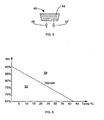
- FIG. 6 illustrates the histogram, for the particular embodiment, of the appearance of condensation impairing the hand-held barcode reader's 30 operation as a function of the relative humidity (RH) and ambient temperature when the barcode reader 30 is taken from an environment having a temperature of -30° C.
- the numeral 52 represents the region where there is no condensation or where the condensation is light enough so as not to interfere with the hand-held barcode reader's 40 operation, while numeral 54 indicates the region where the condensation renders the barcode reader 30 non-functional.
- the heater wire 44 may be embedded within the window assembly 40 by techniques other than lamination, such as being cast in situ so as to be below the surfaces 48, 49.
Landscapes
- Physics & Mathematics (AREA)
- Engineering & Computer Science (AREA)
- Electromagnetism (AREA)
- General Physics & Mathematics (AREA)
- Toxicology (AREA)
- General Health & Medical Sciences (AREA)
- Artificial Intelligence (AREA)
- Computer Vision & Pattern Recognition (AREA)
- Health & Medical Sciences (AREA)
- Theoretical Computer Science (AREA)
- Control Of Resistance Heating (AREA)
- Mechanical Optical Scanning Systems (AREA)
- Resistance Heating (AREA)
- Facsimile Scanning Arrangements (AREA)
- Facsimile Heads (AREA)
- Glass Compositions (AREA)
- Devices For Indicating Variable Information By Combining Individual Elements (AREA)
Claims (18)
- Optischer Scanner (30) umfassend:- Komponenten (33) zum Erzeugen eines scannenden Laserstrahls (20),- einer Fensteranordnung (40) mit:dadurch gekennzeichnet, dass- einem lichtdurchlässigen Feld (42, 43), das dazu ausgebildet ist, den scannenden Laserstrahl zu empfangen und durchzulassen, und- einem Heizdraht (44), der innerhalb des Feldumrisses enthalten ist und Anschlussteile (46, 47) zum Anschließen einer Energiequelle aufweist,- das lichtdurchlässige Feld (42, 43) ein Paar entgegengesetzt gerichtete, ebene Flächen (48, 49) aufweist, die parallel zueinander sind, durch welche Flächen der Laserstrahl zu einem Barcode geleitet wird und eine Reflexion von dem Barcode empfangen wird,- der Heizdraht (44) in einer Ebene des lichtdurchlässigen Feldes (42, 43), parallel zu den Flächen gemessen, eine Breite hat, die geringer ist als eine Breite eines minimal zulässigen Elements in einem Barcode, und- der Heizdraht (44) zwischen den parallelen Flächen (48, 49) des lichtdurchlässigen Feldes (42, 43) eingebettet ist.
- Optischer Scanner (30) nach Anspruch 1, bei dem das lichtdurchlässige Feld aus einem Paar optisch durchlässiger Elemente (42, 43), die nebeneinandergesetzt sind, geformt ist, und von denen jedes ein Paar entgegengesetzt gerichtete, ebene, parallele Flächen (48, 49) hat und der Heizdraht (44) sich zwischen einem einander gegenüberliegenden Flächenpaar (48, 49) der optisch lichtdurchlässigen Elemente (42, 43) befindet.
- Optischer Scanner (30) nach Anspruch 2, bei dem die optisch lichtdurchlässigen Elemente (42, 43) gegossene, rote Acryltafeln sind.
- Optischer Scanner (30) nach Anspruch 1, bei dem die Fensteranordnung (40) des optischen Scanners eine spektrale Transmission von maximal 1 % für Wellenlängen zwischen 450 nm und 575 nm, maximal 10 % für Wellenlängen zwischen 576 nm und 600 nm, 50 % für eine Wellenlänge von 625 nm und minimal 88 % für Wellenlängen zwischen 670 nm und 700 nm hat.
- Optischer Scanner (30) nach Anspruch 1, bei dem die Dimension des Heizdrahts (44) kleiner ist als 0,13 mm (0,005 Inch).
- Optischer Scanner (30) nach Anspruch 1, bei dem der Heizdraht (44) in dem lichtdurchlässigen Feld (42, 43) schlangenartig angeordnet ist.
- Optischer Scanner (30) nach Anspruch 1, bei dem die Dimension des Heizdrahts (44) kleiner ist als 50 % einer minimal zulässigen Breite eines Elements in einem Barcode.
- Optischer Scanner (30) nach Anspruch 1, bei dem die Dimension des Heizdrahts (44) kleiner ist als 20 % einer minimal zulässigen Breite eines Elements eines Barcodes.
- Optischer Scanner (30) nach Anspruch 1, bei dem der Heizdraht (44) schlangenartig, mit Umkehrungen des Heizdrahts (44) an den Randbereichen des lichtdurchlässigen Feldes (42, 43) ausgelegt ist.
- Optischer Scanner (30) nach Anspruch 1, bei dem die Anschlussteile sich über den Umriss des lichtdurchlässigen Feldes (42, 43) hinaus erstrecken.
- Optischer Scanner (30) nach einem der voranstehenden Ansprüche, ferner umfassend:- ein Gehäuse (32), wobei die Fensteranordnung (40) dazu ausgebildet ist, den scannenden Laserstrahl (20) zwischen einem Inneren des Gehäuses (32) und einem aus mehreren Elementen gebildeten Barcode (10) zu leiten, wobei der Heizdraht (44) in einem Paar von Anschlüssen (46, 47), die mit einer Energiequelle (35) elektrisch verbunden sind, in dem Gehäuse (32) endet, und wobei der Heizdraht (44) zwischen den parallelen Flächen (48, 49) in wärmeleitender Anordnung eingefügt ist, und- einen Schalter (34), der dazu betreibbar ist, die Energiequelle (35) mit dem Heizdraht (44) zu verbinden.
- Optischer Scanner nach Anspruch 11, bei dem der Schalter (34) einen mit dem Heizdraht (44) verbundenen Thermostat (36) zum Beibehalten der optischen Scanneinrichtung oberhalb eines vorbestimmten Werts umfasst.
- Optischer Scanner nach Anspruch 12, bei dem sich der Thermostat (36) an einer Außenfläche des Gehäuses (32) befindet.
- Optischer Scanner nach Anspruch 11, bei dem das Element eine kleinstzulässige Breite von 0,13 mm (0,005 Inch) aufweist und der Heizdraht (44) einen Durchmesser in der Größenordnung von 0,029 mm (0,0009 Inch) hat.
- Optischer Scanner nach Anspruch 11, bei dem das Feld aus einem Paar optischer Elemente (42, 43) geformt ist, die nebeneinander angeordnet sind, und der Heizdraht (44) sich zwischen den einander gegenüberliegenden Flächen (48, 49) befindet.
- Verfahren zum Formen eines Fensters für einen optischen Scanner gemäß einem der Ansprüche 1-15, umfassend die Schritte:- Einfügen eines Heizdrahts (44) zwischen einem Paar optisch durchlässiger Elemente (42, 43), von denen jedes ein Paar entgegengesetzt gerichteter ebener Flächen (48, 49) besitzt, die den Heizdraht (44) halten, und- Aufbringen einer Druckkraft auf die Elemente (42, 43), um den Draht (44) zusammenzudrücken, während die ebenen Flächen (48, 49) parallel gehalten werden.
- Verfahren nach Anspruch 16, wobei der Draht (44) auf einer flexiblen Folie aufgebracht ist und die Folie durch einen drucksensitiven Kleber befestigt wird.
- Verfahren nach Anspruch 17 beinhaltend den Schritt des Aufbringens der Druckkraft unter Vakuum, um Luft zwischen den Elementen (42, 43) zu entfernen.
Applications Claiming Priority (2)
| Application Number | Priority Date | Filing Date | Title |
|---|---|---|---|
| US10/421,936 US7059530B2 (en) | 2003-04-24 | 2003-04-24 | Heated protective window for an optical scanning device |
| PCT/CA2004/000611 WO2004095356A1 (en) | 2003-04-24 | 2004-04-26 | Heated protective window for an optical scanning device |
Publications (2)
| Publication Number | Publication Date |
|---|---|
| EP1616285A1 EP1616285A1 (de) | 2006-01-18 |
| EP1616285B1 true EP1616285B1 (de) | 2009-12-09 |
Family
ID=33298759
Family Applications (1)
| Application Number | Title | Priority Date | Filing Date |
|---|---|---|---|
| EP04729389A Expired - Lifetime EP1616285B1 (de) | 2003-04-24 | 2004-04-26 | Geheiztes schützendes fenster für einen optischen abtaster |
Country Status (7)
| Country | Link |
|---|---|
| US (1) | US7059530B2 (de) |
| EP (1) | EP1616285B1 (de) |
| CN (2) | CN101630358A (de) |
| AT (1) | ATE451659T1 (de) |
| CA (1) | CA2523155C (de) |
| DE (1) | DE602004024514D1 (de) |
| WO (1) | WO2004095356A1 (de) |
Families Citing this family (11)
| Publication number | Priority date | Publication date | Assignee | Title |
|---|---|---|---|---|
| US7798411B2 (en) | 2003-04-24 | 2010-09-21 | Psion Teklogix Inc. | Heated protective window for an optical scanning device |
| JP4187672B2 (ja) * | 2004-03-05 | 2008-11-26 | シャープ株式会社 | 光ビーム走査ユニット及び画像形成装置 |
| US8550355B2 (en) * | 2005-06-30 | 2013-10-08 | Symbol Technologies, Inc. | Anti-condensation optical device |
| US7497383B2 (en) * | 2005-08-26 | 2009-03-03 | Symbol Technologies, Inc. | Resisting condensation formation in electro-optical readers |
| DE102006054492C5 (de) * | 2006-11-18 | 2019-05-23 | Leuze Electronic Gmbh & Co. Kg | Barcodelesegerät |
| ES2799123T3 (es) | 2013-12-17 | 2020-12-14 | Eos Gmbh Electro Optical Systems | Sistema de impresión láser |
| BR112018003132B1 (pt) * | 2015-08-19 | 2022-12-20 | Diebold Nixdorf, Incorporated | Invólucro para dispositivo óptico |
| US10156634B2 (en) | 2015-08-24 | 2018-12-18 | The Chamberlain Group, Inc. | Object detection system |
| JP6559562B2 (ja) | 2015-12-21 | 2019-08-14 | 株式会社日立エルジーデータストレージ | 走査型画像表示装置 |
| EP3211377B1 (de) * | 2016-02-29 | 2018-01-31 | Sick Ag | Sensor und verfahren zum heizen eines sensors |
| US10823879B2 (en) | 2018-07-27 | 2020-11-03 | The Chamberlain Group, Inc. | Obstacle detection systems and methods |
Family Cites Families (5)
| Publication number | Priority date | Publication date | Assignee | Title |
|---|---|---|---|---|
| US5508505A (en) * | 1994-10-31 | 1996-04-16 | Psc Inc | Holder for handheld portable bar code scanner |
| US5729003A (en) | 1995-12-27 | 1998-03-17 | Intermec Corporation | Apparatus for preventing formation of condensation on an electrooptical scanner window |
| US7077328B2 (en) * | 1998-07-31 | 2006-07-18 | Abbott Laboratories | Analyte test instrument system including data management system |
| US6321990B1 (en) | 1998-08-05 | 2001-11-27 | Symbol Technologies, Inc. | Scanner with shock-absorbing canopy overmolded with linear of housing |
| US6612493B1 (en) * | 1999-05-27 | 2003-09-02 | Symbol Technologies, Inc. | Optical scanner including a thermostatically controlled heater module or hermatic seal to prevent internal condensation |
-
2003
- 2003-04-24 US US10/421,936 patent/US7059530B2/en not_active Expired - Lifetime
-
2004
- 2004-04-26 EP EP04729389A patent/EP1616285B1/de not_active Expired - Lifetime
- 2004-04-26 AT AT04729389T patent/ATE451659T1/de not_active IP Right Cessation
- 2004-04-26 DE DE602004024514T patent/DE602004024514D1/de not_active Expired - Lifetime
- 2004-04-26 WO PCT/CA2004/000611 patent/WO2004095356A1/en not_active Ceased
- 2004-04-26 CN CN200910164046A patent/CN101630358A/zh active Pending
- 2004-04-26 CA CA2523155A patent/CA2523155C/en not_active Expired - Lifetime
- 2004-04-26 CN CNB200480012938XA patent/CN100547601C/zh not_active Expired - Lifetime
Also Published As
| Publication number | Publication date |
|---|---|
| WO2004095356A1 (en) | 2004-11-04 |
| US7059530B2 (en) | 2006-06-13 |
| DE602004024514D1 (de) | 2010-01-21 |
| EP1616285A1 (de) | 2006-01-18 |
| CN101630358A (zh) | 2010-01-20 |
| CA2523155A1 (en) | 2004-11-04 |
| US20040212861A1 (en) | 2004-10-28 |
| ATE451659T1 (de) | 2009-12-15 |
| CN1788271A (zh) | 2006-06-14 |
| CN100547601C (zh) | 2009-10-07 |
| CA2523155C (en) | 2014-10-07 |
Similar Documents
| Publication | Publication Date | Title |
|---|---|---|
| CA2508602C (en) | Optical code reader having variable depth of field | |
| CA2591147C (en) | Heated protective window for an optical scanning device | |
| JP3698794B2 (ja) | 光学スキャナ | |
| US5729003A (en) | Apparatus for preventing formation of condensation on an electrooptical scanner window | |
| KR100277272B1 (ko) | 확장 초점깊이를 가진 광학스캔너 및 확장 초점깊이를 가지고 주사하는 방법 | |
| EP1616285B1 (de) | Geheiztes schützendes fenster für einen optischen abtaster | |
| US6415982B2 (en) | Triggered data collector and data transmitter | |
| US9297900B2 (en) | Code symbol reading system having adjustable object detection | |
| US6098887A (en) | Optical focusing device and method | |
| JP3272600B2 (ja) | データシンボル読み取り装置 | |
| US5923021A (en) | Light collection systems in electro-optical readers | |
| US6612493B1 (en) | Optical scanner including a thermostatically controlled heater module or hermatic seal to prevent internal condensation | |
| US6568597B2 (en) | Scanning system with adjustable optical characteristics | |
| EP0575894B1 (de) | Rückreflektierendabtastvorrichtung mit von Sammeloptik freiem Rückweg | |
| EP1184803B1 (de) | Elektro-optische Abtastvorrichtung mit einstückigem oszillierenden Fokussier-/Lesekopf | |
| EP2572315B1 (de) | Fokuseinstellung mit einer flüssigkristallvorrichtung bei einem bildgebungsscanner | |
| CN109424871B (zh) | 用于条码扫描器的照明器 | |
| US7007848B2 (en) | Arrangement for generating asymmetrical green laser beam | |
| US7387248B2 (en) | Scan motor | |
| EP1854045B1 (de) | Scanmodul | |
| US5798515A (en) | Optical scanner with fast zoom capability and scanning system | |
| JP2009508145A (ja) | 集光光学素子を有する射出窓を含む電気光学スキャナ | |
| US6905068B2 (en) | Focusing arrangement and method in electro-optical readers | |
| US5949068A (en) | Optical reader for scanning optical indicia by way of varying object distance | |
| JP2725634B2 (ja) | 光学情報読取装置 |
Legal Events
| Date | Code | Title | Description |
|---|---|---|---|
| PUAI | Public reference made under article 153(3) epc to a published international application that has entered the european phase |
Free format text: ORIGINAL CODE: 0009012 |
|
| 17P | Request for examination filed |
Effective date: 20051027 |
|
| AK | Designated contracting states |
Kind code of ref document: A1 Designated state(s): AT BE BG CH CY CZ DE DK EE ES FI FR GB GR HU IE IT LI LU MC NL PL PT RO SE SI SK TR |
|
| AX | Request for extension of the european patent |
Extension state: AL HR LT LV MK |
|
| DAX | Request for extension of the european patent (deleted) | ||
| 17Q | First examination report despatched |
Effective date: 20071217 |
|
| GRAP | Despatch of communication of intention to grant a patent |
Free format text: ORIGINAL CODE: EPIDOSNIGR1 |
|
| GRAS | Grant fee paid |
Free format text: ORIGINAL CODE: EPIDOSNIGR3 |
|
| GRAA | (expected) grant |
Free format text: ORIGINAL CODE: 0009210 |
|
| AK | Designated contracting states |
Kind code of ref document: B1 Designated state(s): AT BE BG CH CY CZ DE DK EE ES FI FR GB GR HU IE IT LI LU MC NL PL PT RO SE SI SK TR |
|
| REG | Reference to a national code |
Ref country code: GB Ref legal event code: FG4D |
|
| REG | Reference to a national code |
Ref country code: CH Ref legal event code: EP |
|
| REG | Reference to a national code |
Ref country code: IE Ref legal event code: FG4D |
|
| REF | Corresponds to: |
Ref document number: 602004024514 Country of ref document: DE Date of ref document: 20100121 Kind code of ref document: P |
|
| REG | Reference to a national code |
Ref country code: DE Ref legal event code: R096 Ref document number: 602004024514 Country of ref document: DE Effective date: 20100121 |
|
| REG | Reference to a national code |
Ref country code: NL Ref legal event code: VDEP Effective date: 20091209 |
|
| PG25 | Lapsed in a contracting state [announced via postgrant information from national office to epo] |
Ref country code: FI Free format text: LAPSE BECAUSE OF FAILURE TO SUBMIT A TRANSLATION OF THE DESCRIPTION OR TO PAY THE FEE WITHIN THE PRESCRIBED TIME-LIMIT Effective date: 20091209 Ref country code: SE Free format text: LAPSE BECAUSE OF FAILURE TO SUBMIT A TRANSLATION OF THE DESCRIPTION OR TO PAY THE FEE WITHIN THE PRESCRIBED TIME-LIMIT Effective date: 20091209 |
|
| PG25 | Lapsed in a contracting state [announced via postgrant information from national office to epo] |
Ref country code: SI Free format text: LAPSE BECAUSE OF FAILURE TO SUBMIT A TRANSLATION OF THE DESCRIPTION OR TO PAY THE FEE WITHIN THE PRESCRIBED TIME-LIMIT Effective date: 20091209 Ref country code: PL Free format text: LAPSE BECAUSE OF FAILURE TO SUBMIT A TRANSLATION OF THE DESCRIPTION OR TO PAY THE FEE WITHIN THE PRESCRIBED TIME-LIMIT Effective date: 20091209 |
|
| PG25 | Lapsed in a contracting state [announced via postgrant information from national office to epo] |
Ref country code: AT Free format text: LAPSE BECAUSE OF FAILURE TO SUBMIT A TRANSLATION OF THE DESCRIPTION OR TO PAY THE FEE WITHIN THE PRESCRIBED TIME-LIMIT Effective date: 20091209 |
|
| PG25 | Lapsed in a contracting state [announced via postgrant information from national office to epo] |
Ref country code: NL Free format text: LAPSE BECAUSE OF FAILURE TO SUBMIT A TRANSLATION OF THE DESCRIPTION OR TO PAY THE FEE WITHIN THE PRESCRIBED TIME-LIMIT Effective date: 20091209 Ref country code: PT Free format text: LAPSE BECAUSE OF FAILURE TO SUBMIT A TRANSLATION OF THE DESCRIPTION OR TO PAY THE FEE WITHIN THE PRESCRIBED TIME-LIMIT Effective date: 20100409 Ref country code: RO Free format text: LAPSE BECAUSE OF FAILURE TO SUBMIT A TRANSLATION OF THE DESCRIPTION OR TO PAY THE FEE WITHIN THE PRESCRIBED TIME-LIMIT Effective date: 20091209 Ref country code: BG Free format text: LAPSE BECAUSE OF FAILURE TO SUBMIT A TRANSLATION OF THE DESCRIPTION OR TO PAY THE FEE WITHIN THE PRESCRIBED TIME-LIMIT Effective date: 20100309 Ref country code: ES Free format text: LAPSE BECAUSE OF FAILURE TO SUBMIT A TRANSLATION OF THE DESCRIPTION OR TO PAY THE FEE WITHIN THE PRESCRIBED TIME-LIMIT Effective date: 20100320 Ref country code: EE Free format text: LAPSE BECAUSE OF FAILURE TO SUBMIT A TRANSLATION OF THE DESCRIPTION OR TO PAY THE FEE WITHIN THE PRESCRIBED TIME-LIMIT Effective date: 20091209 |
|
| PG25 | Lapsed in a contracting state [announced via postgrant information from national office to epo] |
Ref country code: CZ Free format text: LAPSE BECAUSE OF FAILURE TO SUBMIT A TRANSLATION OF THE DESCRIPTION OR TO PAY THE FEE WITHIN THE PRESCRIBED TIME-LIMIT Effective date: 20091209 Ref country code: BE Free format text: LAPSE BECAUSE OF FAILURE TO SUBMIT A TRANSLATION OF THE DESCRIPTION OR TO PAY THE FEE WITHIN THE PRESCRIBED TIME-LIMIT Effective date: 20091209 Ref country code: SK Free format text: LAPSE BECAUSE OF FAILURE TO SUBMIT A TRANSLATION OF THE DESCRIPTION OR TO PAY THE FEE WITHIN THE PRESCRIBED TIME-LIMIT Effective date: 20091209 |
|
| PLBE | No opposition filed within time limit |
Free format text: ORIGINAL CODE: 0009261 |
|
| STAA | Information on the status of an ep patent application or granted ep patent |
Free format text: STATUS: NO OPPOSITION FILED WITHIN TIME LIMIT |
|
| PG25 | Lapsed in a contracting state [announced via postgrant information from national office to epo] |
Ref country code: GR Free format text: LAPSE BECAUSE OF FAILURE TO SUBMIT A TRANSLATION OF THE DESCRIPTION OR TO PAY THE FEE WITHIN THE PRESCRIBED TIME-LIMIT Effective date: 20100310 Ref country code: CY Free format text: LAPSE BECAUSE OF FAILURE TO SUBMIT A TRANSLATION OF THE DESCRIPTION OR TO PAY THE FEE WITHIN THE PRESCRIBED TIME-LIMIT Effective date: 20091209 |
|
| 26N | No opposition filed |
Effective date: 20100910 |
|
| PG25 | Lapsed in a contracting state [announced via postgrant information from national office to epo] |
Ref country code: MC Free format text: LAPSE BECAUSE OF NON-PAYMENT OF DUE FEES Effective date: 20100430 |
|
| REG | Reference to a national code |
Ref country code: CH Ref legal event code: PL |
|
| REG | Reference to a national code |
Ref country code: DE Ref legal event code: R097 Ref document number: 602004024514 Country of ref document: DE Effective date: 20100910 |
|
| PG25 | Lapsed in a contracting state [announced via postgrant information from national office to epo] |
Ref country code: IE Free format text: LAPSE BECAUSE OF NON-PAYMENT OF DUE FEES Effective date: 20100426 Ref country code: DK Free format text: LAPSE BECAUSE OF FAILURE TO SUBMIT A TRANSLATION OF THE DESCRIPTION OR TO PAY THE FEE WITHIN THE PRESCRIBED TIME-LIMIT Effective date: 20091209 |
|
| PG25 | Lapsed in a contracting state [announced via postgrant information from national office to epo] |
Ref country code: LI Free format text: LAPSE BECAUSE OF NON-PAYMENT OF DUE FEES Effective date: 20100430 Ref country code: CH Free format text: LAPSE BECAUSE OF NON-PAYMENT OF DUE FEES Effective date: 20100430 |
|
| PG25 | Lapsed in a contracting state [announced via postgrant information from national office to epo] |
Ref country code: IT Free format text: LAPSE BECAUSE OF FAILURE TO SUBMIT A TRANSLATION OF THE DESCRIPTION OR TO PAY THE FEE WITHIN THE PRESCRIBED TIME-LIMIT Effective date: 20091209 |
|
| PG25 | Lapsed in a contracting state [announced via postgrant information from national office to epo] |
Ref country code: LU Free format text: LAPSE BECAUSE OF NON-PAYMENT OF DUE FEES Effective date: 20100426 Ref country code: HU Free format text: LAPSE BECAUSE OF FAILURE TO SUBMIT A TRANSLATION OF THE DESCRIPTION OR TO PAY THE FEE WITHIN THE PRESCRIBED TIME-LIMIT Effective date: 20100610 |
|
| PG25 | Lapsed in a contracting state [announced via postgrant information from national office to epo] |
Ref country code: TR Free format text: LAPSE BECAUSE OF FAILURE TO SUBMIT A TRANSLATION OF THE DESCRIPTION OR TO PAY THE FEE WITHIN THE PRESCRIBED TIME-LIMIT Effective date: 20091209 |
|
| REG | Reference to a national code |
Ref country code: DE Ref legal event code: R082 Ref document number: 602004024514 Country of ref document: DE Representative=s name: , |
|
| REG | Reference to a national code |
Ref country code: DE Ref legal event code: R081 Ref document number: 602004024514 Country of ref document: DE Owner name: PSION INC., CA Free format text: FORMER OWNER: PSION TEKLOGIX INC., MISSISSAUGA, CA Effective date: 20130801 Ref country code: DE Ref legal event code: R082 Ref document number: 602004024514 Country of ref document: DE Representative=s name: LKGLOBAL | LORENZ & KOPF PARTG MBB PATENTANWAE, DE Effective date: 20130402 Ref country code: DE Ref legal event code: R082 Ref document number: 602004024514 Country of ref document: DE Representative=s name: SCHUMACHER & WILLSAU PATENTANWALTSGESELLSCHAFT, DE Effective date: 20130402 Ref country code: DE Ref legal event code: R081 Ref document number: 602004024514 Country of ref document: DE Owner name: PSION INC., MISSISSAUGA, CA Free format text: FORMER OWNER: PSION TEKLOGIX INC., MISSISSAUGA, ONTARIO, CA Effective date: 20130801 Ref country code: DE Ref legal event code: R082 Ref document number: 602004024514 Country of ref document: DE Representative=s name: KOPF, KORBINIAN, DIPL.-ING.UNIV., MA, DE Effective date: 20130402 Ref country code: DE Ref legal event code: R082 Ref document number: 602004024514 Country of ref document: DE Representative=s name: LKGLOBAL LORENZ UND KOPF PATENTANWALT, ATTORNE, DE Effective date: 20130402 Ref country code: DE Ref legal event code: R082 Ref document number: 602004024514 Country of ref document: DE Representative=s name: LKGLOBAL LORENZ UND KOPF PATENTANWALT, ATTORNE, DE Effective date: 20130801 |
|
| REG | Reference to a national code |
Ref country code: FR Ref legal event code: CD Owner name: PSION INC., CA Effective date: 20130903 |
|
| REG | Reference to a national code |
Ref country code: FR Ref legal event code: PLFP Year of fee payment: 13 |
|
| REG | Reference to a national code |
Ref country code: DE Ref legal event code: R082 Ref document number: 602004024514 Country of ref document: DE Representative=s name: LKGLOBAL | LORENZ & KOPF PARTG MBB PATENTANWAE, DE Ref country code: DE Ref legal event code: R082 Ref document number: 602004024514 Country of ref document: DE Representative=s name: KOPF, KORBINIAN, DIPL.-ING.UNIV., MA, DE Ref country code: DE Ref legal event code: R082 Ref document number: 602004024514 Country of ref document: DE Representative=s name: LKGLOBAL LORENZ UND KOPF PATENTANWALT, ATTORNE, DE |
|
| REG | Reference to a national code |
Ref country code: FR Ref legal event code: PLFP Year of fee payment: 14 |
|
| REG | Reference to a national code |
Ref country code: DE Ref legal event code: R082 Ref document number: 602004024514 Country of ref document: DE Representative=s name: LKGLOBAL | LORENZ & KOPF PARTG MBB PATENTANWAE, DE Ref country code: DE Ref legal event code: R082 Ref document number: 602004024514 Country of ref document: DE Representative=s name: LKGLOBAL LORENZ UND KOPF PATENTANWALT, ATTORNE, DE |
|
| REG | Reference to a national code |
Ref country code: FR Ref legal event code: PLFP Year of fee payment: 15 |
|
| PGFP | Annual fee paid to national office [announced via postgrant information from national office to epo] |
Ref country code: FR Payment date: 20230321 Year of fee payment: 20 |
|
| PGFP | Annual fee paid to national office [announced via postgrant information from national office to epo] |
Ref country code: GB Payment date: 20230321 Year of fee payment: 20 |
|
| P01 | Opt-out of the competence of the unified patent court (upc) registered |
Effective date: 20230411 |
|
| PGFP | Annual fee paid to national office [announced via postgrant information from national office to epo] |
Ref country code: DE Payment date: 20230321 Year of fee payment: 20 |
|
| REG | Reference to a national code |
Ref country code: DE Ref legal event code: R071 Ref document number: 602004024514 Country of ref document: DE |
|
| REG | Reference to a national code |
Ref country code: GB Ref legal event code: PE20 Expiry date: 20240425 |
|
| PG25 | Lapsed in a contracting state [announced via postgrant information from national office to epo] |
Ref country code: GB Free format text: LAPSE BECAUSE OF EXPIRATION OF PROTECTION Effective date: 20240425 |
|
| PG25 | Lapsed in a contracting state [announced via postgrant information from national office to epo] |
Ref country code: GB Free format text: LAPSE BECAUSE OF EXPIRATION OF PROTECTION Effective date: 20240425 |