EP1616205B1 - Passives avioniksystem und verfahren zur detektion von turbulenzen in wolkenfreier luft - Google Patents
Passives avioniksystem und verfahren zur detektion von turbulenzen in wolkenfreier luft Download PDFInfo
- Publication number
- EP1616205B1 EP1616205B1 EP04704400.3A EP04704400A EP1616205B1 EP 1616205 B1 EP1616205 B1 EP 1616205B1 EP 04704400 A EP04704400 A EP 04704400A EP 1616205 B1 EP1616205 B1 EP 1616205B1
- Authority
- EP
- European Patent Office
- Prior art keywords
- cat
- data samples
- digital data
- aircraft
- processor
- Prior art date
- Legal status (The legal status is an assumption and is not a legal conclusion. Google has not performed a legal analysis and makes no representation as to the accuracy of the status listed.)
- Expired - Lifetime
Links
- 238000000034 method Methods 0.000 title claims abstract description 24
- 238000001514 detection method Methods 0.000 title claims abstract description 17
- 230000000694 effects Effects 0.000 claims abstract description 37
- 238000012545 processing Methods 0.000 claims abstract description 23
- 230000005670 electromagnetic radiation Effects 0.000 claims abstract description 17
- 230000015654 memory Effects 0.000 claims description 25
- 239000000872 buffer Substances 0.000 claims description 16
- 230000008569 process Effects 0.000 claims description 16
- 239000002131 composite material Substances 0.000 claims description 12
- 230000005855 radiation Effects 0.000 claims description 11
- 230000005684 electric field Effects 0.000 claims description 6
- 238000005070 sampling Methods 0.000 claims description 5
- 230000006870 function Effects 0.000 claims description 4
- 230000001131 transforming effect Effects 0.000 claims 1
- 239000012723 sample buffer Substances 0.000 description 19
- 239000000523 sample Substances 0.000 description 10
- 230000000875 corresponding effect Effects 0.000 description 7
- 238000005259 measurement Methods 0.000 description 5
- 238000001556 precipitation Methods 0.000 description 5
- 230000002596 correlated effect Effects 0.000 description 4
- 238000013507 mapping Methods 0.000 description 3
- 208000027418 Wounds and injury Diseases 0.000 description 2
- 238000013459 approach Methods 0.000 description 2
- 238000004364 calculation method Methods 0.000 description 2
- 230000006378 damage Effects 0.000 description 2
- 238000010586 diagram Methods 0.000 description 2
- 230000009977 dual effect Effects 0.000 description 2
- 238000001914 filtration Methods 0.000 description 2
- 208000014674 injury Diseases 0.000 description 2
- 238000012544 monitoring process Methods 0.000 description 2
- 238000007792 addition Methods 0.000 description 1
- 230000000295 complement effect Effects 0.000 description 1
- 238000012217 deletion Methods 0.000 description 1
- 230000037430 deletion Effects 0.000 description 1
- 238000013461 design Methods 0.000 description 1
- 230000002708 enhancing effect Effects 0.000 description 1
- 239000011521 glass Substances 0.000 description 1
- 230000006872 improvement Effects 0.000 description 1
- 238000012986 modification Methods 0.000 description 1
- 230000004048 modification Effects 0.000 description 1
- 238000011160 research Methods 0.000 description 1
- 230000009466 transformation Effects 0.000 description 1
Images

Classifications
-
- G—PHYSICS
- G01—MEASURING; TESTING
- G01S—RADIO DIRECTION-FINDING; RADIO NAVIGATION; DETERMINING DISTANCE OR VELOCITY BY USE OF RADIO WAVES; LOCATING OR PRESENCE-DETECTING BY USE OF THE REFLECTION OR RERADIATION OF RADIO WAVES; ANALOGOUS ARRANGEMENTS USING OTHER WAVES
- G01S11/00—Systems for determining distance or velocity not using reflection or reradiation
- G01S11/02—Systems for determining distance or velocity not using reflection or reradiation using radio waves
- G01S11/06—Systems for determining distance or velocity not using reflection or reradiation using radio waves using intensity measurements
-
- G—PHYSICS
- G01—MEASURING; TESTING
- G01S—RADIO DIRECTION-FINDING; RADIO NAVIGATION; DETERMINING DISTANCE OR VELOCITY BY USE OF RADIO WAVES; LOCATING OR PRESENCE-DETECTING BY USE OF THE REFLECTION OR RERADIATION OF RADIO WAVES; ANALOGOUS ARRANGEMENTS USING OTHER WAVES
- G01S13/00—Systems using the reflection or reradiation of radio waves, e.g. radar systems; Analogous systems using reflection or reradiation of waves whose nature or wavelength is irrelevant or unspecified
- G01S13/88—Radar or analogous systems specially adapted for specific applications
- G01S13/95—Radar or analogous systems specially adapted for specific applications for meteorological use
- G01S13/953—Radar or analogous systems specially adapted for specific applications for meteorological use mounted on aircraft
-
- G—PHYSICS
- G01—MEASURING; TESTING
- G01W—METEOROLOGY
- G01W1/00—Meteorology
- G01W2001/003—Clear air turbulence detection or forecasting, e.g. for aircrafts
-
- Y—GENERAL TAGGING OF NEW TECHNOLOGICAL DEVELOPMENTS; GENERAL TAGGING OF CROSS-SECTIONAL TECHNOLOGIES SPANNING OVER SEVERAL SECTIONS OF THE IPC; TECHNICAL SUBJECTS COVERED BY FORMER USPC CROSS-REFERENCE ART COLLECTIONS [XRACs] AND DIGESTS
- Y02—TECHNOLOGIES OR APPLICATIONS FOR MITIGATION OR ADAPTATION AGAINST CLIMATE CHANGE
- Y02A—TECHNOLOGIES FOR ADAPTATION TO CLIMATE CHANGE
- Y02A90/00—Technologies having an indirect contribution to adaptation to climate change
- Y02A90/10—Information and communication technologies [ICT] supporting adaptation to climate change, e.g. for weather forecasting or climate simulation
Definitions
- the present invention relates to clear air turbulence (CAT) detection systems for aircraft, in general, and more particularly, to a passive CAT detection avionics system and method which receives electromagnetic signals produced by the CAT and processes such received signals with known CAT waveform signatures to identify CAT activity and determine the position thereof with respect to the aircraft.
- CAT clear air turbulence
- Air turbulence is caused by many different atmospheric conditions and may at times be dangerous to aircraft flight. Inclement weather in the form of precipitation may cause damaging air turbulence and thus, should be detected by an aircraft and avoided. For this reason, the Federal Aviation Agency (FAA) requires that weather radars be installed on all commercial aircraft. Airborne weather radars use an active radar element usually mounted in the nose of the aircraft to transmit a radar signal and receive reflections from precipitation within the range of the radar signal. The reflections are processed to detect areas of precipitation which are displayed on a display screen color coded for intensity. Thus, a pilot can view the screen, determine the severity of a storm in the flight path, and make the determination of whether or not to alter the flight path to avoid the storm.
- FAA Federal Aviation Agency
- Another dangerous form of air turbulence arises from the updrafts and downdrafts which create lightning conditions. These conditions generally arise ahead or on the edge of any associated precipitation. Accordingly, weather radar systems may not detect this form of air turbulence until it is too late to avoid it.
- lightning detection instruments such as the Stormscope® weather mapping system manufactured by Goodrich Avionic Systems Inc. under a number of different models, for example, can detect the electromagnetic energy produced by the lightning activity and map the location thereof on a display viewable by the pilot.
- a complementary avionics system combining both weather radar and lightning detection should provide a viable weather mapping of any precipitation or storm related activity.
- CAT avionics system which can detect CAT at sufficient distances from the aircraft to permit the pilot to alter course and avoid the turbulence, or at least provide adequate warning for the passengers to fasten their safety belts as protection against personal injury. Such a system would result in a substantial improvement to flight safety.
- CAT passive clear air turbulence
- CAT clear air turbulence
- FIG. 1 is a block diagram schematic of a CAT detection system suitable for embodying the broad principles of the present invention.
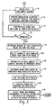
- FIG. 2 depicts an exemplary flowchart suitable for use in programming the CAT detection system embodiment of FIG. 1 in accordance with the principles of the present invention.
- the inventors have recognized that while CAT occurs under tranquil and cloudless conditions, the resulting strong updrafts, downdrafts and other components of turbulence produce electromagnetic energy in the form of radiation which may be monitored. Research has indicated that electromagnetic energy builds up and discharges during CAT activity, thus producing radiation pulses that may have cycles many minutes long. Accordingly, the discharges of the built up energy may be monitored from as far away as 400 nautical miles (nmi), for example.
- the inventors have also recognized that the pulsed electromagnetic radiation resulting from known areas of CAT may be monitored by a conventional passive antenna on-board an aircraft to collect data on the magnetic and electric component waveforms produced thereby.
- the airspace ahead and surrounding an aircraft may be monitored with a conventional on-board cross-looped and sense antenna, like the antenna from the Stormscope® avionics, model WX1000, for example, which receives electromagnetic radiation and converts it into electrical signals representative of the magnetic and electric components thereof.
- the converted electrical signals may be digitized, time-tagged, and stored.
- the stored data is analyzed by correlating it with predetermined CAT waveform signatures using digital signal processing techniques. The analysis may take into account the pulse shape, pulse polarity, and relative timing of the components of the monitored radiation for detection of CAT activity, and the direction-of-arrival and energy levels for determining position in range and bearing, for example, as will become more evident from the description found herein below.
- FIG. 1 is a block diagram schematic of a CAT detection system 10 suitable for embodying the broad principles of the present invention.
- a cross-looped and sense antenna 12 which may be of the type used in the Stormscope® avionics, model WX-1000, for example, is mounted on-board an aircraft for use, during flight, in monitoring the airspace ahead and surrounding the aircraft for electromagnetic radiation. More specifically, the antenna 12 comprises two antenna loops 14 and 16 arranged perpendicular to one another with one aligned to receive magnetic radiation along the heading of the aircraft, referred to herein as the X magnetic field component, and the other to receive magnetic radiation transverse to the aircraft heading, referred to herein as the Y magnetic field component, for example.
- the antenna 12 further includes an electric field sense element 18 for receiving the electric field component of the electromagnetic radiation, referred to herein as the E field component.
- the antenna 12 converts the received radiation components E, X, and Y into representative electrical analog signals which are output over respectively corresponding signal lines 20, 22, and 24 to amplifiers 26, 28 and 30, respectively.
- Each amplifier 26, 28 and 30 may be a programmable gain amplifier to amplify its respective analog signal by a programmed gain in order to keep the amplified signal level within an acceptable range for analysis.
- each amplifier has gain settings of 1, 2, 5 and 10, but it is understood by all those skilled in the pertinent art that other gain settings are possible.
- the gain setting for each amplifier may be either determined by experimentation and preset manually into the amplifier for operation, or determined from a monitoring of the analysis process during operation; in which case, the gain of an amplifier would be automatically adjusted to maintain the amplified level within an acceptable range for analysis.
- the amplified E, X and Y signals are coupled to inputs of an analog multiplexer circuit 32 over respective signal lines 34, 36 and 38.
- the multiplexer 32 may be a conventional four channel multiplexer with one unused channel, for example.
- a selected input signal of the multiplexer 32 is coupled over signal line 42 to an analog-to-digital converter circuit 40, which may be of the type manufactured by Analog Devices under the model no. AD625, for example.
- the converter 40 is operative to digitize the signal over line 42 into a 16 bit word representative thereof, for example.
- Each digitized word of the converter 40 is supplied to a mass storage memory device 44, which may include one or more sample buffers, over signal lines 46.
- the memory 44 may be a conventional hard disk drive or a high density random access memory, for example, with the capacity to store a predetermined number of digitized samples of each of the signals E, X and Y.
- the sample data memory 44 may store the digitized samples of E, X and Y into respective addressable storage channels for convenient retrieval thereof for processing in a digital signal processor 50, which may be of the type manufactured by Texas Instruments under the model number TMS 320CV31, for example.
- the processor 50 may address each sample buffer of memory 44 to access the stored data samples over address, control and data lines 52.
- two sample buffers are included in memory 44.
- One may be used to store data samples as they are being digitized while the other is accessed by the processor for retrieval of stored data samples for the processing thereof and vice versa.
- the use of dual sample buffers in memory 44 permits continuous storage and processing of data samples by alternating between the two sample buffers.
- the multiplexer 32 and analog-to-digital converter 40 may be integrated on a single "off-the-shelf" printed circuit card which may be of the type manufactured by Measurement Computing under the model or part no. PCI-DAS4020/12, for example.
- the digital signal processor 50 is programmed to analyze the data samples of the three signal components E, X and Y to detect CAT activity and determine the severity and position thereof, preferably in range and bearing in relation to the aircraft.
- CAT radiation pulses when CAT radiation pulses are detected, their corresponding range and bearing signals are provided over signal lines 54 to a display controller 56 which drives a display monitor 58 to display the CAT activity and its position in relation to the aircraft on a display screen 60 thereof, which is viewable by the pilot.
- the display controller 56 and display monitor 58 may be of the type used in the Stormscope avionics, model no. WX-1000, for example.
- information comprising the range and bearing to the CAT along with an indication of the severity thereof may be communicated across an avionics network to a weather radar display or a glass panel multi-functional avionics display, for example, and overlaid or superimposed onto an existing display image.
- a programmed microcontroller or programmable gate array (PGA) 62 may be programmed with the logic to coordinate in a time sequenced manner the operations of the multiplexer 32 over signal lines 64, the analog-to-digital converter 40 over signal lines 66 and the dual sample buffer memory 44 over signal lines 68, for example.
- the PGA 62 may be of the field programmable type manufactured by Xilinx Inc. under model number XC95144XL, for example. In operation, the PGA 62 may control the multiplexer 32 via signal lines 64 to pass each of its input signals E, X and Y sequentially to the output line 42 periodically with a time period of approximately one microsecond, for example.
- each analog signal E, X, and Y is sampled by the multiplexer 32 at one microsecond intervals or at a sampling rate of one megahertz.
- Each signal over line 42 is given time to stabilize by the PGA 62, and then, the converter 40 is controlled via lines 66 to digitize the selected analog sample into a digital word which is presented over signal lines 46.
- the PGA 62 allows for time for the digital word to stabilize on lines 46, then controls via lines 68 the storage thereof into the respective channel assigned to the selected sample.
- each sample buffer of memory 44 is configured to store digital data sample words of each signal E, X and Y over a period of 20 milliseconds, or 20,000 data samples each.
- the other sample buffer previously filled over the preceding 20 milliseconds is accessed by the processor 50 for processing the data samples thereof.
- the PGA 62 may control the storage of data samples into one of the sample buffers and determine when that buffer is filled, then switch to the other sample buffer and control the storage of data samples therein. Once the other sample buffer is filled, the process is repeated.
- the collection of data samples which may be 20,000 data samples for each signal E, X and Y are time tagged utilizing a real time clock which maybe programmed into the PGA 62, for example.
- FIG. 2 depicts an exemplary flowchart for use in programming the digital signal processor 50 to process the data samples stored in the sample buffers of memory 44.
- the program starts execution at block 70 which instructs the processor 50 to access the data samples and corresponding time tag of the filled sample buffer of memory 44 in a sequential data stream starting with the first data sample and ending with the 20,000th data sample.
- a convolution algorithm which includes the characteristics of known CAT waveform signatures embedded therein is called to process the accessed data sample stream to identify a pulse or pulses of the data stream which match a CAT waveform signature to a predetermined degree.
- the convolution algorithm attaches a numerical value to each pulse of a data steam processed thereby.
- the numerical value is representative of a percentage of a match of a pulse in the data sample stream to a CAT waveform signature. For example, if the match is perfect, the algorithm may attach the number 1.0 (100% match); if the pulse is somewhat matching, the algorithm may attach the number 0.5 (50% match) to the pulse; and if there is no match; the algorithm may attach a 0 to the pulse. Those pulses of the data sample stream which have a match above a certain numerical value are identified as candidate pulses of CAT activity and time tagged.
- the samples of the data stream of the E signal may be accessed first and processed sequentially by the convolution algorithm for each E signal CAT waveform signature. This may result in repeated convolutions for each possible waveform signature.
- Each pulse of the E signal data stream that meets the match criteria as described herein above is time tagged and stored. The width, polarity and amplitude of each identified pulse is determined and stored along with the time tag thereof.
- the samples of the data stream of the X signal are accessed and processed by the convolution algorithm in the same manner as the E signal data stream. Those X signal pulses that meet the match criteria are identified and time tagged along with the width and amplitude thereof.
- the samples of the data stream of the Y signal are accessed and processed by the convolution algorithm in the same manner and the identified pulses are time tagged along with the width and amplitudes thereof. It is understood that the order in which the E, X and Y data streams are processed by the convolution algorithm may be changed to that described above without deviating from the broad principles of the present invention.
- the identified pulses are correlated based on the time tags thereof to ensure a pulse match of all three signals. That is, if one of the signals E, X and Y does not have a pulse match at a time substantially close to or within a predetermined time window of a pulse match of the other signals, then the identified pulse may not be considered coming from CAT activity.
- Each pulse that meets the match criteria and time criteria across all of the signals E, X and Y is flagged as a candidate pulse of CAT activity.
- the pulse width and amplitude of each candidate pulse identified from block 72 are compared with predetermined criteria to confirm that such pulses are CAT pulses.
- each confirmed pulse is determined in relation to the heading of the aircraft in block 78 as a function of the amplitudes of the X and Y component pulses thereof. For example, the arctangent of the ratio of the Y pulse amplitude to the X pulse amplitude results in a bearing angle in relation to the heading of the aircraft. Any ambiguity in bearing may be resolved by the polarity of the associated E component pulse or by a relationship of the polarities of the correlated X, Y and E pulses of the CAT activity.
- Each CAT bearing measurement is stored in a memory location correlated to the time tag of its corresponding X, Y and E pulses.
- a select number of data samples of the E signal component and either the X or Y signal component are taken about each confirmed pulse using the time tag thereof as a reference.
- CAT pulses may range from 100 to 400 microseconds in width and that each data sample represents a time interval of one microsecond. So, to ensure that the whole pulse is included, the selected number of samples may comprise around one thousand samples, for example.
- a Fast Fourier Transformation (FFT) may be performed on the selected number of time data samples about each confirmed pulse. The FFT results in 1000 frequency bins for each of the E signal component and the X or Y signal component. From an energy standpoint, 500 of the frequency bins are redundant for each component. Moreover, only frequencies on the order of 100 KHz, ⁇ 50 KHz (40-50 frequency bins) are characteristic of a CAT pulse and therefore, of concern for the determination of range for each confirmed pulse.
- the composite energy of these 40-50 frequency bins is determined for use in calculating range from the aircraft to the confirmed CAT pulse.
- Range is determined based on the presumption that the further the CAT activity is from the aircraft, the further the radiation produced thereby has to travel, thus the weaker the energy of the signal. From this presumption, range for each confirmed pulse may be determined as an inverse function of the composite energy calculated therefor. Also, if the calculated energy for a confirmed pulse is below a predetermined level, the associated pulse may be ignored.
- the range and bearing measurements of each confirmed pulse are correlated based on the time tags thereof. These range and bearing measurements locate the position of the associated CAT activity in relation to the aircraft.
- each range and bearing pair of measurements are supplied to the display controller 50 so that symbols corresponding to the associated CAT activity may be displayed on the screen 60 of the monitor 58 at locations in range and bearing in relation to the aircraft or communicated across the avionics network as noted above.
- An aircraft symbol may appear on the screen 60 so that the pilot may view a map of the CAT activity in relation to the aircraft.
- the program execution may then return to block 70 to repeat the processing for the data samples of the other sample buffer of memory 44. Program execution will also be deviated back to block 70 if no turbulence is detected by the decisional block 76.
- a wait loop may be designed in the program of the digital signal processor 50 to permit it to wait until the other sample buffer is filled before accessing data samples therefrom.
- the processor 50 may process the data samples of one sample buffer and then the other alternately in accordance with the foregoing described processing steps.
Landscapes
- Physics & Mathematics (AREA)
- Engineering & Computer Science (AREA)
- General Physics & Mathematics (AREA)
- Radar, Positioning & Navigation (AREA)
- Remote Sensing (AREA)
- Radar Systems Or Details Thereof (AREA)
Claims (22)
- Passives Höhenwirbelturbulenz- (Clear Air Turbulence - CAT) Erfassungssystem (10) zur Verwendung an Bord eines Flugzeugs, wobei das System Folgendes umfasst:eine Antenne (12) zum Empfang von elektromagnetischer Strahlung und zur Erzeugung von elektrischen Signalen, die die elektromagnetische Strahlung darstellen, undeinen Prozessor (50) zum Verarbeiten der elektrischen Signale mit mindestens einer CAT-Wellenformsignatur, um CAT-Aktivität in Bezug auf das Flugzeug zu erfassen,wobei der Prozessor zur Verarbeitung der elektrischen Signale so ausgebildet ist, dass er elektromagnetische Strahlungsimpulse identifiziert, die mindestens einer CAT-Impulsentladungswellenformsignatur basierend auf vorbestimmten Kriterien entsprechen, um CAT-Aktivität in Bezug auf das Flugzeug zu erfassen.
- System nach Anspruch 1, das eine Digitalisierschaltung (40) zum Digitalisieren der elektrischen Signale mit einer vorbestimmten Rate umfasst, um digitale Datenabtastwerte davon zu erzeugen, und wobei der Prozessor (50) einen digitalen Prozessor umfasst, der die digitalen Datenabtastwerte verarbeitet, um Impulse zu identifizieren, die mindestens einer CAT-Wellenformsignatur basierend auf einem vorgegebenen Kriterium entsprechen, wobei die identifizierten Impulse repräsentativ für CAT-Aktivität sind.
- System nach Anspruch 2, wobei der digitale Prozessor (50) mit einem Faltungsalgorithmus programmiert ist, in dem die mindestens eine CAT-Wellenformsignatur eingebettet ist, und wobei der digitale Prozessor die digitalen Datenabtastwerte mit dem Faltungsalgorithmus verarbeitet, um Impulse zu identifizieren, die der mindestens einen CAT-Wellenformsignatur basierend auf den vorgegebenen Kriterien entsprechen.
- System nach Anspruch 2 oder 3, wobei der digitale Prozessor (50) eine Position jedes identifizierten Impulses in Bezug auf das Flugzeug basierend auf den digitalen Datenabtastwerten des entsprechenden identifizierten Impulses ermittelt.
- System nach einem der vorhergehenden Ansprüche, wobei die Antenne (12) ein Paar Schleifenantennen (14, 16) umfasst, wobei die Schleifenantennen im Wesentlichen senkrecht zueinander angeordnet sind, wobei eine Schleifenantenne (14, 16) des Paars zum Empfangen einer X-Magnetfeldkomponente der elektromagnetischen Strahlung und zum Erzeugen eines dafür repräsentativen elektrischen X-Signals dient und wobei die andere Schleifenantenne (16, 14) des Paars zum Empfang einer Y-Magnetfeldkomponente der elektromagnetischen Strahlung und zum Erzeugen eines dafür repräsentativen elektrischen Y-Signals dient.
- System nach Anspruch 5, wobei die eine Schleifenantenne (14, 16) so ausgerichtet ist, dass sie Magnetfeldstrahlung entlang der Flugrichtung des Flugzeugs empfängt, und die andere Schleifenantenne (16, 14) so ausgerichtet ist, dass sie Magnetfeldstrahlung quer zur Flugrichtung des Flugzeugs empfängt.
- System nach Anspruch 5 oder 6, das Folgendes umfasst: eine Abtastschaltung (32), die mit der Antenne (12) gekoppelt ist, zur Zeitabtastung der elektrischen X- und Y-Signale mit einer vorbestimmten Rate, um Zeitabtastwerte davon zu erzeugen; und eine Digitalisierschaltung (40), die mit der Abtastschaltung gekoppelt ist, um die Zeitabtastwerte der elektrischen X- und Y-Signale jeweils in digitale X- und Y-Datenabtastwerte zu digitalisieren, und wobei der Prozessor (50) einen digitalen Prozessor umfasst, der die digitalen X-Datenabtastwerte verarbeitet, um einen X-Impuls zu identifizieren, der mindestens einer CAT-Wellenformsignatur für das elektrische X-Signal basierend auf einem ersten vorbestimmten Kriterium entspricht, und der die digitalen Y-Datenabtastwerte verarbeitet, um einen Y-Impuls zu identifizieren, der mindestens einer CAT-Wellenformsignatur für das elektrische Y-Signal basierend auf einem zweiten vorbestimmten Kriterium entspricht.
- System nach Anspruch 7, wobei der digitale Prozessor (50) mit einem Faltungsalgorithmus programmiert ist, in dem mindestens eine CAT-Wellenformsignatur für jedes der elektrischen X- und Y-Signale eingebettet ist, und wobei der digitale Prozessor die digitalen X-Datenabtastwerte mit dem Faltungsalgorithmus verarbeitet, um einen X-Impuls zu identifizieren, der mindestens einer CAT-Wellenformsignatur für das elektrische X-Signal basierend auf den ersten vorbestimmten Kriterien entspricht, und wobei der digitale Prozessor die digitalen Y-Datenabtastwerte mit dem Faltungsalgorithmus verarbeitet, um einen Y-Impuls zu identifizieren, der mindestens einer CAT-Wellenformsignatur für das elektrische Y-Signal basierend auf den zweiten vorbestimmten Kriterien entspricht.
- System nach Anspruch 7 oder 8, wobei der digitale Prozessor (50) die identifizierten X- und Y-Impulse als zu der gleichen CAT-Aktivität zugehörig korreliert und eine Peilung der CAT-Aktivität in Bezug auf das Flugzeug basierend auf einer Funktion von Amplituden der identifizierten X- und Y-Impulse der CAT-Aktivität ermittelt.
- System nach Anspruch 9, wobei der digitale Prozessor (50) einen Bereich der CAT-Aktivität in Bezug auf das Flugzeug basierend auf einer zusammengesetzten Energie der digitalen Datenabtastwerte des entsprechenden Impulses ermittelt.
- System nach Anspruch 10, wobei der digitale Prozessor (50) eine vorbestimmte Anzahl von digitalen Datenabtastwerten von einem der X- und Y-Impulse auswählt, um die ausgewählten digitalen Datenabtastwerte in entsprechende Frequenzbereiche umzuwandeln und die zusammengesetzte Energie ausgehend von einer ausgewählten Anzahl von Frequenzbereichen zu berechnen.
- System nach Anspruch 10 oder 11, das Folgendes umfasst: einen Anzeigemonitor (58); und eine Anzeigesteuerung (56), die mit dem digitalen Prozessor (50) gekoppelt ist, um ein Bild zu steuern, das auf dem Anzeigemonitor angezeigt wird, wobei der digitale Prozessor der Anzeigesteuerung Entfernungs- und Peildaten der CAT-Aktivität liefert, und wobei die Anzeigesteuerung auf die Entfernungs- und die Peildaten anspricht, um den Anzeigemonitor so zu steuern, dass er ein Symbol der CAT-Aktivität in dem Anzeigebild anzeigt, das eine Entfernung und eine Peilung in Bezug auf das Flugzeug darstellt.
- System nach einem der Ansprüche 7 bis 12, wobei die Antenne (12) ein Sensorelement (18) für elektrische Felder umfasst, um eine Komponente eines elektrischen Feldes davon zu empfangen, wobei die Abtastschaltung (32) ferner ein elektrisches E-Signal mit der vorbestimmten Rate zeitabtastet, um Zeitabtastwerte davon zu erzeugen, und die Digitalisierschaltung (40) ferner die Zeitabtastwerte der elektrischen E-Signale in digitale E-Datenabtastwerte digitalisiert und wobei der digitale Prozessor (50) die digitalen E-Datenabtastwerte verarbeitet, um einen E-Impuls zu identifizieren, der mindestens einer CAT-Wellenformsignatur für das elektrische E-Signal basierend auf einem dritten vorbestimmten Kriterium entspricht.
- System nach Anspruch 13, wobei der digitale Prozessor (50) mit einem Faltungsalgorithmus programmiert ist, in dem mindestens eine CAT-Wellenformsignatur für das elektrische E-Signal eingebettet ist, und wobei der digitale Prozessor die digitalen E-Datenabtastwerte mit dem Faltungsalgorithmus verarbeitet, um einen E-Impuls zu identifizieren, der mindestens einer CAT-Wellenformsignatur für das elektrische E-Signal basierend auf den dritten vorgegebenen Kriterien entspricht.
- System nach Anspruch 13 oder 14, wobei der digitale Prozessor (50) die identifizierten E-, X- und Y-Impulse als zu der gleichen CAT-Aktivität zugehörig korreliert und eine Peilung der CAT-Aktivität in Bezug auf das Flugzeug basierend auf einer Funktion von Amplituden der identifizierten X- und Y-Impulse der CAT-Aktivität ermittelt.
- System nach Anspruch 15, wobei der digitale Prozessor (50) einen Bereich der CAT-Aktivität in Bezug auf das Flugzeug basierend auf einer zusammengesetzten Energie der digitalen Datenabtastwerte des entsprechenden Impulses ermittelt.
- System nach Anspruch 16, wobei der digitale Prozessor (50) eine vorbestimmte Anzahl von digitalen Datenabtastwerten von einem der X- und Y-Impulse und dem E-Impuls auswählt, um die ausgewählten digitalen Datenabtastwerte in entsprechende Frequenzbereiche umzuwandeln und die zusammengesetzte Energie ausgehend von einer ausgewählten Anzahl der Frequenzbereiche zu berechnen, wobei die Umwandlung optional die Durchführung einer schnellen FourierTransformation an der ausgewählten Anzahl von digitalen Datenabtastwerten umfassen kann, und die Anzahl von Frequenzbereichen optional basierend auf Frequenzcharakteristiken der CAT ausgewählt werden kann.
- System nach einem der vorhergehenden Ansprüche, das Folgendes umfasst: eine Digitalisierschaltung (40) zum Digitalisieren der elektrischen Signale mit einer vorbestimmten Rate, um digitale Datenabtastwerte davon zu erzeugen; einen Pufferspeicher (44), der mit der Digitalisierschaltung und dem Prozessor (50) zum Speichern einer vorbestimmten Anzahl digitaler Datenabtastwerte gekoppelt ist, und wobei der Prozessor einen digitalen Prozessor umfasst, der auf digitale Datenabtastwerte aus dem Pufferspeicher zugreift und die abgerufenen digitalen Datenabtastwerte verarbeitet, um Impulse zu identifizieren, die der mindestens einen CAT-Wellenformsignatur basierend auf vorbestimmten Kriterien entsprechen, wobei die identifizierten Impulse repräsentativ für die CAT-Aktivität sind.
- System nach Anspruch 18, wobei der Pufferspeicher (44) erste und zweite Pufferspeicher umfasst, die die vorbestimmte Anzahl von digitalen Datenabtastwerten abwechselnd speichern, und wobei der Prozessor (50) abwechselnd auf digitale Datenabtastwerte zwischen dem ersten und zweiten Pufferspeicher zugreift.
- System nach Anspruch 19, das eine Steuerschaltung (62) umfasst, die die Digitalisierschaltung (40) und den Pufferspeicher (44) in einer vorbestimmten zeitlichen Reihenfolge betreibt.
- Verfahren zur Erfassung von Höhenwirbelturbulenz (Clear Air Turbulence - CAT) von einem Flugzeug, wobei das Verfahren folgende Schritte umfasst: Empfangen von elektromagnetischer Strahlung und Erzeugen von elektrischen Signalen, die diese repräsentieren, und Verarbeiten der elektrischen Signale mit mindestens einer CAT-Wellenformsignatur, um CAT-Aktivität in Bezug auf das Flugzeug zu erfassen, wobei die Verarbeitung Folgendes umfasst: Verarbeiten der elektrischen Signale, um elektromagnetische Strahlungsimpulse zu identifizieren, die mindestens einer CAT-Impulsentladungswellenformsignatur basierend auf vorbestimmten Kriterien entsprechen, um CAT-Aktivität in Bezug auf das Flugzeug zu erfassen.
- Passives Höhenwirbelturbulenz- (Clear Air Turbulence - CAT) Erfassungssystem (10) nach Anspruch 1 zur Verwendung an Bord eines Flugzeugs, wobei das System Folgendes umfasst:die Antenne (12) zum Empfangen von X- und Y-Magnetfeldkomponenten der elektromagnetischen Strahlung und zum Erzeugen von elektrischen X- und Y-Signalen, die diese repräsentieren, und zum Empfangen einer Komponente eines elektrischen Feldes der elektromagnetischen Strahlung und zum Erzeugen eines elektrischen E-Signals, das diese repräsentiert, dient, eine Digitalisierschaltung (40) zum Digitalisieren der elektrischen E-, X- und Y-Signale mit einer vorbestimmten Rate, um jeweils digitale E-, X- und Y-Datenabtastwerte zu erzeugen, die diese repräsentieren, einen Pufferspeicher (44) zum Speichern einer vorbestimmten Anzahl von jedem der digitalen E-, X- und Y-Datenabtastwerte in entsprechende E-, X- und Y-Speicherkanäle davon und wobei der digitale Prozessor (50) für Folgendes ausgebildet ist:Zugreifen auf die digitalen E-Datenabtastwerte aus dem Pufferspeicher und Verarbeiten der abgerufenen digitalen Datenabtastwerte mit einem Faltungsalgorithmus, in dem mindestens eine CAT-Wellenformsignatur für das elektrische E-Signal eingebettet ist, um einen E-Impuls zu identifizieren, der der mindestens einen CAT-Wellenformsignatur für das elektrische E-Signal basierend auf einem ersten vorbestimmten Kriterium entspricht;Zugreifen auf die digitalen X-Datenabtastwerte aus dem Pufferspeicher und Verarbeiten der abgerufenen digitalen Datenabtastwerte mit einem Faltungsalgorithmus, in dem mindestens eine CAT-Wellenformsignatur für das elektrische X-Signal eingebettet ist, um einen X-Impuls zu identifizieren, der der mindestens einen CAT-Wellenformsignatur für das elektrische X-Signal basierend auf einem zweiten vorbestimmten Kriterium entspricht;Zugreifen auf die digitalen Y-Datenabtastwerte aus dem Pufferspeicher und Verarbeiten der abgerufenen digitalen Datenabtastwerte mit einem Faltungsalgorithmus, in dem mindestens eine CAT-Wellenformsignatur für das elektrische Y-Signal eingebettet ist, um einen Y-Impuls zu identifizieren, der der mindestens einen CAT-Wellenformsignatur für das elektrische Y-Signal basierend auf einem dritten vorbestimmten Kriterium entspricht;wobei der Prozessor CAT-Aktivität durch Zeitkorrelation der identifizierten E-, X-und Y-Impulse identifiziert und eine Position der CAT-Aktivität in Bezug auf das Flugzeug basierend auf digitalen Datenabtastwerten der entsprechenden E-, X- und Y-Impulse ermittelt.
Applications Claiming Priority (2)
| Application Number | Priority Date | Filing Date | Title |
|---|---|---|---|
| US10/412,052 US6856908B2 (en) | 2003-04-11 | 2003-04-11 | Passive clear air turbulence detection avionics system and method |
| PCT/US2004/001691 WO2004095078A1 (en) | 2003-04-11 | 2004-01-22 | Passive clear air turbulence detection avionics system and method |
Publications (3)
| Publication Number | Publication Date |
|---|---|
| EP1616205A1 EP1616205A1 (de) | 2006-01-18 |
| EP1616205A4 EP1616205A4 (de) | 2011-04-27 |
| EP1616205B1 true EP1616205B1 (de) | 2013-11-20 |
Family
ID=33131139
Family Applications (1)
| Application Number | Title | Priority Date | Filing Date |
|---|---|---|---|
| EP04704400.3A Expired - Lifetime EP1616205B1 (de) | 2003-04-11 | 2004-01-22 | Passives avioniksystem und verfahren zur detektion von turbulenzen in wolkenfreier luft |
Country Status (4)
| Country | Link |
|---|---|
| US (1) | US6856908B2 (de) |
| EP (1) | EP1616205B1 (de) |
| CA (1) | CA2521960C (de) |
| WO (1) | WO2004095078A1 (de) |
Families Citing this family (25)
| Publication number | Priority date | Publication date | Assignee | Title |
|---|---|---|---|---|
| US8902100B1 (en) | 2008-03-07 | 2014-12-02 | Rockwell Collins, Inc. | System and method for turbulence detection |
| US8010289B1 (en) | 2005-07-19 | 2011-08-30 | Avidyne Corporation | Method and apparatus for detecting and processing lightning |
| US7492305B1 (en) | 2006-09-27 | 2009-02-17 | Rockwell Collins, Inc. | Weather profile display system and method with uncertainty indication |
| US7609200B1 (en) * | 2007-05-29 | 2009-10-27 | Rockwell Collins, Inc. | Radar derived perspective display system |
| US8232910B1 (en) * | 2007-08-31 | 2012-07-31 | Rockwell Collins, Inc. | RTAWS active tower hazard detection system |
| US9244157B1 (en) | 2008-03-07 | 2016-01-26 | Rockwell Collins, Inc. | Weather radar threat depiction system and method |
| US9244166B1 (en) | 2008-03-07 | 2016-01-26 | Rockwell Collins, Inc. | System and method for ice detection |
| US9864055B1 (en) | 2014-03-12 | 2018-01-09 | Rockwell Collins, Inc. | Weather radar system and method for detecting a high altitude crystal cloud condition |
| US9057773B1 (en) | 2012-12-06 | 2015-06-16 | Rockwell Collins, Inc. | Weather information display system and method |
| US9846230B1 (en) | 2013-03-15 | 2017-12-19 | Rockwell Collins, Inc. | System and method for ice detection |
| US9244167B1 (en) | 2008-03-07 | 2016-01-26 | Rockwell Collins, Inc. | Long range weather information display system and method |
| US8073622B2 (en) * | 2008-05-12 | 2011-12-06 | The Board Of Trustees Of The Leland Stanford Junior University | Long-range lightning detection and characterization system and method |
| US9223020B1 (en) | 2010-09-28 | 2015-12-29 | Rockwell Collins, Inc. | System and method for weather detection using more than one source of radar data |
| US20120101747A1 (en) * | 2010-10-25 | 2012-04-26 | University Of Louisville Research Foundation, Inc. | Detection and imaging of turbulence in a fluid |
| US9019146B1 (en) | 2011-09-27 | 2015-04-28 | Rockwell Collins, Inc. | Aviation display depiction of weather threats |
| US9823347B1 (en) | 2014-03-12 | 2017-11-21 | Rockwell Collins, Inc. | Weather radar system and method for high altitude crystal warning interface |
| US9116244B1 (en) | 2013-02-28 | 2015-08-25 | Rockwell Collins, Inc. | System for and method of weather phenomenon detection using multiple beams |
| US9535158B1 (en) | 2013-11-21 | 2017-01-03 | Rockwell Collins, Inc. | Weather radar system and method with fusion of multiple weather information sources |
| US9599707B1 (en) | 2014-01-23 | 2017-03-21 | Rockwell Collins, Inc. | Weather radar system and method with path attenuation shadowing |
| US9810770B1 (en) | 2014-07-03 | 2017-11-07 | Rockwell Collins, Inc. | Efficient retrieval of aviation data and weather over low bandwidth links |
| US9869766B1 (en) | 2015-01-28 | 2018-01-16 | Rockwell Collins, Inc. | Enhancement of airborne weather radar performance using external weather data |
| US10809375B1 (en) | 2015-09-14 | 2020-10-20 | Rockwell Collins, Inc. | Radar system and method for detecting hazards associated with particles or bodies |
| US10302815B1 (en) | 2015-10-01 | 2019-05-28 | Rockwell Collins, Inc. | System and method of integrating global convective weather |
| US10494108B1 (en) | 2016-05-17 | 2019-12-03 | Rockwell Collins, Inc. | System and method for providing icing condition warnings |
| US11348468B1 (en) | 2019-03-15 | 2022-05-31 | Rockwell Collins, Inc. | Systems and methods for inhibition of terrain awareness and warning system alerts |
Family Cites Families (14)
| Publication number | Priority date | Publication date | Assignee | Title |
|---|---|---|---|---|
| US3380055A (en) * | 1966-01-07 | 1968-04-23 | Sperry Rand Corp | Millimeter wave radiometer system for measuring air temperature |
| US3359557A (en) * | 1966-02-14 | 1967-12-19 | Sperry Rand Corp | Clear air turbulence advance warning and evasive course indicator using radiometer |
| US3868074A (en) | 1972-10-27 | 1975-02-25 | Univ Johns Hopkins | Method and apparatus for attitude detection and stabilization of an airborne vehicle using the electrostatic field in the earth{3 s atmosphere |
| US4023408A (en) | 1975-01-10 | 1977-05-17 | Dytronics Company, Inc. | Stormscope |
| US4346595A (en) * | 1981-01-12 | 1982-08-31 | Nasa | CAT Altitude avoidance system |
| US4996473A (en) | 1986-08-18 | 1991-02-26 | Airborne Research Associates, Inc. | Microburst/windshear warning system |
| US5117689A (en) * | 1990-11-27 | 1992-06-02 | The United States Of America As Represented By The Administrator, National Aeronautics And Space Administration | Microwave temperature profiler for clear air turbulence prediction |
| JPH11510252A (ja) | 1995-07-26 | 1999-09-07 | エアボーン リサーチ アソシエイツ,インコーポレイテッド | 雷ロケーティングシステム |
| US5699245A (en) | 1995-09-11 | 1997-12-16 | Bfgoodrich Flightsystems, Inc. | Distributed lightning detection system |
| US6405133B1 (en) | 1998-07-30 | 2002-06-11 | Avidyne Corporation | Displaying lightning strikes |
| US6560538B2 (en) | 1998-06-15 | 2003-05-06 | Avidyne Corporation | Displaying lightning strikes |
| US6456226B1 (en) | 1998-07-06 | 2002-09-24 | Honeywell International Inc. | Nowcast of conviction-induced turbulence using information from airborne radar |
| US6215294B1 (en) | 1998-12-30 | 2001-04-10 | Ernest Wilson Coleman | Storm warning method and apparatus |
| US6590520B1 (en) * | 2002-02-04 | 2003-07-08 | Lockheed Martin Corporation | Method and system for determining air turbulence using bi-static measurements |
-
2003
- 2003-04-11 US US10/412,052 patent/US6856908B2/en not_active Expired - Lifetime
-
2004
- 2004-01-22 WO PCT/US2004/001691 patent/WO2004095078A1/en not_active Ceased
- 2004-01-22 CA CA2521960A patent/CA2521960C/en not_active Expired - Fee Related
- 2004-01-22 EP EP04704400.3A patent/EP1616205B1/de not_active Expired - Lifetime
Also Published As
| Publication number | Publication date |
|---|---|
| EP1616205A4 (de) | 2011-04-27 |
| WO2004095078A1 (en) | 2004-11-04 |
| US20040204853A1 (en) | 2004-10-14 |
| EP1616205A1 (de) | 2006-01-18 |
| CA2521960C (en) | 2013-12-31 |
| CA2521960A1 (en) | 2004-11-04 |
| US6856908B2 (en) | 2005-02-15 |
Similar Documents
| Publication | Publication Date | Title |
|---|---|---|
| US6856908B2 (en) | Passive clear air turbulence detection avionics system and method | |
| US6388608B1 (en) | Method and system for detecting turbulence with reduced errors resulting from vertical shear components | |
| EP0325432B1 (de) | Multi-Eintrittblitzdetektionsvorrichtung | |
| US4672305A (en) | Storm warning method and apparatus | |
| US5781147A (en) | Fog piercing ranging apparatus and method | |
| US9991908B2 (en) | Blind source separation of signals having low signal-to-noise ratio | |
| EP1654562B1 (de) | Erkennung von wirbelschleppen und dergleichen in der unteren atmosphäre | |
| US4873483A (en) | Multi input lightning detection system | |
| US5621410A (en) | Remote prediction of lightning hazards | |
| EP3167309B1 (de) | Codiererloses lidar-positionierungsverfahren für detektion und alarm | |
| US3716855A (en) | Glideslope position detection system for use with an independent aircraft landing monitor | |
| Weber et al. | Low altitude wind shear detection using airport surveillance radars | |
| US7809496B2 (en) | Error control in a traffic management system | |
| KR101714198B1 (ko) | 레이더를 이용한 고정물체 탐지 방법 및 장치 | |
| CN113189590A (zh) | 基于fod目标识别方法、装置及存储介质 | |
| US5808579A (en) | Radar system using a cell averaging constant false alarm rate device | |
| US4896158A (en) | Beacon fruit filter | |
| US6002358A (en) | Method and apparatus for determining whether two radar tracks represent the same physical object | |
| US4008471A (en) | Correlator to reduce bin straddle in a collision avoidance system | |
| JP2576622B2 (ja) | 妨害信号検出装置 | |
| US2989742A (en) | Moving target indication radar systems | |
| DE112019006014T5 (de) | Fahrzeugerfassungssystem und -verfahren | |
| US3271769A (en) | Radar video pulse to pulse weighting apparatus | |
| US3657719A (en) | Airborne pulsed range finding radar | |
| JP2600093B2 (ja) | 航空機,車両の応答信号識別方法およびその装置 |
Legal Events
| Date | Code | Title | Description |
|---|---|---|---|
| PUAI | Public reference made under article 153(3) epc to a published international application that has entered the european phase |
Free format text: ORIGINAL CODE: 0009012 |
|
| 17P | Request for examination filed |
Effective date: 20051111 |
|
| AK | Designated contracting states |
Kind code of ref document: A1 Designated state(s): AT BE BG CH CY CZ DE DK EE ES FI FR GB GR HU IE IT LI LU MC NL PT RO SE SI SK TR |
|
| AX | Request for extension of the european patent |
Extension state: AL LT LV MK |
|
| DAX | Request for extension of the european patent (deleted) | ||
| RIN1 | Information on inventor provided before grant (corrected) |
Inventor name: DEVARASETTY, KRISHNA Inventor name: RODGERS, KEN, L. |
|
| A4 | Supplementary search report drawn up and despatched |
Effective date: 20110325 |
|
| 17Q | First examination report despatched |
Effective date: 20111026 |
|
| RIC1 | Information provided on ipc code assigned before grant |
Ipc: G01S 13/95 20060101ALI20130419BHEP Ipc: G01S 11/06 20060101ALI20130419BHEP Ipc: G01W 1/00 20060101AFI20130419BHEP |
|
| GRAP | Despatch of communication of intention to grant a patent |
Free format text: ORIGINAL CODE: EPIDOSNIGR1 |
|
| INTG | Intention to grant announced |
Effective date: 20130618 |
|
| GRAS | Grant fee paid |
Free format text: ORIGINAL CODE: EPIDOSNIGR3 |
|
| GRAA | (expected) grant |
Free format text: ORIGINAL CODE: 0009210 |
|
| AK | Designated contracting states |
Kind code of ref document: B1 Designated state(s): AT BE BG CH CY CZ DE DK EE ES FI FR GB GR HU IE IT LI LU MC NL PT RO SE SI SK TR |
|
| REG | Reference to a national code |
Ref country code: GB Ref legal event code: FG4D |
|
| REG | Reference to a national code |
Ref country code: CH Ref legal event code: EP |
|
| REG | Reference to a national code |
Ref country code: AT Ref legal event code: REF Ref document number: 641965 Country of ref document: AT Kind code of ref document: T Effective date: 20131215 |
|
| REG | Reference to a national code |
Ref country code: IE Ref legal event code: FG4D |
|
| REG | Reference to a national code |
Ref country code: DE Ref legal event code: R096 Ref document number: 602004043824 Country of ref document: DE Effective date: 20140116 |
|
| REG | Reference to a national code |
Ref country code: NL Ref legal event code: VDEP Effective date: 20131120 |
|
| REG | Reference to a national code |
Ref country code: AT Ref legal event code: MK05 Ref document number: 641965 Country of ref document: AT Kind code of ref document: T Effective date: 20131120 |
|
| PG25 | Lapsed in a contracting state [announced via postgrant information from national office to epo] |
Ref country code: SE Free format text: LAPSE BECAUSE OF FAILURE TO SUBMIT A TRANSLATION OF THE DESCRIPTION OR TO PAY THE FEE WITHIN THE PRESCRIBED TIME-LIMIT Effective date: 20131120 Ref country code: NL Free format text: LAPSE BECAUSE OF FAILURE TO SUBMIT A TRANSLATION OF THE DESCRIPTION OR TO PAY THE FEE WITHIN THE PRESCRIBED TIME-LIMIT Effective date: 20131120 Ref country code: FI Free format text: LAPSE BECAUSE OF FAILURE TO SUBMIT A TRANSLATION OF THE DESCRIPTION OR TO PAY THE FEE WITHIN THE PRESCRIBED TIME-LIMIT Effective date: 20131120 |
|
| PG25 | Lapsed in a contracting state [announced via postgrant information from national office to epo] |
Ref country code: AT Free format text: LAPSE BECAUSE OF FAILURE TO SUBMIT A TRANSLATION OF THE DESCRIPTION OR TO PAY THE FEE WITHIN THE PRESCRIBED TIME-LIMIT Effective date: 20131120 Ref country code: BE Free format text: LAPSE BECAUSE OF FAILURE TO SUBMIT A TRANSLATION OF THE DESCRIPTION OR TO PAY THE FEE WITHIN THE PRESCRIBED TIME-LIMIT Effective date: 20131120 Ref country code: ES Free format text: LAPSE BECAUSE OF FAILURE TO SUBMIT A TRANSLATION OF THE DESCRIPTION OR TO PAY THE FEE WITHIN THE PRESCRIBED TIME-LIMIT Effective date: 20131120 |
|
| PG25 | Lapsed in a contracting state [announced via postgrant information from national office to epo] |
Ref country code: PT Free format text: LAPSE BECAUSE OF FAILURE TO SUBMIT A TRANSLATION OF THE DESCRIPTION OR TO PAY THE FEE WITHIN THE PRESCRIBED TIME-LIMIT Effective date: 20140320 |
|
| PG25 | Lapsed in a contracting state [announced via postgrant information from national office to epo] |
Ref country code: EE Free format text: LAPSE BECAUSE OF FAILURE TO SUBMIT A TRANSLATION OF THE DESCRIPTION OR TO PAY THE FEE WITHIN THE PRESCRIBED TIME-LIMIT Effective date: 20131120 |
|
| REG | Reference to a national code |
Ref country code: DE Ref legal event code: R097 Ref document number: 602004043824 Country of ref document: DE |
|
| PG25 | Lapsed in a contracting state [announced via postgrant information from national office to epo] |
Ref country code: MC Free format text: LAPSE BECAUSE OF FAILURE TO SUBMIT A TRANSLATION OF THE DESCRIPTION OR TO PAY THE FEE WITHIN THE PRESCRIBED TIME-LIMIT Effective date: 20131120 Ref country code: SK Free format text: LAPSE BECAUSE OF FAILURE TO SUBMIT A TRANSLATION OF THE DESCRIPTION OR TO PAY THE FEE WITHIN THE PRESCRIBED TIME-LIMIT Effective date: 20131120 Ref country code: CZ Free format text: LAPSE BECAUSE OF FAILURE TO SUBMIT A TRANSLATION OF THE DESCRIPTION OR TO PAY THE FEE WITHIN THE PRESCRIBED TIME-LIMIT Effective date: 20131120 Ref country code: RO Free format text: LAPSE BECAUSE OF FAILURE TO SUBMIT A TRANSLATION OF THE DESCRIPTION OR TO PAY THE FEE WITHIN THE PRESCRIBED TIME-LIMIT Effective date: 20131120 Ref country code: LU Free format text: LAPSE BECAUSE OF FAILURE TO SUBMIT A TRANSLATION OF THE DESCRIPTION OR TO PAY THE FEE WITHIN THE PRESCRIBED TIME-LIMIT Effective date: 20140122 |
|
| REG | Reference to a national code |
Ref country code: CH Ref legal event code: PL |
|
| PLBE | No opposition filed within time limit |
Free format text: ORIGINAL CODE: 0009261 |
|
| STAA | Information on the status of an ep patent application or granted ep patent |
Free format text: STATUS: NO OPPOSITION FILED WITHIN TIME LIMIT |
|
| PG25 | Lapsed in a contracting state [announced via postgrant information from national office to epo] |
Ref country code: DK Free format text: LAPSE BECAUSE OF FAILURE TO SUBMIT A TRANSLATION OF THE DESCRIPTION OR TO PAY THE FEE WITHIN THE PRESCRIBED TIME-LIMIT Effective date: 20131120 |
|
| 26N | No opposition filed |
Effective date: 20140821 |
|
| PG25 | Lapsed in a contracting state [announced via postgrant information from national office to epo] |
Ref country code: LI Free format text: LAPSE BECAUSE OF NON-PAYMENT OF DUE FEES Effective date: 20140131 Ref country code: CH Free format text: LAPSE BECAUSE OF NON-PAYMENT OF DUE FEES Effective date: 20140131 |
|
| REG | Reference to a national code |
Ref country code: IE Ref legal event code: MM4A |
|
| REG | Reference to a national code |
Ref country code: DE Ref legal event code: R097 Ref document number: 602004043824 Country of ref document: DE Effective date: 20140821 |
|
| PG25 | Lapsed in a contracting state [announced via postgrant information from national office to epo] |
Ref country code: IE Free format text: LAPSE BECAUSE OF NON-PAYMENT OF DUE FEES Effective date: 20140122 |
|
| PG25 | Lapsed in a contracting state [announced via postgrant information from national office to epo] |
Ref country code: SI Free format text: LAPSE BECAUSE OF FAILURE TO SUBMIT A TRANSLATION OF THE DESCRIPTION OR TO PAY THE FEE WITHIN THE PRESCRIBED TIME-LIMIT Effective date: 20131120 |
|
| REG | Reference to a national code |
Ref country code: FR Ref legal event code: PLFP Year of fee payment: 13 |
|
| PG25 | Lapsed in a contracting state [announced via postgrant information from national office to epo] |
Ref country code: BG Free format text: LAPSE BECAUSE OF FAILURE TO SUBMIT A TRANSLATION OF THE DESCRIPTION OR TO PAY THE FEE WITHIN THE PRESCRIBED TIME-LIMIT Effective date: 20131120 |
|
| PG25 | Lapsed in a contracting state [announced via postgrant information from national office to epo] |
Ref country code: GR Free format text: LAPSE BECAUSE OF FAILURE TO SUBMIT A TRANSLATION OF THE DESCRIPTION OR TO PAY THE FEE WITHIN THE PRESCRIBED TIME-LIMIT Effective date: 20140221 Ref country code: IT Free format text: LAPSE BECAUSE OF FAILURE TO SUBMIT A TRANSLATION OF THE DESCRIPTION OR TO PAY THE FEE WITHIN THE PRESCRIBED TIME-LIMIT Effective date: 20131120 Ref country code: CY Free format text: LAPSE BECAUSE OF FAILURE TO SUBMIT A TRANSLATION OF THE DESCRIPTION OR TO PAY THE FEE WITHIN THE PRESCRIBED TIME-LIMIT Effective date: 20131120 |
|
| PG25 | Lapsed in a contracting state [announced via postgrant information from national office to epo] |
Ref country code: TR Free format text: LAPSE BECAUSE OF FAILURE TO SUBMIT A TRANSLATION OF THE DESCRIPTION OR TO PAY THE FEE WITHIN THE PRESCRIBED TIME-LIMIT Effective date: 20131120 Ref country code: HU Free format text: LAPSE BECAUSE OF FAILURE TO SUBMIT A TRANSLATION OF THE DESCRIPTION OR TO PAY THE FEE WITHIN THE PRESCRIBED TIME-LIMIT; INVALID AB INITIO Effective date: 20040122 |
|
| REG | Reference to a national code |
Ref country code: FR Ref legal event code: PLFP Year of fee payment: 14 |
|
| REG | Reference to a national code |
Ref country code: FR Ref legal event code: PLFP Year of fee payment: 15 |
|
| PGFP | Annual fee paid to national office [announced via postgrant information from national office to epo] |
Ref country code: DE Payment date: 20190130 Year of fee payment: 16 Ref country code: FR Payment date: 20190130 Year of fee payment: 16 Ref country code: GB Payment date: 20190131 Year of fee payment: 16 |
|
| REG | Reference to a national code |
Ref country code: DE Ref legal event code: R119 Ref document number: 602004043824 Country of ref document: DE |
|
| GBPC | Gb: european patent ceased through non-payment of renewal fee |
Effective date: 20200122 |
|
| PG25 | Lapsed in a contracting state [announced via postgrant information from national office to epo] |
Ref country code: GB Free format text: LAPSE BECAUSE OF NON-PAYMENT OF DUE FEES Effective date: 20200122 Ref country code: DE Free format text: LAPSE BECAUSE OF NON-PAYMENT OF DUE FEES Effective date: 20200801 Ref country code: FR Free format text: LAPSE BECAUSE OF NON-PAYMENT OF DUE FEES Effective date: 20200131 |