EP1615599B1 - Gerät zur unterstützung von wirbelkörpern - Google Patents
Gerät zur unterstützung von wirbelkörpern Download PDFInfo
- Publication number
- EP1615599B1 EP1615599B1 EP04749539A EP04749539A EP1615599B1 EP 1615599 B1 EP1615599 B1 EP 1615599B1 EP 04749539 A EP04749539 A EP 04749539A EP 04749539 A EP04749539 A EP 04749539A EP 1615599 B1 EP1615599 B1 EP 1615599B1
- Authority
- EP
- European Patent Office
- Prior art keywords
- end members
- elongate support
- members
- support member
- end portion
- Prior art date
- Legal status (The legal status is an assumption and is not a legal conclusion. Google has not performed a legal analysis and makes no representation as to the accuracy of the status listed.)
- Expired - Lifetime
Links
- 230000008093 supporting effect Effects 0.000 title claims abstract description 11
- 230000004927 fusion Effects 0.000 claims abstract description 25
- 238000003780 insertion Methods 0.000 claims abstract description 12
- 230000037431 insertion Effects 0.000 claims abstract description 12
- 239000000463 material Substances 0.000 claims description 29
- 210000000278 spinal cord Anatomy 0.000 claims description 19
- 238000011065 in-situ storage Methods 0.000 claims description 8
- 238000013459 approach Methods 0.000 abstract description 14
- 238000000034 method Methods 0.000 abstract description 13
- 230000008468 bone growth Effects 0.000 description 18
- 238000000429 assembly Methods 0.000 description 7
- 230000000712 assembly Effects 0.000 description 6
- 238000006073 displacement reaction Methods 0.000 description 6
- 230000001737 promoting effect Effects 0.000 description 6
- 230000008901 benefit Effects 0.000 description 5
- 230000001054 cortical effect Effects 0.000 description 5
- 239000007943 implant Substances 0.000 description 5
- 230000006870 function Effects 0.000 description 4
- 208000014674 injury Diseases 0.000 description 4
- 239000007787 solid Substances 0.000 description 4
- 230000008878 coupling Effects 0.000 description 3
- 238000010168 coupling process Methods 0.000 description 3
- 238000005859 coupling reaction Methods 0.000 description 3
- 238000002513 implantation Methods 0.000 description 3
- 230000001537 neural effect Effects 0.000 description 3
- 102000007350 Bone Morphogenetic Proteins Human genes 0.000 description 2
- 108010007726 Bone Morphogenetic Proteins Proteins 0.000 description 2
- 229920000049 Carbon (fiber) Polymers 0.000 description 2
- 206010023509 Kyphosis Diseases 0.000 description 2
- 208000007623 Lordosis Diseases 0.000 description 2
- RTAQQCXQSZGOHL-UHFFFAOYSA-N Titanium Chemical compound [Ti] RTAQQCXQSZGOHL-UHFFFAOYSA-N 0.000 description 2
- 208000027418 Wounds and injury Diseases 0.000 description 2
- 239000000560 biocompatible material Substances 0.000 description 2
- 210000000988 bone and bone Anatomy 0.000 description 2
- 229940112869 bone morphogenetic protein Drugs 0.000 description 2
- 239000004917 carbon fiber Substances 0.000 description 2
- 239000004568 cement Substances 0.000 description 2
- 230000006835 compression Effects 0.000 description 2
- 238000007906 compression Methods 0.000 description 2
- 230000006378 damage Effects 0.000 description 2
- 230000002708 enhancing effect Effects 0.000 description 2
- 230000001976 improved effect Effects 0.000 description 2
- VNWKTOKETHGBQD-UHFFFAOYSA-N methane Chemical compound C VNWKTOKETHGBQD-UHFFFAOYSA-N 0.000 description 2
- 238000012986 modification Methods 0.000 description 2
- 230000004048 modification Effects 0.000 description 2
- 230000002093 peripheral effect Effects 0.000 description 2
- 230000006641 stabilisation Effects 0.000 description 2
- 238000011105 stabilization Methods 0.000 description 2
- 229910001220 stainless steel Inorganic materials 0.000 description 2
- 239000010935 stainless steel Substances 0.000 description 2
- 210000000115 thoracic cavity Anatomy 0.000 description 2
- 210000001519 tissue Anatomy 0.000 description 2
- 229910052719 titanium Inorganic materials 0.000 description 2
- 239000010936 titanium Substances 0.000 description 2
- 230000008733 trauma Effects 0.000 description 2
- 102000018233 Fibroblast Growth Factor Human genes 0.000 description 1
- 108050007372 Fibroblast Growth Factor Proteins 0.000 description 1
- 101000599951 Homo sapiens Insulin-like growth factor I Proteins 0.000 description 1
- 102100037852 Insulin-like growth factor I Human genes 0.000 description 1
- 102100033337 PDZ and LIM domain protein 7 Human genes 0.000 description 1
- 101710121660 PDZ and LIM domain protein 7 Proteins 0.000 description 1
- 102000010780 Platelet-Derived Growth Factor Human genes 0.000 description 1
- 108010038512 Platelet-Derived Growth Factor Proteins 0.000 description 1
- 102000009618 Transforming Growth Factors Human genes 0.000 description 1
- 108010009583 Transforming Growth Factors Proteins 0.000 description 1
- 210000001015 abdomen Anatomy 0.000 description 1
- 230000032683 aging Effects 0.000 description 1
- 230000004075 alteration Effects 0.000 description 1
- 238000004873 anchoring Methods 0.000 description 1
- 230000003190 augmentative effect Effects 0.000 description 1
- 230000015572 biosynthetic process Effects 0.000 description 1
- 229910052799 carbon Inorganic materials 0.000 description 1
- 210000003710 cerebral cortex Anatomy 0.000 description 1
- 210000000038 chest Anatomy 0.000 description 1
- 230000000052 comparative effect Effects 0.000 description 1
- 230000000295 complement effect Effects 0.000 description 1
- 201000010099 disease Diseases 0.000 description 1
- 208000037265 diseases, disorders, signs and symptoms Diseases 0.000 description 1
- 238000005530 etching Methods 0.000 description 1
- 229940126864 fibroblast growth factor Drugs 0.000 description 1
- -1 for example Substances 0.000 description 1
- 230000001939 inductive effect Effects 0.000 description 1
- 239000003999 initiator Substances 0.000 description 1
- 210000003734 kidney Anatomy 0.000 description 1
- 210000004705 lumbosacral region Anatomy 0.000 description 1
- 230000007246 mechanism Effects 0.000 description 1
- 239000012528 membrane Substances 0.000 description 1
- 210000005036 nerve Anatomy 0.000 description 1
- 238000001259 photo etching Methods 0.000 description 1
- 229920001296 polysiloxane Polymers 0.000 description 1
- 230000002980 postoperative effect Effects 0.000 description 1
- 239000003381 stabilizer Substances 0.000 description 1
- 238000012795 verification Methods 0.000 description 1
Images


Classifications
-
- A—HUMAN NECESSITIES
- A61—MEDICAL OR VETERINARY SCIENCE; HYGIENE
- A61F—FILTERS IMPLANTABLE INTO BLOOD VESSELS; PROSTHESES; DEVICES PROVIDING PATENCY TO, OR PREVENTING COLLAPSING OF, TUBULAR STRUCTURES OF THE BODY, e.g. STENTS; ORTHOPAEDIC, NURSING OR CONTRACEPTIVE DEVICES; FOMENTATION; TREATMENT OR PROTECTION OF EYES OR EARS; BANDAGES, DRESSINGS OR ABSORBENT PADS; FIRST-AID KITS
- A61F2/00—Filters implantable into blood vessels; Prostheses, i.e. artificial substitutes or replacements for parts of the body; Appliances for connecting them with the body; Devices providing patency to, or preventing collapsing of, tubular structures of the body, e.g. stents
- A61F2/02—Prostheses implantable into the body
- A61F2/30—Joints
- A61F2/44—Joints for the spine, e.g. vertebrae, spinal discs
-
- A—HUMAN NECESSITIES
- A61—MEDICAL OR VETERINARY SCIENCE; HYGIENE
- A61B—DIAGNOSIS; SURGERY; IDENTIFICATION
- A61B17/00—Surgical instruments, devices or methods
- A61B17/02—Surgical instruments, devices or methods for holding wounds open, e.g. retractors; Tractors
- A61B17/025—Joint distractors
-
- A—HUMAN NECESSITIES
- A61—MEDICAL OR VETERINARY SCIENCE; HYGIENE
- A61B—DIAGNOSIS; SURGERY; IDENTIFICATION
- A61B17/00—Surgical instruments, devices or methods
- A61B17/02—Surgical instruments, devices or methods for holding wounds open, e.g. retractors; Tractors
- A61B17/025—Joint distractors
- A61B2017/0256—Joint distractors for the spine
-
- A—HUMAN NECESSITIES
- A61—MEDICAL OR VETERINARY SCIENCE; HYGIENE
- A61F—FILTERS IMPLANTABLE INTO BLOOD VESSELS; PROSTHESES; DEVICES PROVIDING PATENCY TO, OR PREVENTING COLLAPSING OF, TUBULAR STRUCTURES OF THE BODY, e.g. STENTS; ORTHOPAEDIC, NURSING OR CONTRACEPTIVE DEVICES; FOMENTATION; TREATMENT OR PROTECTION OF EYES OR EARS; BANDAGES, DRESSINGS OR ABSORBENT PADS; FIRST-AID KITS
- A61F2/00—Filters implantable into blood vessels; Prostheses, i.e. artificial substitutes or replacements for parts of the body; Appliances for connecting them with the body; Devices providing patency to, or preventing collapsing of, tubular structures of the body, e.g. stents
- A61F2/02—Prostheses implantable into the body
- A61F2/30—Joints
- A61F2/30767—Special external or bone-contacting surface, e.g. coating for improving bone ingrowth
-
- A—HUMAN NECESSITIES
- A61—MEDICAL OR VETERINARY SCIENCE; HYGIENE
- A61F—FILTERS IMPLANTABLE INTO BLOOD VESSELS; PROSTHESES; DEVICES PROVIDING PATENCY TO, OR PREVENTING COLLAPSING OF, TUBULAR STRUCTURES OF THE BODY, e.g. STENTS; ORTHOPAEDIC, NURSING OR CONTRACEPTIVE DEVICES; FOMENTATION; TREATMENT OR PROTECTION OF EYES OR EARS; BANDAGES, DRESSINGS OR ABSORBENT PADS; FIRST-AID KITS
- A61F2/00—Filters implantable into blood vessels; Prostheses, i.e. artificial substitutes or replacements for parts of the body; Appliances for connecting them with the body; Devices providing patency to, or preventing collapsing of, tubular structures of the body, e.g. stents
- A61F2/02—Prostheses implantable into the body
- A61F2/30—Joints
- A61F2/3094—Designing or manufacturing processes
- A61F2/30965—Reinforcing the prosthesis by embedding particles or fibres during moulding or dipping
-
- A—HUMAN NECESSITIES
- A61—MEDICAL OR VETERINARY SCIENCE; HYGIENE
- A61F—FILTERS IMPLANTABLE INTO BLOOD VESSELS; PROSTHESES; DEVICES PROVIDING PATENCY TO, OR PREVENTING COLLAPSING OF, TUBULAR STRUCTURES OF THE BODY, e.g. STENTS; ORTHOPAEDIC, NURSING OR CONTRACEPTIVE DEVICES; FOMENTATION; TREATMENT OR PROTECTION OF EYES OR EARS; BANDAGES, DRESSINGS OR ABSORBENT PADS; FIRST-AID KITS
- A61F2/00—Filters implantable into blood vessels; Prostheses, i.e. artificial substitutes or replacements for parts of the body; Appliances for connecting them with the body; Devices providing patency to, or preventing collapsing of, tubular structures of the body, e.g. stents
- A61F2/02—Prostheses implantable into the body
- A61F2/30—Joints
- A61F2/44—Joints for the spine, e.g. vertebrae, spinal discs
- A61F2/4455—Joints for the spine, e.g. vertebrae, spinal discs for the fusion of spinal bodies, e.g. intervertebral fusion of adjacent spinal bodies, e.g. fusion cages
-
- A—HUMAN NECESSITIES
- A61—MEDICAL OR VETERINARY SCIENCE; HYGIENE
- A61F—FILTERS IMPLANTABLE INTO BLOOD VESSELS; PROSTHESES; DEVICES PROVIDING PATENCY TO, OR PREVENTING COLLAPSING OF, TUBULAR STRUCTURES OF THE BODY, e.g. STENTS; ORTHOPAEDIC, NURSING OR CONTRACEPTIVE DEVICES; FOMENTATION; TREATMENT OR PROTECTION OF EYES OR EARS; BANDAGES, DRESSINGS OR ABSORBENT PADS; FIRST-AID KITS
- A61F2/00—Filters implantable into blood vessels; Prostheses, i.e. artificial substitutes or replacements for parts of the body; Appliances for connecting them with the body; Devices providing patency to, or preventing collapsing of, tubular structures of the body, e.g. stents
- A61F2/02—Prostheses implantable into the body
- A61F2/28—Bones
- A61F2002/2817—Bone stimulation by chemical reactions or by osteogenic or biological products for enhancing ossification, e.g. by bone morphogenetic or morphogenic proteins [BMP] or by transforming growth factors [TGF]
-
- A—HUMAN NECESSITIES
- A61—MEDICAL OR VETERINARY SCIENCE; HYGIENE
- A61F—FILTERS IMPLANTABLE INTO BLOOD VESSELS; PROSTHESES; DEVICES PROVIDING PATENCY TO, OR PREVENTING COLLAPSING OF, TUBULAR STRUCTURES OF THE BODY, e.g. STENTS; ORTHOPAEDIC, NURSING OR CONTRACEPTIVE DEVICES; FOMENTATION; TREATMENT OR PROTECTION OF EYES OR EARS; BANDAGES, DRESSINGS OR ABSORBENT PADS; FIRST-AID KITS
- A61F2/00—Filters implantable into blood vessels; Prostheses, i.e. artificial substitutes or replacements for parts of the body; Appliances for connecting them with the body; Devices providing patency to, or preventing collapsing of, tubular structures of the body, e.g. stents
- A61F2/02—Prostheses implantable into the body
- A61F2/30—Joints
- A61F2002/30001—Additional features of subject-matter classified in A61F2/28, A61F2/30 and subgroups thereof
- A61F2002/30108—Shapes
- A61F2002/3011—Cross-sections or two-dimensional shapes
- A61F2002/30112—Rounded shapes, e.g. with rounded corners
- A61F2002/30131—Rounded shapes, e.g. with rounded corners horseshoe- or crescent- or C-shaped or U-shaped
-
- A—HUMAN NECESSITIES
- A61—MEDICAL OR VETERINARY SCIENCE; HYGIENE
- A61F—FILTERS IMPLANTABLE INTO BLOOD VESSELS; PROSTHESES; DEVICES PROVIDING PATENCY TO, OR PREVENTING COLLAPSING OF, TUBULAR STRUCTURES OF THE BODY, e.g. STENTS; ORTHOPAEDIC, NURSING OR CONTRACEPTIVE DEVICES; FOMENTATION; TREATMENT OR PROTECTION OF EYES OR EARS; BANDAGES, DRESSINGS OR ABSORBENT PADS; FIRST-AID KITS
- A61F2/00—Filters implantable into blood vessels; Prostheses, i.e. artificial substitutes or replacements for parts of the body; Appliances for connecting them with the body; Devices providing patency to, or preventing collapsing of, tubular structures of the body, e.g. stents
- A61F2/02—Prostheses implantable into the body
- A61F2/30—Joints
- A61F2002/30001—Additional features of subject-matter classified in A61F2/28, A61F2/30 and subgroups thereof
- A61F2002/30108—Shapes
- A61F2002/3011—Cross-sections or two-dimensional shapes
- A61F2002/30182—Other shapes
- A61F2002/30187—D-shaped or half-disc-shaped
-
- A—HUMAN NECESSITIES
- A61—MEDICAL OR VETERINARY SCIENCE; HYGIENE
- A61F—FILTERS IMPLANTABLE INTO BLOOD VESSELS; PROSTHESES; DEVICES PROVIDING PATENCY TO, OR PREVENTING COLLAPSING OF, TUBULAR STRUCTURES OF THE BODY, e.g. STENTS; ORTHOPAEDIC, NURSING OR CONTRACEPTIVE DEVICES; FOMENTATION; TREATMENT OR PROTECTION OF EYES OR EARS; BANDAGES, DRESSINGS OR ABSORBENT PADS; FIRST-AID KITS
- A61F2/00—Filters implantable into blood vessels; Prostheses, i.e. artificial substitutes or replacements for parts of the body; Appliances for connecting them with the body; Devices providing patency to, or preventing collapsing of, tubular structures of the body, e.g. stents
- A61F2/02—Prostheses implantable into the body
- A61F2/30—Joints
- A61F2002/30001—Additional features of subject-matter classified in A61F2/28, A61F2/30 and subgroups thereof
- A61F2002/30316—The prosthesis having different structural features at different locations within the same prosthesis; Connections between prosthetic parts; Special structural features of bone or joint prostheses not otherwise provided for
- A61F2002/30329—Connections or couplings between prosthetic parts, e.g. between modular parts; Connecting elements
- A61F2002/30331—Connections or couplings between prosthetic parts, e.g. between modular parts; Connecting elements made by longitudinally pushing a protrusion into a complementarily-shaped recess, e.g. held by friction fit
- A61F2002/30378—Spherically-shaped protrusion and recess
-
- A—HUMAN NECESSITIES
- A61—MEDICAL OR VETERINARY SCIENCE; HYGIENE
- A61F—FILTERS IMPLANTABLE INTO BLOOD VESSELS; PROSTHESES; DEVICES PROVIDING PATENCY TO, OR PREVENTING COLLAPSING OF, TUBULAR STRUCTURES OF THE BODY, e.g. STENTS; ORTHOPAEDIC, NURSING OR CONTRACEPTIVE DEVICES; FOMENTATION; TREATMENT OR PROTECTION OF EYES OR EARS; BANDAGES, DRESSINGS OR ABSORBENT PADS; FIRST-AID KITS
- A61F2/00—Filters implantable into blood vessels; Prostheses, i.e. artificial substitutes or replacements for parts of the body; Appliances for connecting them with the body; Devices providing patency to, or preventing collapsing of, tubular structures of the body, e.g. stents
- A61F2/02—Prostheses implantable into the body
- A61F2/30—Joints
- A61F2002/30001—Additional features of subject-matter classified in A61F2/28, A61F2/30 and subgroups thereof
- A61F2002/30316—The prosthesis having different structural features at different locations within the same prosthesis; Connections between prosthetic parts; Special structural features of bone or joint prostheses not otherwise provided for
- A61F2002/30329—Connections or couplings between prosthetic parts, e.g. between modular parts; Connecting elements
- A61F2002/30476—Connections or couplings between prosthetic parts, e.g. between modular parts; Connecting elements locked by an additional locking mechanism
- A61F2002/30507—Connections or couplings between prosthetic parts, e.g. between modular parts; Connecting elements locked by an additional locking mechanism using a threaded locking member, e.g. a locking screw or a set screw
-
- A—HUMAN NECESSITIES
- A61—MEDICAL OR VETERINARY SCIENCE; HYGIENE
- A61F—FILTERS IMPLANTABLE INTO BLOOD VESSELS; PROSTHESES; DEVICES PROVIDING PATENCY TO, OR PREVENTING COLLAPSING OF, TUBULAR STRUCTURES OF THE BODY, e.g. STENTS; ORTHOPAEDIC, NURSING OR CONTRACEPTIVE DEVICES; FOMENTATION; TREATMENT OR PROTECTION OF EYES OR EARS; BANDAGES, DRESSINGS OR ABSORBENT PADS; FIRST-AID KITS
- A61F2/00—Filters implantable into blood vessels; Prostheses, i.e. artificial substitutes or replacements for parts of the body; Appliances for connecting them with the body; Devices providing patency to, or preventing collapsing of, tubular structures of the body, e.g. stents
- A61F2/02—Prostheses implantable into the body
- A61F2/30—Joints
- A61F2002/30001—Additional features of subject-matter classified in A61F2/28, A61F2/30 and subgroups thereof
- A61F2002/30316—The prosthesis having different structural features at different locations within the same prosthesis; Connections between prosthetic parts; Special structural features of bone or joint prostheses not otherwise provided for
- A61F2002/30535—Special structural features of bone or joint prostheses not otherwise provided for
- A61F2002/30537—Special structural features of bone or joint prostheses not otherwise provided for adjustable
- A61F2002/30538—Special structural features of bone or joint prostheses not otherwise provided for adjustable for adjusting angular orientation
-
- A—HUMAN NECESSITIES
- A61—MEDICAL OR VETERINARY SCIENCE; HYGIENE
- A61F—FILTERS IMPLANTABLE INTO BLOOD VESSELS; PROSTHESES; DEVICES PROVIDING PATENCY TO, OR PREVENTING COLLAPSING OF, TUBULAR STRUCTURES OF THE BODY, e.g. STENTS; ORTHOPAEDIC, NURSING OR CONTRACEPTIVE DEVICES; FOMENTATION; TREATMENT OR PROTECTION OF EYES OR EARS; BANDAGES, DRESSINGS OR ABSORBENT PADS; FIRST-AID KITS
- A61F2/00—Filters implantable into blood vessels; Prostheses, i.e. artificial substitutes or replacements for parts of the body; Appliances for connecting them with the body; Devices providing patency to, or preventing collapsing of, tubular structures of the body, e.g. stents
- A61F2/02—Prostheses implantable into the body
- A61F2/30—Joints
- A61F2002/30001—Additional features of subject-matter classified in A61F2/28, A61F2/30 and subgroups thereof
- A61F2002/30316—The prosthesis having different structural features at different locations within the same prosthesis; Connections between prosthetic parts; Special structural features of bone or joint prostheses not otherwise provided for
- A61F2002/30535—Special structural features of bone or joint prostheses not otherwise provided for
- A61F2002/30561—Special structural features of bone or joint prostheses not otherwise provided for breakable or frangible
-
- A—HUMAN NECESSITIES
- A61—MEDICAL OR VETERINARY SCIENCE; HYGIENE
- A61F—FILTERS IMPLANTABLE INTO BLOOD VESSELS; PROSTHESES; DEVICES PROVIDING PATENCY TO, OR PREVENTING COLLAPSING OF, TUBULAR STRUCTURES OF THE BODY, e.g. STENTS; ORTHOPAEDIC, NURSING OR CONTRACEPTIVE DEVICES; FOMENTATION; TREATMENT OR PROTECTION OF EYES OR EARS; BANDAGES, DRESSINGS OR ABSORBENT PADS; FIRST-AID KITS
- A61F2/00—Filters implantable into blood vessels; Prostheses, i.e. artificial substitutes or replacements for parts of the body; Appliances for connecting them with the body; Devices providing patency to, or preventing collapsing of, tubular structures of the body, e.g. stents
- A61F2/02—Prostheses implantable into the body
- A61F2/30—Joints
- A61F2002/30001—Additional features of subject-matter classified in A61F2/28, A61F2/30 and subgroups thereof
- A61F2002/30316—The prosthesis having different structural features at different locations within the same prosthesis; Connections between prosthetic parts; Special structural features of bone or joint prostheses not otherwise provided for
- A61F2002/30535—Special structural features of bone or joint prostheses not otherwise provided for
- A61F2002/30604—Special structural features of bone or joint prostheses not otherwise provided for modular
-
- A—HUMAN NECESSITIES
- A61—MEDICAL OR VETERINARY SCIENCE; HYGIENE
- A61F—FILTERS IMPLANTABLE INTO BLOOD VESSELS; PROSTHESES; DEVICES PROVIDING PATENCY TO, OR PREVENTING COLLAPSING OF, TUBULAR STRUCTURES OF THE BODY, e.g. STENTS; ORTHOPAEDIC, NURSING OR CONTRACEPTIVE DEVICES; FOMENTATION; TREATMENT OR PROTECTION OF EYES OR EARS; BANDAGES, DRESSINGS OR ABSORBENT PADS; FIRST-AID KITS
- A61F2/00—Filters implantable into blood vessels; Prostheses, i.e. artificial substitutes or replacements for parts of the body; Appliances for connecting them with the body; Devices providing patency to, or preventing collapsing of, tubular structures of the body, e.g. stents
- A61F2/02—Prostheses implantable into the body
- A61F2/30—Joints
- A61F2/30767—Special external or bone-contacting surface, e.g. coating for improving bone ingrowth
- A61F2/30771—Special external or bone-contacting surface, e.g. coating for improving bone ingrowth applied in original prostheses, e.g. holes or grooves
- A61F2002/30795—Blind bores, e.g. of circular cross-section
-
- A—HUMAN NECESSITIES
- A61—MEDICAL OR VETERINARY SCIENCE; HYGIENE
- A61F—FILTERS IMPLANTABLE INTO BLOOD VESSELS; PROSTHESES; DEVICES PROVIDING PATENCY TO, OR PREVENTING COLLAPSING OF, TUBULAR STRUCTURES OF THE BODY, e.g. STENTS; ORTHOPAEDIC, NURSING OR CONTRACEPTIVE DEVICES; FOMENTATION; TREATMENT OR PROTECTION OF EYES OR EARS; BANDAGES, DRESSINGS OR ABSORBENT PADS; FIRST-AID KITS
- A61F2/00—Filters implantable into blood vessels; Prostheses, i.e. artificial substitutes or replacements for parts of the body; Appliances for connecting them with the body; Devices providing patency to, or preventing collapsing of, tubular structures of the body, e.g. stents
- A61F2/02—Prostheses implantable into the body
- A61F2/30—Joints
- A61F2/30767—Special external or bone-contacting surface, e.g. coating for improving bone ingrowth
- A61F2/30771—Special external or bone-contacting surface, e.g. coating for improving bone ingrowth applied in original prostheses, e.g. holes or grooves
- A61F2002/30836—Special external or bone-contacting surface, e.g. coating for improving bone ingrowth applied in original prostheses, e.g. holes or grooves knurled
-
- A—HUMAN NECESSITIES
- A61—MEDICAL OR VETERINARY SCIENCE; HYGIENE
- A61F—FILTERS IMPLANTABLE INTO BLOOD VESSELS; PROSTHESES; DEVICES PROVIDING PATENCY TO, OR PREVENTING COLLAPSING OF, TUBULAR STRUCTURES OF THE BODY, e.g. STENTS; ORTHOPAEDIC, NURSING OR CONTRACEPTIVE DEVICES; FOMENTATION; TREATMENT OR PROTECTION OF EYES OR EARS; BANDAGES, DRESSINGS OR ABSORBENT PADS; FIRST-AID KITS
- A61F2/00—Filters implantable into blood vessels; Prostheses, i.e. artificial substitutes or replacements for parts of the body; Appliances for connecting them with the body; Devices providing patency to, or preventing collapsing of, tubular structures of the body, e.g. stents
- A61F2/02—Prostheses implantable into the body
- A61F2/30—Joints
- A61F2/30767—Special external or bone-contacting surface, e.g. coating for improving bone ingrowth
- A61F2/30771—Special external or bone-contacting surface, e.g. coating for improving bone ingrowth applied in original prostheses, e.g. holes or grooves
- A61F2002/30841—Sharp anchoring protrusions for impaction into the bone, e.g. sharp pins, spikes
-
- A—HUMAN NECESSITIES
- A61—MEDICAL OR VETERINARY SCIENCE; HYGIENE
- A61F—FILTERS IMPLANTABLE INTO BLOOD VESSELS; PROSTHESES; DEVICES PROVIDING PATENCY TO, OR PREVENTING COLLAPSING OF, TUBULAR STRUCTURES OF THE BODY, e.g. STENTS; ORTHOPAEDIC, NURSING OR CONTRACEPTIVE DEVICES; FOMENTATION; TREATMENT OR PROTECTION OF EYES OR EARS; BANDAGES, DRESSINGS OR ABSORBENT PADS; FIRST-AID KITS
- A61F2/00—Filters implantable into blood vessels; Prostheses, i.e. artificial substitutes or replacements for parts of the body; Appliances for connecting them with the body; Devices providing patency to, or preventing collapsing of, tubular structures of the body, e.g. stents
- A61F2/02—Prostheses implantable into the body
- A61F2/30—Joints
- A61F2/30767—Special external or bone-contacting surface, e.g. coating for improving bone ingrowth
- A61F2/30771—Special external or bone-contacting surface, e.g. coating for improving bone ingrowth applied in original prostheses, e.g. holes or grooves
- A61F2002/30878—Special external or bone-contacting surface, e.g. coating for improving bone ingrowth applied in original prostheses, e.g. holes or grooves with non-sharp protrusions, for instance contacting the bone for anchoring, e.g. keels, pegs, pins, posts, shanks, stems, struts
-
- A—HUMAN NECESSITIES
- A61—MEDICAL OR VETERINARY SCIENCE; HYGIENE
- A61F—FILTERS IMPLANTABLE INTO BLOOD VESSELS; PROSTHESES; DEVICES PROVIDING PATENCY TO, OR PREVENTING COLLAPSING OF, TUBULAR STRUCTURES OF THE BODY, e.g. STENTS; ORTHOPAEDIC, NURSING OR CONTRACEPTIVE DEVICES; FOMENTATION; TREATMENT OR PROTECTION OF EYES OR EARS; BANDAGES, DRESSINGS OR ABSORBENT PADS; FIRST-AID KITS
- A61F2/00—Filters implantable into blood vessels; Prostheses, i.e. artificial substitutes or replacements for parts of the body; Appliances for connecting them with the body; Devices providing patency to, or preventing collapsing of, tubular structures of the body, e.g. stents
- A61F2/02—Prostheses implantable into the body
- A61F2/30—Joints
- A61F2/46—Special tools for implanting artificial joints
- A61F2/4603—Special tools for implanting artificial joints for insertion or extraction of endoprosthetic joints or of accessories thereof
- A61F2002/4622—Special tools for implanting artificial joints for insertion or extraction of endoprosthetic joints or of accessories thereof having the shape of a forceps or a clamp
-
- A—HUMAN NECESSITIES
- A61—MEDICAL OR VETERINARY SCIENCE; HYGIENE
- A61F—FILTERS IMPLANTABLE INTO BLOOD VESSELS; PROSTHESES; DEVICES PROVIDING PATENCY TO, OR PREVENTING COLLAPSING OF, TUBULAR STRUCTURES OF THE BODY, e.g. STENTS; ORTHOPAEDIC, NURSING OR CONTRACEPTIVE DEVICES; FOMENTATION; TREATMENT OR PROTECTION OF EYES OR EARS; BANDAGES, DRESSINGS OR ABSORBENT PADS; FIRST-AID KITS
- A61F2220/00—Fixations or connections for prostheses classified in groups A61F2/00 - A61F2/26 or A61F2/82 or A61F9/00 or A61F11/00 or subgroups thereof
- A61F2220/0025—Connections or couplings between prosthetic parts, e.g. between modular parts; Connecting elements
- A61F2220/0033—Connections or couplings between prosthetic parts, e.g. between modular parts; Connecting elements made by longitudinally pushing a protrusion into a complementary-shaped recess, e.g. held by friction fit
-
- A—HUMAN NECESSITIES
- A61—MEDICAL OR VETERINARY SCIENCE; HYGIENE
- A61F—FILTERS IMPLANTABLE INTO BLOOD VESSELS; PROSTHESES; DEVICES PROVIDING PATENCY TO, OR PREVENTING COLLAPSING OF, TUBULAR STRUCTURES OF THE BODY, e.g. STENTS; ORTHOPAEDIC, NURSING OR CONTRACEPTIVE DEVICES; FOMENTATION; TREATMENT OR PROTECTION OF EYES OR EARS; BANDAGES, DRESSINGS OR ABSORBENT PADS; FIRST-AID KITS
- A61F2230/00—Geometry of prostheses classified in groups A61F2/00 - A61F2/26 or A61F2/82 or A61F9/00 or A61F11/00 or subgroups thereof
- A61F2230/0002—Two-dimensional shapes, e.g. cross-sections
- A61F2230/0004—Rounded shapes, e.g. with rounded corners
- A61F2230/0013—Horseshoe-shaped, e.g. crescent-shaped, C-shaped, U-shaped
-
- A—HUMAN NECESSITIES
- A61—MEDICAL OR VETERINARY SCIENCE; HYGIENE
- A61F—FILTERS IMPLANTABLE INTO BLOOD VESSELS; PROSTHESES; DEVICES PROVIDING PATENCY TO, OR PREVENTING COLLAPSING OF, TUBULAR STRUCTURES OF THE BODY, e.g. STENTS; ORTHOPAEDIC, NURSING OR CONTRACEPTIVE DEVICES; FOMENTATION; TREATMENT OR PROTECTION OF EYES OR EARS; BANDAGES, DRESSINGS OR ABSORBENT PADS; FIRST-AID KITS
- A61F2230/00—Geometry of prostheses classified in groups A61F2/00 - A61F2/26 or A61F2/82 or A61F9/00 or A61F11/00 or subgroups thereof
- A61F2230/0002—Two-dimensional shapes, e.g. cross-sections
- A61F2230/0028—Shapes in the form of latin or greek characters
- A61F2230/0034—D-shaped
-
- A—HUMAN NECESSITIES
- A61—MEDICAL OR VETERINARY SCIENCE; HYGIENE
- A61F—FILTERS IMPLANTABLE INTO BLOOD VESSELS; PROSTHESES; DEVICES PROVIDING PATENCY TO, OR PREVENTING COLLAPSING OF, TUBULAR STRUCTURES OF THE BODY, e.g. STENTS; ORTHOPAEDIC, NURSING OR CONTRACEPTIVE DEVICES; FOMENTATION; TREATMENT OR PROTECTION OF EYES OR EARS; BANDAGES, DRESSINGS OR ABSORBENT PADS; FIRST-AID KITS
- A61F2250/00—Special features of prostheses classified in groups A61F2/00 - A61F2/26 or A61F2/82 or A61F9/00 or A61F11/00 or subgroups thereof
- A61F2250/0004—Special features of prostheses classified in groups A61F2/00 - A61F2/26 or A61F2/82 or A61F9/00 or A61F11/00 or subgroups thereof adjustable
- A61F2250/0006—Special features of prostheses classified in groups A61F2/00 - A61F2/26 or A61F2/82 or A61F9/00 or A61F11/00 or subgroups thereof adjustable for adjusting angular orientation
-
- A—HUMAN NECESSITIES
- A61—MEDICAL OR VETERINARY SCIENCE; HYGIENE
- A61F—FILTERS IMPLANTABLE INTO BLOOD VESSELS; PROSTHESES; DEVICES PROVIDING PATENCY TO, OR PREVENTING COLLAPSING OF, TUBULAR STRUCTURES OF THE BODY, e.g. STENTS; ORTHOPAEDIC, NURSING OR CONTRACEPTIVE DEVICES; FOMENTATION; TREATMENT OR PROTECTION OF EYES OR EARS; BANDAGES, DRESSINGS OR ABSORBENT PADS; FIRST-AID KITS
- A61F2310/00—Prostheses classified in A61F2/28 or A61F2/30 - A61F2/44 being constructed from or coated with a particular material
- A61F2310/00005—The prosthesis being constructed from a particular material
- A61F2310/00011—Metals or alloys
- A61F2310/00017—Iron- or Fe-based alloys, e.g. stainless steel
-
- A—HUMAN NECESSITIES
- A61—MEDICAL OR VETERINARY SCIENCE; HYGIENE
- A61F—FILTERS IMPLANTABLE INTO BLOOD VESSELS; PROSTHESES; DEVICES PROVIDING PATENCY TO, OR PREVENTING COLLAPSING OF, TUBULAR STRUCTURES OF THE BODY, e.g. STENTS; ORTHOPAEDIC, NURSING OR CONTRACEPTIVE DEVICES; FOMENTATION; TREATMENT OR PROTECTION OF EYES OR EARS; BANDAGES, DRESSINGS OR ABSORBENT PADS; FIRST-AID KITS
- A61F2310/00—Prostheses classified in A61F2/28 or A61F2/30 - A61F2/44 being constructed from or coated with a particular material
- A61F2310/00005—The prosthesis being constructed from a particular material
- A61F2310/00011—Metals or alloys
- A61F2310/00023—Titanium or titanium-based alloys, e.g. Ti-Ni alloys
Definitions
- the present invention generally relates to spinal implants, and more particularly relates to an apparatus for supporting an axial space between vertebral bodies following a vertebrectomy.
- Various portions of the spinal column may become displaced or damaged due to trauma, disease or aging.
- Treatment procedures may involve removal of at least a portion of one or more vertebral bodies and/or intervertebral disc tissue.
- Several techniques are currently available for restoring and maintaining the axial space between two vertebral bodies following removal of vertebral bone and/or tissue from the area between the vertebral bodies. Restoration and support of the axial space is sometimes accomplished by attaching one or more plates and/or rods to outer surfaces of the vertebral bodies to bridge the intervertebral space. In other instances, an implant is inserted into the intervertebral space to provide the requisite amount of axial support.
- a bone growth inducing material is sometimes introduced into the intervertebral space to facilitate the formation of a solid bony connection between the vertebral bodies.
- previous vertebral body replacement implants include allograft, silicone tubing filled with cement, cages and other types of fusion devices or materials.
- adjustability is a feature that most of these techniques fail to provide. Subsidence into the adjacent vertebral bodies is also a drawback prevalent in previous vertebrectomy options.
- Access to a displaced or damaged portion of the spinal column may be accomplished via several approaches.
- One approach is to gain access to the anterior portion of the spine through the patient's chest or abdomen.
- significant morbidity may ensue and many vertebral levels are not readily accessible via an anterior approach, particularly with regard to the upper thoracic or upper lumbar vertebral levels.
- a posterior approach may also be used and provides a number of advantages, but may be associated with considerable difficulty in the reconstruction of the spinal column.
- the presence of the spinal cord and the inherent risks associated with retraction and manipulation of this structure limits access to the intervertebral space that lies anterior to the spinal cord. While it is desirable that implants should distribute the loads of the spinal column evenly and widely across the vertebral endplates, the introduction of currently available implants requires considerable retraction and/or manipulation of the spinal cord, thereby increasing the potential for complications.
- US 5,062,850 discloses a vertebral body prosthesis having upper and lower endplates separated by a plurality of support columns or posts.
- FR 2,636,227 and DE 9413778 also disclose apparatus for supporting vertebral bodies comprising endplates separated by posts.
- an apparatus for supporting vertebral bodies comprising: a first end member adapted to engage a lower endplate of a first vertebral body; a second end member adapted to engage an upper endplate of a second vertebral body; at least one elongate support member coupled between said first and second end members to maintain an axial space between the first and second vertebral bodies; and wherein each of said first and second end members has a perimetrical configuration extending about an open inner region and defining a lateral passage communicating with said open inner region; characterized in that at least one of said first and second end members includes at least one socket sized to receive a corresponding end portion of said at least one elongate support member therein; and wherein said at least one socket and said corresponding end portion of said elongate support member are adapted to allow pivotal movement of said elongate support member relative to said at least one of said first and second end members about at least one axis.
- an apparatus for supporting vertebral bodies, including a first horseshoe-shaped member adapted to engage a first vertebral body, a second horseshoe-shaped member adapted to engage a second vertebral body, and at least one elongate support member coupled between the first and second horseshoe-shaped members to maintain an axial space between the first and second vertebral bodies.
- an apparatus for supporting vertebral bodies, including a first end member adapted to engage a first vertebral body, a second end member adapted to engage a second vertebral body, at least one elongate support member coupled between the first and second end members to maintain an axial space between the first and second vertebral bodies, and a fusion member positioned within the axial space to promote bony fusion between the first and second vertebral bodies.
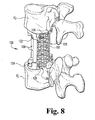
- the apparatus 20 is a modular vertebrectomy cage assembly positionable within an intervertebral space to span one or more vertebral levels along the longitudinal axis of the spinal column.
- the illustrated cage assembly 20 spans three vertebral levels ( FIG. 4 ), it should be understood that the cage assembly 20 may be configured to span a single vertebral level, two vertebral levels, or four or more vertebral levels.
- the cage assembly 20 is generally comprised of a first end member 22, a second end member 24, and one or more elongate support members or rods 26 coupled between the first and second end members 22, 24. Although the cage assembly 20 has been illustrated as including a pair of support rods 26, it should be understood that any number of support rods may be used, including a single support rod or three or more support rods.
- the support rods 26 have a solid configuration and a generally cylindrical shape. However, it should be understood that other shapes and configurations of the support rods 26 are also contemplated. For example, the support rods 26 may be configured as hollow tubes.
- the support rods 26 may take on other cross-sectional shapes, such as, for example, rectangular, hexagonal or elliptical cross-sectional shapes, or any other cross-sectional shape that would occur to one of skill in the art.
- the end members 22, 24 are adapted to engage the endplates of upper and lower vertebral bodies V U , V L ( FIG. 4 ).
- the support rods 26 are engaged between the end members 22, 24 to maintain an intervertebral axial space S between the upper and lower vertebral bodies V U , V L following the removal of one or more vertebral levels (shown in phantom).
- the support rods 26 are engaged to the end members 22, 24 via a number of fasteners, such as, for example, set screws 28.
- fasteners such as, for example, set screws 28.
- other means for engaging the support rods 26 to the end members 22, 24 are also contemplated as falling within the scope of the present invention.
- the end members 22, 24 are formed of a radiolucent material, such as, for example, a carbon fiber material. In this maimer, x-ray viewing of the intervertebral space S and the vertebral endplates subsequent to implantation of the cage assembly 20 will be relatively unobstructed.
- the end members 22, 24 may be formed of other suitable materials, such as, for example, stainless steel, titanium or other biocompatible materials.
- the support rods 26 are formed of stainless steel, titanium or other biocompatible materials.
- the support rods 26 and/or any other component of the cage assembly 20 may be formed of a radiolucent material, such as, for example, a carbon fiber material.
- end members 22, 24 With specific regard to the cage assembly 20, the end members 22, 24 are configured identical to one another. However, it should be understood that in other embodiments of the invention, the end members 22, 24 can take on different configurations, examples of which will be illustrated and described below.
- each of the end members 22, 24 has a parametrical configuration extending about an open inner region 30 and defining a lateral passage 32 communicating with open inner region 30.
- the end members 22, 24 are generally horseshoe-shaped.
- the end members 22, 24 could also be described as being U-shaped, C-shaped, V-shaped, semi-circular shaped, semi-oval shaped, or other terms that could be used to describe a shaped element defining an open inner region and a lateral passage communicating therewith.
- the end members 22, 24 may take on other types of hollow configurations, such as, for example, a circular shape, semi-oval shape, kidney shape, D-shape, or any other shape that would occur to one of skill in the art.
- the end members 22, 24 may take on substantially solid configurations, such as, for example, block-like or plate-like configurations that do not define an open inner region.
- the size and/or configuration of the end members 22, 24 may be specifically designed to accommodate any particular region of the spinal column and/or any particular vertebral level.
- the end members 22, 24 may be designed to have a D-shaped configuration
- embodiments of the invention associated with the lumbar region of the spine may be configured to have a horseshoe-shape, a U-shape, or other types of open-sided configurations.
- the end members 22, 24 have a lateral profile that is substantially complementary to the size and shape of the peripheral portion or outlying region of the vertebral bodies, such as the cortical rim or the apophyseal ring of the vertebral endplates.
- the outer perimeter of the end member 24 is preferably disposed generally above the inner edge of the cortical rim R of the lower vertebral body V L .
- the end members 22, 24 is engaged against the cortical region of the vertebral endplates, thereby minimizing the likelihood of subsidence into the relatively softer cancellous region of the upper and lower vertebral bodies V U , V L following implantation of the cage assembly 20 within the intervertebral space S .
- the parametrical configuration of the end members 22, 24 in combination with the relatively large surface area of the end members 22, 24 engaged against the vertebral endplates enhances the overall stability of the cage assembly 20.
- the open inner region 30 defined by each of the end member 22, 24 provides significant exposure of the vertebral endplates to enhance bony fusion between the upper and lower vertebral bodies V U , V L , the details of which will be discussed below.
- the end members 22, 24 include a main body or base portion 40 and a pair of oppositely disposed wings or side portions 42a, 42b extending from the base portion 40.
- the base portion 40 and the side portions 42a, 42b cooperate to define the open inner region 30, with the distal ends of the side portions 42a, 42b defining the lateral passage 32 therebetween.
- the lateral surface of the base portion 40 facing the open inner region 30 defines a recessed area 43 to eliminate the presence of sharp corners and which also serves to provide for a slightly larger open inner region 30 which correspondingly increases exposure of the vertebral endplates to enhance fusion capabilities.
- the upper/lower engaging surface 44 of the end members 22, 24 is substantially planar and defines surface features and/or a number of anchor elements adapted for engagement with the vertebral endplates to inhibit movement of the end members 22, 24 relative to the upper and lower vertebral bodies V U , V L .
- the upper/lower engaging surfaces 44 may be roughened, such as, for example, by knurling and/or etching (e.g., photochemical etching).
- various types of projections or protrusions may extend from the upper/lower engaging surfaces 44, such as, for example, a number of spikes, ridges, teeth, axial grooves, checkerboard-type grooves, or any other type of anchoring element that would occur to one of skill in the art.
- the upper/lower engaging surfaces 44 of the end members 22, 24 are illustrated as being arranged substantially parallel to one another when the cage assembly 20 is fully assembled ( FIG. 1 ), it should be understood that the upper/lower engaging surfaces 44 may be tapered relative to one another to more closely conform with the anatomical curvature of the spine at the surgical site (e.g., the angle of lordosis or kyphosis).
- the support rods 26 may be bent and/or provided with a predetermined curvature to more closely match the configuration of the cage assembly 20 with the anatomical curvature of the spine at the surgical site.
- the base portion 40 of the end members 22, 24 defines a pair of sockets or receptacles 46a, 46b sized to receive end portions of respective support rods 26 therein. It should be understood, however, that the base portion 40 may define any number of sockets or receptacles for receiving a corresponding number of support rods, including a single socket or three or more sockets.
- the sockets 46a, 46b each define a lateral opening 48 sized to receive the end portion of a corresponding support rod 26 therethrough. In this manner, the end portions of the support rods 26 may be laterally inserted into the sockets 46a, 46b via a side-loading technique, preferably from a posterior direction.
- Lateral insertion of the support rods 26 may be particularly advantageous when assembling the cage assembly 20 in situ within the intervertebral space S .
- the lateral openings 48 are preferably general aligned with the lateral passage 32 defined between the side portions 42a, 42b to further enhance the ability to laterally insert the support rods 26 into the sockets 46a, 46b.
- the sockets 46a, 46b each define a thru-opening 50 extending axially through the end members 22, 24 and sized to slidably receive the end portion of a corresponding support rod 26 therethrough. This embodiment of the invention may also be particularly advantageous when assembling the cage assembly 20 in situ within the intervertebral space S .
- sockets 46a, 46b may take on other alternative configurations.
- the end members 122, 124 associated with the cage assembly 100 define sockets that do not define lateral openings, but instead define a closed configuration.
- engagement of the support rods 126 with the end members 122, 124 would occur via axial insertion of the end portions of the support rods 126 into the sockets of the end members 122, 124.
- the end members 222, 224 associated with the cage assembly 200 also define a closed configuration.
- the sockets 46a, 46b have been illustrated as defining an axial thru-opening 50, in other embodiments of the invention, the sockets 46a, 46b may alternative define a closed or blind bottom configuration.
- the sockets 46a, 46b each define a laterally-extending threaded aperture 52 that is adapted to threadingly receive a corresponding set screw 28 therein ( FIG. 1 ).
- the set screws 28 are threaded into the apertures 52 and into engagement with the end portions of the support rods 26 to securely couple the end members 22, 24 thereto.
- the threaded apertures 52 are preferably generally aligned with the lateral passage 32 defined between the side portions 42a, 42b to provide substantially uninhibited access to the set screws 28 to facilitate tightening of the set screws 28 into the end members 22, 24.
- the threaded apertures 52 extend along axes 54a, 54b that are outwardly tapered relative to one another and to the sagittal plane P extending along the spinal column when the cage assembly 20 is positioned within the intervertebral space S ( FIG. 5 ). Arrangement of the set screw axes 54a, 54b in a diverging relationship tends to enhance the accessibility of the set screws 28.
- the set screw axes 54a, 54b are arranged to define an included angle ⁇ of about ten (10) to twenty (20) degrees. In a specific embodiment, the included angle ⁇ is about sixteen (16) degrees.
- the included angle ⁇ is about sixteen (16) degrees.
- other arrangements of the axes 54a, 54b are also contemplated as falling within the scope of the present invention, including parallel arrangements.
- the set screws 28 are of the break-off type, including a head portion that is selectively removable from a threaded shank portion, the details of which will be discussed below.
- set screws have been illustrated and described as the preferred means for coupling the support rods 26 to the end members 22, 24, other elements or devices may alternatively be used, such as, for example, various types of fasteners, snap rings, collets, collars, wedges, or any other type of element or device capable of coupling the support rods 26 to the end members 22, 24.
- either or both end portions of each support rod 26 may be threadingly engaged with a corresponding threaded portion defined by each of the end members 22, 24.
- the end members 22, 24 each define a tool receiving aperture 56.
- the tool receiving apertures 56 are sized and shaped to receive a corresponding end portion of a tool or instrument therein to facilitate insertion of the cage assembly 20 into the intervertebral space S, manipulation of the end members 22, 24 relative to the support rods 26, and/or distraction of the intervertebral space S.
- the tool receiving apertures 56 are illustrated as having a generally circular configuration, other shapes and configurations are also contemplated, such as, for example, hexagonal or rectangular configurations.
- the tool receiving apertures 56 are formed in the base portion 40 of the end members 22, 24 through an inwardly facing surface 58 (the surface opposite the outer engaging surface 44).
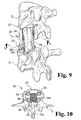
- the tool receiving apertures 56 may be formed in other portions of the end members 22, 24, including the side portions 42a, 42b (see FIGS. 9 and 10 ), and through other surfaces, such as the laterally extending surfaces of the end members 22, 24.
- the sockets 46a, 46b associated with the end members 22, 24 have been depicted as having an axially extending cylindrical configuration adapted to receive a correspondingly shaped end portion of a support rod 26 therein, In this manner, when the support rods 26 are properly positioned within the sockets 46a, 46b, the support rods 26 will be arranged at a predetermined angular orientation relative to the end members 22, 24, which in turn arranges the end members 22, 24 at predetermined angular orientations relative to one another.
- sockets 46a, 46b and/or the end portions of the support rods 26 may be configured such that the angular orientation of the support rods 26 relative to the end members 22, 24 may be varied or adjusted to correspondingly arrange the end members 22, 24 at select angular orientations relative to one another.
- the cage assembly 400 is generally comprised of a first end member 422, a second end member 424, and one or more elongate support members or rods 426 coupled between the first and second end members 422, 424.
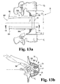
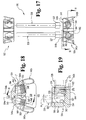
- the cage assembly 400 is configured to allow the support rods 426 to pivot relative to at least one of the end members 422, 424, and includes a number of fasteners, such as, for example, set screws 428 ( FIG. 16 ) adapted to lock the support rods 426 at a select angular orientation relative to the end members 422, 424.
- the cage assembly 400 has been illustrated as including a pair of support rods 426, it should be understood that any number of support rods may be used, including a single support rod or three or more support rods.
- the support rods 426 are configured similar to the support rods 26 illustrated and described above with regard to the cage assembly 20, having a solid configuration and a substantially cylindrical shape. However, unlike the support rods 26, one end portion of the support rods 426 defines a spherical-shaped end portion 427, the purpose of which will be discussed below, with the opposite end portion defining an axially extending cylindrical configuration. In this manner, the end portion defining the axially extending cylindrical configuration may be cut to an appropriate length that provides the cage assembly 400 with an overall height which closely matches the natural or corrected height of the intervertebral space S. It should be understood, however, that in other embodiments of the invention, each end portion of the support rods 426 may define a spherical-shaped end portion 427.
- the end member 422 is configured substantially identical to the end members 22, 24 illustrated and described above with regard to the cage assembly 20, including sockets configured similar to sockets 46a, 46b for receiving the axially extending cylindrical end portions of the support rods 426 therein.
- the end member 424 is configured similar to the end member 422.
- the end member 424 has a parametrical configuration extending about an open inner region 430 and defining a lateral passage 432 communicating with the open inner region 430.
- the end member 424 has a base portion 440, a pair of oppositely disposed wings or side portions 442a, 442b, an upper/lower engaging surface 444, a pair of sockets or receptacles 446a, 446b defining lateral openings 448, threaded aperture 452 extending along axes 454a, 454b, and a tool receiving aperture 456.
- the end member 424 is configured to pivotally receive the spherical-shaped end portions 427 of the support rods 426 to allow for relative pivotal movement between the support rods 426 and the end member 424, the details of which will follow.
- the sockets 446a, 446b each include an axially extending cylindrical-shaped portion 460 and a spherical-shaped recessed portion 462 sized and shaped to receive the spherical-shaped end portion 427 of a respective support rod 426 therein.
- the support rods 426 are allowed to pivot relative to the end member 424 about multiple axes, and in any direction relative to the end member 424, within a range of angular orientations.
- This multi-axial configuration allows the support rods 426 to be arranged at various angular orientations relative to the end member 424, which in turn allows the end member 424 to be arranged at various angular orientations relative to the end member 422.
- each of the support rods 426 need not necessarily have the same overall length. Instead, the support rods 426 may define different lengths to allow for more precise adjustment of the angular orientation between the end members 422, 424, particularly in cases where the support rods 426 are not arranged along a common plane, such as, for example, the support rods 126 associated with the cage assembly 100 ( FIGS. 7 and 8 ). Additionally, the support rods 426 may be curved or bent to provide further adjustment to the angular orientation between the end members 422, 424.
- the support rod 426 is allowed to pivot up to an angle ⁇ 1 in any direction, limited only by engagement of the support rod 426 against a surface 466 defined by the cylindrical portion 460 of the sockets 446a, 446b.
- the surface 466 is tapered at an angle approximately equal to the angle ⁇ 1 .
- at least a portion of the spherical-shaped recessed portion 462 of the sockets 446a, 446b defines a number of surface projections or protrusions 464, such as, for example, a series of ridges or teeth and/or spikes, the purpose of which will be discussed below.
- the surface projections or protrusions 464 are positioned generally opposite the threaded aperture 452; however, it should be understood that other positions configurations are also contemplated.
- the threaded aperture 452 communicating with the sockets 446a, 446b has a diameter approximately equal to or slightly greater than the diameter of the spherical-shaped recessed portion 462.
- the spherical-shaped end portions 427 of the support rod 426 may be laterally inserted into the sockets 446a, 446b via a side-loading technique, which may be particularly advantageous when assembling the cage assembly 400 in situ within the intervertebral space S .
- the cylindrical portion 460 of the sockets 446a, 446b has a diameter somewhat less than the spherical-shaped end portion 427 of the support rod 426 to aid in retaining the support rods 426 in axial engagement with the end member 424.
- a set screw 428 is threadingly advanced through the threaded aperture 452 and into engagement with the spherical-shaped end portion 427 to lock the support rod 426 in a select angular orientation relative to the end member 424.
- the set screws 428 is of the break-off type, including a threaded shank portion 470 adapted for engagement within the threaded aperture 452, and a head portion 472 extending from the threaded shank portion 470 and adapted for engagement by the distal end portion of a driving tool (not shown).
- the head portion 472 is selectively removable from the threaded portion 470.
- the head portion 472 is attached to the threaded portion 470 via a frangible region or fracture initiator 474 adapted to allow the head portion 472 to be snapped off or broken away from the threaded portion 470 once properly engaged against the spherical end portion 427 of the support rod 426.
- the distal end of the threaded portion 470 defines a number of projections or protrusions 476, such as, for example, a ring-like ridge and/or a series of teeth or spikes that are configured to enhance engagement of the set screw 428 with the spherical end portion 427 of the support rod 426 to provide additionally resistance to relative pivotal movement between the end member 424 and the support rod 426.
- a number of projections or protrusions 476 such as, for example, a ring-like ridge and/or a series of teeth or spikes that are configured to enhance engagement of the set screw 428 with the spherical end portion 427 of the support rod 426 to provide additionally resistance to relative pivotal movement between the end member 424 and the support rod 426.
- the cage assembly 500 is generally comprised of a first end member 522, a second end member 524, and one or more elongate support members or rods 526 coupled between the first and second end members 522, 524.
- the cage assembly 500 is configured to allow the support rods 526 to pivot relative to at least one of the end members 522, 524, and includes a number of fasteners, such as, for example, set screws 528 ( FIG. 19 ) adapted to lock the support rods 526 at a select angular orientation relative to the end members 522, 524.
- the cage assembly 500 has been illustrated as including a pair of support rods 526, it should be understood that any number of support rods may be used, including a single support rod or three or more support rods.
- the support rods 526 are configured similar to the support rods 426 illustrated and described above with regard to the cage assembly 400. However, instead of defining a spherical-shaped end portion, the support rods 526 define a cylindrical-shaped end portion 527 extending in a direction transverse to the longitudinal axis of the support rod 526 to define a T-bar arrangement, the function of which will be discussed below. Similar to the support rods 426, the end portion of the support rods 526 opposite the transversely extending cylindrical-shaped end portion 527 defines an axially extending cylindrical configuration. It should be understood, however, that in other embodiments of the invention, each end portion of the support rods 526 may define a transversely extending cylindrical-shaped end portion 527.
- the end member 522 is configured substantially identical to the end member 422 illustrated and described above with regard to the cage assembly 400, including sockets configured to receive the axially extending cylindrical end portions of the support rods 526 therein.
- the end member 524 is configured similar to the end member 522.
- the end member 524 has a parametrical configuration extending about an open inner region 530 and defining a lateral passage 532 communicating with the open inner region 530.
- the end member 524 has a base portion 540, a pair of oppositely disposed wings or side portions 542a, 542b, an upper/lower engaging surface 544, a pair of sockets or receptacles 546a, 546b defining lateral openings 548, threaded aperture 552 extending along axes 554a, 554b, and a tool receiving aperture 556.
- the end member 524 is configured to pivotally receive the cylindrical-shaped end portions 527 of the support rods 526 to allow for relative pivotal movement between the support rods 526 and the end member 524, the details of which will follow.
- the sockets 546a, 546b each include an axially extending cylindrical-shaped portion 560 and a transversely extending cylindrical-shaped recessed portion 562 sized and shaped to receive the cylindrical-shaped end portion 527 of a respective support rod 526 therein.
- the support rods 526 are allowed to pivot relative to the end member 524 in a hinge-like manner about a transverse axis T within a range of angular orientations.
- the end portion 527 of the support rods 526 and the corresponding socket 546a, 546b of the end member 524 are configured to allow selective angular displacement of the support rods 526 relative to the end member 524 about a single axis.
- This mono-axial configuration substantially prevents angular displacement of the support rods 526 relative to the end member 524 about any axis other than the transverse axis T.
- alternative configurations are also contemplated, including bi-axial configurations wherein the end portions 527 of the support rods 526 and the corresponding sockets 546a, 546b are configured to allow selective angular displacement of the support rods 526 relative to the end member 524 about two axes (e.g., the transverse axis T and an axis arranged substantially perpendicular to and co-planar with the transverse axis T).
- the cage assembly 400 other multi-axial configurations are also contemplated as falling within the scope of the present invention.
- the support rod 526 is allowed to pivot up to an angle ⁇ 2 along a single plane (e.g., in a posterior-anterior direction), limited only by engagement of the support rod 526 against a surface 566 defined by the axially-extending cylindrical portion 560 of the sockets 546a, 546b.
- the surface 566 is tapered at an angle approximately equal to the angle ⁇ 2 .
- At least a portion of the cylindrical-shaped recessed portion 562 of the sockets 546a, 546b defines a number of surface projections or protrusions 564, such as, for example, a series of ridges or teeth and/or spikes, the purpose of which will be discussed below.
- the surface projections or protrusions 564 are positioned generally opposite the threaded aperture 552; however, it should be understood that other configurations are also contemplated.
- the threaded aperture 552 is configured to receive the cylindrical-shaped end portion 527 of the support rod 526 therethrough such that the end portion 527 may be laterally inserted into the sockets 546a, 546b via a side-loading technique.
- the cylindrical portion 560 of the sockets 546a, 546b has a diameter somewhat less than the outer cross-section of the end portion 527 to aid in retaining the support rods 526 in axial engagement with the end member 524.
- a set screw 528 is threadingly advanced through the threaded aperture 552 and into engagement with the end portion 527 to lock the support rod 526 in a select angular orientation relative to the end member 524.
- the set screw 528 may be configured similar to the break-off type set screw 428 illustrated and described above, or may alternatively take on other configurations.
- the distal end of the set screw 528 preferably defines a number of projections or protrusions 576, such as, for example, a ring-like ridge and/or a series of teeth or spikes that are configured to enhance engagement of the set screw 528 with the cylindrical-shaped end portion 527 of the support rod 526 to provide additionally resistance to relative pivotal movement between the end member 524 and the support rod 526.
- a number of projections or protrusions 576 such as, for example, a ring-like ridge and/or a series of teeth or spikes that are configured to enhance engagement of the set screw 528 with the cylindrical-shaped end portion 527 of the support rod 526 to provide additionally resistance to relative pivotal movement between the end member 524 and the support rod 526.
- a cage assembly 20 positioned between the upper and lower vertebral bodies V U , V L to maintain the intervertebral space S following removal of a number of vertebral levels (shown in phantom).
- the end members 22, 24 and the support members 26 are configured to allow the cage assembly 20 to be assembled in situ within the intervertebral space S. It is also contemplated that the components of the cage assembly 20 may be endoscopically inserted into and assembled within the intervertebral space S in a minimally invasive manner.
- the components of the cage assembly 20 may be assembled into one or more sub-assemblies outside of the intervertebral space S, with final assembly of the cage assembly 20 taking place in situ within the intervertebral space S .
- the cage assembly 20 may be entirely pre-assembled outside of the patient's body prior to insertion within the intervertebral space S.
- the entire cage assembly 20 or the individual components of the cage assembly 20 are inserted into the intervertebral space S via a posterior surgical approach.
- the cage assembly 20 or the individual components of the cage assembly 20 may be inserted into the intervertebral space S via other surgical approaches, such as, for example, an anterior approach or a lateral approach.
- the open inner regions 30 of the end members 22, 24 are preferably positioned generally along the sagittal plane P, with the lateral passages 32 and the open inner region 30 generally facing a posterior direction.
- the engaging surfaces 44 of the end members 22, 24 are positioned against the endplates of the upper and lower vertebral bodies V U , V L , with the support members 26 extending between the end members 22, 24 to maintain a desired height of the intervertebral space S .
- the outer peripheral portion of the end member 24 (as well as the end member 22) is preferably positioned generally above the inner edge of the cortical rim R of the vertebral body.
- the end members 22, 24 is engaged against the relatively hard cortical portion of the vertebral endplates, thereby minimizing the likelihood of subsidence of the cage assembly 20 into the relatively soft cancellous portion of the upper and lower vertebral bodies V U , V L .
- the open inner region 30 defined by each of the end member 22, 24 provides significant exposure of the vertebral endplates to enhance bony fusion between the upper and lower vertebral bodies V U , V L .
- the support rods 26 may be inserted through the lateral passages 48 of the end members 22, 24 and into the sockets 46a, 46b via a side-loading technique. This technique may be particularly advantageous when assembling the cage assembly 20 in situ within the intervertebral space S .
- the support rods 26 may be pre-assembled with the end members 22, 24 prior to insertion into the intervertebral space S .
- the set screws 28 are tightened into engagement against the end portions of the support rods 26.
- the set screws 28 function to secure the support rods 26 to the end members 22, 24, thereby fixing the overall height h of the cage assembly 20 to maintain the desired height of the intervertebral space S .
- the cage assembly 20 may include a number of elongate rods or posts 29 (shown in phantom).
- the elongate posts 29 are coupled to the end members 22, 24 and extend outside of the intervertebral space S .
- the elongate posts 29 extend from the set screws 28, and in a further embodiment are formed integral with the set screws 28 to define a unitary, single-piece structure.
- the elongate posts 29 provide a means for coupling various components to the cage assembly 20 at a location outside of the intervertebral space S.
- various types and configurations of spinal stabilization systems such as, for example, plate or rod type systems, may be operably attached to the elongate posts 29 to provide additional stability and structural integrity to the cage assembly 20 and/or to provide additional stabilization and support to the portion of the spinal column being treated.
- the entire cage assembly 20 or the individual components of the cage assembly 20 may be inserted into the intervertebral space S via a posterior surgical approach.
- a posterior surgical approach Referring to FIGS. 6A-6C , illustrated therein is a posterior insertion technique
- the parametrical configuration of the end members 22, 24 facilitates advancement of the end members 22, 24 and/or the entire cage assembly 20 around the spinal cord C and into the intervertebral space S in such a manner as to minimize retraction and/or manipulation of the spinal cord C and other neural structures.
- the spinal cord C may be slightly retracted in a lateral direction in the direction of arrow 80 via a retractor instrument 82.
- the spinal cord C need not necessarily be retracted to accommodate insertion of the cage assembly 20 into the intervertebral space S .
- the cage assembly 20, with the open inner regions 30 and lateral passages 32 of the end members 22, 24 initially facing the spinal cord C is rotated or wrapped about the spinal cord C in the direction of arrow 84 while simultaneously being slightly displaced in the direction of arrow 86. In this manner, the distal end portions of the end members 22, 24 are displaced about the spinal cord C along an arc-shaped displacement path. As illustrated in FIGS.
- various types and configurations of fusion devices and/or bone growth promoting materials may be introduced within the intervertebral space adjacent the cage assembly to facilitate or promote bony fusion between the upper and lower vertebral bodies V U , V L .
- fibular strut 190 disposed between the upper and lower vertebral bodies V U , V L adjacent the cage assembly 100.
- the fibular strut 190 has opposite end portions that are positioned within the open inner regions 130 of each of the end members 122, 124, and are preferably positioned in intimate engagement with the vertebral endplates of the upper and lower vertebral bodies V U , V L .
- a fusion cage 192 disposed between the upper and lower vertebral bodies V U , V L adjacent the cage assembly 100.
- the fusion cage 192 has a cylindrical-shaped configuration and is formed of mesh material. However, it should be understood that other types, shapes and configurations of fusion cages are also contemplated for use in association with the present invention. Similar to the fibular strut 190, the mesh fusion cage 192 has opposite end portions that are positioned within the open inner regions 130 of each of the end members 122, 124, and are preferably positioned in intimate engagement with the vertebral endplates. The mesh fusion cage 192 may be filled with various types of bone growth materials to promote bony fusion between the upper and lower vertebral bodies V U , V L , the details of which would be apparent to one of skill in the art. It should be understood that other types of cages or devices for containing bone growth materials are also contemplated as falling within the scope of the present invention.
- a bone growth material 290 disposed between the upper and lower vertebral bodies V U , V L adjacent the cage assembly 200.
- the material 290 is contained within the intervertebral space S via a resorbable film or membrane 292.
- the resorbable film 292 is comprised of an inner film portion 292a extending about the inner perimeter of the cage assembly 200, and an outer film portion 292b positioned across the open posterior side of the cage assembly 200 to fully contain the bone growth material 290 therein. It should be understood that the inner portion 292a of the resorbable film 292 may extend entirely about the bone growth material 290 to fully encase the material 290.
- the resorbable film 292 may extend about the outer perimeter of the cage assembly 200 to contain the bone growth material 290 within the intervertebral space S.
- Other types of devices and materials for containing the bone growth material 290 are also contemplated for use in association with the present invention, including the use of non-resorbable materials.
- bone growth materials may include, for example, bone graft, bone morphogenetic protein (BMP), allograft, various types of cement, transforming growth factor 131, insulin-like growth factor 1, platelet-derived growth factor, fibroblast growth factor, and LIM mineralization protein.
- BMP bone morphogenetic protein
- the bone growth promoting materials may be provided in a carrier, such as, for example, a sponge, a block, folded sheets, putty and/or paste.
- the cage assembly 100 includes a first end member 122, a second end member 124, and three elongate support rods 126 coupled between the first and second end members 122, 124 and engaged thereto via a number of fasteners or set screws 128.
- the support rods 126 are preferably spaced about the end members 122, 124 and the open inner region 130 in a generally uniform manner.
- the cage assembly 200 includes a first end member 222, a second end member 224, and two elongate support rods 226 coupled between the first and second end members 222, 224 and engaged thereto via a number of fasteners or set screws 228.
- the anterior portions of the end members 222, 224 are somewhat less prominent than the anterior portions of the end members 22, 24, thereby providing for a slightly larger open inner region 230 which in turn provides for a slightly greater exposure of the vertebral endplates.
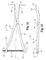
- the distractor 300 extends along a longitudinal axis L and is generally comprised of a first distractor arm 302 and a second distractor arm 304.
- the first and second distractor arms 302, 304 are coupled to one another via a hinge mechanism or pivot pin 306 which provides for pivotal movement between the distractor arms 302, 304 about a pivot axis 308.
- a hinge mechanism or pivot pin 306 which provides for pivotal movement between the distractor arms 302, 304 about a pivot axis 308.
- an inward compression force exerted onto the proximal portions 302a, 304a of the distractor arms in the direction of arrows A will cause the distal end portions 302b, 304b to be outwardly displaced in the direction of arrows B.
- the distractor 300 is provided with a gauge or stop member 310 that is adapted to limit outward displacement of the distal end portion 302b, 304b, which in turn correspondingly limits that amount of distraction provided by the distractor arms 302, 304.
- the gauge member 310 is configured as a threaded rod having a first end portion 310a engagable with the proximal end portion 304a of the distractor arm 304, and a second end portion 310b engaged within an opening or slot 312 extending through the proximal end portion 302a of the distractor arm 302.
- the position of rod 310 may be adjusted relative to the distractor arm 302 (e.g., by threading the rod 310 into or out of the opening 312) to corresponding control the maximum amount of distraction provided by the distractor arms 302, 304. In this manner, over distraction of the intervertebral space S is avoided.
- the distal end portions 302b, 304b of the distractor arms 302, 304 preferably define a lateral offset relative to the longitudinal axis L, the purpose of which will be discussed below.
- the distal end portions 302b, 304b have an arcuate-shaped configuration defining the lateral offset.
- the distal end portions 302b, 304b each preferably define an outwardly extending projection 320 sized and shaped to be received within the tool receiving aperture 56 formed in each of the end member 22, 24.
- the projections 320 have a hemi-spherical configuration; however, other shapes and configurations are also contemplated.
- the distractor arms 302, 304 are engagable with the end members 22, 24, respectively, via insertion of the projections 320 within the tool receiving apertures 56.
- the components of the cage assembly 20 are preferably inserted into the intervertebral space S via a posterior surgical approach.
- the distractor 300 is likewise preferably inserted into the intervertebral space S via a posterior surgical approach.
- the longitudinal axis L of the distractor 300 is generally aligned with the patient's spinal cord C when the distractor arms 302, 304 are properly engaged with the end members 22, 24.
- the lateral offset defined by the distal end portions 302b, 304b of the distractor arms 302, 304 provide the distractor 300 with the ability to wrap or extend around the spinal cord C to minimize manipulation and retraction of the spinal cord C while still maintaining secure and stable engagement with the end members 22, 24. In this manner, the risk of injury or trauma to the spinal cord C and other neural structures is reduced.
- the distal end portions 302b, 304b are outwardly displaced or spread apart, which in turn urges the end members 22, 24 against the opposing vertebral endplates to distract the upper and lower vertebral bodies V U , V L to a desired distraction height.
- the set screws 28 are tightened into engagement with the support rods 26 to fix the overall height h of the cage assembly 20 and to maintain the desired distraction height of the intervertebral space S .
- a fusion device and/or a bone growth material may then be inserted into the intervertebral space S adjacent the cage assembly 20.
- various types of fusion devices or materials may be used to facilitate or promote bony fusion between the upper and lower vertebral bodies V U , V L inlcuding, for example, the fibular strut 190, the fusion cage 192, or the bone growth material 290 contained within the intervertebral space S via the resorbable film 292.
- the support rods 26 are preloaded into the sockets 46a, 46b of the end members 22, 24 prior to distraction of the intervertebral space S , with the end portions of the support rods 26 extending through the axial thru-openings 50 associated with at least one of the end members 22, 24. In this manner, during distraction, at least one of the end members 22, 24 is slidably displaced along the support rods 26 until the desired distraction height is attained, followed by tightening of the set screws 28 to fix the overall height h of the cage assembly 20.
- the end members 22, 24 may be inserted into the intervertebral space S and spread apart until the desired distraction height is attained, followed by insertion of the support rods 26 into the sockets 46a, 46b and tightening of the set screws 28 to fix the overall height h of the cage assembly 20.
- the cage assemblies 400 and 500 of the present invention enable complete vertebral reconstruction following a vertebrectomy, preferably via a posterior surgical approach.
- the components of the cage assemblies extend or wrap about the spinal cord C and emerging nerve roots to minimize the risk of injury to these neural structures.
- the upper and lower end members of the cage assemblies are engaged against the cortical rim or apophyseal ring of the vertebral endplates, thereby reducing the likelihood of subsidence into the upper and lower vertebrae.
- the cage assemblies of the present invention also provide substantial exposure of the vertebral endplates to promote fusion between the upper arid lower vertebral bodies.
- the cage assemblies provide for relatively uninhibited post-operative follow up with regard to verification of proper fusion/bone growth between the upper and lower vertebral bodies.
Landscapes
- Health & Medical Sciences (AREA)
- Engineering & Computer Science (AREA)
- Biomedical Technology (AREA)
- Life Sciences & Earth Sciences (AREA)
- General Health & Medical Sciences (AREA)
- Public Health (AREA)
- Heart & Thoracic Surgery (AREA)
- Orthopedic Medicine & Surgery (AREA)
- Surgery (AREA)
- Animal Behavior & Ethology (AREA)
- Veterinary Medicine (AREA)
- Neurology (AREA)
- Nuclear Medicine, Radiotherapy & Molecular Imaging (AREA)
- Molecular Biology (AREA)
- Medical Informatics (AREA)
- Cardiology (AREA)
- Oral & Maxillofacial Surgery (AREA)
- Transplantation (AREA)
- Vascular Medicine (AREA)
- Prostheses (AREA)
- Load-Engaging Elements For Cranes (AREA)
- Vehicle Body Suspensions (AREA)
- Forklifts And Lifting Vehicles (AREA)
Claims (24)
- Vorrichtung zum Abstützen von Wirbelkörpern, aufweisend:ein erstes End-Element (422), das angepasst ist, um mit einer unteren Endplatte eines ersten Wirbelkörpers in Eingriff zu sein,ein zweites End-Element (424), das angepasst ist, um mit einer oberen Endplatte eines zweiten Wirbelkörpers in Eingriff zu sein,mindestens ein längliches Abstützelement (426), das zwischen dem ersten und dem zweiten End-Element zur Aufrechterhaltung eines axialen Raums zwischen dem ersten und dem zweiten Wirbelkörper eingekuppelt ist, undwobei jedes von dem ersten und dem zweiten End-Element eine Umfangs-Konfiguration aufweist, die sich um einen offenen Innenbereich (430) erstreckt und einen seitlichen Durchgang (432) definiert, der mit dem oberen Innenbereich in Kommunikation ist, dadurch gekennzeichnet, dass mindestens eines von dem ersten und dem zweiten End-Element mindestens eine Buchse (446a, 446b) aufweist, die so bemessen ist, dass sie einen jeweiligen Endabschnitt von dem mindestens einen länglichen Abstützelement darin aufnimmt, undwobei die mindestens eine Buchse und der jeweilige Endabschnitt des länglichen Abstützelements zum Zulassen einer Drehbewegung des länglichen Abstützelements relativ zu dem mindestens einen von dem ersten und dem zweiten End-Element um mindestens eine Achse angepasst sind.
- Vorrichtung gemäß Anspruch 1, wobei jedes von dem ersten und dem zweiten End-Element hufeisenförmig ist.
- Vorrichtung gemäß Anspruch 1, wobei jedes von dem ersten und dem zweiten End-Element U-förmig ist.
- Vorrichtung gemäß Anspruch 1, wobei der offene Innenbereich des ersten und des zweiten End-Elements im Wesentlichen entlang der Sagittalebene positionierbar ist.
- Vorrichtung gemäß Anspruch 1, wobei jedes von dem ersten und dem zweiten End-Element mindestens eine sich seitlich erstreckende Öffnung (452) in Kommunikation mit der mindestens einen Buchse aufweist, und
ferner Befestigungen (428) aufweisend, die in jeweiligen der sich seitlich erstreckenden Öffnungen positioniert sind und mit dem jeweiligen Endabschnitt von dem mindestens einen länglichen Abstützelement in Eingriff sind, zum Verbinden des ersten und des zweiten End-Element mit dem mindestens einen länglichen Abstützelement. - Vorrichtung gemäß Anspruch 5, wobei jede von der mindestens einen der sich längs erstreckenden Öffnungen im Wesentlichen mit dem seitlichen Durchgang fluchtet.
- Vorrichtung gemäß Anspruch 5, wobei die Befestigungen Stellschrauben sind.
- Vorrichtung gemäß Anspruch 1, wobei die mindestens eine Buchse eine seitliche Öffnung aufweist, die so bemessen ist, dass sie den entsprechenden Endabschnitt des mindestens einen länglichen Abstützelements dadurch hindurch aufnimmt.
- Vorrichtung gemäß Anspruch 8, wobei die seitliche Öffnung im Wesentlichen mit dem seitlichen Durchgang fluchtet.
- Vorrichtung gemäß Anspruch 1, wobei sich die mindestens eine Buchse axial durch jeweilige des ersten und des zweiten End-Elements erstreckt, zum Hindurchpassieren des jeweiligen Endabschnitts des mindestens einen länglichen Abstützelements.
- Vorrichtung gemäß Anspruch 1, wobei die mindestens eine Buchse eine sphärisch geformte Aussparung (462) aufweist, wobei der jeweilige Endabschnitt des mindestens einen länglichen Abstützelements einen sphärisch geformten Endabschnitt aufweist, der in der sphärisch geformten Aussparung angeordnet ist, zum Zulassen der Drehbewegung um mehrere Achsen.
- Vorrichtung gemäß Anspruch 1, wobei die mindestens eine Buchse eine zylinderförmige Aussparung (460) aufweist, wobei der jeweilige Endabschnitt des mindestens einen länglichen Abstützelements einen zylinderförmigen Endabschnitt aufweist, der in der zylinderförmigen Aussparung angeordnet ist, um die Drehbewegung um die mindestens eine Achse zu ermöglichen.
- Vorrichtung gemäß Anspruch 1, wobei das mindestens eine von dem ersten und dem zweiten End-Element mindestens eine sich seitlich erstreckende Öffnung in Kommunikation mit der mindestens einen Buchse aufweist, und
ferner eine Befestigung aufweisend, die in der sich seitlich erstreckenden Öffnung positioniert ist und mit dem jeweiligen Endabschnitt des mindestens einen länglichen Abstützelement in Eingriff ist, zum Festlegen des länglichen Abstützelements in einer ausgewählten Winkelausrichtung relativ zu dem mindestens einen von dem ersten und dem zweiten End-Element. - Vorrichtung gemäß Anspruch 13, wobei die mindestens eine Buchse eine Anzahl von Oberflächen-Vorsprüngen (464) definiert, die zum Eingreifen in den jeweiligen Endabschnitt des mindestens einen länglichen Abstützelements angepasst sind, zum Unterstützen des Festlegens des länglichen Abstützelements in der ausgewählten Winkelausrichtung relativ zu dem mindestens einen von dem ersten und dem zweiten End-Element.
- Vorrichtung gemäß Anspruch 1, ferner eine Mehrzahl der länglichen Abstützelemente aufweisend, die zwischen dem ersten und dem zweiten End-Element eingekuppelt sind.
- Vorrichtung gemäß Anspruch 15, wobei die Mehrzahl der länglichen Abstützelemente mindestens drei längliche Abstützelemente aufweist, die in einem gleichmäßigen Abstand um den offenen Innenbereich des ersten und des zweiten End-Elements angeordnet sind.
- Vorrichtung gemäß Anspruch 1, wobei mindestens eines von dem ersten und dem zweiten End-Element aus einem strahlendurchlässigen Material gebildet ist.
- Vorrichtung gemäß Anspruch 1, wobei das mindestens eine längliche Abstützelement aus einem strahlendurchlässigen Material gebildet ist.
- Vorrichtung gemäß Anspruch 1, ferner ein Fusionselement aufweisend, das angepasst ist zum Einsetzen in den axialen Raum benachbart zu jedem von den offenen Innenbereichen des ersten und des zweiten End-Elements, zum Unterstützen der Fusion zwischen dem ersten und dem zweiten Wirbelkörper.
- Vorrichtung gemäß Anspruch 1, wobei das erste und das zweite End-Element und das mindestens eine längliche Abstützelement zum Zulassen des Zusammenbauens der Vorrichtung in situ innerhalb des axialen Raums zwischen dem ersten und dem zweiten Wirbelkörper eingerichtet sind.
- Vorrichtung gemäß Anspruch 1 in Kombination mit einem Distraktor-Instrument (300), das einen ersten und einen zweiten Distraktor-Arm (302, 304) aufweist, die sich insgesamt entlang einer Längsachse erstrecken, wobei der erste Distraktor-Arm einen ersten distalen Endabschnitt (302b) aufweist, der mit dem ersten End-Element in Eingriff gebracht werden kann, wobei der zweite Distraktor-Arm einen zweiten distalen Endabschnitt (304b) aufweist, der mit dem zweiten End-Element in Eingriff gebracht werden kann, wobei der erste und der zweite distale Endabschnitt eine seitliche Versetzung relativ zu der Längsachse definieren.
- Vorrichtung gemäß Anspruch 21, wobei der erste und der zweite distale End-Abschnitt des Distraktors eine bogenförmige Konfiguration aufweisen, die die seitliche Versetzung definiert.
- Vorrichtung gemäß Anspruch 22, wobei die Längsachse insgesamt nach der Wirbelsäule des Patienten ausgerichtet ist, wenn der Distraktor mit dem ersten und dem zweiten End-Element mit dem bogenförmigen ersten und zweiten distalen Endabschnitt, die sich um die Wirbelsäule erstrecken, in Eingriff ist.
- Vorrichtung gemäß Anspruch 21, wobei der erste und der zweite distale End-Abschnitt des Distraktor-Instruments jeweils einen Vorsprung (320) definieren, der eine derartige Größe und Form aufweist, dass er in einer entsprechenden Aussparung aufgenommen wird, die in jedem von dem ersten und dem zweiten End-Element ausgebildet ist.
Applications Claiming Priority (2)
| Application Number | Priority Date | Filing Date | Title |
|---|---|---|---|
| US10/407,010 US7563281B2 (en) | 2003-04-03 | 2003-04-03 | Apparatus and method for supporting vertebral bodies |
| PCT/US2004/009748 WO2004089260A1 (en) | 2003-04-03 | 2004-03-31 | Apparatus and method for supporting vertebral bodies |
Publications (2)
| Publication Number | Publication Date |
|---|---|
| EP1615599A1 EP1615599A1 (de) | 2006-01-18 |
| EP1615599B1 true EP1615599B1 (de) | 2008-12-10 |
Family
ID=33097451
Family Applications (1)
| Application Number | Title | Priority Date | Filing Date |
|---|---|---|---|
| EP04749539A Expired - Lifetime EP1615599B1 (de) | 2003-04-03 | 2004-03-31 | Gerät zur unterstützung von wirbelkörpern |
Country Status (7)
| Country | Link |
|---|---|
| US (3) | US7563281B2 (de) |
| EP (1) | EP1615599B1 (de) |
| AT (1) | ATE416731T1 (de) |
| AU (1) | AU2004227832B9 (de) |
| CA (1) | CA2523609A1 (de) |
| DE (1) | DE602004018295D1 (de) |
| WO (1) | WO2004089260A1 (de) |
Families Citing this family (56)
| Publication number | Priority date | Publication date | Assignee | Title |
|---|---|---|---|---|
| US7491205B1 (en) | 1988-06-13 | 2009-02-17 | Warsaw Orthopedic, Inc. | Instrumentation for the surgical correction of human thoracic and lumbar spinal disease from the lateral aspect of the spine |
| US7819922B2 (en) * | 2003-10-16 | 2010-10-26 | Spinal Generations, Llc | Vertebral prosthesis |
| USD620594S1 (en) * | 2004-06-25 | 2010-07-27 | American Prosthetic Components, Inc. | Offset alignment device |
| DE102005022921B3 (de) * | 2005-05-19 | 2007-01-25 | Aesculap Ag & Co. Kg | Wirbelkörperersatzimplantat |
| US7520888B2 (en) * | 2006-02-14 | 2009-04-21 | Warsaw Orthopedic, Inc. | Treatment of the vertebral column |
| US7862618B2 (en) * | 2006-07-19 | 2011-01-04 | Warsaw Orthopedic, Inc. | Expandable vertebral body implants and methods of use |
| US20080114457A1 (en) * | 2006-11-14 | 2008-05-15 | Warsaw Orthopedic, Inc. | Methods and devices for connecting implants and devices |
| WO2008065450A1 (en) | 2006-11-29 | 2008-06-05 | Surgicraft Limited | Orthopaedic implants and prostheses |
| US7875079B2 (en) | 2006-12-14 | 2011-01-25 | Warsaw Orthopedic, Inc. | Vertebral implant containment device and methods of use |
| WO2008098054A2 (en) | 2007-02-06 | 2008-08-14 | Pioneer Surgical Technology, Inc. | Intervertebral implant devices and methods for insertion thereof |
| US20090110637A1 (en) * | 2007-10-26 | 2009-04-30 | Warsaw Orthopedic, Inc. | LMP and Regulation of Tissue Growth |
| US8267939B2 (en) | 2008-02-28 | 2012-09-18 | Stryker Spine | Tool for implanting expandable intervertebral implant |
| US8062368B2 (en) | 2008-04-24 | 2011-11-22 | Warsaw Orthopedic, Inc. | Expandable vertebral implants and methods of use |
| FR2945436A1 (fr) * | 2009-05-14 | 2010-11-19 | Tornier Sa | Instrumentation chirurgicale de distraction osseuse de l'epaule |
| ES2542006T3 (es) * | 2008-09-05 | 2015-07-29 | Biedermann Technologies Gmbh & Co. Kg | Dispositivo de estabilización ósea, en particular para la columna vertebral |
| WO2010062945A1 (en) * | 2008-11-26 | 2010-06-03 | Synthes Usa, Llc | Brachytherapy treatment of the spine with irradiated implants |
| US20100268340A1 (en) * | 2009-04-16 | 2010-10-21 | Warsaw Orthopedic, Inc. | Minimally Invasive Expandable Contained Vertebral Implant and Method |
| US8123809B2 (en) | 2009-04-16 | 2012-02-28 | Warsaw Orthopedic, Inc. | Deployment system and method for an expandable vertebral implant |
| US20100268341A1 (en) * | 2009-04-16 | 2010-10-21 | WARSAW ORTHOPEDIC, INC., An Indian Corporation | Minimally invasive expandable vertebral implant and method |
| US8211151B2 (en) * | 2009-10-30 | 2012-07-03 | Warsaw Orthopedic | Devices and methods for dynamic spinal stabilization and correction of spinal deformities |
| US20110218627A1 (en) * | 2010-03-03 | 2011-09-08 | Warsaw Orthopedic, Inc. | System and method for replacing at least a portion of a vertebral body |
| EP2547292B1 (de) | 2010-03-16 | 2019-04-24 | Pinnacle Spine Group, LLC | Zwischenwirbelimplantate sowie implantateinsatzsysteme |
| US8353957B2 (en) | 2010-04-20 | 2013-01-15 | Warsaw Orthopedic, Inc. | Expandable medical device and method |
| US8529445B2 (en) | 2010-05-17 | 2013-09-10 | DePuy Synthes Products, LLC | Spreading retractor |
| TW201215369A (en) * | 2010-10-01 | 2012-04-16 | Metal Ind Res & Dev Ct | Spinal implant structure and method for manufacturing the same |
| US9023085B2 (en) | 2010-12-22 | 2015-05-05 | Walter E. Strippgen | Dynamic surgical implant |
| US8231624B1 (en) | 2010-12-22 | 2012-07-31 | Strippgen Walter E | Dynamic surgical implant |
| US9358122B2 (en) | 2011-01-07 | 2016-06-07 | K2M, Inc. | Interbody spacer |
| US8377140B2 (en) | 2011-01-12 | 2013-02-19 | Ebi, Llc | Expandable spinal implant device |
| US9700425B1 (en) | 2011-03-20 | 2017-07-11 | Nuvasive, Inc. | Vertebral body replacement and insertion methods |
| US9468537B2 (en) * | 2011-06-21 | 2016-10-18 | Globus Medical, Inc. | Method and implant device for grafting adjacent vertebral bodies |
| US9144506B2 (en) * | 2011-08-11 | 2015-09-29 | Jeff Phelps | Interbody axis cage |
| WO2013025876A1 (en) | 2011-08-16 | 2013-02-21 | Stryker Spine | Expandable implant |
| US20130090690A1 (en) * | 2011-10-06 | 2013-04-11 | David A. Walsh | Dynamic Rod Assembly |
| US9380932B1 (en) | 2011-11-02 | 2016-07-05 | Pinnacle Spine Group, Llc | Retractor devices for minimally invasive access to the spine |
| US8956361B2 (en) | 2011-12-19 | 2015-02-17 | Amendia, Inc. | Extended tab bone screw system |
| US10342675B2 (en) | 2013-03-11 | 2019-07-09 | Stryker European Holdings I, Llc | Expandable implant |
| US10070970B2 (en) | 2013-03-14 | 2018-09-11 | Pinnacle Spine Group, Llc | Interbody implants and graft delivery systems |
| ITPI20130068A1 (it) * | 2013-07-13 | 2015-01-14 | Giancarlo Guizzardi | Distrattore vertebrale integrato con divaricatore di tessuti |
| US9283090B2 (en) * | 2013-07-19 | 2016-03-15 | Warsaw Orthopedic, Inc. | Spinal construct and method |
| US10492921B2 (en) | 2015-04-29 | 2019-12-03 | Institute for Musculoskeletal Science and Education, Ltd. | Implant with arched bone contacting elements |
| US10449051B2 (en) | 2015-04-29 | 2019-10-22 | Institute for Musculoskeletal Science and Education, Ltd. | Implant with curved bone contacting elements |
| US10709570B2 (en) | 2015-04-29 | 2020-07-14 | Institute for Musculoskeletal Science and Education, Ltd. | Implant with a diagonal insertion axis |
| EP3288501B1 (de) | 2015-04-29 | 2020-11-25 | Institute For Musculoskeletal Science And Education, Ltd. | Spulenimplantate |
| US11033394B2 (en) | 2016-10-25 | 2021-06-15 | Institute for Musculoskeletal Science and Education, Ltd. | Implant with multi-layer bone interfacing lattice |
| US10478312B2 (en) | 2016-10-25 | 2019-11-19 | Institute for Musculoskeletal Science and Education, Ltd. | Implant with protected fusion zones |
| US10213317B2 (en) | 2017-03-13 | 2019-02-26 | Institute for Musculoskeletal Science and Education | Implant with supported helical members |
| US10512549B2 (en) | 2017-03-13 | 2019-12-24 | Institute for Musculoskeletal Science and Education, Ltd. | Implant with structural members arranged around a ring |
| US10667924B2 (en) | 2017-03-13 | 2020-06-02 | Institute for Musculoskeletal Science and Education, Ltd. | Corpectomy implant |
| US10357377B2 (en) | 2017-03-13 | 2019-07-23 | Institute for Musculoskeletal Science and Education, Ltd. | Implant with bone contacting elements having helical and undulating planar geometries |
| EP3678602A4 (de) | 2017-09-08 | 2021-10-06 | Pioneer Surgical Technology, Inc. | Bandscheibenimplantate, instrumente und verfahren |
| USD907771S1 (en) | 2017-10-09 | 2021-01-12 | Pioneer Surgical Technology, Inc. | Intervertebral implant |
| US10940015B2 (en) | 2017-11-21 | 2021-03-09 | Institute for Musculoskeletal Science and Education, Ltd. | Implant with improved flow characteristics |
| US10744001B2 (en) | 2017-11-21 | 2020-08-18 | Institute for Musculoskeletal Science and Education, Ltd. | Implant with improved bone contact |
| US10695192B2 (en) | 2018-01-31 | 2020-06-30 | Institute for Musculoskeletal Science and Education, Ltd. | Implant with internal support members |
| US11147679B2 (en) * | 2018-02-05 | 2021-10-19 | Paragon Advanced Technologies, Inc. | Bone fixation device |
Family Cites Families (31)
| Publication number | Priority date | Publication date | Assignee | Title |
|---|---|---|---|---|
| US4554914A (en) * | 1983-10-04 | 1985-11-26 | Kapp John P | Prosthetic vertebral body |
| US4636217A (en) * | 1985-04-23 | 1987-01-13 | Regents Of The University Of Minnesota | Anterior spinal implant |
| US4599086A (en) * | 1985-06-07 | 1986-07-08 | Doty James R | Spine stabilization device and method |
| CA1283501C (en) * | 1987-02-12 | 1991-04-30 | Thomas P. Hedman | Artificial spinal disc |
| GB8718627D0 (en) * | 1987-08-06 | 1987-09-09 | Showell A W Sugicraft Ltd | Spinal implants |
| FR2636227A1 (fr) | 1988-09-09 | 1990-03-16 | Fabrication Materiel Orthopedi | Dispositif intercorporeal rachidien de maintien d'un ecartement normal entre deux vertebres |
| FR2651992B1 (fr) * | 1989-09-18 | 1991-12-13 | Sofamor | Implant pour osteosynthese rachidienne dorso-lombaire anterieure destine a la correction de cyphoses. |
| US5062850A (en) * | 1990-01-16 | 1991-11-05 | University Of Florida | Axially-fixed vertebral body prosthesis and method of fixation |
| US5192327A (en) * | 1991-03-22 | 1993-03-09 | Brantigan John W | Surgical prosthetic implant for vertebrae |
| DE9112176U1 (de) * | 1991-09-30 | 1991-11-14 | Howmedica GmbH, 2314 Schönkirchen | Wirbelkörperplatzhalter |
| US5336223A (en) * | 1993-02-04 | 1994-08-09 | Rogers Charles L | Telescoping spinal fixator |
| DE4328062A1 (de) * | 1993-08-20 | 1995-02-23 | Heinrich Ulrich | Implantat zum Ersatz von Wirbelkörpern und/oder zur Stabilisierung und Fixierung der Wirbelsäule |
| US5620458A (en) * | 1994-03-16 | 1997-04-15 | United States Surgical Corporation | Surgical instruments useful for endoscopic spinal procedures |
| DE9413778U1 (de) | 1994-08-26 | 1996-01-04 | Schäfer micomed GmbH, 73614 Schorndorf | Zwischenwirbelimplantat |
| US5645084A (en) * | 1995-06-07 | 1997-07-08 | Danek Medical, Inc. | Method for spinal fusion without decortication |
| FR2762778B1 (fr) * | 1997-05-02 | 1999-07-16 | Stryker France Sa | Implant notamment pour le remplacement d'un corps vertebral en chirurgie du rachis |
| BE1011217A3 (nl) * | 1997-06-16 | 1999-06-01 | Vanderschot Paul | Intercorporeel implantaat voor een operatieve of endoscopische anterieure fusie na corporectomie ter hoogte van de thoraco-lumbale wervelzuil. |
| US6235034B1 (en) * | 1997-10-24 | 2001-05-22 | Robert S. Bray | Bone plate and bone screw guide mechanism |
| US6086613A (en) * | 1997-12-23 | 2000-07-11 | Depuy Acromed, Inc. | Spacer assembly for use in spinal surgeries |
| US6296655B1 (en) * | 1998-04-27 | 2001-10-02 | Advanced Cardiovascular Systems, Inc. | Catheter balloon with biased multiple wings |
| US6682561B2 (en) * | 1998-06-18 | 2004-01-27 | Pioneer Laboratories, Inc. | Spinal fixation system |
| GB2338652A (en) * | 1998-06-23 | 1999-12-29 | Biomet Merck Ltd | Vertebral body replacement |
| DE29813139U1 (de) * | 1998-07-23 | 1998-12-03 | Howmedica GmbH, 24232 Schönkirchen | Wirbelkörper-Rekonstruktionssystem |
| US6159211A (en) * | 1998-10-22 | 2000-12-12 | Depuy Acromed, Inc. | Stackable cage system for corpectomy/vertebrectomy |
| US6193720B1 (en) * | 1998-11-30 | 2001-02-27 | Depuy Orthopaedics, Inc. | Cervical spine stabilization method and system |
| DE19903762C1 (de) * | 1999-01-30 | 2000-11-16 | Aesculap Ag & Co Kg | Chirurgisches Instrument zum Einführen von Zwischenwirbelimplantaten |
| US6866682B1 (en) | 1999-09-02 | 2005-03-15 | Stryker Spine | Distractable corpectomy device |
| US6296665B1 (en) * | 2000-03-20 | 2001-10-02 | Electro-Biology, Inc. | Method and apparatus for spinal fixation |
| US6989032B2 (en) * | 2001-07-16 | 2006-01-24 | Spinecore, Inc. | Artificial intervertebral disc |
| EP1287794B1 (de) * | 2001-08-24 | 2008-06-18 | Zimmer GmbH | Künstliche Bandscheibe |
| US7320708B1 (en) * | 2002-11-13 | 2008-01-22 | Sdgi Holdings, Inc. | Cervical interbody device |
-
2003
- 2003-04-03 US US10/407,010 patent/US7563281B2/en not_active Expired - Lifetime
-
2004
- 2004-03-31 DE DE602004018295T patent/DE602004018295D1/de not_active Expired - Lifetime
- 2004-03-31 AT AT04749539T patent/ATE416731T1/de not_active IP Right Cessation
- 2004-03-31 AU AU2004227832A patent/AU2004227832B9/en not_active Ceased
- 2004-03-31 WO PCT/US2004/009748 patent/WO2004089260A1/en not_active Ceased
- 2004-03-31 EP EP04749539A patent/EP1615599B1/de not_active Expired - Lifetime
- 2004-03-31 CA CA002523609A patent/CA2523609A1/en not_active Abandoned
-
2009
- 2009-01-16 US US12/321,186 patent/US8012213B2/en not_active Expired - Fee Related
-
2011
- 2011-05-04 US US13/100,614 patent/US8613769B2/en not_active Expired - Fee Related
Also Published As
| Publication number | Publication date |
|---|---|
| US20040199252A1 (en) | 2004-10-07 |
| CA2523609A1 (en) | 2004-10-21 |
| WO2004089260A1 (en) | 2004-10-21 |
| EP1615599A1 (de) | 2006-01-18 |
| AU2004227832A1 (en) | 2004-10-21 |
| US20110208314A1 (en) | 2011-08-25 |
| US8012213B2 (en) | 2011-09-06 |
| DE602004018295D1 (de) | 2009-01-22 |
| ATE416731T1 (de) | 2008-12-15 |
| AU2004227832B2 (en) | 2010-07-08 |
| US20090132053A1 (en) | 2009-05-21 |
| US7563281B2 (en) | 2009-07-21 |
| AU2004227832B9 (en) | 2010-11-18 |
| WO2004089260A8 (en) | 2004-11-25 |
| US8613769B2 (en) | 2013-12-24 |
Similar Documents
| Publication | Publication Date | Title |
|---|---|---|
| EP1615599B1 (de) | Gerät zur unterstützung von wirbelkörpern | |
| US6461359B1 (en) | Spine stabilization device | |
| US5776197A (en) | Adjustable vertebral body replacement | |
| US10653531B2 (en) | Prosthetic device | |
| US5702453A (en) | Adjustable vertebral body replacement | |
| US8382801B2 (en) | Spinous process implants, instruments, and methods | |
| US6344057B1 (en) | Adjustable vertebral body replacement | |
| EP1951160B1 (de) | Bandscheibenprothese zur wirbelsäulenstabilisierung | |
| EP2124780B1 (de) | Wirbelfortsatzimplantate | |
| US8425612B2 (en) | Minimally invasive interbody device assembly | |
| US8100945B2 (en) | Intervertebral prosthetic device for spinal stabilization and method of implanting same | |
| US20100174315A1 (en) | Device for spinal fusion | |
| US9775718B2 (en) | Interspinous implants | |
| US9561060B2 (en) | Interspinous implants with adjustable height spacer | |
| US20050085913A1 (en) | Spinal fixation plate | |
| US20250090345A1 (en) | Spinal implant |
Legal Events
| Date | Code | Title | Description |
|---|---|---|---|
| PUAI | Public reference made under article 153(3) epc to a published international application that has entered the european phase |
Free format text: ORIGINAL CODE: 0009012 |
|
| 17P | Request for examination filed |
Effective date: 20051102 |
|
| AK | Designated contracting states |
Kind code of ref document: A1 Designated state(s): AT BE BG CH CY CZ DE DK EE ES FI FR GB GR HU IE IT LI LU MC NL PL PT RO SE SI SK TR |
|
| AX | Request for extension of the european patent |
Extension state: AL LT LV MK |
|
| DAX | Request for extension of the european patent (deleted) | ||
| RAP1 | Party data changed (applicant data changed or rights of an application transferred) |
Owner name: WARSAW ORTHOPEDIC, INC. |
|
| 17Q | First examination report despatched |
Effective date: 20070731 |
|
| GRAP | Despatch of communication of intention to grant a patent |
Free format text: ORIGINAL CODE: EPIDOSNIGR1 |
|
| RTI1 | Title (correction) |
Free format text: APPARATUS FOR SUPPORTING VERTEBRAL BODIES |
|
| GRAS | Grant fee paid |
Free format text: ORIGINAL CODE: EPIDOSNIGR3 |
|
| GRAS | Grant fee paid |
Free format text: ORIGINAL CODE: EPIDOSNIGR3 |
|
| GRAA | (expected) grant |
Free format text: ORIGINAL CODE: 0009210 |
|
| AK | Designated contracting states |
Kind code of ref document: B1 Designated state(s): AT BE BG CH CY CZ DE DK EE ES FI FR GB GR HU IE IT LI LU MC NL PL PT RO SE SI SK TR |
|
| REG | Reference to a national code |
Ref country code: GB Ref legal event code: FG4D |
|
| REG | Reference to a national code |
Ref country code: CH Ref legal event code: EP |
|
| REG | Reference to a national code |
Ref country code: IE Ref legal event code: FG4D |
|
| REF | Corresponds to: |
Ref document number: 602004018295 Country of ref document: DE Date of ref document: 20090122 Kind code of ref document: P |
|
| PG25 | Lapsed in a contracting state [announced via postgrant information from national office to epo] |
Ref country code: NL Free format text: LAPSE BECAUSE OF FAILURE TO SUBMIT A TRANSLATION OF THE DESCRIPTION OR TO PAY THE FEE WITHIN THE PRESCRIBED TIME-LIMIT Effective date: 20081210 Ref country code: SI Free format text: LAPSE BECAUSE OF FAILURE TO SUBMIT A TRANSLATION OF THE DESCRIPTION OR TO PAY THE FEE WITHIN THE PRESCRIBED TIME-LIMIT Effective date: 20081210 Ref country code: PL Free format text: LAPSE BECAUSE OF FAILURE TO SUBMIT A TRANSLATION OF THE DESCRIPTION OR TO PAY THE FEE WITHIN THE PRESCRIBED TIME-LIMIT Effective date: 20081210 Ref country code: FI Free format text: LAPSE BECAUSE OF FAILURE TO SUBMIT A TRANSLATION OF THE DESCRIPTION OR TO PAY THE FEE WITHIN THE PRESCRIBED TIME-LIMIT Effective date: 20081210 |
|
| NLV1 | Nl: lapsed or annulled due to failure to fulfill the requirements of art. 29p and 29m of the patents act | ||
| PG25 | Lapsed in a contracting state [announced via postgrant information from national office to epo] |
Ref country code: RO Free format text: LAPSE BECAUSE OF FAILURE TO SUBMIT A TRANSLATION OF THE DESCRIPTION OR TO PAY THE FEE WITHIN THE PRESCRIBED TIME-LIMIT Effective date: 20081210 Ref country code: ES Free format text: LAPSE BECAUSE OF FAILURE TO SUBMIT A TRANSLATION OF THE DESCRIPTION OR TO PAY THE FEE WITHIN THE PRESCRIBED TIME-LIMIT Effective date: 20090321 Ref country code: EE Free format text: LAPSE BECAUSE OF FAILURE TO SUBMIT A TRANSLATION OF THE DESCRIPTION OR TO PAY THE FEE WITHIN THE PRESCRIBED TIME-LIMIT Effective date: 20081210 Ref country code: BG Free format text: LAPSE BECAUSE OF FAILURE TO SUBMIT A TRANSLATION OF THE DESCRIPTION OR TO PAY THE FEE WITHIN THE PRESCRIBED TIME-LIMIT Effective date: 20090310 Ref country code: BE Free format text: LAPSE BECAUSE OF FAILURE TO SUBMIT A TRANSLATION OF THE DESCRIPTION OR TO PAY THE FEE WITHIN THE PRESCRIBED TIME-LIMIT Effective date: 20081210 |
|
| PG25 | Lapsed in a contracting state [announced via postgrant information from national office to epo] |
Ref country code: SE Free format text: LAPSE BECAUSE OF FAILURE TO SUBMIT A TRANSLATION OF THE DESCRIPTION OR TO PAY THE FEE WITHIN THE PRESCRIBED TIME-LIMIT Effective date: 20090310 Ref country code: PT Free format text: LAPSE BECAUSE OF FAILURE TO SUBMIT A TRANSLATION OF THE DESCRIPTION OR TO PAY THE FEE WITHIN THE PRESCRIBED TIME-LIMIT Effective date: 20090511 Ref country code: AT Free format text: LAPSE BECAUSE OF FAILURE TO SUBMIT A TRANSLATION OF THE DESCRIPTION OR TO PAY THE FEE WITHIN THE PRESCRIBED TIME-LIMIT Effective date: 20081210 Ref country code: CZ Free format text: LAPSE BECAUSE OF FAILURE TO SUBMIT A TRANSLATION OF THE DESCRIPTION OR TO PAY THE FEE WITHIN THE PRESCRIBED TIME-LIMIT Effective date: 20081210 |
|
| PG25 | Lapsed in a contracting state [announced via postgrant information from national office to epo] |
Ref country code: SK Free format text: LAPSE BECAUSE OF FAILURE TO SUBMIT A TRANSLATION OF THE DESCRIPTION OR TO PAY THE FEE WITHIN THE PRESCRIBED TIME-LIMIT Effective date: 20081210 |
|
| PLBE | No opposition filed within time limit |
Free format text: ORIGINAL CODE: 0009261 |
|
| STAA | Information on the status of an ep patent application or granted ep patent |
Free format text: STATUS: NO OPPOSITION FILED WITHIN TIME LIMIT |
|
| PG25 | Lapsed in a contracting state [announced via postgrant information from national office to epo] |
Ref country code: DK Free format text: LAPSE BECAUSE OF FAILURE TO SUBMIT A TRANSLATION OF THE DESCRIPTION OR TO PAY THE FEE WITHIN THE PRESCRIBED TIME-LIMIT Effective date: 20081210 Ref country code: MC Free format text: LAPSE BECAUSE OF NON-PAYMENT OF DUE FEES Effective date: 20090331 |
|
| REG | Reference to a national code |
Ref country code: CH Ref legal event code: PL |
|
| 26N | No opposition filed |
Effective date: 20090911 |
|
| PG25 | Lapsed in a contracting state [announced via postgrant information from national office to epo] |
Ref country code: LI Free format text: LAPSE BECAUSE OF NON-PAYMENT OF DUE FEES Effective date: 20090331 Ref country code: CH Free format text: LAPSE BECAUSE OF NON-PAYMENT OF DUE FEES Effective date: 20090331 Ref country code: IE Free format text: LAPSE BECAUSE OF NON-PAYMENT OF DUE FEES Effective date: 20090331 |
|
| PG25 | Lapsed in a contracting state [announced via postgrant information from national office to epo] |
Ref country code: GR Free format text: LAPSE BECAUSE OF FAILURE TO SUBMIT A TRANSLATION OF THE DESCRIPTION OR TO PAY THE FEE WITHIN THE PRESCRIBED TIME-LIMIT Effective date: 20090311 |
|
| PG25 | Lapsed in a contracting state [announced via postgrant information from national office to epo] |
Ref country code: IT Free format text: LAPSE BECAUSE OF FAILURE TO SUBMIT A TRANSLATION OF THE DESCRIPTION OR TO PAY THE FEE WITHIN THE PRESCRIBED TIME-LIMIT Effective date: 20081210 |
|
| PG25 | Lapsed in a contracting state [announced via postgrant information from national office to epo] |
Ref country code: LU Free format text: LAPSE BECAUSE OF NON-PAYMENT OF DUE FEES Effective date: 20090331 |
|
| PG25 | Lapsed in a contracting state [announced via postgrant information from national office to epo] |
Ref country code: HU Free format text: LAPSE BECAUSE OF FAILURE TO SUBMIT A TRANSLATION OF THE DESCRIPTION OR TO PAY THE FEE WITHIN THE PRESCRIBED TIME-LIMIT Effective date: 20090611 |
|
| PG25 | Lapsed in a contracting state [announced via postgrant information from national office to epo] |
Ref country code: TR Free format text: LAPSE BECAUSE OF FAILURE TO SUBMIT A TRANSLATION OF THE DESCRIPTION OR TO PAY THE FEE WITHIN THE PRESCRIBED TIME-LIMIT Effective date: 20081210 |
|
| PG25 | Lapsed in a contracting state [announced via postgrant information from national office to epo] |
Ref country code: CY Free format text: LAPSE BECAUSE OF FAILURE TO SUBMIT A TRANSLATION OF THE DESCRIPTION OR TO PAY THE FEE WITHIN THE PRESCRIBED TIME-LIMIT Effective date: 20081210 |
|
| PGFP | Annual fee paid to national office [announced via postgrant information from national office to epo] |
Ref country code: GB Payment date: 20130327 Year of fee payment: 10 |
|
| GBPC | Gb: european patent ceased through non-payment of renewal fee |
Effective date: 20140331 |
|
| PG25 | Lapsed in a contracting state [announced via postgrant information from national office to epo] |
Ref country code: GB Free format text: LAPSE BECAUSE OF NON-PAYMENT OF DUE FEES Effective date: 20140331 |
|
| REG | Reference to a national code |
Ref country code: FR Ref legal event code: PLFP Year of fee payment: 13 |
|
| PGFP | Annual fee paid to national office [announced via postgrant information from national office to epo] |
Ref country code: FR Payment date: 20160328 Year of fee payment: 13 |
|
| PGFP | Annual fee paid to national office [announced via postgrant information from national office to epo] |
Ref country code: DE Payment date: 20160331 Year of fee payment: 13 |
|
| REG | Reference to a national code |
Ref country code: DE Ref legal event code: R119 Ref document number: 602004018295 Country of ref document: DE |
|
| REG | Reference to a national code |
Ref country code: FR Ref legal event code: ST Effective date: 20171130 |
|
| PG25 | Lapsed in a contracting state [announced via postgrant information from national office to epo] |
Ref country code: FR Free format text: LAPSE BECAUSE OF NON-PAYMENT OF DUE FEES Effective date: 20170331 Ref country code: DE Free format text: LAPSE BECAUSE OF NON-PAYMENT OF DUE FEES Effective date: 20171003 |