EP1615210A1 - Optical disc player, method and media compensating for tilt/skew using RF envelope - Google Patents
Optical disc player, method and media compensating for tilt/skew using RF envelope Download PDFInfo
- Publication number
- EP1615210A1 EP1615210A1 EP05254254A EP05254254A EP1615210A1 EP 1615210 A1 EP1615210 A1 EP 1615210A1 EP 05254254 A EP05254254 A EP 05254254A EP 05254254 A EP05254254 A EP 05254254A EP 1615210 A1 EP1615210 A1 EP 1615210A1
- Authority
- EP
- European Patent Office
- Prior art keywords
- optical disc
- tilt
- skew
- signal
- envelope size
- Prior art date
- Legal status (The legal status is an assumption and is not a legal conclusion. Google has not performed a legal analysis and makes no representation as to the accuracy of the status listed.)
- Withdrawn
Links
Images




Classifications
-
- G—PHYSICS
- G11—INFORMATION STORAGE
- G11B—INFORMATION STORAGE BASED ON RELATIVE MOVEMENT BETWEEN RECORD CARRIER AND TRANSDUCER
- G11B7/00—Recording or reproducing by optical means, e.g. recording using a thermal beam of optical radiation by modifying optical properties or the physical structure, reproducing using an optical beam at lower power by sensing optical properties; Record carriers therefor
- G11B7/08—Disposition or mounting of heads or light sources relatively to record carriers
- G11B7/09—Disposition or mounting of heads or light sources relatively to record carriers with provision for moving the light beam or focus plane for the purpose of maintaining alignment of the light beam relative to the record carrier during transducing operation, e.g. to compensate for surface irregularities of the latter or for track following
-
- G—PHYSICS
- G11—INFORMATION STORAGE
- G11B—INFORMATION STORAGE BASED ON RELATIVE MOVEMENT BETWEEN RECORD CARRIER AND TRANSDUCER
- G11B7/00—Recording or reproducing by optical means, e.g. recording using a thermal beam of optical radiation by modifying optical properties or the physical structure, reproducing using an optical beam at lower power by sensing optical properties; Record carriers therefor
- G11B7/08—Disposition or mounting of heads or light sources relatively to record carriers
- G11B7/09—Disposition or mounting of heads or light sources relatively to record carriers with provision for moving the light beam or focus plane for the purpose of maintaining alignment of the light beam relative to the record carrier during transducing operation, e.g. to compensate for surface irregularities of the latter or for track following
- G11B7/095—Disposition or mounting of heads or light sources relatively to record carriers with provision for moving the light beam or focus plane for the purpose of maintaining alignment of the light beam relative to the record carrier during transducing operation, e.g. to compensate for surface irregularities of the latter or for track following specially adapted for discs, e.g. for compensation of eccentricity or wobble
- G11B7/0956—Disposition or mounting of heads or light sources relatively to record carriers with provision for moving the light beam or focus plane for the purpose of maintaining alignment of the light beam relative to the record carrier during transducing operation, e.g. to compensate for surface irregularities of the latter or for track following specially adapted for discs, e.g. for compensation of eccentricity or wobble to compensate for tilt, skew, warp or inclination of the disc, i.e. maintain the optical axis at right angles to the disc
Definitions
- Embodiments of the present invention relate in general to recording and/or reproducing apparatuses, e.g., an optical disc player, compensating for a tilt/skew, and method and media thereof. More specifically, but not exclusively, embodiments of the present Invention relate to an optical disc player compensating for a tilt/skew using an RF envelope detected from an optical disc, and methods and media thereof.
- auxiliary storage media are available, e.g., storing programs and stored data of the computer's memory in the event of computer power supply cut-off.
- Typical examples of the auxiliary storage media include magnetic storage media and optical disc storage media.
- the magnetic storage media such as floppy disks and hard disks use a magnetic field to record data.
- the capacities of such magnetic storage media are so small that multiple magnetic storage media have to be used to store multimedia data now being generated.
- an optical disc or a laser disc with a relatively large storage capacity and high data retrieval speed has been developed and is now in use.
- the optical discs can include CD-ROMs and DVDs (digital video discs), for example.
- the optical disc is a recording medium recording data thereon or for playing back (reproducing) data therefrom by applying an optical operation.
- the optical disc has a support base on which data (i.e., data bits '1' or '0') is recorded by laser beams in pit trains on a track, for example. This data can generally accessed or retrieved by detecting a reflected light or an incident light obtained from the illumination with the laser beam, for example.
- the optical axis of the laser beam emitted onto the optical disc is usually desired to be perpendicular to the surface of the optical disc, that is, the declination angle of the optical axis is perpendicular to the surface of the optical disc.
- the surface of the disc is sometimes distorted or tilted, and a skew may occur to the optical pickup unit that emits the laser beam.
- the emission angle of the laser beam (signal) is not perpendicular.
- jitter occurs during the reproduction of data. Jitter is a time-based error caused by the vibration of data signals reproduced from the recording medium. Jitter can cause deteriorations in the processing capability of a control unit or a substantial loss of data in a synchronized network due to the lack of processing capability for reproduced signals. Therefore, it is desirable to reduce the amount of jitter as much as possible.
- FIG. 1 is a graph illustrating a relationship between the amount of jitter and the tilt/skew in a related art optical disc player.
- the amount of jitter is measured In a given range while changing the tilt/skew.
- the changes in the amount of jitter is reflected In the graph of FiG. 1. Therefore, it is possible to adjust the tilt value or the skew value to the point that the jitter is reduced to a minimum,
- Japanese Patent Laid-Open Publication Nos, 9-212891 and 9-245357 disclose methods for compensating a tilt using a separate tilt sensor. According to these disclosures, the tilt of the optical pickup unit is detected not through the operation of jitter but with the help of the tilt sensor. However, using the tilt sensor means that the light source cannot be Installed at the same position with the tilt sensor. As a result, an accurate tilt angle cannot be obtained, and the entire size of the optical disc player is increased.
- the present invention provides an optical disc player recording and/or reproducing data recorded on an optical disc, including an optical pickup unit to emit a laser beam to a surface of the optical disc and extract an RF signal, from the laser beam reflected from the surface of the optical disc, corresponding to the data, a signal size computing unit to compute an envelope size of the RF signal, a tilt adjuster to adjust a tilt of the optical disc, and a controller to designate a tilt of the optical disc at a maximum envelope size as an optimal tilt, and to control the tilt adjuster to change a present tilt of the optical disc based on the optimal tilt.
- the optical disc player may further include a memory to store the designated tilt and the computed envelope size corresponding to the designated tilt,
- the controller may compute the envelope size while changing the present tilt, within a predetermined range, store the envelope size in the memory, extract from the memory the designated tilt, and designate the designated tilt as the optimal tilt,
- the computed envelope sizes may not be stored together.
- the present Invention provides an optical disc player for recording and/or reproducing data recorded on an optical disc.
- an optical pickup unit to emit a laser beam to a surface of the optical disc and extract an RF signal, from the laser beam reflected from the surface of the opiicai disc, corresponding to the data
- a signal size computing unit to compute an envelope size of the RF signal
- a skew adjuster to adjusts a skew of the optical pickup
- a controller to designate the skew of the optical pickup at a maximum envelope size as an optimal skew, and to control the skew adjuster to change a present skew of the optical pickup based on the optimal skew.
- the optical disc player may include a memory to store the designated skew and the computed envelope size corresponding to the designated skew.
- the controller may compute the envelope size while changing the current skew within a predetermined range, store the envelope size in the memory, extract from the memory the designated skew, and designate the designated skew at the maximum envelope size as the optimal skew.
- the skew adjuster may also apply a drive signal to at least one focusing coil to adjust skew of the optical pickup.
- the present invention provides a method for compensating a tilt of an optical disc player for recording and/or reproducing data recorded on an optical disc, including emitting a laser beam to a surface of the optical disc and extracting an RF signal, from the laser beam reflected from the surface of the optical disc, corresponding to the data, computing an envelope size of the RF signal, adjusting a tilt of the optical disc within a predetermined range, and repeating the emitting of the laser beam, extracting of the RF signal, and the computing of the envelope size, and designating the tilt of the optical disc at a maximum envelope size as an optimal tilt, and changing a present tilt of the optical disc based on the optimal tilt.
- the method may include storing each computed envelope size of the RF signal.
- the present invention provides a method for compensating a skew of an optical disc player for recording and/or reproducing data recorded on an optical disc, Including emitting a laser beam to a surface of the optical disc and extracting an RF signal, from the laser beam reflected from the surface of the optical disc, corresponding to the data, computing an envelope size of the RF signal, adjusting a skew of an optical pickup up the optical disc player, within a predetermined range, repeating the emitting of the laser beam, extracting of the RF signal, and the computing of the envelope size, and designating the skew of the optical pickup at a maximum envelope size as an optimal skew, and changing a present skew of the optical pickup based on the optimal skew.
- the adjusting of skew of the optical pickup may include applying a drive signal to at least one focusing coil.
- embodiments of the present invention include media including computer readable code/instructions implementing embodiments of the present invention.
- embodiments of the present invention provide an optical disc player compensating a tilt/skew using an envelope of an RF signal reproduced from the optical disc player, and methods and media thereof.
- FIG. 2 illustrates a schematic block diagram of an optical disc player, according to an embodiment of the present invention.
- the optical disc player may include an optical pickup unit 110, a signal processor 120, a signal size computing unit 130, a controller 140, a memory 150 and a tilt adjuster 160.
- the optical pickup unit 110 emits a laser beam to the surface of the optical disc to record/reproduce data. That is, the optical pickup unit 110 can emit the laser beam to a track on the surface of the optical disc to form a pit train, and records a data bit '1' or '0' thereon, for example, or reproduces an RF (Radio Frequency) signal corresponding to data on the surface of the optical disc.
- the optical pickup unit 110 can include a light source emitting a laser beam, and an actuator that adjusts tracking and focusing of the optical pickup unit 110. More details on the make up of the optical pickup unit 110 will be described later with reference to FIG 38.
- Recorded data can be accessed by emitting the laser beam to the surface of the optical disc. Then the laser beam is reflected by the recorded data on the track, the reflected beam is detected, and the detection of the reflected beam Is output as a RF signal. This RF signal is then sent to the signal processor 120 where it is equalized, sampled and converted to digital data.
- the signal size computing unit 130 can compute the envelope size of a sample RF signal from the signal processor 120.
- the envelope size is the difference between a maximum RF signal and a minimum RF signal being sampled.
- the tilt adjuster 160 can adjust the declination angle (i.e., the tilt angle) of the optical disc. More details on the tilt adjustment will be provided below.
- the controller 140 can control the tilt adjuster 160 and the optical pickup unit 110 to change the tilt, within a predetermined range, and reproduce data. As described above, when the data is reproduced from the optical disc, the signal size computing unit 130 computes the envelope size of the RF signal. The envelope size is then recorded in the memory 150.
- the controller 140 detects the maximum envelope size, and designates the tilt at the maximum envelope size as an optimal tilt.
- the RF signal changes according to the changes in the tilt, and the envelope size of the RF signal has a maximum value when the optical axis of the laser beam emitted from the optical pickup unit 110 is perpendicular to the surface of the optical disc. Therefore, the controller 140 designates the tilt at the maximum envelope size as the optimal tilt. Later, the controller 140 controls the tilt adjuster 160 to adjust to the recognized optimal tilt. In this manner, the tilt of the optical disc can be compensated to the optimal value.
- FIG. 3 illustrates a schematic block diagram of an optical disc player, according to another embodiment of the present invention.
- the optical disc player includes an optical pickup unit 210, a signal processor 220, a signal size computing unit 230, a controller 240, a memory 250, and a skew adjuster 260.
- the skew adjuster 260 can adjust the skew of the optical pickup unit 110.
- the controller 240 controls the skew adjuster 260 to adjust the skew within a predetermined range, and computes the envelope size of an RF signal.
- the controller detects a maximum envelope size, and designates the skew, at the maximum envelope size, as an optimal skew.
- the controller 240 can control the skew adjuster 260 to compensate for the skew of the optical pickup unit 210, as the optimal value.
- Other components, except for the skew adjuster 260 and the controller 240, are identical with those in the FIG. 2.
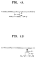
- FIGS. 4A and 4B Illustrate, respectively, apparatus for adjusting the tilt of an optical disk and the skew of an optical pickup unit.
- the optical disc player includes a spindle 20 for rotatably driving the optical disc 10, a spindle base 40 for supporting the rotation of the spindle 20, and a tilting unit 30 for adjusting the tilt of the optical disc 10.
- the tilt adjuster 160 applies a drive signal, of an appropriate size, to the tilting unit and adjusts the tilt of the optical disc.
- the optical pickup units 110 and 210 may include a light source 211, an actuator 212, and first and second focusing coils 213 and 214.
- additional hardware such as a beam splitter for adjusting the direction of the laser beam and an objective lens for focusing the laser beam, are not Illustrated.
- the light source 211 can usually be a laser diode.
- the actuator 212 can be combined with the light source 211 and move together with the light source 211, in the horizontal direction, to track the beam spot.
- the first and second focusing coils 213 and 214 can be connected to both sides of the actuator 212.
- the skew adjuster 260 can apply a drive signal of a predetermined size to the first and second focusing coils 213 and 214, respectively, to adjust the skew of the optical pickup units 110 and 210.
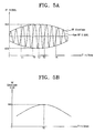
- FIGS. 5A and 5B illustrate, respectively, a Raw RF signal reproduced, from the corresponding signal processors 120 and 220, and the envelope size of the Raw RF signal.
- the Raw RF signal changes with respect to the changes in the tilt or skew (hereinafter referred to as "tilt/skew"), and the envelope is obtained by comparing maximum values and minimum values at each frequency of the Raw RF signal.
- tilt/skew the tilt/skew
- FIG. 5B Illustrates the relationship between the envelope size and the tilt/skew.
- FIG. 6 illustrates a flow chart for a tilt/skew compensation method, according to an embodiment of the present Invention.
- the controllers 140 and 240 can set the tilt/skew to equal ' ⁇ ', as an initial value (S610), and control the optical pickup units 110 and 210 to reproduce data (S620).
- the reproduced data from the optical pickup units 110 and 210 can be extracted by the signal processors 120 and 220, respectively, and goes through a process (e.g., sampling) (5630).
- the signal size computing units 130 and 230 can compute the envelope size of the RF signal, and store the computed envelope sized in the memories 150 and 250 (S640).
- the controllers 140 and 240 can check a maximum value of the envelope sizes of the RF signal in the memories 150 and 250 (S670).
- the tilt/skew corresponding to the maximum value of the envelope size can be designated as the optimal tilt/skew (S680).
- the optimal tilt/skew with the least jitter can be obtained.
- FIG. 7 is a flow chart illustrating a method for computing the envelope size of an RF signal, according to an embodiment of the present invention. Referring to FIG. 7, when a Raw RF signal is detected from the optical disc 10 (S710) the signal processor performs the equalizing and sampling on the signal (S720, S730).
- the difference between sample values at the maximum RF signal and the minimum RF signal can be computed (S740), and the Information on a present tilt/skew and the difference can be stored in the memories 150 and 250 (S750).
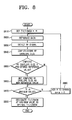
- FIG. 8 is a flow chart illustrating a tilt/skew compensation method, according to another embodiment of the present invention.
- the controller sets tilt/skew to equal ⁇ (S810), computes the envelope size of an RF signal that Is detected during the reproduction of the data, and stores the envelope size (S820, S830, S840).
- the computed envelope size, from the present tilt/skew is then compared with a pre-stored reference value (S850). If it turns out that the presently computed envelope size is greater than the reference value, the present envelope size is set as a new reference value (S860). On the other hand, if it turns out that the presently computed envelope size is smaller than the reference value, the reference value is kept (S850).
- the controllers 140 and 240 can then repeat the above-described comparison procedures, while changing the tilt/skew within the predetermined range (S870, S880), and if a final reference value is set, the controllers 140 and 240 can determine the optimal tilt/skew using the tilt/skew corresponding to the reference value (S890). Particularly, in embodiments of the present invention, it is not necessary to store all of the envelope sizes over the entire range of the tilt/skew. Thus, the storage capacity of the memories 150 and 250 can be preserved to a great degree.
- embodiments of the present invention can also be implemented through computer readable code/instructions in/on a medium, e.g., a computer readable medium.
- the medium can correspond to any medium/media permitting the storing and/or transmission of the computer readable code.
- the computer readable code can be recorded/transferred on a medium in a variety of ways, with examples of the medium including magnetic storage media (e.g., ROM, floppy disks, hard disks, etc.), optical recording media (e.g., CD-ROMs, or DVDs), and storage/transmission media such as carrier waves, as well as through the Internet, for example.
- the media may also be a distributed network, so that the computer readable code Is stored/transferred and executed in a distributed fashion.
Landscapes
- Optical Recording Or Reproduction (AREA)
Abstract
Description
- Embodiments of the present invention relate in general to recording and/or reproducing apparatuses, e.g., an optical disc player, compensating for a tilt/skew, and method and media thereof. More specifically, but not exclusively, embodiments of the present Invention relate to an optical disc player compensating for a tilt/skew using an RF envelope detected from an optical disc, and methods and media thereof.
- As computers become prevalent in every part of our daily lives, the need has increased for as many peripherals and components as possible to increase the effectiveness and the performance of computers. Particularly, diverse types of auxiliary storage media are available, e.g., storing programs and stored data of the computer's memory in the event of computer power supply cut-off. Typical examples of the auxiliary storage media include magnetic storage media and optical disc storage media.
- The magnetic storage media, such as floppy disks and hard disks use a magnetic field to record data. However, the capacities of such magnetic storage media are so small that multiple magnetic storage media have to be used to store multimedia data now being generated. To increase the storage capacity of the magnetic disc, an optical disc (or a laser disc) with a relatively large storage capacity and high data retrieval speed has been developed and is now in use. The optical discs can include CD-ROMs and DVDs (digital video discs), for example.
- The optical disc is a recording medium recording data thereon or for playing back (reproducing) data therefrom by applying an optical operation. The optical disc has a support base on which data (i.e., data bits '1' or '0') is recorded by laser beams in pit trains on a track, for example. This data can generally accessed or retrieved by detecting a reflected light or an incident light obtained from the illumination with the laser beam, for example.
- To record/reproduce data stably on/from a high-density optical disc such as a DVD-ROM, the optical axis of the laser beam emitted onto the optical disc is usually desired to be perpendicular to the surface of the optical disc, that is, the declination angle of the optical axis is perpendicular to the surface of the optical disc. In practice, however, the surface of the disc is sometimes distorted or tilted, and a skew may occur to the optical pickup unit that emits the laser beam. When this occurs, the emission angle of the laser beam (signal) is not perpendicular. As a result, jitter occurs during the reproduction of data. Jitter is a time-based error caused by the vibration of data signals reproduced from the recording medium. Jitter can cause deteriorations in the processing capability of a control unit or a substantial loss of data in a synchronized network due to the lack of processing capability for reproduced signals. Therefore, it is desirable to reduce the amount of jitter as much as possible.
- FIG. 1 is a graph illustrating a relationship between the amount of jitter and the tilt/skew in a related art optical disc player. Here, to set an optical tilt/skew the amount of jitter is measured In a given range while changing the tilt/skew. The changes in the amount of jitter is reflected In the graph of FiG. 1. Therefore, it is possible to adjust the tilt value or the skew value to the point that the jitter is reduced to a minimum,
- However, for the compensation of the tilt/skew in the related art optical disc player the jitter measurement had to be done separately. In other words, a certain amount of data was needed to measure jitter, and for a more reliable measurement the same Interval was played back repeatedly, which consequently caused delays in data reproduction. In addition, because the jitter had to be computed after processing the reproduced data, the operation itself was a burden. And most importantly, an operation system for accurate measurement of jitter was necessary, and the normal function could be performed only for the jitter measurement with high discriminability.
- In the meantime, Japanese Patent Laid-Open Publication Nos, 9-212891 and 9-245357 disclose methods for compensating a tilt using a separate tilt sensor. According to these disclosures, the tilt of the optical pickup unit is detected not through the operation of jitter but with the help of the tilt sensor. However, using the tilt sensor means that the light source cannot be Installed at the same position with the tilt sensor. As a result, an accurate tilt angle cannot be obtained, and the entire size of the optical disc player is increased.
- According to a first aspect, the present invention provides an optical disc player recording and/or reproducing data recorded on an optical disc, including an optical pickup unit to emit a laser beam to a surface of the optical disc and extract an RF signal, from the laser beam reflected from the surface of the optical disc, corresponding to the data, a signal size computing unit to compute an envelope size of the RF signal, a tilt adjuster to adjust a tilt of the optical disc, and a controller to designate a tilt of the optical disc at a maximum envelope size as an optimal tilt, and to control the tilt adjuster to change a present tilt of the optical disc based on the optimal tilt.
- The optical disc player may further include a memory to store the designated tilt and the computed envelope size corresponding to the designated tilt, The controller may compute the envelope size while changing the present tilt, within a predetermined range, store the envelope size in the memory, extract from the memory the designated tilt, and designate the designated tilt as the optimal tilt, In addition, the computed envelope sizes may not be stored together.
- According to a second aspect, the present Invention provides an optical disc player for recording and/or reproducing data recorded on an optical disc. Including an optical pickup unit to emit a laser beam to a surface of the optical disc and extract an RF signal, from the laser beam reflected from the surface of the opiicai disc, corresponding to the data, a signal size computing unit to compute an envelope size of the RF signal, a skew adjuster to adjusts a skew of the optical pickup, and a controller to designate the skew of the optical pickup at a maximum envelope size as an optimal skew, and to control the skew adjuster to change a present skew of the optical pickup based on the optimal skew.
- The optical disc player may include a memory to store the designated skew and the computed envelope size corresponding to the designated skew. The controller may compute the envelope size while changing the current skew within a predetermined range, store the envelope size in the memory, extract from the memory the designated skew, and designate the designated skew at the maximum envelope size as the optimal skew.
- In addition, the skew adjuster may also apply a drive signal to at least one focusing coil to adjust skew of the optical pickup.
- According to a third aspect, the present invention provides a method for compensating a tilt of an optical disc player for recording and/or reproducing data recorded on an optical disc, including emitting a laser beam to a surface of the optical disc and extracting an RF signal, from the laser beam reflected from the surface of the optical disc, corresponding to the data, computing an envelope size of the RF signal, adjusting a tilt of the optical disc within a predetermined range, and repeating the emitting of the laser beam, extracting of the RF signal, and the computing of the envelope size, and designating the tilt of the optical disc at a maximum envelope size as an optimal tilt, and changing a present tilt of the optical disc based on the optimal tilt.
- The method may include storing each computed envelope size of the RF signal.
- According to a fourth aspect, the present invention provides a method for compensating a skew of an optical disc player for recording and/or reproducing data recorded on an optical disc, Including emitting a laser beam to a surface of the optical disc and extracting an RF signal, from the laser beam reflected from the surface of the optical disc, corresponding to the data, computing an envelope size of the RF signal, adjusting a skew of an optical pickup up the optical disc player, within a predetermined range, repeating the emitting of the laser beam, extracting of the RF signal, and the computing of the envelope size, and designating the skew of the optical pickup at a maximum envelope size as an optimal skew, and changing a present skew of the optical pickup based on the optimal skew.
- The adjusting of skew of the optical pickup may include applying a drive signal to at least one focusing coil.
- To achieve the above and/or other aspects and advantages, embodiments of the present invention Include media including computer readable code/instructions implementing embodiments of the present invention.
- Therefore, embodiments of the present invention provide an optical disc player compensating a tilt/skew using an envelope of an RF signal reproduced from the optical disc player, and methods and media thereof.
- Additional aspects and/or advantages of the invention will be set forth in part In the description which follows and, in part, will be apparent from the description, or may be learned by practice of the invention.
- For a better understanding of the Invention, and to show how embodiments of the same may be carried into effect, reference will now be made, by way of example, to the accompanying diagrammatic drawings in which:
- FIG. 1 illustrates changes in jitter for setting an optimal tilt/skew in a related art optical disc player;
- FIG. 2 illustrates a schematic block diagram for an optical disc player, according to an embodiment of the present invention;
- FIG. 3 illustrates a schematic block diagram for an optical disc player, according to another embodiment of the present Invention;
- FIGS. 4A and 4B illustrate, respectively, apparatuses for adjusting the tilt of an optical disk and the skew of an optical pickup unit, according to embodiments of the present invention;
- FIG. 5A illustrates an RF signal reproduced from an optical disc and an RF envelope thereof, according to an embodiment of the present invention;
- FIG. 5B illustrates a relationship between an envelope size of an RF signal and a tilt/skew, according to an embodiment of the present invention;
- FIG. 6 illustrates a flow chart for a tilt/skew compensation method, according to an embodiment of the present invention:
- FIG. 7 illustrates a flow chart for a method for computing an envelope size of an RF signal, according to an embodiment of the present invention; and
- FIG. 8 illustrates a flow chart for a tilt/skew compensation method, according to another embodiment of the present invention.
- Reference will now be made in detail to embodiments of present invention, examples of which are illustrated In the accompanying drawings, wherein like reference numerals refer to the like elements throughout. The embodiments are described below to explain the present invention by referring to the figures.
- FIG. 2 illustrates a schematic block diagram of an optical disc player, according to an embodiment of the present invention. As shown in FIG. 2, the optical disc player may include an
optical pickup unit 110, asignal processor 120, a signalsize computing unit 130, acontroller 140, amemory 150 and atilt adjuster 160. - The
optical pickup unit 110 emits a laser beam to the surface of the optical disc to record/reproduce data. That is, theoptical pickup unit 110 can emit the laser beam to a track on the surface of the optical disc to form a pit train, and records a data bit '1' or '0' thereon, for example, or reproduces an RF (Radio Frequency) signal corresponding to data on the surface of the optical disc. To this end, theoptical pickup unit 110 can include a light source emitting a laser beam, and an actuator that adjusts tracking and focusing of theoptical pickup unit 110. More details on the make up of theoptical pickup unit 110 will be described later with reference to FIG 38. - Recorded data can be accessed by emitting the laser beam to the surface of the optical disc. Then the laser beam is reflected by the recorded data on the track, the reflected beam is detected, and the detection of the reflected beam Is output as a RF signal. This RF signal is then sent to the
signal processor 120 where it is equalized, sampled and converted to digital data. - The signal
size computing unit 130 can compute the envelope size of a sample RF signal from thesignal processor 120. The envelope size is the difference between a maximum RF signal and a minimum RF signal being sampled. - The
tilt adjuster 160 can adjust the declination angle (i.e., the tilt angle) of the optical disc. More details on the tilt adjustment will be provided below. - The
controller 140 can control thetilt adjuster 160 and theoptical pickup unit 110 to change the tilt, within a predetermined range, and reproduce data. As described above, when the data is reproduced from the optical disc, the signalsize computing unit 130 computes the envelope size of the RF signal. The envelope size is then recorded in thememory 150. - In addition, the
controller 140 detects the maximum envelope size, and designates the tilt at the maximum envelope size as an optimal tilt. In other words, the RF signal changes according to the changes in the tilt, and the envelope size of the RF signal has a maximum value when the optical axis of the laser beam emitted from theoptical pickup unit 110 is perpendicular to the surface of the optical disc. Therefore, thecontroller 140 designates the tilt at the maximum envelope size as the optimal tilt. Later, thecontroller 140 controls thetilt adjuster 160 to adjust to the recognized optimal tilt. In this manner, the tilt of the optical disc can be compensated to the optimal value. - FIG. 3 illustrates a schematic block diagram of an optical disc player, according to another embodiment of the present invention. As shown in FIG. 3, the optical disc player includes an
optical pickup unit 210, asignal processor 220, a signalsize computing unit 230, acontroller 240, amemory 250, and askew adjuster 260. - The
skew adjuster 260 can adjust the skew of theoptical pickup unit 110. As discussed above, thecontroller 240 controls theskew adjuster 260 to adjust the skew within a predetermined range, and computes the envelope size of an RF signal. As such, the controller detects a maximum envelope size, and designates the skew, at the maximum envelope size, as an optimal skew. Accordingly, thecontroller 240 can control theskew adjuster 260 to compensate for the skew of theoptical pickup unit 210, as the optimal value. Other components, except for theskew adjuster 260 and thecontroller 240, are identical with those in the FIG. 2. - Also, the make up and operational principles of the embodiments shown in FIGS. 2 and 3, respectively, are similar to each other, so they will be further explained collectively hereinafter.
- FIGS. 4A and 4B Illustrate, respectively, apparatus for adjusting the tilt of an optical disk and the skew of an optical pickup unit. As shown in FIG. 4A, the optical disc player includes a
spindle 20 for rotatably driving theoptical disc 10, a spindle base 40 for supporting the rotation of thespindle 20, and atilting unit 30 for adjusting the tilt of theoptical disc 10. Accordingly, thetilt adjuster 160 applies a drive signal, of an appropriate size, to the tilting unit and adjusts the tilt of the optical disc. - Referring to FIG. 4B, the
optical pickup units optical disc 10, may include alight source 211, anactuator 212, and first and second focusingcoils light source 211 can usually be a laser diode. Theactuator 212 can be combined with thelight source 211 and move together with thelight source 211, in the horizontal direction, to track the beam spot. The first and second focusingcoils actuator 212. When a drive signal is applied thereto, the focusingcoils actuator 212. As a result thereof, the vertical position of the light source is adjusted, which in turn makes the focusingcoils skew adjuster 260 can apply a drive signal of a predetermined size to the first and second focusingcoils optical pickup units - FIGS. 5A and 5B illustrate, respectively, a Raw RF signal reproduced, from the
corresponding signal processors - FIG. 5B Illustrates the relationship between the envelope size and the tilt/skew. Referring to FIG. 5B, provided that the data was reproduced while the tilt/skew changed only a small amount, the RF signal with the maximum envelope size was detected at T0. Accordingly, the
controllers tilt adjuster 160 or theskew adjuster 260 to make the tilt/skew value = T0, thereby obtaining the optimal tilt/skew. - FIG. 6 illustrates a flow chart for a tilt/skew compensation method, according to an embodiment of the present Invention. Referring to FIG. 6, first the
controllers optical pickup units - The reproduced data from the
optical pickup units signal processors size computing units memories 150 and 250 (S640). - The
controllers controllers controllers controllers - If all the tilt/skew values are computed/stored, the
controllers memories 150 and 250 (S670). - Then the tilt/skew corresponding to the maximum value of the envelope size can be designated as the optimal tilt/skew (S680). In other words, the optimal tilt/skew with the least jitter can be obtained.
- FIG. 7 is a flow chart illustrating a method for computing the envelope size of an RF signal, according to an embodiment of the present invention. Referring to FIG. 7, when a Raw RF signal is detected from the optical disc 10 (S710) the signal processor performs the equalizing and sampling on the signal (S720, S730).
- Next, the difference between sample values at the maximum RF signal and the minimum RF signal can be computed (S740), and the Information on a present tilt/skew and the difference can be stored in the
memories 150 and 250 (S750). - FIG. 8 is a flow chart illustrating a tilt/skew compensation method, according to another embodiment of the present invention. Referring to FIG. 8, the controller sets tilt/skew to equal α (S810), computes the envelope size of an RF signal that Is detected during the reproduction of the data, and stores the envelope size (S820, S830, S840). The computed envelope size, from the present tilt/skew, is then compared with a pre-stored reference value (S850). If it turns out that the presently computed envelope size is greater than the reference value, the present envelope size is set as a new reference value (S860). On the other hand, if it turns out that the presently computed envelope size is smaller than the reference value, the reference value is kept (S850).
- The
controllers controllers memories - In addition to the above described embodiments, embodiments of the present invention can also be implemented through computer readable code/instructions in/on a medium, e.g., a computer readable medium. The medium can correspond to any medium/media permitting the storing and/or transmission of the computer readable code.
- The computer readable code can be recorded/transferred on a medium in a variety of ways, with examples of the medium including magnetic storage media (e.g., ROM, floppy disks, hard disks, etc.), optical recording media (e.g., CD-ROMs, or DVDs), and storage/transmission media such as carrier waves, as well as through the Internet, for example. The media may also be a distributed network, so that the computer readable code Is stored/transferred and executed in a distributed fashion.
- In conclusion, with embodiments of the present invention, it possible to obtain an optimal tilt/skew using an envelope size of a detected RF signal. As such, Jitter can be minimized. Since the envelope size of the RF signal is used for compensation of the focusing error or the tracking error, components for tilt/skew compensation only are no longer required. As a result, no additional costs are incurred. Moreover, because a separate operation process for extracting the jitter Is no longer required, the required time for data reproduction can be reduced.
- Although a few embodiments of the present Invention have been shown and described, it would be appreciated by those skilled in the art that changes may be made in these embodiments without departing from the principles and spirlt of the invention, the scope of which is defined in the claims and their equivalents.
- Attention is directed to all papers and documents which are filed concurrently with or previous to this specification in connection with this application and which are open to public inspection with this specification, and the contents of all such papers and documents are Incorporated herein by reference.
- All of the features disclosed in this specification (including any accompanying claims, abstract and drawings), and/or all of the steps of any method or process so disclosed, may be combined in any combination, except combinations where at least some of such features and/or steps are mutually exclusive.
- Each feature disclosed in this specification (including any accompanying claims, abstract and drawings) may be replaced by alternative features serving the same, equivalent or similar purpose, unless expressly stated otherwise. Thus, unless expressly stated otherwise, each feature disclosed is one example only of a generic series of equivalent or similar features.
- The invention is not restricted to the details of the foregoing embodiment(s). The invention extends to any novel one, or any novel combination, of the features disclosed in this specification (including any accompanying claims, abstract and drawings), or to any novel one, or any novel combination, of the steps of any method or process so disclosed.
Claims (16)
- An optical disc player for recording and/or reproducing data recorded on an optical disc, comprising:an optical pickup unit (110) operable to emit a laser beam to a surface of the optical disc and to extract an RF signal from the laser beam reflected from the surface of the optical disc, corresponding to the data;a signal size computing unit (130) operable to compute an envelope size of the RF signal;a tilt adjuster (160) operable to adjust a tilt of the optical disc; anda controller (140) operable to designate a tilt of the optical disc at a maximum envelope size as an optimal tilt, and to control the tilt adjuster (160) to change a present tilt of the optical disc based on the optimal tilt.
- The optical disc player of claim 1, further comprising:a memory (150) operable to store the designated tilt and the computed envelope size corresponding to the designated tilt.
- The optical disc player of claim 2, wherein the controller (140) is operable to compute the envelope size while changing the present tilt, within a predetermined range, to store the envelope size in the memory, to extract from the memory the designated tilt, and to designate the designated tilt as the optimal tilt.
- The optical disc player of claim 2 or 3, wherein not all computed envelope sizes are stored together.
- An optical disc player for recording and/or reproducing data recorded on an optical disc, comprising:an optical pickup unit (210) operable to emit a laser beam to a surface of the optical disc and to extract an RF signal, from the laser beam reflected from the surface of the optical disc, corresponding to the data;a signal size computing unit (230) operable to compute an envelope size of the RF signal;a skew adjuster (260) operable to adjust a skew of the optical pickup (210); anda controller (240) operable to designate the skew of the optical pickup at a maximum envelope size as an optimal skew, and to control the skew adjuster (260) to change a present skew of the optical pickup based on the optimal skew.
- The optical disc player of claim 5, further comprising:a memory (250) operable to store the designated skew and the computed envelope size corresponding to the designated skew.
- The optical disc player of claim 6, wherein the controller (240) is operable to compute the envelope size while changing the current skew within a predetermined range, to store the envelope size in the memory, extracts from the memory the designated skew, and to designate the designated skew at the maximum envelope size as the optimal skew.
- The optical disc player of claim 6 or 7, wherein not all computed envelope sizes are stored together.
- The optical disc player of any of claims 5-7, wherein the skew adjuster (260) is operable to apply a drive signal to at least one focusing coil (213, 214) to adjust skew of the optical pickup.
- A method for compensating a tilt of an optical disc player for recording and/or reproducing data recorded on an optical disc, comprising:emitting a laser beam to a surface of the optical disc and extracting (S630) an RF signal, from the laser beam reflected from the surface of the optical disc, corresponding to the data;computing (S640) an envelope size of the RF signal;adjusting (S660) a tilt of the optical disc within a predetermined range, and repeating the emitting of the laser beam, extracting of the RF signal, and the computing of the envelope size; anddesignating (S680) the tilt of the optical disc at a maximum envelope size as an optimal tilt, and changing a present tilt of the optical disc based on the optimal tilt.
- The method of claim 10, further comprising:storing (S640) each computed envelope size of the RF signal.
- The method of claim 11, wherein not all computed envelope sizes are stored together.
- A method for compensating a skew of an optical disc player for recording and/or reproducing data recorded on an optical disc, comprising:emitting a laser beam to a surface of the optical disc and extracting (S710) an RF signal, from the laser beam reflected from the surface of the optical disc, corresponding to the data;computing an envelope size of the RF signal;adjusting a skew of an optical pickup up the optical disc player, within a predetermined range, repeating the emitting of the laser beam, extracting of the RF signal, and the computing of the envelope size ; anddesignating the skew of the optical pickup at a maximum envelope size as an optimal skew, and changing a present skew of the optical pickup based on the optimal skew.
- The method of claim 13, further comprising:storing each computed envelope size of the RF signal.
- The method of claim 14, wherein not all computed envelope sizes are stored together.
- The method of any of claims 13-15, wherein the adjusting of skew of the optical pickup comprises applying a drive signal to at least one focusing coil (213, 214).
Applications Claiming Priority (1)
| Application Number | Priority Date | Filing Date | Title |
|---|---|---|---|
| KR1020040052576A KR100613611B1 (en) | 2004-07-07 | 2004-07-07 | Optical disc player and method for correcting tilt / skew using envelope of high frequency signal |
Publications (1)
| Publication Number | Publication Date |
|---|---|
| EP1615210A1 true EP1615210A1 (en) | 2006-01-11 |
Family
ID=36076955
Family Applications (1)
| Application Number | Title | Priority Date | Filing Date |
|---|---|---|---|
| EP05254254A Withdrawn EP1615210A1 (en) | 2004-07-07 | 2005-07-06 | Optical disc player, method and media compensating for tilt/skew using RF envelope |
Country Status (4)
| Country | Link |
|---|---|
| US (1) | US7542386B2 (en) |
| EP (1) | EP1615210A1 (en) |
| KR (1) | KR100613611B1 (en) |
| CN (1) | CN100397504C (en) |
Citations (7)
| Publication number | Priority date | Publication date | Assignee | Title |
|---|---|---|---|---|
| JPH09212891A (en) | 1995-11-27 | 1997-08-15 | Ricoh Co Ltd | Optical head device |
| JPH09245357A (en) | 1996-01-24 | 1997-09-19 | Lg Electron Inc | Servo control device for optical disk recording / reproducing apparatus |
| US5881034A (en) * | 1996-08-20 | 1999-03-09 | Sony Corporation | Apparatus for driving objective lens |
| US6137754A (en) * | 1997-04-23 | 2000-10-24 | Pioneer Electronic Corporation | Search method for information record medium |
| US6587409B1 (en) * | 1999-05-24 | 2003-07-01 | Pioneer Corporation | Tilt servo apparatus for optical disc recording/playing apparatus |
| US20030179665A1 (en) * | 2002-03-19 | 2003-09-25 | Nec Corporation | Optical disk drive having a tilt compensator |
| US6680886B1 (en) * | 1999-04-14 | 2004-01-20 | Pioneer Corporation | Liquid crystal tilt servo apparatus |
Family Cites Families (19)
| Publication number | Priority date | Publication date | Assignee | Title |
|---|---|---|---|---|
| MY132591A (en) | 1995-10-26 | 2007-10-31 | Sony Corp | Optical disc apparatus. |
| JP3545196B2 (en) | 1998-03-20 | 2004-07-21 | パイオニア株式会社 | Tilt servo controller |
| KR20000026832A (en) * | 1998-10-23 | 2000-05-15 | 구자홍 | Method for controlling tilt |
| JP2000132855A (en) * | 1998-10-27 | 2000-05-12 | Matsushita Electric Ind Co Ltd | Optical information recording / reproducing device |
| KR20000033029A (en) | 1998-11-19 | 2000-06-15 | 전주범 | Circuit for generating stable focus ok signal |
| KR20000050358A (en) | 1999-01-07 | 2000-08-05 | 구자홍 | An apparatus for controlling the reproducing speed of an optical disc |
| JP2000311350A (en) | 1999-04-23 | 2000-11-07 | Sony Corp | Automatic gain control device, automatic gain control method, and optical disk device |
| KR100587269B1 (en) * | 1999-06-02 | 2006-06-08 | 엘지전자 주식회사 | Tilt Control Method |
| KR20020039504A (en) * | 2000-11-21 | 2002-05-27 | 구자홍 | Method and apparatus thereof for controlling tilt |
| KR20020039505A (en) * | 2000-11-21 | 2002-05-27 | 구자홍 | Tilt controlling method and apparatus |
| KR100375223B1 (en) * | 2000-11-21 | 2003-03-07 | 엘지전자 주식회사 | Apparatus for optical pick-up and methode for tilt controlling of optical pick-up |
| KR100846777B1 (en) | 2002-07-05 | 2008-07-16 | 삼성전자주식회사 | Mirror signal detection circuit for optical disk device and method thereof |
| KR100472469B1 (en) * | 2002-08-17 | 2005-03-10 | 삼성전자주식회사 | Method for correcting tilt in the disc drive and method thereof |
| JP3975139B2 (en) * | 2002-08-30 | 2007-09-12 | パイオニア株式会社 | Tilt correction device and tilt correction method |
| JP2004192754A (en) * | 2002-12-13 | 2004-07-08 | Sanyo Electric Co Ltd | Tilt control method for optical disk recording / reproducing device |
| JP4097257B2 (en) * | 2003-01-31 | 2008-06-11 | 株式会社リコー | Tilt correction method, tilt correction apparatus, and optical disc apparatus |
| US7328035B2 (en) * | 2003-07-08 | 2008-02-05 | Motorola, Inc. | Method and apparatus for reducing paging-related delays |
| TWI270874B (en) * | 2003-08-11 | 2007-01-11 | Mediatek Inc | Method for calibrating tilt control value of a pickup |
| TWI229920B (en) * | 2004-04-12 | 2005-03-21 | Phoenix Prec Technology Corp | Electrical connection structure of embedded chip and method for fabricating the same |
-
2004
- 2004-07-07 KR KR1020040052576A patent/KR100613611B1/en not_active Expired - Fee Related
-
2005
- 2005-07-06 EP EP05254254A patent/EP1615210A1/en not_active Withdrawn
- 2005-07-07 CN CNB2005100832386A patent/CN100397504C/en not_active Expired - Fee Related
- 2005-07-07 US US11/175,691 patent/US7542386B2/en active Active
Patent Citations (7)
| Publication number | Priority date | Publication date | Assignee | Title |
|---|---|---|---|---|
| JPH09212891A (en) | 1995-11-27 | 1997-08-15 | Ricoh Co Ltd | Optical head device |
| JPH09245357A (en) | 1996-01-24 | 1997-09-19 | Lg Electron Inc | Servo control device for optical disk recording / reproducing apparatus |
| US5881034A (en) * | 1996-08-20 | 1999-03-09 | Sony Corporation | Apparatus for driving objective lens |
| US6137754A (en) * | 1997-04-23 | 2000-10-24 | Pioneer Electronic Corporation | Search method for information record medium |
| US6680886B1 (en) * | 1999-04-14 | 2004-01-20 | Pioneer Corporation | Liquid crystal tilt servo apparatus |
| US6587409B1 (en) * | 1999-05-24 | 2003-07-01 | Pioneer Corporation | Tilt servo apparatus for optical disc recording/playing apparatus |
| US20030179665A1 (en) * | 2002-03-19 | 2003-09-25 | Nec Corporation | Optical disk drive having a tilt compensator |
Also Published As
| Publication number | Publication date |
|---|---|
| US7542386B2 (en) | 2009-06-02 |
| CN1734594A (en) | 2006-02-15 |
| CN100397504C (en) | 2008-06-25 |
| US20060007831A1 (en) | 2006-01-12 |
| KR100613611B1 (en) | 2006-08-21 |
| KR20060003615A (en) | 2006-01-11 |
Similar Documents
| Publication | Publication Date | Title |
|---|---|---|
| US7978581B2 (en) | Multi-layered high-density recording medium and optical power adjusting method therefor | |
| US20050141363A1 (en) | Optical disc apparatus, an optical disc method, and a semiconductor integrated circuit | |
| US20040085869A1 (en) | Optical disk apparatus | |
| US8391112B2 (en) | Optical disk apparatus, control method, and program | |
| EP1615210A1 (en) | Optical disc player, method and media compensating for tilt/skew using RF envelope | |
| US20080019236A1 (en) | Method for measuring a tilt control value of a pickup head in an optical disk drive | |
| US7940616B2 (en) | Optical disk apparatus and tilt control method thereof | |
| CN1327422C (en) | Optical disc drive device and tilt correction method for its optical pickup head | |
| JP2002251739A (en) | Phase compensation method and optical storage device | |
| JP2000222747A (en) | Optical disk device and servo parameter adjusting device | |
| TW200419553A (en) | Recording and reproduction apparatus | |
| JP2005235348A (en) | Tilt compensation device, tilt compensation method, and optical recording / reproducing device using the same | |
| KR100652951B1 (en) | Optical disk device capable of skew correction and its method | |
| US7626899B2 (en) | Method for obtaining an optimum focusing point of an optical pickup unit and a servo system of an optical disk drive using this method | |
| US8085629B2 (en) | Optical focus error offset to reduce radial to vertical crosstalk | |
| KR20080027887A (en) | Smart adjustment of 4-wire 3-dimensional (3D) actuator | |
| KR20020023659A (en) | Recording and playback apparatus, recording and playback method and recording medium | |
| JP2005071545A (en) | Optical disc apparatus and tracking balance adjustment method | |
| KR100315633B1 (en) | Optical pickup control method of multi-layer recording type digital video disc player | |
| KR20040048610A (en) | Method and apparatus for compensating disc tilt | |
| KR20040049463A (en) | Method and apparatus for compensating disc tilt | |
| JP2000020991A (en) | Optical disk skew control method and optical disk device | |
| JP2006004533A (en) | Tilt correction method and optical disc apparatus | |
| JP2005050410A (en) | Optical disk device | |
| JP2008524760A (en) | How to measure and optimize radial vertical crosstalk |
Legal Events
| Date | Code | Title | Description |
|---|---|---|---|
| PUAI | Public reference made under article 153(3) epc to a published international application that has entered the european phase |
Free format text: ORIGINAL CODE: 0009012 |
|
| AK | Designated contracting states |
Kind code of ref document: A1 Designated state(s): AT BE BG CH CY CZ DE DK EE ES FI FR GB GR HU IE IS IT LI LT LU LV MC NL PL PT RO SE SI SK TR |
|
| AX | Request for extension of the european patent |
Extension state: AL BA HR MK YU |
|
| 17P | Request for examination filed |
Effective date: 20060627 |
|
| AKX | Designation fees paid |
Designated state(s): GB |
|
| REG | Reference to a national code |
Ref country code: DE Ref legal event code: 8566 |
|
| 17Q | First examination report despatched |
Effective date: 20061023 |
|
| 17Q | First examination report despatched |
Effective date: 20061023 |
|
| STAA | Information on the status of an ep patent application or granted ep patent |
Free format text: STATUS: THE APPLICATION IS DEEMED TO BE WITHDRAWN |
|
| 18D | Application deemed to be withdrawn |
Effective date: 20090203 |