EP1615155A2 - Radio IC tag system - Google Patents
Radio IC tag system Download PDFInfo
- Publication number
- EP1615155A2 EP1615155A2 EP04257389A EP04257389A EP1615155A2 EP 1615155 A2 EP1615155 A2 EP 1615155A2 EP 04257389 A EP04257389 A EP 04257389A EP 04257389 A EP04257389 A EP 04257389A EP 1615155 A2 EP1615155 A2 EP 1615155A2
- Authority
- EP
- European Patent Office
- Prior art keywords
- radio
- tag
- tag reader
- value
- unit
- Prior art date
- Legal status (The legal status is an assumption and is not a legal conclusion. Google has not performed a legal analysis and makes no representation as to the accuracy of the status listed.)
- Withdrawn
Links
Images







Classifications
-
- G—PHYSICS
- G06—COMPUTING OR CALCULATING; COUNTING
- G06K—GRAPHICAL DATA READING; PRESENTATION OF DATA; RECORD CARRIERS; HANDLING RECORD CARRIERS
- G06K17/00—Methods or arrangements for effecting co-operative working between equipments covered by two or more of main groups G06K1/00 - G06K15/00, e.g. automatic card files incorporating conveying and reading operations
-
- B—PERFORMING OPERATIONS; TRANSPORTING
- B42—BOOKBINDING; ALBUMS; FILES; SPECIAL PRINTED MATTER
- B42D—BOOKS; BOOK COVERS; LOOSE LEAVES; PRINTED MATTER CHARACTERISED BY IDENTIFICATION OR SECURITY FEATURES; PRINTED MATTER OF SPECIAL FORMAT OR STYLE NOT OTHERWISE PROVIDED FOR; DEVICES FOR USE THEREWITH AND NOT OTHERWISE PROVIDED FOR; MOVABLE-STRIP WRITING OR READING APPARATUS
- B42D25/00—Information-bearing cards or sheet-like structures characterised by identification or security features; Manufacture thereof
- B42D25/30—Identification or security features, e.g. for preventing forgery
- B42D25/305—Associated digital information
-
- G—PHYSICS
- G06—COMPUTING OR CALCULATING; COUNTING
- G06K—GRAPHICAL DATA READING; PRESENTATION OF DATA; RECORD CARRIERS; HANDLING RECORD CARRIERS
- G06K19/00—Record carriers for use with machines and with at least a part designed to carry digital markings
- G06K19/06—Record carriers for use with machines and with at least a part designed to carry digital markings characterised by the kind of the digital marking, e.g. shape, nature, code
- G06K19/067—Record carriers with conductive marks, printed circuits or semiconductor circuit elements, e.g. credit or identity cards also with resonating or responding marks without active components
- G06K19/07—Record carriers with conductive marks, printed circuits or semiconductor circuit elements, e.g. credit or identity cards also with resonating or responding marks without active components with integrated circuit chips
- G06K19/0716—Record carriers with conductive marks, printed circuits or semiconductor circuit elements, e.g. credit or identity cards also with resonating or responding marks without active components with integrated circuit chips at least one of the integrated circuit chips comprising a sensor or an interface to a sensor
-
- G—PHYSICS
- G06—COMPUTING OR CALCULATING; COUNTING
- G06K—GRAPHICAL DATA READING; PRESENTATION OF DATA; RECORD CARRIERS; HANDLING RECORD CARRIERS
- G06K7/00—Methods or arrangements for sensing record carriers, e.g. for reading patterns
- G06K7/0008—General problems related to the reading of electronic memory record carriers, independent of its reading method, e.g. power transfer
-
- G—PHYSICS
- G06—COMPUTING OR CALCULATING; COUNTING
- G06K—GRAPHICAL DATA READING; PRESENTATION OF DATA; RECORD CARRIERS; HANDLING RECORD CARRIERS
- G06K7/00—Methods or arrangements for sensing record carriers, e.g. for reading patterns
- G06K7/10—Methods or arrangements for sensing record carriers, e.g. for reading patterns by electromagnetic radiation, e.g. optical sensing; by corpuscular radiation
- G06K7/10009—Methods or arrangements for sensing record carriers, e.g. for reading patterns by electromagnetic radiation, e.g. optical sensing; by corpuscular radiation sensing by radiation using wavelengths larger than 0.1 mm, e.g. radio-waves or microwaves
- G06K7/10019—Methods or arrangements for sensing record carriers, e.g. for reading patterns by electromagnetic radiation, e.g. optical sensing; by corpuscular radiation sensing by radiation using wavelengths larger than 0.1 mm, e.g. radio-waves or microwaves resolving collision on the communication channels between simultaneously or concurrently interrogated record carriers.
Definitions
- a vibration monitoring system embodying another aspect of the present invention monitors vibrations of a commodity while the commodity is being transported.
- the vibration monitoring system includes a radio IC tag reader writer, a radio IC tag attached to the commodity, and a vibration sensor that measures vibrations of the commodity or around the commodity.
- the radio IC tag reader writer includes a receiving unit that receives from a vibration sensor a value that represents vibrations measured by the vibration sensor; a judging unit that judges whether the value received by the receiving unit exceeds a predetermined threshold; and a writing unit that writes the value in the radio IC tag if the judging unit judges that the value exceeds the predetermined threshold.
- the temperature sensor 150 is a sensor incorporated in the RFID tag reader writer 100 and measures temperature in the freezing warehouse, in which the RFID tag reader writer 100 is set, based on an instruction from the temperature processing unit 140.
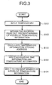
- FIG. 3 is a flowchart of the processing procedure of the temperature writing processing by the RFID tag reader writer 100 according to the first embodiment.
- the host PC 310 is a computer that receives temperature measured by the RFID tag reader writer 500 and instructs the RFID tag reader writer 500 to write the temperature in an RFID tag. However, unlike the host PC 300, the host PC 310 includes a data storing unit 311.
- the temperature monitoring system for fresh food is explained.
- an on-vehicle vibration monitoring system which uses an RFID tag reader writer to which a GP sensor and a vibration sensor are connected, will be explained.
- this on-vehicle vibration monitoring system includes an RFID tag reader writer 800 and the RFID tag 900 attached to a melon 30 and monitors a vibration amount of the melon 30 transported by a vehicle-mounted container. Note that, here, for convenience of explanation, only one melon 30 and only one RFID tag 900 are shown, this vibration monitoring system monitors vibration amounts of melons in plural boxes attached with RFID tags.
Landscapes
- Engineering & Computer Science (AREA)
- Physics & Mathematics (AREA)
- General Physics & Mathematics (AREA)
- Theoretical Computer Science (AREA)
- Toxicology (AREA)
- Artificial Intelligence (AREA)
- Computer Vision & Pattern Recognition (AREA)
- Health & Medical Sciences (AREA)
- Computer Hardware Design (AREA)
- Microelectronics & Electronic Packaging (AREA)
- General Health & Medical Sciences (AREA)
- Electromagnetism (AREA)
- Computer Networks & Wireless Communication (AREA)
- Arrangements For Transmission Of Measured Signals (AREA)
- Cash Registers Or Receiving Machines (AREA)
- Measuring Temperature Or Quantity Of Heat (AREA)
- Control Of Vending Devices And Auxiliary Devices For Vending Devices (AREA)
- Credit Cards Or The Like (AREA)
Abstract
Description
- The present invention relates to radio IC tags.
- In recent years, establishment of a system using a Radio Frequency Identification (RFID) tag (radio IC tag) has been in progress in various fields (see "RFID technology", retrieved on June 21, 2004, Internet URL:http://itpro.nikkeibp.co.jp/rfid/). The RFID tags are used in various field, such as logistic and apparel, as a replacement of barcodes.
- Embodiments of the present invention seek to provide a RFID tag that is capable of measuring or monitoring conditions around a commodity to which the RFID tag is attached.
- A radio IC tag reader writer, which reads out data from a radio IC tag and writes data in the radio IC tag using radio, embodying a first aspect of the present invention includes a receiving unit that receives from a sensor a value of a parameter measured by the sensor; and a writing unit that writes the value in the radio IC tag.
- A radio IC tag system embodying another aspect of the present invention is constituted by connecting at least one first radio IC tag reader writer with a plurality of second radio IC tag reader writers via a network. Each of the first radio IC tag reader writer and the second radio IC tag reader writers has a corresponding radio IC tag. The first radio IC tag reader writer includes a receiving unit that receives from a sensor a value of a parameter measured by the sensor; a first writing unit that writes the value in the corresponding radio IC tag; and a transmitting unit that transmits the value received by the first receiving unit to the second radio IC tag reader writers via the network. Moreover, each of the second radio IC tag reader writers includes a second receiving unit that receives the value transmitted by the transmitting unit; and a second writing unit that writes the value received by the second receiving unit in the corresponding radio IC tag.
- A radio IC tag system embodying a still further aspect of the present invention is constituted by connecting at least one first radio IC tag reader writer with a plurality of second radio IC tag reader writers via a network. Each of the first radio IC tag reader writer and the second radio IC tag reader writers has a corresponding radio IC tag. Each of the first radio IC tag reader writer and the second radio IC tag reader writers includes a first receiving unit that receives from a corresponding sensor a value of a parameter measured by the corresponding sensor; and a writing unit that writes the value in the radio IC tag. The sensor corresponding to the first radio IC tag reader writer has relatively higher sensitivity than the sensors corresponding to the second radio IC tag reader writers. The first radio IC tag reader writer transmits the value to the second radio IC tag reader writers, and the second radio IC tag reader writers calibrate the value they posses based on the value received from the first radio IC tag reader writer, and write the value after calibration in the corresponding radio IC tag.
- A radio IC tag system embodying another aspect of the present invention includes a plurality of radio IC tag reader writers connected to a computer via a network. Each of the radio IC tag reader writers has a corresponding radio IC tag. Each of the radio IC tag reader writers includes a first receiving unit that receives from a sensor a value of a parameter measured by the sensor; a transmitting unit that transmits the value received by the first receiving unit to the computer via the network; a second receiving unit that receives from the computer an average of values received by the computer from other radio IC tag reader writers; and a writing unit that writes the average in the corresponding radio IC tag.
- A method of writing data in a radio IC tag embodying a further aspect of the present invention includes receiving a value of a parameter measured by a sensor; and writing the value in the radio IC tag.
- A temperature monitoring system embodying a still further aspect of the present invention monitors temperature of a commodity. The temperature monitoring system includes a radio IC tag reader writer, a radio IC tag attached to the commodity, and a temperature sensor that measures a temperature of the commodity or around the commodity. The radio IC tag reader writer includes a receiving unit that receives from the temperature sensor a value that represents the temperature of the commodity; and a writing unit that writes the value in the radio IC tag.
- A vibration monitoring system embodying another aspect of the present invention monitors vibrations of a commodity while the commodity is being transported. The vibration monitoring system includes a radio IC tag reader writer, a radio IC tag attached to the commodity, and a vibration sensor that measures vibrations of the commodity or around the commodity. The radio IC tag reader writer includes a receiving unit that receives from a vibration sensor a value that represents vibrations measured by the vibration sensor; a judging unit that judges whether the value received by the receiving unit exceeds a predetermined threshold; and a writing unit that writes the value in the radio IC tag if the judging unit judges that the value exceeds the predetermined threshold.
- For a better understanding of the present invention, and to show how the same may be carried into effect, reference will now be made, by way of example to the accompanying drawings in which:
- Fig. 1 is a functional block diagram of a structure of a temperature monitoring system according to a first embodiment of the present invention;
- Fig. 2 is a diagram of an example of a data structure of a data storing unit;
- Fig. 3 is a flowchart of a temperature writing processing by an RFID tag reader writer according to the first embodiment;
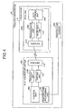
- Fig. 4 is a functional block diagram of a system structure of a temperature monitoring system according to a second embodiment of the present invention;
- Fig. 5 is a functional block diagram of a system structure of a temperature monitoring system according to a third embodiment of the present invention;
- Fig. 6 is a functional block diagram of a system structure of a temperature monitoring system according to a fourth embodiment of the present invention;
- Fig. 7 is a functional block diagram of a system structure of a temperature monitoring system according to a fifth embodiment of the present invention;
- Fig. 8 is a functional block diagram of a system structure of a temperature monitoring system according to a sixth embodiment of the present invention;
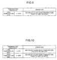
- Fig. 9 is a diagram of an example of a temperature threshold stored by an RFID tag;
- Fig. 10 is a diagram of an example in which an RFID tag stores two temperature thresholds;
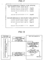
- Fig. 11 is a diagram of an example of setting of group addresses;
- Fig. 12 is a flow diagram of a flow of emergency response command processing;
- Fig. 13 is an explanatory diagram for explaining an on-vehicle vibration monitoring system according to an eighth embodiment of the present invention;
- Fig. 14 is a diagram of examples of means of transportation and routes;
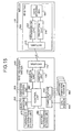
- Fig. 15 is a functional block diagram of a system structure of the on-vehicle vibration monitoring system according to the eighth embodiment;
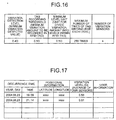
- Fig. 16 is a diagram of an example of threshold information stored by a threshold information storing unit;
- Fig. 17 is a diagram of an example of history information stored by a history information storing unit;
- Fig. 18 is a diagram of an example of vibration information stored by a data storing unit;
- Fig. 19 is a flowchart of a processing procedure of processing for recording vibration information in an RFID tag by a vibration recording unit; and
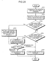
- Fig. 20 is a flowchart of a processing procedure of quality judgment processing by a quality judging unit.
- Exemplary embodiments of a radio IC tag reader writer, a radio IC tag system, and a radio IC tag data writing method embodying the present invention will be hereinafter explained in detail with reference to the attached drawings.
- Fig. 1 is a functional block diagram of a structure of a temperature monitoring system according to a first embodiment of the present invention. The temperature monitoring system includes an RFID
tag reader writer 100, afreezing warehouse 20 in whichfresh food 10, like tuna fish, is stored, and anRFID tag 200 that is attached to thefresh food 10 and that monitors temperature of thefresh food 10. Although only one piece offresh food 10 and oneRFID tag 200 are shown in Fig. 1, there may be many different items of fresh foods each attached with an RFID tag. - The RFID
tag reader writer 100 is an apparatus that reads out data from theRFID tag 200 and writes data in theRFID tag 200 using radio. The RFIDtag reader writer 100 includes anantenna 110, areadout unit 120, awriting unit 130, atemperature processing unit 140, atemperature sensor 150, and acontrol unit 160. - The
antenna 110 is a processing unit that transmits and receives data to and from theRFID tag 200 by radio based on a data readout request from thereadout unit 120 and a data writing request from thewriting unit 130. - The
readout unit 120 is a processing unit that transmits a data readout request to theRFID tag 200 and receives requested data from theRFID tag 200. More specifically, thereadout unit 120 requests readout of data designating a tag address for identifying theRFID tag 200, a storage address for data, and a data length. - The
writing unit 130 is a processing unit that transmits a data writing request to theRFID tag 200 together with data to be written. More specifically, thewriting unit 130 requests writing of data designating a tag address, a storage address of data, and data length. - The
temperature processing unit 140 is a processing unit that periodically measures temperature in thefreezing warehouse 20 using thetemperature sensor 150 and instructs thewriting unit 130 to write the measured temperature in theRFID tag 200 together with measurement time. - This
temperature processing unit 140 periodically measures temperature in thefreezing warehouse 20 using thetemperature sensor 150 and instructs thewriting unit 130 to write the measured temperature in theRFID tag 200. This makes it possible to record and manage at what temperature thefresh food 10 is stored. - The
temperature sensor 150 is a sensor incorporated in the RFIDtag reader writer 100 and measures temperature in the freezing warehouse, in which the RFIDtag reader writer 100 is set, based on an instruction from thetemperature processing unit 140. - The
control unit 160 is a processing unit that controls the entire RFIDtag reader writer 100. More specifically, thecontrol unit 160 performs exchange and the like of data among the respective functional units to thereby cause the RFIDtag reader writer 100 to function as one apparatus. - The
RFID tag 200 is a radio IC tag, which stores information on thefresh food 10 to which theRFID tag 200 is attached, and includes anantenna 210, a transmittingunit 220, areceiving unit 230, and adata storing unit 240. - The
antenna 210 is a processing unit that transmits and receives data to and from the RFIDtag reader writer 100 by radio. Theantenna 210 receives transmitted data from the transmittingunit 220 and delivers received data to the receivingunit 230. - The transmitting
unit 220 is a processing unit that transmits data stored in thedata storing unit 240 to the RFIDtag reader writer 100 via theantenna 210 in response to a data readout request from the RFIDtag reader writer 100. - The receiving
unit 230 is a processing unit that writes data, which is received from the RFIDtag reader writer 100 via theantenna 210, in thedata storing unit 240 in response to a data writing request from the RFIDtag reader writer 100. - The
data storing unit 240 is for storing information concerning thefresh food 10. Fig. 2 is a diagram of an example of a data structure of thedata storing unit 240. As shown in the figure, in thisdata storing unit 240, a tag address (UID) for identifying theRFID tag 200, manufacturing time information indicating manufacturing time of thefresh food 10, manufacturing place information indicating a manufacturing place of thefresh food 10, storing place information indicating a storing place of thefresh food 10, warehousing information indicating warehousing time when thefresh food 10 is warehoused in a freezing warehouse, a present number of pieces of temperature information i indicating the number of pieces of temperature information stored at present, and i pieces of temperature information are stored together with measurement time information. Note that thisdata storing unit 240 can store n (≥i) pieces of temperature information together with the measurement time information. - Next, a processing procedure of temperature writing processing by the RFID
tag reader writer 100 according to the first embodiment will be explained. Fig. 3 is a flowchart of the processing procedure of the temperature writing processing by the RFIDtag reader writer 100 according to the first embodiment. - Note that, here, it is assumed that the RFID
tag reader writer 100 knows a tag address of theRFID tag 200 and addresses, where the respective pieces of information in thedata storing unit 240 shown in Fig. 2 are stored, in advance. - As shown in Fig. 3, in this RFID
tag reader writer 100, thetemperature processing unit 140 inputs temperature from thetemperature sensor 150 at a fixed time interval (step S101). Then, designating a tag address, thetemperature processing unit 140 reads out the present number of pieces of temperature information from theRFID tag 200 using the readout unit 120 (step S102) and calculates the next temperature information storing address from a temperature information storing starting address and the present number of pieces of temperature information (step S103). - Then, the
temperature processing unit 140 writes the inputted temperature in the next temperature information storing address of theRFID tag 200 together with measurement time using the writing unit 130 (step S104) and adds "1" to the present number of pieces of temperature information and writes the present number of pieces of temperature information in the RFID tag 200 (step S105). - In this way, the
temperature processing unit 140 inputs temperature from thetemperature sensor 150 at the fixed time interval and writes the inputted temperature in theRFID tag 200 together with the measurement time. This makes it possible to manage a temperature history of thefresh food 10 in the freezingwarehouse 20. - As described above, in the first embodiment, the
temperature processing unit 140 of the RFIDtag reader writer 100 measures temperature at the fixed time interval using thetemperature sensor 150 and writes measured temperature in theRFID tag 200. This makes it possible to manage storing temperature of thefresh food 10 in the freezingwarehouse 200 using theRFID tag 200. - Incidentally, in the first embodiment, the case in which the RFID
tag reader writer 100 has thetemperature sensor 150 incorporated therein is explained. However, it is also possible to use a temperature sensor by connecting the temperature sensor to an RFID tag reader writer that does not have a temperature sensor incorporated therein. Thus, in a second embodiment of the present invention, a temperature monitoring system, which connects a temperature sensor to an RFID tag reader writer to perform temperature monitoring of fresh food stored in a freezing warehouse, will be explained. - Fig. 4 is a functional block diagram of a system structure of the temperature monitoring system according to the second embodiment. Note that, here, for convenience of explanation, functional units carrying out the same roles as the respective units shown in Fig. 1 will be denoted by the identical reference numerals, and a detailed explanation of the functional units will be omitted.
- As shown in Fig. 4, in this temperature monitoring system, an RFID
tag reader writer 400 is used instead of the RFIDtag reader writer 100, and the RFIDtag reader writer 400 measures temperature using atemperature sensor 450, which is set near fresh food, instead of having thetemperature sensor 150 incorporated therein. - A
temperature processing unit 440 measures temperature near thefresh food 10 at a fixed time interval using thetemperature sensor 450 and writes a measured value in theRFID tag 200 together with measurement time using thewriting unit 130. - As described above, in the second embodiment, the
temperature sensor 450 is arranged near thefresh food 10, and thetemperature processing unit 440 measures temperature in the freezingwarehouse 20 using thetemperature sensor 450. This makes it possible to measure temperature of thefresh food 10 accurately. - In the first and the second embodiments, the case in which the RFID tag reader writer measures temperature in the freezing warehouse independently using the temperature sensor and writes the measured temperature in the
RFID tag 200 is explained. However, the RFID tag reader writer can also transfer measured temperature to a host computer and write the temperature in theRFID tag 200 according to an instruction from the host computer. Thus, in a third embodiment of the present invention, a temperature monitoring system, which transfers measured temperature to a host computer and writes the temperature in theRFID tag 200 according to an instruction from the host computer, will be explained. - Fig. 5 is a functional block diagram of a system structure of the temperature monitoring system according to the third embodiment. Note that, here, for convenience of explanation, functional units carrying out the same roles as the respective units shown in Fig. 4 will be denoted by the identical reference numerals, and a detailed explanation of the functional units will be omitted. As shown in Fig. 5, this temperature monitoring system includes an RFID
tag reader writer 500, theRFID tag 200, and ahost PC 300. - The
host PC 300 is a computer that receives temperature measured by the RFIDtag reader writer 500 and instructs the RFIDtag reader writer 500 to write the temperature in theRFID tag 200. Thehost PC 300 is connected to the RFID tag reader writer by a network. - The RFID
tag reader writer 500 includes acommunication unit 570 in addition to theantenna 110, thereadout unit 120, thewriting unit 130, thetemperature processing unit 440, and acontrol unit 560 that controls the entire RFIDtag reader writer 500. Thecommunication unit 570 communicates with thehost PC 300 via the network. Thecommunication unit 570 receives data to be written in theRFID tag 200 from thehost PC 300 and transmits temperature or the like measured by thetemperature processing unit 440 to thehost PC 300. - As described above, in the third embodiment, the RFID
tag reader writer 500 transmits measured temperature to thehost PC 300, and thehost PC 300 instructs the RFIDtag reader writer 500 to write the temperature in theRFID tag 200. Thus, thehost PC 300 can also write necessary data in theRFID tag 200 in addition to the temperature. - In the first to the third embodiments, the case in which temperature measured by an RFID tag reader writer is recorded in the
RFID tag 200 is explained. However, it is also possible to manage the temperature measured by the RFID tag reader writer in a host PC. Thus, in a fourth embodiment of the present invention, a temperature monitoring system, which transfers temperature measured by an RFID tag reader writer to a host PC and manages the temperature in the host PC, will be explained. - Fig. 6 is a functional block diagram of a system structure of the temperature monitoring system according to the fourth embodiment. Note that, here, for convenience of explanation, functional units carrying out the same roles as the respective units shown in Fig. 5 will be denoted by the identical reference numerals, and a detailed explanation of the functional units will be omitted. As shown in Fig. 6, this temperature monitoring system includes the RFID
tag reader writer 500, anRFID tag 600, and a host PC 310. - The host PC 310 is a computer that receives temperature measured by the RFID
tag reader writer 500 and instructs the RFIDtag reader writer 500 to write the temperature in an RFID tag. However, unlike thehost PC 300, the host PC 310 includes adata storing unit 311. - The
data storing unit 311 is for storing temperature measured by the RFIDtag reader writer 500. Thedata storing unit 311 stores temperature of thefresh food 10 using the same data structure as thedata storing unit 240 shown in Fig. 2. - On the other hand, a
data storing unit 640 of theRFID tag 600 does not store temperature information unlike thedata storing unit 240. - As described above, in the fourth embodiment, temperature information is managed using the host PC 310 instead of an RFID tag. This makes it possible to manage more information on the fresh food in addition to temperature information during storage of the fresh food in the freezing
warehouse 20. For example, a GPS sensor is connected to an RFID tag reader writer to manage information on the GPS sensor in the host PC 310, whereby it is possible to manage a moving place and temperature of fresh food in association with each other. - In the first to the fourth embodiments, the temperature monitoring system using one RFID tag reader writer is explained. However, for example, when a freezing warehouse is large, plural RFID tag reader writers may be used. Thus, in a fifth embodiment of the present invention, a temperature monitoring system using two RFID tag reader writers will be explained.
- Fig. 7 is a functional block diagram of a system structure of the temperature monitoring system according to the fifth embodiment. As shown in the figure, this temperature monitoring system is constituted by connecting two RFID
tag reader writers host PC 320 via a LAN. Here, the RFIDtag reader writer 700 has a temperature sensor incorporated therein, and the RFIDtag reader writer 710 does not have a temperature sensor incorporated therein. - The RFID
tag reader writer 700 transfers measured temperature to thehost PC 320. Thehost PC 320 instructs the RFIDtag reader writer 700 to write the temperature received from the RFIDtag reader writer 700 in theRFID tag 200 managed by the RFIDtag reader writer 700 and also instructs the RFIDtag reader writer 710 to write the temperature in theRFID tag 200 managed by the RFIDtag reader writer 710. - As described above, in the fifth embodiment, the RFID
tag reader writer 700 having the temperature sensor incorporated therein transfers measured temperature to thehost PC 320, and thehost PC 320 instructs the RFIDtag reader writers RFID tag 200. This makes it possible to perform temperature monitoring for a large number of items of fresh food stored in a large freezing warehouse using one RFID tag reader writer having a temperature sensor incorporated therein. - Note that, here, since the
host PC 320 instructs the RFIDtag reader writers RFID tag 200, it is possible to process temperature information in thehost PC 320 and write the temperature information in theRFID tag 200. In addition, when only temperature information is written in theRFID tag 200, the RFIDtag reader writer 700 can also transmit the temperature information directly to the RFIDtag reader writer 710 without the intervention of thehost PC 320. - In the fifth embodiment, the case in which one RFID tag reader writer has a temperature sensor incorporated therein is explained. However, it is also possible to establish a temperature monitoring system by combining an RFID tag reader writer having a temperature sensor with high accuracy incorporated therein and an RFID tag reader writer having a temperature sensor with lower accuracy incorporated therein. Thus, in a sixth embodiment of the present invention, a temperature monitoring system, in which an RFID tag reader writer having a temperature sensor with high accuracy incorporated therein and an RFID tag reader writer having a temperature sensor with lower accuracy incorporated therein are combined, will be explained.
- Fig. 8 is a block diagram of a system structure of the temperature monitoring system according to the sixth embodiment. As shown in the figure, this temperature monitoring system is constituted by connecting an RFID
tag reader writer 711, which has a temperature sensor with high accuracy incorporated therein as a master sensor, and plural RFIDtag reader writers 712, which has temperature sensors with lower accuracy incorporated therein, via a LAN. - The RFID
tag reader writers 712 receive a value measured by the master sensor from ahost PC 330 at the time of system startup or the like and compare the measured value with values measured by the sensors incorporated therein to calculate a correction value. Then, the RFIDtag reader writers 712 store the calculated correction value and correct the values measured by the sensors incorporated therein to record the values in the RFID tags 200. - As described above, in the sixth embodiment, a measured value of the temperature sensor with high accuracy is used to correct measured values of the other temperature sensors and record the corrected measured values in the
RFID tag 200. This makes it possible to eliminate an influence due to fluctuation in accuracy and errors of temperature sensors and record temperature information with high accuracy in the RFID tags 200. - Note that, in the sixth embodiment, the temperature sensor with high accuracy is used as a master sensor. However, it is also possible to use sensors with the same accuracy as all the temperature sensors, transfer temperature measured by each RFID tag reader writer to a host PC, calculate an average of measured values of all the sensors in the host PC, and write the average in each RFID tag.
- In addition, each RFID tag reader writer can compare the average calculated in the host PC and the measured value of each sensor to calculate a correction value and correct the measured value of each sensor with the correction value to write the corrected measured value in an RFID tag. In this way, it is possible to make it unnecessary to calculate an average in every measurement by using a correction value.
- In the first to the sixth embodiment, the case in which temperature is measured at the fixed time interval and recorded together with measurement time is explained. However, it is also possible to store a threshold for temperature in an RFID tag and, only when temperature of the
fresh food 10 exceeds the threshold, record the temperature in the RFID tag. - Fig. 9 is a diagram of an example of a temperature threshold that is stored by the RFID tag. The diagram indicates that the threshold is set to 25°C and, when temperature rises to 26°C or more, the temperature is written in the RFID tag as an alarm.
- In other words, a threshold temperature is set in an RFID tag in advance as a threshold value (alarm judgment value) of a temperature sensor in an RFID tag reader writer (or set in a file of a host PC as a threshold associated with a tag address).
- Then, when an operation starts, the RFID tag reader writer reads the threshold temperature from the RFID tag first (or every time comparison is performed) and compares the threshold temperature with a value of the sensor at every designated time. As a result of the comparison, when the value exceeds the threshold temperature, the RFID tag reader writer writes the result in the RFID tag.
- In this way, when temperature exceeds the threshold temperature, the temperature is written in the RFID tag, whereby it is possible to confirm later whether fresh food has been kept in a predetermined temperature environment or has been out of the predetermined temperature environment using a record written in the RFID tag.
- Note that a result of comparison with the threshold temperature may be notified to the host PC every time the comparison is performed, or the host PC may be caused to immediately recognize occurrence of abnormality in fresh food attached with the RFID tag. In addition, the threshold temperature stored in the RFID tag may be stored on the sensor side.
- In some cases, it is necessary to set temperature thresholds not only on a high temperature side but also on a low temperature side. Fig. 10 is a diagram of an example in which an RFID tag stores two temperature thresholds. The figure indicates a case in which -5°C is set as a threshold temperature on the low temperature side.
- In addition, it is also possible to set the same value or different values for plural and different kinds of sensors as threshold values. For example, since ranges of temperature that measuring objects can withstand are different, it is likely that temperature desired to be monitored varies or it is likely that monitored temperature varies due to a difference of a packing state (inside and outside of a box). Therefore, when the measuring objects are stored in one room, naturally, it is necessary to set different values for the sensors.
- In order to realize this, plural thresholds are stored in each RFID tag (or in a file of a host PC as thresholds associated with tag addresses), and this setting is performed in advance for each monitoring object.
- Then, when an operation starts, the RFID tag reader writer reads the threshold from the RFID tag first (or every time comparison is performed) and compares the threshold with a value of the corresponding sensor at every designated time. As a result of the comparison, when the value exceeds the threshold, the RFID tag reader writer writes the result in the RFID tag.
- It is needless to mention that the threshold (defined temperature) stored in the RFID tag may be stored on the sensor side, the RFID tag reader writer side, or the host PC side as long as the threshold is common to the respective RFID tags (monitoring objects).
- In addition to the threshold, it is also possible to set a check condition for comparing a measured value with the threshold to check the measured value. For example, a check condition for checking measured values in Wednesday every week or checking measured values from 9 a.m. to 8 p.m. every day can be set.
- Although only the temperature sensor is explained in this embodiment, when monitoring is performed by sensors including other sensors (e.g., a humidity sensor), monitoring can be performed under both the conditions. In addition, if a monitoring object flag is provided in an RFID tag, it is possible to designate a monitoring sensor that should be required on each monitoring object side among different kinds of plural sensors. In this way, it is also possible to designate different kinds of plural sensor conditions and monitor fresh food.
- Incidentally, it may be desired to raise processing priorities for part of plural managing objects attached with RFID tags. For example, when plural kinds of food having different freshness dates are monitored collectively depending on temperature, there is a case in which it is desired to process the kinds having different freshness dates as separate groups (change of the freshness dates, management of shipment dates, etc.) from a point when the temperature reaches certain temperature.
- In such a case, if tag addresses of all the RFID tags can be managed in advance, there is a method of creating association of the tag addresses with the groups for each freshness date in advance, designating respective addresses, and processing the managing objects. However, when food is distributed through plural warehouses and process lines from producing districts, all tag addresses cannot be managed in advance in many cases.
- When tag addresses of all products cannot be managed in advance in this way, since processing for each RFID tag is performed while presence of all RFID tags is recognized using an all-UID recognition command (anti-collision command), there is a disadvantage that processing priorities for part of the RFID tags cannot be raised.
- As a measure for avoiding this disadvantage, there is also a method of reading tag addresses of all RFID tags, preparing a correspondence table of the respective addresses and product life-cycles in the outside, and performing priority processing with the respective tag addresses designated in a pre-stage process. However, there is a problem in that, for example, prior address reading work is required.
- To avoid this problem, in a seventh embodiment of the present invention, processing priorities for part of the managing objects are raised by the following two methods.
- (1) Method of realization through address grouping
- (2) Method of processing through threshold setting and dedicated commands Both the methods will be hereinafter explained.
- This method uses group select commands to thereby group plural kinds of food having different freshness dates depending on temperature and execute different kinds of processing for the food. More specifically, it is assumed that the plural kinds of food are grouped as indicated below, and processing for the respective groups is performed.
- Group A: When temperature reaches 25°C, it is necessary to reduce a freshness date by three days
- Group B: When temperature reaches 30°C, it is necessary to reduce a freshness date by three days (general products)
- In this example, when temperature in a warehouse under temperature control rises to, for example, 25°C, only freshness dates of products in the group A are reduced by three days to perform shipment management after that. Specific addressing and the like will be hereinafter explained.
- Sub-addresses corresponding to the groups A and B are allocated to user areas in RFID tags. These sub-addresses have an object of facilitating groping of the respective RFID tags. This is because, although UID addresses of 64 bits may be used without change usually, since corresponding relations of the UIDs and the groups A and B are not consistent usually, it is difficult to distinguish grouping to be described later according to a bit if the UIDs are used without change.
- As identification for setting a group address to a group level with a high processing priority (group A in this example), a
bit 4 of an address prepared in a user area is defined as a group identification bit. A group address is set as shown in Fig. 11 with anaddress bit 4 set to "1" with respect to an RFID tag of the group A requiring a high processing level. - Then, as shown in Fig. 11, in a state in which a sub-address for each group is set as shown in Fig. 11, when temperature rises to 25°C outside the defined temperature, filter information with the
bit 4 set to "1" is added to issue a group select command. - Consequently, only the group A with the
sub-address bit 4 set to "1" comes into a selected state (ID state) to be capable of responding to commands after that. Since the group B is in a Ready state (sleep state), the group B does not respond to commands. - In this state, processing with respect to the group A is made possible, and reading or writing with respect to individual RFID tags in the group A or writing with respect to all the RFID tags (multi-write) is made possible. Thus, it is possible to change freshness date information and priorities for shipment processing concerning the respective RFID tags (products).
- When this processing ends, it is also possible to return the group A to the same state as the group B with an unselect command. Tag groups are limited to a fixed range temporarily to process the tag groups in this way, whereby it is possible to improve processing efficiency.
- Temperature thresholds, at which an alarm should be given, are set for each tag group with respect to the respective RFID tags (products).
-
- Group A: When temperature reaches 25°C, it is necessary to reduce a freshness date by three days → Threshold 25°C
- Group B: When temperature reaches 30°C, it is necessary to reduce a freshness date by three days →
Threshold 30°C - Then, as shown in Fig. 12, an RFID tag reader writer side prepares an emergency response command (Read-em) as a dedicated command with respect to an RFID tag and issues a main command added with present temperature information to the RFID tag side at a fixed interval.
- When the main command is received on the RFID tag side, the RFID tag side compares present temperature information added to the main command and a temperature threshold set in advance and returns a response (including a tag address of the RFID tag) only when the present temperature information exceeds the temperature threshold. Consequently, since only tags recognizing the response as a temperature alarm respond, it is possible to perform processing in shorter time than recognizing and confirming all tags individually.
- As described above, in the seventh embodiment, since it is made possible to process only part of RFID tags using a group address or a dedicated command, the part of RFID tags can be processed preferentially.
- In the first to the seventh embodiments, the temperature monitoring system for fresh food is explained. However, it is also possible to establish other applied systems by incorporating other sensors in or connecting other sensors to an RFID tag reader writer. Thus, in an eighth embodiment of the present invention, an on-vehicle vibration monitoring system, which uses an RFID tag reader writer to which a GP sensor and a vibration sensor are connected, will be explained.
- First, the on-vehicle vibration monitoring system according to the eighth embodiment will be explained. Fig. 13 is an explanatory diagram for explaining the on-vehicle vibration monitoring system according to the eighth embodiment. This on-vehicle vibration monitoring system is a system that, when melons are transported from a place of origin (e.g., Yubari in Hokkaido) to a center (e.g., Tokyo), monitors vibration during the transportation.
- High-grade melons lose a commercial value thereof when a quality of melon declines due to damage caused by vibration, shock, or the like or due to vibration of a fixed amount (fixed number of times) or more that is not so serious as to cause damage. Although the products (melons) are boxed and simply packed, vibration or shock of a fixed amount (strength and number of times) or more applied to the products makes guarantee by the simple packing doubtful.
- In addition, to deliver one product to a destination, as shown in Fig. 14, plural means of transportation are used, although there is only one route. In addition, since the product is transported via plural dealers, it is difficult to manage vibration applied to the product.
- In the eighth embodiment, a case in which simply-packed products (melons) are loaded on a vehicle-mounted container in a large quantity and transported is assumed. It is assumed that the products are delivered to the destination through plural means shown in Fig. 14. In addition, as an example of quality control during transportation, it is assumed that product confirmation (confirmation of presence or absence of damage) for each product is required when vibration of 1 G or more is applied, and tasting confirmation is required when the number of times of vibration of 0.5G or more exceeds 100 times.
- As shown in Fig. 13,
vibration sensors 850 are arranged in four places in the vehicle-mounted container to grasp vibration/shock information, and an RFID tag reader writer including a sensor and a GPS monitoring function is arranged outside the vehicle-mounted container (or may be arranged inside the container excluding a GPS antenna). - Only one
vibration sensor 850 may be arranged if thevibration sensor 850 is stable in the vehicle-mounted container. However, since there is slight fluctuation depending on a position, thevibration sensors 850 are arranged in the four places, and an average of the fourvibration sensors 850 is adopted as a vibration amount. - In addition, an
RFID tag 900 is attached to each product by a unit of box in which plural melons are packed collectively (e.g., sixteen in number). - Next, a system structure of the on-vehicle vibration monitoring system according to the eighth embodiment will be explained. Fig. 15 is a functional block diagram of a structure of the on-vehicle vibration monitoring system according to the eighth embodiment. Note that, here, for convenience of explanation, functional units carrying out the same roles as the respective units shown in Fig. 1 will be denoted by the identical reference numerals, and a detailed explanation of the functional units will be omitted.
- As shown in Fig. 15, this on-vehicle vibration monitoring system includes an RFID
tag reader writer 800 and theRFID tag 900 attached to amelon 30 and monitors a vibration amount of themelon 30 transported by a vehicle-mounted container. Note that, here, for convenience of explanation, only onemelon 30 and only oneRFID tag 900 are shown, this vibration monitoring system monitors vibration amounts of melons in plural boxes attached with RFID tags. - The RFID
tag reader writer 800 includes theantenna 110, thereadout unit 120, thewriting unit 130, avibration recording unit 820, aquality judging unit 830, acommunication port 840, acontrol unit 860, a thresholdinformation storing unit 870, and a historyinformation storing unit 880. - The
vibration recording unit 820 records information on the vibration in the historyinformation storing unit 880 and theRFID tag 900 if vibration equal to or larger than a threshold occurs while themelon 30 is transported. - The
quality judging unit 830 is a processing unit that, when the transportation of themelon 30 ends, reads out the vibration information recorded in theRFID tag 900 and judges a quality of themelon 30 based on the read-out vibration information. - The
communication port 840 is an interface for making connection with various sensors to input measured values. Here, positional information is inputted from aGPS sensor 855 and vibration amounts are inputted from the fourvibration sensors 850. - The
control unit 860 is a processing unit that controls the entire RFIDtag reader writer 800. More specifically, thecontrol unit 860 performs exchange and the like of data among the respective functional units to thereby cause the RFIDtag reader writer 800 to function as one apparatus. - The threshold
information storing unit 870 is a storing unit that stores a threshold of processing with respect to vibration amounts inputted from thevibration sensor 850. Fig. 16 is a diagram of an example of threshold information stored by the thresholdinformation storing unit 870. - As shown in the figure, the threshold information stored by this threshold
information storing unit 870 includes a vibration detection level, a tag recording threshold, a minimum level unit, a maximum number of times of tag writing, and the number of vibration sensors. - Here, the vibration detection level is a vibration amount of a minimum level that the RFID
tag reader writer 800 should process, the tag recording threshold is a vibration amount of a minimum level that the RFIDtag reader writer 800 should record in theRFID tag 900, and the minimum level unit is a level unit (width) of a vibration amount that should be recorded on theRFID tag 900 side. - The maximum number of times of tag writing is a maximum value that can be counted on the
RFID tag 900 side, and the number of vibration sensors is the number of sensors arranged in the vehicle-mounted container. Here, the number of vibration sensors is four. As a vibration amount, an average of information from the four sensors is calculated, whereby an influence of partial vibration is eliminated. - The history
information storing unit 880 is a storing unit that, when vibration equal to or larger than the threshold stored in the thresholdinformation storing unit 870 occurs, stores information on the vibration. Fig. 17 is a diagram of an example of history information stored by the historyinformation storing unit 880. - As shown in the figure, the history information stored by this history
information storing unit 880 includes occurrence time indicating time when vibration equal to or larger than the vibration detection level occurs, positional information indicating a position where the vibration occurs, a vibration level of the vibration, and user information in which arbitrary information like a route name and a product name can be written. - The
RFID tag 900 is a radio IC tag that stores information on vibration of themelon 30 in the data storing unit 940. Fig. 18 is a diagram of an example of vibration information stored by the data storing unit 940. As shown in the figure, numbers of times of occurrence are stored in this data storing unit 940 with respect to four vibration levels. - Next, a processing procedure of processing for recording vibration information in the
RFID tag 900 by thevibration recording unit 820 will be explained. Fig. 19 is a flowchart of the processing procedure of the processing for recording vibration information in theRFID tag 900 by thevibration recording unit 820. Note that, here, it is assumed that a tag address of theRFID tag 900 is known in advance. - As shown in the figure, this
vibration recording unit 820 inputs measured values of the four vibration sensors from thecommunication port 840 and calculates an average. Then, when vibration designated in threshold information occurs (step S201), thevibration recording unit 820 designates a tag address and issues a Read command using the readout unit 120 (step S202), and reads out the number of times of occurrence of a vibration level corresponding to the vibration. - Then, the
vibration recording unit 820 adds "1" to the read-out number of times of occurrence (step S203), issues a Write command using thewriting unit 130, and writes the updated number of times of occurrence in the RFID tag 900 (step S204). - In this way, when vibration designated in the threshold information occurs, this
vibration recording unit 820 can record a vibration occurrence state during transportation by updating the number of times of occurrence stored in theRFID tag 900 by "1". - Next, a processing procedure of quality judgment processing by the
quality judging unit 830 will be explained. Fig. 20 is a flowchart of the processing procedure of the quality judgment processing by thequality judging unit 830. Note that this quality judgment processing is performed when themelon 30 arrives at a destination. - As shown in the figure, this
quality judging unit 830 issues a Read command using thereadout unit 120 designating a tag address (step S301) and reads out storage areas (numbers of times of occurrence) of all the vibration levels from the RFID tag 900 (step S302). - Then, the
quality judging unit 830 judges whether vibration equal to or larger than 0.5G has occurred one-hundred times or more based on the read-out number of times (step S303). If the vibration equal to or larger than 0.5G has occurred one-hundred times or more, thequality judging unit 830 instructs an inspector to perform appearance audit and tasting inspection with respect themelon 30 attached with the RFID tag 900 (step S304). - On the other hand, if the vibration equal to or larger than 0.5G has not occurred one-hundred times or more, the
quality judging unit 830 judges whether vibration equal to or larger than 1 G has occurred at least once (step S305). If the vibration equal to or larger than 1G has occurred at least once, thequality judging unit 830 instructs the inspector to perform appearance audit with respect to themelon 30 attached with the RFID tag 900 (step S306). If the vibration equal to or larger than 1 G has not occurred at least once, thequality judging unit 830 judges that themelon 30 attached with theRFID tag 900 is a non-defective product (step S307). - When the
quality judging unit 830 has instructed the appearance audit or the tasting inspection, thequality judging unit 830 causes the inspector to input an audit result to judge whether themelon 30 is a non-defective product (step S308). If the audit result indicates a non-defective product, thequality judging unit 830 judges that all themelons 30 attached with theRFID tag 900 are non-defective products (step S307). If the audit result indicates a defective product, thequality judging unit 830 judges that all themelons 30 attached with theRFID tag 900 are defective products (step S309). - In this way, this
quality judging unit 830 reads out numbers of times of occurrence of all the vibration levels from theRFID tag 900 and judges a quality of themelon 30 based on the numbers of times of occurrence, whereby it is possible to perform sure quality confirmation. - In addition, detailed information on transportation channels according to the
GPS sensor 855 and vibration information are recorded in association with each other with respect to all the transportation channels. This makes it also possible to judge a quality for each of the transportation channels. For example, when a truck service is used, it is possible to manage time of loading on and unloading from the truck, a general road and an expressway, and statistic information for each carrier and to take a quality measure for the next time accurately. - As described above, in the eighth embodiment, the
vibration recording unit 820 records information on vibration, which occurs during transportation, in theRFID tag 900, and thequality judging unit 830 judges a quality of themelon 30 based on the vibration information recorded in theRFID tag 900. This makes it possible to manage the quality of themelon 30 surely. - In the first to the eighth embodiments, the cases in which the temperature sensor, the GPS sensor, and the vibration sensor are used as sensors are explained. However, the present invention is not limited to this case and can also be applied to, for example, cases in which other sensors like a humidity sensor, an acceleration sensor, a shock sensor, a water quality sensor, and an ion sensor are used.
- In addition, in the first to the eighth embodiments, the case in which the RFID tag is used is explained. However, the present invention is not limited to this case and can also be applied to, for example, cases in which other media having a storing property like an IC card and a memory card are used.
- According to an embodiment of the present invention, since data concerning an environment, in which a product attached with a radio IC tag is placed, is collected on a real time basis, there is an effect that it is possible to manage the product surely based on the collected data.
- Although the invention has been described with respect to a specific embodiment for a complete and clear disclosure, the appended claims are not to be thus limited but are to be construed as embodying all modifications and alternative constructions that may occur to one skilled in the art which fairly fall within the basic teaching herein set forth.
Claims (19)
- A radio IC tag reader writer that reads out data from a radio IC tag and writes data in the radio IC tag using radio, comprising:a receiving unit that receives from a sensor a value of a parameter measured by the sensor; anda writing unit that writes the value in the radio IC tag.
- The radio IC tag reader writer according to claim 1, wherein the sensor is incorporated in the radio IC tag reader writer.
- The radio IC tag reader writer according to claim 1 or 2, wherein
the receiving unit receives the value for a plurality of times at a predetermined first time interval, and
the writing unit writes the value in the radio IC tag for a plurality of times at a predetermined second time interval. - The radio IC tag reader writer according to claim 1 or 2, wherein
the receiving unit receives time of measurement of the parameter is measured by the sensor, and
the writing unit writes the time and the value in the radio IC tag in a corresponding manner. - The radio lC tag reader writer according to any preceding claim, further comprising a judging unit that judges whether the value received by the receiving unit exceeds a predetermined threshold, wherein
the writing unit writes the value in the radio IC tag if the judging unit judges that the value exceeds the predetermined threshold. - The radio IC tag reader writer according to claim 5, wherein the predetermined threshold is stored in the radio IC tag and the judging unit reads the predetermined threshold from the radio IC tag.
- The radio IC tag reader writer according to claim 6, wherein a threshold check condition is stored in the radio IC tag and the judging unit reads the threshold check condition and based on the threshold check condition judges whether the value exceeds the predetermined threshold.
- The radio IC tag reader writer according to claim 7, wherein the threshold check condition relates to time.
- The radio IC tag reader writer according to any preceding claim, further comprising a transmitting unit that transmits the value received by the receiving unit to a computer, wherein
the writing unit writes the value in the radio IC tag based on an instruction from the computer. - The radio IC tag reader writer according to claim 1, wherein the sensor is a temperature sensor.
- The radio IC tag reader writer according to claim 1, wherein the sensor is a GPS sensor and a vibration sensor.
- A radio IC tag system constituted by connecting at least one first radio IC tag reader writer with a plurality of second radio IC tag reader writers via a network, each of the first radio IC tag reader writer and the second radio IC tag reader writers having a corresponding radio IC tag, wherein
the first radio IC tag reader writer includes
a first receiving unit that receives from a sensor a value of a parameter measured by a sensor;
a first writing unit that writes the value in the corresponding radio IC tag; and
a transmitting unit that transmits the value received by the first receiving unit to the second radio IC tag reader writers via the network; and
each of the second radio IC tag reader writers includes
a second receiving unit that receives the value transmitted by the transmitting unit; and
a second writing unit that writes the value received by the second receiving unit in the corresponding radio IC tag. - The radio IC tag system according to claim 12, wherein
the transmitting unit transmits the value received by the first receiving unit to a computer connected to the network, and
the receiving unit receives the value from the computer. - A radio IC tag system constituted by connecting at least one first radio IC tag reader writer with a plurality of second radio IC tag reader writers via a network, each of the first radio IC tag reader writer and the second radio IC tag reader writers having a corresponding radio IC tag, wherein each of the first radio IC tag reader writer and the second radio IC tag reader writers includes
a receiving unit that receives from a corresponding sensor a value of a parameter measured by the corresponding sensor; and
a writing unit that writes the value in the corresponding radio IC tag, wherein
the sensor corresponding to the first radio IC tag reader writer has relatively higher sensitivity than the sensors corresponding to the second radio IC tag reader writers,
the first radio IC tag reader writer transmits the value to the second radio IC tag reader writers, and
the second radio IC tag reader writers calibrate the value they posses based on the value received from the first radio IC tag reader writer, and write the value after calibration in the corresponding radio IC tag. - A radio IC tag system that includes a plurality of radio IC tag reader writers connected to a computer via a network, each of the radio IC tag reader writers having a corresponding radio IC tag, wherein each of the radio IC tag reader writers includes
a first receiving unit that receives from a sensor a value of a parameter measured by the sensor;
a transmitting unit that transmits the value received by the first receiving unit to the computer via the network;
a second receiving unit that receives from the computer an average of values received by the computer from other radio IC tag reader writers; and
a writing unit that writes the average in the corresponding radio IC tag. - The radio IC tag system according to claim 15, further comprising a correcting unit that corrects the value received by the first receiving unit using the average received by the second receiving unit, wherein
the writing unit writes in the corresponding radio IC tag the value corrected by the correcting unit. - A method of writing data in a radio IC tag, comprising:receiving a value of a parameter measured by a sensor; andwriting the value in the radio IC tag.
- A temperature monitoring system that monitors temperature of a commodity, comprising:a radio IC tag reader writer, a radio IC tag attached to the commodity, and a temperature sensor that measures a temperature of the commodity or around the commodity, wherein the radio IC tag reader writer includesa receiving unit that receives from the temperature sensor a value that represents the temperature of the commodity; anda writing unit that writes the value in the radio IC tag.
- A vibration monitoring system that monitors vibrations of a commodity while the commodity is being transported, comprising:a radio IC tag reader writer, a radio IC tag attached to the commodity, and a vibration sensor that measures vibrations of the commodity or around the commodity, wherein the radio IC tag reader writer includesa receiving unit that receives from the vibration sensor a value that represents vibrations measured by the vibration sensor;a judging unit that judges whether the value received by the receiving unit exceeds a predetermined threshold; anda writing unit that writes the value in the radio IC tag if the judging unit judges that the value exceeds the predetermined threshold.
Applications Claiming Priority (1)
| Application Number | Priority Date | Filing Date | Title |
|---|---|---|---|
| JP2004201130A JP2006023963A (en) | 2004-07-07 | 2004-07-07 | Wireless IC tag reader / writer, wireless IC tag system, and wireless IC tag data writing method |
Publications (2)
| Publication Number | Publication Date |
|---|---|
| EP1615155A2 true EP1615155A2 (en) | 2006-01-11 |
| EP1615155A3 EP1615155A3 (en) | 2008-07-02 |
Family
ID=35058809
Family Applications (1)
| Application Number | Title | Priority Date | Filing Date |
|---|---|---|---|
| EP04257389A Withdrawn EP1615155A3 (en) | 2004-07-07 | 2004-11-29 | Radio IC tag system |
Country Status (6)
| Country | Link |
|---|---|
| US (1) | US7301439B2 (en) |
| EP (1) | EP1615155A3 (en) |
| JP (1) | JP2006023963A (en) |
| KR (1) | KR100678441B1 (en) |
| CN (2) | CN100390816C (en) |
| TW (1) | TW200602992A (en) |
Cited By (6)
| Publication number | Priority date | Publication date | Assignee | Title |
|---|---|---|---|---|
| WO2008067971A3 (en) * | 2006-12-05 | 2008-10-16 | Deutsche Post Ag | Container for sending objects and method for producing said container |
| EP2261834A1 (en) * | 2009-06-12 | 2010-12-15 | Hand Held Products, Inc. | Portable data terminal |
| EP2377067A4 (en) * | 2008-12-11 | 2012-06-27 | Intelleflex Corp | Inclusive or exclusive rfid tag interrogation and query round |
| DE102011103865A1 (en) * | 2011-06-09 | 2012-12-13 | Liebherr-Hausgeräte Lienz Gmbh | Cooling- and/or freezing apparatus, has detecting unit for detecting values of parameters e.g. temperature, and transmitting part for wirelessly transmitting stored values or data to receiver by wireless local area network and infrared |
| WO2013053011A1 (en) * | 2011-10-12 | 2013-04-18 | Bluechiip Limited | Storage cassette |
| EP2765535A4 (en) * | 2011-10-05 | 2015-06-10 | Korea Food Res Inst | SYSTEM FOR MONITORING THE QUALITY OF A PRODUCT IN REAL TIME |
Families Citing this family (83)
| Publication number | Priority date | Publication date | Assignee | Title |
|---|---|---|---|---|
| US7306489B2 (en) * | 2004-07-26 | 2007-12-11 | Fci Americas Technology, Inc. | Performance indicating electrical connector |
| US20060040546A1 (en) * | 2004-07-26 | 2006-02-23 | Fci Americas Technology, Inc. | Performance indicating electrical connector |
| US7545267B2 (en) * | 2004-09-17 | 2009-06-09 | Siemens Building Technologies, Inc. | Arrangement and method for product information interaction with building control system elements |
| WO2006086263A2 (en) * | 2005-02-08 | 2006-08-17 | Altivera L.L.C. | One point calibration integrated temperature sensor for wireless radio frequency applications |
| JP4484732B2 (en) * | 2005-03-02 | 2010-06-16 | 株式会社日立製作所 | Biological tissue transport apparatus and transport method |
| US8698604B2 (en) * | 2005-04-25 | 2014-04-15 | Lg Electronics Inc. | Reader control system |
| US7686232B2 (en) * | 2005-09-20 | 2010-03-30 | Novarus Corporation | System and method for food safety inspection |
| WO2007043585A1 (en) * | 2005-10-12 | 2007-04-19 | Brother Kogyo Kabushiki Kaisha | Tape processing device, tag label generation device, tag assembly, and tape processing method |
| KR100689367B1 (en) * | 2006-02-13 | 2007-03-02 | 삼성전자주식회사 | Method and system for improving information reading function from RDF tag |
| DE102006010291A1 (en) * | 2006-03-03 | 2007-09-06 | Jungheinrich Ag | Industrial truck with usage data acquisition |
| GB0605188D0 (en) * | 2006-03-16 | 2006-04-26 | Pte Ltd | Lifetime damage monitor |
| JP2007264799A (en) * | 2006-03-27 | 2007-10-11 | Nec Corp | Information management system, information management method, program and recording medium |
| JP4793638B2 (en) * | 2006-03-27 | 2011-10-12 | マツダ株式会社 | Pedestrian detection device for vehicles |
| KR100814152B1 (en) | 2006-06-12 | 2008-03-17 | 이성화 | Merchandise management method and management system therefor |
| JP2008003773A (en) * | 2006-06-21 | 2008-01-10 | Toyota Motor Corp | Wireless tag and ID reader |
| CN100559358C (en) * | 2006-08-15 | 2009-11-11 | 张卫钢 | Vibrating wire sensor electronic label management system |
| JP4235236B2 (en) * | 2006-09-12 | 2009-03-11 | 東芝テック株式会社 | Wireless communication device |
| JP4984774B2 (en) * | 2006-09-15 | 2012-07-25 | 富士通株式会社 | RF tag reader and retransmission control method |
| US12073272B2 (en) * | 2006-11-18 | 2024-08-27 | Rfmicron, Inc. | Generating a response by a radio frequency identification (RFID) tag within a field strength shell of interest |
| DE102006061815A1 (en) * | 2006-12-21 | 2008-06-26 | Endress + Hauser Conducta Gesellschaft für Mess- und Regeltechnik mbH + Co. KG | Retractable housing |
| US8087101B2 (en) * | 2007-01-19 | 2012-01-03 | James Riddell Ferguson | Impact shock absorbing material |
| US7696880B2 (en) * | 2007-02-07 | 2010-04-13 | International Business Machines Corporation | Hierarchical tagging of objects |
| US8040242B2 (en) * | 2007-02-07 | 2011-10-18 | International Business Machines Corporation | Hierarchical RFID |
| CN101246538A (en) * | 2007-02-14 | 2008-08-20 | 日电(中国)有限公司 | Radio frequency recognition system and method |
| JP5046374B2 (en) * | 2007-03-06 | 2012-10-10 | 中国電力株式会社 | Temperature abnormality diagnosis system |
| US8521993B2 (en) * | 2007-04-09 | 2013-08-27 | Intel Corporation | Providing thread fairness by biasing selection away from a stalling thread using a stall-cycle counter in a hyper-threaded microprocessor |
| US20080303669A1 (en) * | 2007-06-08 | 2008-12-11 | Symbol Technologies, Inc. | Vibration logging tag |
| JP4644871B2 (en) * | 2007-11-05 | 2011-03-09 | 独立行政法人 日本原子力研究開発機構 | Physical quantity measuring device and measuring method in airtight container |
| US8451119B1 (en) * | 2008-02-14 | 2013-05-28 | Impinj, Inc. | RFID reader system capable of adjusting tags to modify internal operations for a sensed environment |
| US9319756B2 (en) * | 2008-03-24 | 2016-04-19 | Intermec Ip Corp. | RFID tag communication triggered by sensed energy |
| US9035773B2 (en) * | 2008-03-27 | 2015-05-19 | Advanced Electronic Tracking | Environment monitoring and recording tag with remote sensing capability |
| JP5167961B2 (en) * | 2008-06-06 | 2013-03-21 | 富士通株式会社 | Information processing apparatus, program, and wireless transmission / reception circuit |
| US8002592B2 (en) | 2008-12-17 | 2011-08-23 | Hubbell Incorporated | Data collecting connection |
| SI22957A (en) * | 2009-01-07 | 2010-07-30 | Ids D.O.O. | Procedure for secure durable process registration within an active rfid label inside a labelled object |
| FI20095369A0 (en) * | 2009-04-03 | 2009-04-03 | Maricap Oy | Procedure and tools for waste management |
| CN101896023A (en) * | 2009-05-20 | 2010-11-24 | 扬光绿能股份有限公司 | Lighting device and control method thereof |
| JP5353481B2 (en) * | 2009-06-26 | 2013-11-27 | 富士通株式会社 | Article monitoring apparatus, article monitoring method, and computer program |
| US20110089591A1 (en) * | 2009-10-16 | 2011-04-21 | Gerber Scientific International, Inc. | Methods and Systems for Manufacturing Composite Parts |
| JP5471430B2 (en) * | 2009-12-25 | 2014-04-16 | 三菱電機株式会社 | Location management system |
| US10228001B2 (en) | 2010-09-22 | 2019-03-12 | Hubbell Incorporated | Transmission line measuring device and method for connectivity |
| US9697724B2 (en) | 2010-09-22 | 2017-07-04 | Hubbell Incorporated | Transmission line measuring device and method for connectivity and monitoring |
| CN103238161B (en) * | 2010-10-06 | 2016-06-15 | 韩国食品研究院 | Method and system for monitoring food quality |
| US20130285795A1 (en) * | 2010-10-22 | 2013-10-31 | Juhani Virtanen | Advanced functionality of remote-access devices |
| US9189661B1 (en) * | 2010-12-06 | 2015-11-17 | Globaltrak, Llc | Apparatus for establishing a mesh network for reefer sensor architecture |
| US9197984B2 (en) * | 2011-04-19 | 2015-11-24 | Qualcomm Incorporated | RFID device with wide area connectivity |
| CN102518905B (en) * | 2011-12-14 | 2013-07-31 | 合肥通用机械研究院 | Management system of blind plate with sensing unit and intelligent electronic tag |
| US20130162404A1 (en) * | 2011-12-27 | 2013-06-27 | Grant Edward Striemer | Apparatus and Method for Providing Product Information |
| TW201331736A (en) * | 2012-01-20 | 2013-08-01 | Askey Technology Jiangsu Ltd | Integrated temperature and humidity control device |
| CN102682317B (en) * | 2012-05-15 | 2016-03-30 | 中国科学院计算技术研究所 | A kind of intelligent electronic label infosystem and information interacting method thereof |
| CN102938114A (en) * | 2012-09-20 | 2013-02-20 | 华东理工大学 | Food safety tracking system in cold-chain logistics based on radio frequency identification device (RFID) and data validation method of system |
| TWI489093B (en) * | 2013-05-16 | 2015-06-21 | 國立成功大學 | Method for sensing multi-point temperatures applied to integrated circuit chips and system for the same |
| US9520057B2 (en) | 2013-06-19 | 2016-12-13 | Uchicago Argonne, Llc | Wireless remote monitoring of critical facilities |
| US10078811B2 (en) | 2013-11-29 | 2018-09-18 | Fedex Corporate Services, Inc. | Determining node location based on context data in a wireless node network |
| KR20160090374A (en) * | 2014-02-04 | 2016-07-29 | 아플릭스 아이피 홀딩스 가부시키가이샤 | Electronic device management system, electronic device management server, and electronic device management method |
| JP6287446B2 (en) * | 2014-03-26 | 2018-03-07 | 富士通株式会社 | Data processing apparatus and data processing apparatus control method |
| CN103955721B (en) * | 2014-04-11 | 2017-07-28 | 深圳市远望谷信息技术股份有限公司 | Use the method and device of electronic tag measuring environment temperature |
| US10453023B2 (en) | 2014-05-28 | 2019-10-22 | Fedex Corporate Services, Inc. | Methods and node apparatus for adaptive node communication within a wireless node network |
| MX2017008822A (en) | 2014-12-31 | 2017-10-19 | Wal Mart Stores Inc | System and method for monitoring gas emission of perishable products. |
| US11238397B2 (en) | 2015-02-09 | 2022-02-01 | Fedex Corporate Services, Inc. | Methods, apparatus, and systems for generating a corrective pickup notification for a shipped item using a mobile master node |
| CN106203193B (en) * | 2015-05-04 | 2019-07-30 | 阿里巴巴集团控股有限公司 | Product shelf life monitoring method, system, scanning device, terminal, and coding box |
| CN105098695B (en) * | 2015-09-06 | 2018-02-23 | 福建中电合创电力科技有限公司 | A kind of intelligently realizing explosion-proof system and control method |
| WO2017110119A1 (en) * | 2015-12-24 | 2017-06-29 | Ckd株式会社 | Shipping method and shipping system for products |
| US9723986B1 (en) | 2016-01-28 | 2017-08-08 | Welch Allyn, Inc. | Physiological parameter measuring system |
| JP6957496B2 (en) | 2016-03-23 | 2021-11-02 | フェデックス コーポレイト サービシズ,インコーポレイティド | Radio node-based methods for auto-tuning the broadcast settings of nodes in a radio node network, non-temporary computer-readable media containing instructions to perform that method, and auto-tuning broadcast node equipment in a radio node network. |
| US10466111B2 (en) * | 2016-05-05 | 2019-11-05 | Walmart Apollo, Llc | Systems and methods for monitoring temperature or movement of merchandise |
| US10334334B2 (en) * | 2016-07-22 | 2019-06-25 | Intel Corporation | Storage sled and techniques for a data center |
| US9965939B2 (en) * | 2016-09-01 | 2018-05-08 | Locus Solutions, Llc | Systems and methods for monitoring vibrations during transportation of goods |
| US10311702B2 (en) * | 2016-09-01 | 2019-06-04 | Locus Solutions, Llc | Systems and methods for monitoring vibrations during transportation of goods |
| US10739211B2 (en) * | 2016-12-16 | 2020-08-11 | Vdw Design, Llc | Chipless RFID-based temperature threshold sensor |
| US10445288B2 (en) * | 2017-01-24 | 2019-10-15 | Qualcomm Incorporated | Bus encoding using on-chip memory |
| WO2018217280A1 (en) | 2017-05-23 | 2018-11-29 | Walmart Apollo, Llc | Automated inspection system |
| US10955182B2 (en) | 2017-11-07 | 2021-03-23 | FreshRealm, LLC | Dynamic packing system |
| US10818152B2 (en) * | 2018-01-15 | 2020-10-27 | Universal City Studios Llc | Interactive systems and methods with feedback devices |
| US11448632B2 (en) | 2018-03-19 | 2022-09-20 | Walmart Apollo, Llc | System and method for the determination of produce shelf life |
| WO2019213511A1 (en) * | 2018-05-04 | 2019-11-07 | Locus Solutions, Llc | Systems and methods for monitoring vibrations during transportation of goods |
| WO2020023762A1 (en) | 2018-07-26 | 2020-01-30 | Walmart Apollo, Llc | System and method for produce detection and classification |
| CN110647959A (en) * | 2018-09-26 | 2020-01-03 | 湖北用芯物联科技有限公司 | Online monitoring device and system for storage and transportation of hazardous chemicals |
| US11715059B2 (en) | 2018-10-12 | 2023-08-01 | Walmart Apollo, Llc | Systems and methods for condition compliance |
| JP7021627B2 (en) * | 2018-11-12 | 2022-02-17 | オムロン株式会社 | RFID communication system and control method of RFID communication system |
| WO2020106332A1 (en) | 2018-11-20 | 2020-05-28 | Walmart Apollo, Llc | Systems and methods for assessing products |
| CN111461269A (en) * | 2020-04-07 | 2020-07-28 | 南京大学 | Diaper humidity detection system based on radio frequency identification technology and its working method |
| CN111721396A (en) * | 2020-06-30 | 2020-09-29 | 广州百畅信息科技有限公司 | Vibration detection device based on sensing technology |
| US12175476B2 (en) | 2022-01-31 | 2024-12-24 | Walmart Apollo, Llc | Systems and methods for assessing quality of retail products |
Family Cites Families (21)
| Publication number | Priority date | Publication date | Assignee | Title |
|---|---|---|---|---|
| US4675656A (en) * | 1984-03-16 | 1987-06-23 | Narcisse Bernadine O | Out-of-range personnel monitor and alarm |
| SE506487C2 (en) * | 1994-02-23 | 1997-12-22 | Allgon Ab | Systems with test transmitters and sensors for monitoring a receiver antenna |
| US5589821A (en) * | 1994-12-13 | 1996-12-31 | Secure Technologies, Inc. | Distance determination and alarm system |
| US6362737B1 (en) * | 1998-06-02 | 2002-03-26 | Rf Code, Inc. | Object Identification system with adaptive transceivers and methods of operation |
| JPH1185925A (en) | 1997-09-11 | 1999-03-30 | Nippon Telegr & Teleph Corp <Ntt> | Wireless ID tag and its system |
| GB9821046D0 (en) | 1998-09-28 | 1998-11-18 | Whitesmith Howard W | Detection system |
| US6501390B1 (en) * | 1999-01-11 | 2002-12-31 | International Business Machines Corporation | Method and apparatus for securely determining aspects of the history of a good |
| US6712276B1 (en) * | 1999-01-29 | 2004-03-30 | International Business Machines Corporation | Method and apparatus for automated measurement of properties of perishable consumer products |
| US6720866B1 (en) | 1999-03-30 | 2004-04-13 | Microchip Technology Incorporated | Radio frequency identification tag device with sensor input |
| CN2368277Y (en) * | 1999-04-28 | 2000-03-15 | 姜德志 | Intellectual device for ecologic environment of plastic tunnel |
| JP2001187611A (en) | 1999-10-21 | 2001-07-10 | Denso Corp | ID tag with sensor, container provided with the same, thermometer, temperature management system, position management system |
| DE10059539A1 (en) * | 2000-03-10 | 2001-09-13 | Lmb Technologie Gmbh | Apparatus for monitoring pharmaceuticals, products of genetic engineering or biotechnology, food products or organs comprises sensor detecting changes in parameter over time and transponder which feeds data to external read/write device |
| JP2002098774A (en) | 2000-09-21 | 2002-04-05 | Mitsubishi Plastics Ind Ltd | Buried pipeline recognition system |
| JP2002267335A (en) | 2001-03-07 | 2002-09-18 | Sharp Corp | Storage |
| US6758397B2 (en) * | 2001-03-31 | 2004-07-06 | Koninklijke Philips Electronics N.V. | Machine readable label reader system for articles with changeable status |
| US7969306B2 (en) * | 2002-01-11 | 2011-06-28 | Sap Aktiengesellschaft | Context-aware and real-time item tracking system architecture and scenarios |
| JP2003308374A (en) | 2002-04-15 | 2003-10-31 | Ntt Data Corp | Flow line information acquisition system, flow line information acquisition device, portable terminal, and program |
| CA2387106A1 (en) | 2002-05-21 | 2003-11-21 | Information Mediary Corporation | Method for measuring temperature using a remote, passive, calibrated rf/rfid tag including a method for calibration |
| JP2004078632A (en) | 2002-08-20 | 2004-03-11 | Totoku Electric Co Ltd | Customer trend survey system |
| JP4681204B2 (en) | 2002-10-08 | 2011-05-11 | 富士通フロンテック株式会社 | Expiration date management method and expiration date management system |
| US6982640B2 (en) * | 2002-11-21 | 2006-01-03 | Kimberly-Clark Worldwide, Inc. | RFID system and method for tracking food freshness |
-
2004
- 2004-07-07 JP JP2004201130A patent/JP2006023963A/en not_active Withdrawn
- 2004-11-12 US US10/986,134 patent/US7301439B2/en not_active Expired - Fee Related
- 2004-11-16 TW TW093135108A patent/TW200602992A/en unknown
- 2004-11-26 KR KR1020040098162A patent/KR100678441B1/en not_active Expired - Fee Related
- 2004-11-29 EP EP04257389A patent/EP1615155A3/en not_active Withdrawn
- 2004-11-30 CN CNB2004100916989A patent/CN100390816C/en not_active Expired - Fee Related
- 2004-11-30 CN CNA2007101962028A patent/CN101174309A/en active Pending
Cited By (9)
| Publication number | Priority date | Publication date | Assignee | Title |
|---|---|---|---|---|
| WO2008067971A3 (en) * | 2006-12-05 | 2008-10-16 | Deutsche Post Ag | Container for sending objects and method for producing said container |
| EP2377067A4 (en) * | 2008-12-11 | 2012-06-27 | Intelleflex Corp | Inclusive or exclusive rfid tag interrogation and query round |
| US8994508B2 (en) | 2008-12-11 | 2015-03-31 | Intelleflex Corporation | Inclusive or exclusive RFID tag interrogation and query round |
| EP2261834A1 (en) * | 2009-06-12 | 2010-12-15 | Hand Held Products, Inc. | Portable data terminal |
| US9519814B2 (en) | 2009-06-12 | 2016-12-13 | Hand Held Products, Inc. | Portable data terminal |
| US11042793B2 (en) | 2009-06-12 | 2021-06-22 | Hand Held Products, Inc. | Portable data terminal |
| DE102011103865A1 (en) * | 2011-06-09 | 2012-12-13 | Liebherr-Hausgeräte Lienz Gmbh | Cooling- and/or freezing apparatus, has detecting unit for detecting values of parameters e.g. temperature, and transmitting part for wirelessly transmitting stored values or data to receiver by wireless local area network and infrared |
| EP2765535A4 (en) * | 2011-10-05 | 2015-06-10 | Korea Food Res Inst | SYSTEM FOR MONITORING THE QUALITY OF A PRODUCT IN REAL TIME |
| WO2013053011A1 (en) * | 2011-10-12 | 2013-04-18 | Bluechiip Limited | Storage cassette |
Also Published As
| Publication number | Publication date |
|---|---|
| CN100390816C (en) | 2008-05-28 |
| CN1719457A (en) | 2006-01-11 |
| CN101174309A (en) | 2008-05-07 |
| EP1615155A3 (en) | 2008-07-02 |
| US20060006987A1 (en) | 2006-01-12 |
| KR100678441B1 (en) | 2007-02-05 |
| JP2006023963A (en) | 2006-01-26 |
| KR20060003805A (en) | 2006-01-11 |
| TW200602992A (en) | 2006-01-16 |
| US7301439B2 (en) | 2007-11-27 |
Similar Documents
| Publication | Publication Date | Title |
|---|---|---|
| US7301439B2 (en) | Radio IC tag reader writer, radio IC tag system, and radio IC tag data writing method | |
| EP2523147B1 (en) | Shelf-life monitoring sensor-transponder system | |
| US7573370B2 (en) | Method and device for storing and distributing information in an RFID tag | |
| US7484662B2 (en) | Recording of location event information in RFID tags | |
| US7937244B2 (en) | System and method for evaluating a shipping route and a package under transport in the shipping route using an environmental sensor | |
| US20160148440A1 (en) | Real-Time Cargo Condition Management System and Method Based on Remote Real-Time Vehicle OBD Monitoring | |
| EP1818286B1 (en) | Storing system | |
| JP5051570B2 (en) | Transportation quality control system | |
| JP2020504368A (en) | Apparatus with RFID tag for monitoring storage and / or transportation status of articles and related methods | |
| JP7117888B2 (en) | Distribution management device and program | |
| JP2008024385A (en) | Goods management system | |
| JP2622733B2 (en) | Package delivery management method and device | |
| JP2002087541A (en) | Article control system | |
| US6554186B1 (en) | Product inspection device | |
| KR20120045911A (en) | Supply chain management system using tag and method for the same | |
| JP2008037536A (en) | Environment recording device | |
| JP4365000B2 (en) | Goods management system | |
| HK1178652B (en) | Shelf-life monitoring sensor-transponder system | |
| JP2007001738A (en) | IC tag reader, IC tag reader / writer, and article management system |
Legal Events
| Date | Code | Title | Description |
|---|---|---|---|
| PUAI | Public reference made under article 153(3) epc to a published international application that has entered the european phase |
Free format text: ORIGINAL CODE: 0009012 |
|
| AK | Designated contracting states |
Kind code of ref document: A2 Designated state(s): AT BE BG CH CY CZ DE DK EE ES FI FR GB GR HU IE IS IT LI LU MC NL PL PT RO SE SI SK TR |
|
| AX | Request for extension of the european patent |
Extension state: AL HR LT LV MK YU |
|
| PUAL | Search report despatched |
Free format text: ORIGINAL CODE: 0009013 |
|
| AK | Designated contracting states |
Kind code of ref document: A3 Designated state(s): AT BE BG CH CY CZ DE DK EE ES FI FR GB GR HU IE IS IT LI LU MC NL PL PT RO SE SI SK TR |
|
| AX | Request for extension of the european patent |
Extension state: AL HR LT LV MK YU |
|
| 17P | Request for examination filed |
Effective date: 20081222 |
|
| AKX | Designation fees paid |
Designated state(s): DE FR GB |
|
| 17Q | First examination report despatched |
Effective date: 20090525 |
|
| STAA | Information on the status of an ep patent application or granted ep patent |
Free format text: STATUS: THE APPLICATION IS DEEMED TO BE WITHDRAWN |
|
| 18D | Application deemed to be withdrawn |
Effective date: 20091006 |