EP1615031A1 - Analysewerkzeug mit reduziertem abstand der diffusion eines reagens und verfahren zur herstellung davon - Google Patents
Analysewerkzeug mit reduziertem abstand der diffusion eines reagens und verfahren zur herstellung davon Download PDFInfo
- Publication number
- EP1615031A1 EP1615031A1 EP04727733A EP04727733A EP1615031A1 EP 1615031 A1 EP1615031 A1 EP 1615031A1 EP 04727733 A EP04727733 A EP 04727733A EP 04727733 A EP04727733 A EP 04727733A EP 1615031 A1 EP1615031 A1 EP 1615031A1
- Authority
- EP
- European Patent Office
- Prior art keywords
- reagent
- analyzing tool
- tool according
- region
- reaction space
- Prior art date
- Legal status (The legal status is an assumption and is not a legal conclusion. Google has not performed a legal analysis and makes no representation as to the accuracy of the status listed.)
- Withdrawn
Links
Images


Classifications
-
- B—PERFORMING OPERATIONS; TRANSPORTING
- B01—PHYSICAL OR CHEMICAL PROCESSES OR APPARATUS IN GENERAL
- B01L—CHEMICAL OR PHYSICAL LABORATORY APPARATUS FOR GENERAL USE
- B01L3/00—Containers or dishes for laboratory use, e.g. laboratory glassware; Droppers
- B01L3/50—Containers for the purpose of retaining a material to be analysed, e.g. test tubes
- B01L3/502—Containers for the purpose of retaining a material to be analysed, e.g. test tubes with fluid transport, e.g. in multi-compartment structures
- B01L3/5027—Containers for the purpose of retaining a material to be analysed, e.g. test tubes with fluid transport, e.g. in multi-compartment structures by integrated microfluidic structures, i.e. dimensions of channels and chambers are such that surface tension forces are important, e.g. lab-on-a-chip
- B01L3/502707—Containers for the purpose of retaining a material to be analysed, e.g. test tubes with fluid transport, e.g. in multi-compartment structures by integrated microfluidic structures, i.e. dimensions of channels and chambers are such that surface tension forces are important, e.g. lab-on-a-chip characterised by the manufacture of the container or its components
-
- B—PERFORMING OPERATIONS; TRANSPORTING
- B01—PHYSICAL OR CHEMICAL PROCESSES OR APPARATUS IN GENERAL
- B01L—CHEMICAL OR PHYSICAL LABORATORY APPARATUS FOR GENERAL USE
- B01L2200/00—Solutions for specific problems relating to chemical or physical laboratory apparatus
- B01L2200/12—Specific details about manufacturing devices
-
- B—PERFORMING OPERATIONS; TRANSPORTING
- B01—PHYSICAL OR CHEMICAL PROCESSES OR APPARATUS IN GENERAL
- B01L—CHEMICAL OR PHYSICAL LABORATORY APPARATUS FOR GENERAL USE
- B01L2200/00—Solutions for specific problems relating to chemical or physical laboratory apparatus
- B01L2200/16—Reagents, handling or storing thereof
-
- B—PERFORMING OPERATIONS; TRANSPORTING
- B01—PHYSICAL OR CHEMICAL PROCESSES OR APPARATUS IN GENERAL
- B01L—CHEMICAL OR PHYSICAL LABORATORY APPARATUS FOR GENERAL USE
- B01L2300/00—Additional constructional details
- B01L2300/08—Geometry, shape and general structure
- B01L2300/0809—Geometry, shape and general structure rectangular shaped
- B01L2300/0825—Test strips
-
- B—PERFORMING OPERATIONS; TRANSPORTING
- B01—PHYSICAL OR CHEMICAL PROCESSES OR APPARATUS IN GENERAL
- B01L—CHEMICAL OR PHYSICAL LABORATORY APPARATUS FOR GENERAL USE
- B01L2300/00—Additional constructional details
- B01L2300/08—Geometry, shape and general structure
- B01L2300/0832—Geometry, shape and general structure cylindrical, tube shaped
- B01L2300/0838—Capillaries
-
- B—PERFORMING OPERATIONS; TRANSPORTING
- B01—PHYSICAL OR CHEMICAL PROCESSES OR APPARATUS IN GENERAL
- B01L—CHEMICAL OR PHYSICAL LABORATORY APPARATUS FOR GENERAL USE
- B01L2300/00—Additional constructional details
- B01L2300/08—Geometry, shape and general structure
- B01L2300/0887—Laminated structure
-
- B—PERFORMING OPERATIONS; TRANSPORTING
- B01—PHYSICAL OR CHEMICAL PROCESSES OR APPARATUS IN GENERAL
- B01L—CHEMICAL OR PHYSICAL LABORATORY APPARATUS FOR GENERAL USE
- B01L2400/00—Moving or stopping fluids
- B01L2400/04—Moving fluids with specific forces or mechanical means
- B01L2400/0403—Moving fluids with specific forces or mechanical means specific forces
- B01L2400/0406—Moving fluids with specific forces or mechanical means specific forces capillary forces
Definitions
- the present invention relates to an analyzing tool used for analyzing a particular component contained in a sample, and to a method for making such an analyzing tool.
- Fig. 20 shows a glucose sensor 9, which is an example of analyzing tool used for measuring the blood glucose level by colorimetry.
- the glucose sensor 9 includes a first and a second plate members 91 and 92 bonded together via a pair of spacers 93.
- the glucose sensor 9 includes a capillary 94 defined by the above elements 91-93.
- a reagent 95 is provided in the capillary 94. The reagent 95 dissolves when blood is supplied thereto and contains reactive components such as a color former, an oxidoreductase and an electron mediator, for example.
- the reactive components contained in the reagent 95 and glucose diffuse to undergo reaction, and electrons taken out from glucose are supplied to the color former via the electron mediator, for example.
- the color former develops color, whereby the liquid phase reaction system is colored.
- the degree of coloring is detected by an optical technique, and the blood glucose level is computed based on the detection result.
- the reaction for taking out electrons from glucose and the reaction for supplying the taken-out electrons to the color former are necessary.
- the concentration of the reactive component becomes locally high (at the portion where the reagent 95 is provided) and then gradually becomes uniform as the reactive component diffuse over time. Therefore, in the concentration measurement using the glucose sensor 9, the measurement time tends to depend on the diffusivity of the reactive component.
- glucose concentration is generally uniform in the liquid phase reaction system in the initial stage after the blood is introduced into the capillary 94, glucose is consumed as the reaction proceeds, so that the concentration of unreacted glucose is lowered at a region where the concentration of the reactive component is high. Therefore, in addition to the reactive component, the concentration distribution of glucose and the diffusivity of glucose also have influence on the measurement time.
- the reagent 95 is formed only at the second transparent plate 92, and the distance H between the first transparent plate 91 and the second transparent plate 92 is generally set to no smaller than 200 ⁇ m. Therefore, in the diffusion to make the concentration of the reactive component contained in the reagent 95 uniform in the liquid phase reaction system, the diffusion length of the target component is relatively large. Further, the diffusion length of glucose is also large. As a result, the glucose sensor 9 has a drawback that the time taken to obtain an intended reaction state (coloring of the liquid phase reaction system) is relatively long and hence long measurement time is required. When the measurement time is set relatively short, coloring sufficient for the accurate measurement of a high glucose concentration in blood cannot be obtained, so that the measurement accuracy in a high concentration range is deteriorated. To ensure high measurement accuracy while setting the measurement time relatively short, the measurement range becomes narrow.
- An object of the present invention is to provide an analyzing tool which is capable of shortening the analysis time and performing accurate analysis even in a high concentration range and which has good stability in storage.
- an analyzing tool comprising: a reaction space in which a particular component of a sample and a reagent react with each other; and a reagent portion which is arranged in the reaction space and which dissolves when the sample is supplied to the reaction space.
- the reagent portion includes a first part and a second part facing each other and provided on a defining surface defining the reaction space.
- the first part and the second part may be separated from each other. It is possible, however, that the first part and the second part are connected to each other.
- the first part and the second part differ from each other in composition.
- reagents which are likely to react with each other in storage are to be separated into the first part and the second part for avoiding mixture. In this manner, the reaction between reagents is prevented from occurring, whereby the stability in storage can be enhanced.
- reagents which are unlikely to react with each other can be mixed in the first or the second part.
- the reagent in the analyzing tool of the present invention may include a color-developing reagent to perform sample analysis by colorimetry.
- the present invention is also applicable to an analyzing tool for analyzing a sample by an electrode method. In such a case, the reagent need not include a color-developing reagent.
- the defining surface includes a first region at which the first part is provided, and a second region at which the second part is provided and which faces the first region in the direction normal to the first region.
- the facing distance of the first region and the second region is no greater than 300 ⁇ m.
- the facing distance is no greater than 200 ⁇ m, and more preferably, no greater than 150 ⁇ m. Meanwhile, the facing distance is no smaller than 30 ⁇ m. This is because, when the facing distance is excessively small, a sample containing solid components, like blood containing blood cells, or a sample having a high viscosity cannot move smoothly through the flow path.
- the analyzing tool of the present invention may further comprise a first plate member in which the first region is included, and a second plate member in which the second region is included.
- the second plate member defines the reaction space together with the first plate member.
- the analyzing tool of the present invention may further comprise a spacer for bonding the first plate member and the second plate member to each other and defining the reaction space together with the plate members. In this case, the facing distance mentioned above can be determined by the spacer.
- the reaction space may be designed to move the sample by a capillary force generated in the reaction space.
- the reaction space may be designed to move the sample by utilizing the motive power of a pump.
- the sample need not necessarily be moved in the reaction space.
- a method for making an analyzing tool may comprise: a first reagent portion forming step for forming at least one first reagent portion at a first substrate; a second reagent portion forming step for forming at least one second reagent portion at a second substrate; and an intermediate product forming step for forming an intermediate product by bonding the first and the second substrates together in a manner such that the first and the second reagent portions face each other.
- first substrate and second substrate can refer to substrates corresponding to the first plate member and the second plate member in the analyzing tool according to the first aspect of the present invention, and also refer to other materials in which a plurality of regions to be divided into such plate members are defined.
- the method may further comprise a cutting step for cutting the intermediate product into pieces each including at least one of the first reagent portions and at least one of the second reagent portions.
- the first reagent portion and the second reagent portion may differ from each other in composition.
- an analyzing tool can be provided in which a highly reactive reagent is separated from another reagent which is likely to react with the reagent.
- the first reagent portion and the second regent portion may have the same or substantially the same composition.
- the method according to the present invention may further comprise a step performed before the intermediate product forming step for mounting a spacer on at least one of the first and the second substrates, wherein the spacer is mounted on a surface to be formed with the first reagent portion or a surface to be formed with the second reagent portion.
- this additional step may be performed before forming the first and the reagent portions at the first and the second substrates.
- the region at which a reagent portion is to be formed can be defined by the spacer, and it is possible to prevent the spacer from being mounted on a region formed with a reagent portion.
- this step may be performed after the first and the second reagent portions are formed.
- the spacer use may be made of a double-sided tape having adhesive opposite sides, for example.
- the application of an adhesive on the first or the second substrate is unnecessary, whereby the manufacturing efficiency of an analyzing tool is enhanced.
- an analyzing tool comprising a reaction space in which a particular component of a sample reacts with a reagent for analyzing the particular component by colorimetry.
- the reaction space is defined by a defining surface which includes: a reagent retaining region for retaining a reagent; and a facing region which faces the reagent retaining region in the direction normal to the reagent retaining region.
- the facing region does not retain a reagent.
- the facing distance of the reagent retaining region and the facing region is no greater than 150 ⁇ m.
- the facing distance may be no greater than 100 ⁇ m, and more preferably, no greater than 75 ⁇ m.
- the facing distance may be no smaller than 30 ⁇ m. This is because, when the facing distance is excessively small, a sample containing solid components, like blood containing blood cells, or a sample having a high viscosity cannot move smoothly through the flow path.
- the reaction space may be designed to cause the sample to move therein.
- the movement of the sample may be realized by a capillary force generated in the reaction space.
- the sample in the reaction space may be moved by a motive power from a pump.
- the analyzing tool of the present invention may further comprise a first plate member in which the reagent retaining region is included, and a second plate member in which the facing region is included.
- the second plate member defines the reaction space together with the first plate member.
- the analyzing tool of the present invention may further comprise a spacer for bonding the first plate member and the second plate member to each other and defining the reaction space together with the plate members. In this case, the facing distance may be determined by the spacer.
- the present invention is applicable to an analyzing tool for a sample such as blood.
- the present invention is also applicable to an analyzing tool used for analyzing a sample other than blood, for example, urine.
- facing indicates not only the facing state of flat surfaces but also the facing state of curved surfaces and the facing state of a flat surface and a curved surface, unless otherwise noted.
- facing distance means the maximum value of distance necessary for a reagent to travel for reaching the facing region when the reagent is diffused from the reagent retaining region in the normal direction.
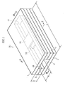
- the glucose sensor X1 shown in Figs. 1-3 is a disposable sensor designed to measure glucose concentration by colorimetry.
- the glucose sensor X1 comprises a first and a second plate members 1 and 2 bonded together via a pair of spacers 3.
- the glucose sensor X1 includes a capillary 4 defined by the above elements 1-3.
- the first and the second plate members 1 and 2 are made of e.g. PET, PMMA or vinylon to be transparent.
- the plate members 1 and 2 are respectively provided with a first and a second reagent portions 51 and 52, which are accommodated in the capillary 4.
- Each of the reagent portions 51 and 52 is in a solid state soluble in blood, and at least one of the reagent portions 51 and 52 contains color former. Therefore, when blood is introduced into the capillary 4, a liquid phase reaction system including glucose and color former is established in the capillary 4.
- color former whose absorption wavelength upon color development due to electron transfer is deviated from the absorption wavelength of blood.
- MTT 3-(4,5-Dimethyl-2-thiazolyl)-2,5-diphenyl-2H-tetrazolium bromide
- the first and the second reagent portions 51 and 52 may contain an electron mediator or an oxidoreductase. In such a case, the electron transfer between glucose and color former proceeds quickly, whereby the measurement time can be shortened.
- glucose dehydrogenase GDH
- glucose oxidase GOD
- PQQGDH PQQGDH
- electron mediator use may be made of [Ru (NH 3 ) 6 ] Cl 3 , K 3 [Fe (CN) 6 ] or methoxy-PMS (5-methylphenaziniummethylsulfate) , for example.
- the first and the second reagent portions 51 and 52 may have the same composition or may have different compositions. However, when an unstable reagent (highly reactive reagent) such as methoxy-PMS is used, it is preferable to separate such a reagent from other reagents. For instance, the unstable reagent is contained in the first reagent portion 51, whereas other reagents are contained in the second reagent portion 52.
- an unstable reagent highly reactive reagent
- methoxy-PMS methoxy-PMS
- the paired spacers 3 determine the distance between the first and the second plate members 1 and 2, i.e. the height H of the capillary 4 and also define the width W of the capillary 4.
- the paired spacers 3 are spaced from each other by a predetermined distance, and the distance corresponds to the width W of the capillary 4.
- the thickness of each spacer 3 corresponds to the height H of the capillary 4.
- the interior of the capillary 4 communicates with the outside through openings 40 and 41.
- the opening 40 is utilized for introducing blood into the capillary 4
- the opening 41 is utilized for discharging air from the capillary 4.
- the width W of the capillary 4 is set to 0.05mm to 10mm, whereas the height (facing distance) H of the capillary 4 is set to 30 ⁇ m to 1mm.
- the height H of the capillary 4 is set to 300 ⁇ m, and more preferably, no greater than 200 ⁇ m.
- the liquid phase reaction system 42 electrons extracted from glucose are supplied to the color former to cause the color former to develop color, whereby the liquid phase reaction system 42 is colored.
- the oxidoreductase and an electron mediator are contained in the first or the second reagent portion 51, 52, the oxidoreductase reacts specifically with glucose in the blood to extract electrons from glucose, and the electrons are supplied to the electron mediator and then to the color former. Therefore, the degree of color development of the color former (degree of coloring of the liquid phase reaction system) relates to the amount of electrons extracted from glucose, i.e. the glucose concentration.
- the degree of coloring of the liquid phase reaction system 42 is detected by irradiating the liquid phase reaction system 42 with light via the first plate member 1 and receiving the light passed through the liquid phase reaction system 42 and emitted from the second plate member 2.
- the light to irradiate the liquid phase reaction system 42 use is made of light having a wavelength which the color former upon color development absorbs much.
- the glucose concentration can be computed based on the intensity of the incident light impinging on the liquid phase reaction system 42 and the intensity of the transmitted light transmitted through the liquid phase reaction system 42.
- the first and the second reagent portions 51 and 52 are provided separately in the first and the second plate members 1 and 2 so as to face each other. Therefore, as to the height direction of the capillary 4, the length of diffusion of the color former which is necessary for equalizing the concentration of the color former is relatively short.
- the concentration of the color former cannot be equalized until the color former is diffused to the surface of the plate member which is not formed with a reagent portion.
- the concentration of the color former is high at the surface of each plate member while being low at an intermediate portion between the plate members in the stage in which the reagent portions 51 and 52 begin to dissolve. Therefore, to equalize the concentration of the color former, it is only necessary to diffuse the color former to the intermediate portion between the first and the second plate members.
- the diffusion length of the color former which is necessary for equalizing the concentration of the color former, is half of that in the case where a reagent portion is formed only at either one of the plate members.
- the provision of the reagent portions 51 and 52 at the first and the second plate members 1 and 2 shortens the time necessary for dispersing the color former uniformly in the liquid phase reaction system, and hence, shortens the reaction time.
- the concentration of unreacted glucose in the liquid phase reaction system is generally uniform. However, when the reaction proceeds to some degree, the concentration of unreacted glucose is low at a region where the concentration of the color former is high, whereas the concentration of unreacted glucose is high at a region where the concentration of the color former is low. Therefore, to shorten the measurement time, it is preferable to diffuse not only the color former but also unreacted glucose in the liquid phase reaction system to equalize the concentration. Since the first and the second reagent portions 51 and 52 are provided at the first and the second plate members 1 and 2 in the glucose sensor X1, the diffusion length of unreacted glucose necessary for equalizing the concentration is short because of the same reason as described above. Also from this point, it is concluded that the provision of the first and the second reagent portions 51 and 52 at the first and the second plate members 1 and 2 can shorten the reaction time.
- the measurement time can be further shortened by setting the facing distance H to no greater than 300 ⁇ m.
- the diffusion length necessary for equalizing the concentration of the color former or unreacted glucose can be reduced with respect to the height direction.
- the reaction necessary for causing the color former to develop color occurs easily. Therefore, the time taken for obtaining the intended reaction (coloring of the liquid phase reaction system) is shortened, whereby the measurement time can be shortened.
- a transparent substrate 6 is prepared.
- a plurality of first cutting lines 61 and a plurality of second cutting lines 62 extending perpendicularly to each other are defined.
- Each of the regions surrounded by the cutting lines 61 and 62 is a glucose sensor formation region 63.
- a plurality of double-sided tapes 64 are bonded as spaced from each other by a predetermined distance to cover the first cutting lines 61.
- a reagent portion 65 is formed at each of the glucose sensor formation regions 63 to provide a primary intermediate product 66.
- Each reagent portion 65 may be formed by applying a reagent solution containing a color former, an oxidoreductase and an electron mediator, and then drying the reagent solution by air blowing.
- another primary intermediate product 66 is prepared through the process steps described with reference to Figs. 5-7. Then, as shown in Fig. 8, the two primary intermediate products 66 are bonded together. Specifically, with the respective reagent portions 65 of the two primary intermediate products 66 facing each other, the two primary intermediate products are bonded to each other by utilizing the adhesive force of the double-sided tapes 64, whereby a secondary intermediate product (not shown) is provided. Finally, the secondary intermediate product is cut along the first and the second cutting lines 61 and 62, whereby glucose sensors X1 as shown in Figs. 1-3 are obtained.
- the glucose sensor of the present invention is not limited to the mode described in this embodiment but may be structured as shown in Figs. 9A-9D and Figs. 10A and 10B.
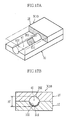
- the glucose sensor X2 shown in Fig. 9A includes a first plate member 1A formed with a first reagent portion 51A, and a second plate member 2A formed with a recess 20A which is rectangular in cross section and in which a reagent portion 52A is formed.
- the facing distance H is the distance between the bottom surface of the recess 20A and the first plate member 1A.
- the glucose sensor X3 shown in Fig. 9B includes a capillary 4B which is semicircular in cross section. Specifically, in the glucose sensor X3, the second plate 2B is formed with a recess 20B having a semicircular cross section, and a second reagent portion 52B is formed in the recess 20B. In the glucose sensor X3, the facing distance H is the distance between the deepest portion of the recess 20B and the first plate member 1B.
- the glucose sensor X4 shown in Fig. 9C includes a capillary 4C which is circular in cross section.
- the first and the second plate members 1C and 2C are respectively formed with recesses 10C and 20C which are semicircular in cross section, and a first and a second reagent portions 51C and 52C are formed in the recesses 10C and 20C, respectively.
- the reagent portions 51C and 52 of the glucose sensor X4 are continuously formed in the figure, the reagent portions 51C and 52C may be separated from each other.
- the facing distance H is the diameter of the capillary 4C in the thickness direction of the plate members 1C and 2C.
- the glucose sensor X5 shown in Fig. 9D includes a capillary 4D which is an elongated circle in cross section.
- the first and the second plate members 1D and 2D bonded together via a spacer 3D are respectively formed with recesses 10D and 20D which are semicircular in cross section , and a first and a second reagent portions 51D and 52D are respectively formed in the recesses 10D and 20D.
- the first and the second reagent portions 51D and 52D are separated from each other by the spacer 3D.
- the facing distance H is the distance between the respective deepest portions of the recesses 10D and 20D.
- the glucose sensor X6 shown in Figs. 10A and 10B includes a transparent cylindrical tube 7E in which a reagent portion 70E is formed.
- the glucose sensor X6 includes a capillary 71E which is circular in cross section.
- the glucose sensor X6 differs from the glucose sensor X4 shown in Fig. 9C in that the capillary 71E is defined by the cylindrical tube 7E.
- the facing distance H is the inner diameter of the circular tube 7E.
- the glucose sensor X7 shown in Figs. 11-14 is a disposable sensor designed to measure glucose concentration by colorimetry, and the basic structure is similar to that of the foregoing glucose sensor X1 (Figs. 1-3). Specifically, the glucose sensor X7 includes a first and a second plate members 1 and 2 bonded together via a pair of spacers 3F. The elements 1, 2 and 3F define a capillary 4F extending in the longitudinal direction of the first and the second plate members 1 and 2.
- the glucose sensor X7 differs from the foregoing glucose sensor X1 (Figs. 1-3) in height H' of the capillary 4F and arrangement of the reagent portion 51F.
- the height (facing distance) H' of the capillary is set to no greater than 150 ⁇ m.
- the height H' of the capillary 4F is set to no greater than 100 ⁇ m, and more preferably, no greater than 75 ⁇ m.
- the height H' of the capillary 4F can be adjusted by adjusting the thickness of the spacers 3F.
- the reagent portion 51F is provided only at the first plate member 1.
- the reagent portion 51F is in a solid state soluble in blood and contains a color former, an electron mediator and an oxidoreductase, for example.
- a color former the electron mediator and the oxidoreductase, those described in the first embodiment may be used.
- the measurement time can be shortened by setting the facing distance H' further smaller, i.e., to no greater than 150 ⁇ m.
- the diffusion length of an intended component (color former, oxidoreductase, electron mediator) contained in the reagent portion 51F which is necessary for equalizing the concentration of the intended component, becomes short with respect to the height direction.
- the diffusion length for uniformly dispersing unreacted glucose becomes shorter than that of ordinary glucose sensors with respect to the height direction.
- the reaction necessary for causing the color former to develop color occurs easily. Therefore, the time taken for obtaining the intended reaction (coloring of the liquid phase reaction system) is shortened, whereby the measurement time can be shortened.
- the glucose sensor of the present invention is not limited to the mode described in this embodiment and may be structured as shown in Figs. 15-17, for example.
- the glucose sensor X8 shown in Figs. 15A and 15B includes a first plate member 1G formed with a recess 10G which is rectangular in cross section, and a reagent portion 51G is formed at the bottom surface of the recess 10G.
- the facing distance H' is the distance between the bottom surface of the recess 10G and the second plate member 2G.
- the glucose sensor X9 shown in Figs. 16A and 16B includes a capillary 4H which is semicircular in cross section. Specifically, the first plate member 1H is formed with a recess 10H which is semicircular in cross section, and a reagent portion 51H is formed at the inner surface of the recess 10H. As shown in Fig. 16B, in the glucose sensor X9, the facing distance H' is the depth of the recess 10H.
- the glucose sensor X10 shown in Figs. 17A and 17B includes a capillary 4I which is circular in cross section.
- the first and the second plate members 1I and 21 are respectively formed with recesses 10I and 20I which are semicircular in cross section, and a reagent portion 51I is formed in the recess 10I of the first plate member 1I.
- the facing distance H' is the diameter of the capillary 41.
- a spacer is not interposed between the first and the second plate members.
- the facing distance becomes the sum of the above-described dimension and the thickness of the spacer.
- a glucose sensor which is designed to measure glucose concentration based on the strength of incident light and transmitted light.
- the present invention is also applicable to a glucose sensor which is designed to measures glucose concentration based on incident light and reflected light.
- the glucose sensor according to the first embodiment of the present invention is applicable not only to a glucose sensor for measuring glucose concentration by colorimetry but also to a glucose sensor for measuring glucose concentration by an electrode method.
- glucose sensors X1-X10 of the foregoing embodiments are designed to move a sample by a capillary force
- the sample may be moved by utilizing the motive power of a pump, for example.
- a structure for moving a sample need not necessarily be employed.
- the present invention is also applicable to the measurement of a component other than glucose which is contained in blood, such as cholesterol, for example. Further, the present invention is also applicable to the analysis of a sample other than blood, such as urine, for example.
- the influence of the height (facing distance) of a capillary of a glucose sensor on the measurement time when blood was used as a sample was examined by measuring the change of absorbance with time.
- glucose sensors (1)-(3) were used.
- the glucose sensors (1) - (3) are basically the same in structure but made different in height of the capillary (facing distance) by adjusting the thickness of respective double-sided tapes (spacers) as shown in Table 1.
- Each of the glucose sensors (1)-(3) was prepared as follows. First, on a first transparent plate made of PET and having dimensions of 10mm x 30mm x 0.2mm, a pair of double-sided tapes spaced from each other by 3mm were bonded. The double-sided tapes define the thickness of the capillary, and the thickness of the double-sided tapes used for each glucose sensor (1) - (3) is as shown in Table 1. Subsequently, a reagent solution having the composition shown in Table 1 was applied to a 3mm ⁇ 3mm region between the paired double-sided tapes, and then the reagent solution was dried by air blowing (30°C, 10%Rh), whereby a reagent portion was provided.
- the amount of the reagent solution applied in forming each glucose sensor (1) - (3) is as shown in Table 1.
- the application amount of the reagent solution is set in accordance with the capacity of respective capillaries so that the glucose sensors (1)-(3) become equal in reagent concentration when blood is introduced into the capillaries.
- a second transparent plate made of PET and having dimensions of 10mm x 30mm x 0.2mm was bonded to the first transparent plate via the double-sided tapes. In this way, glucose sensors (1) - (3) to be used in this Example were obtained.
- PQQGDH is the abbreviation of glucose dehydrogenase (GDH) having pyrroloquinoline quinone (PQQ) as a coenzyme
- PMS is the abbreviation of 5-methylphenazinium methylsulfate
- MMT is the abbreviation of 3-(4,5-Dimethyl-2-thiazolyl)-2
- 5-diphenyl-2H-tetrazolium bromide PIPES is the abbreviation of Piperazine-1, 4-bis(2-ethanesulfonic acid).
- the absorbance in each of the glucose sensors (1)-(3) was measured over time with respect to blood having glucose concentration of about 0mg/dL, 200mg/dL, 400mg/dL or 600mg/dL.
- the region provided with the reagent portion was irradiated with light along the thickness direction, and the light transmitted through the glucose sensor was received.
- the light transmitted through the glucose sensor was received.
- 630nm light was directed by using a light emitting diode.
- the transmitted light was received by a photodiode.
- ABS ( absorbance ) log ( l 1 / l 2 )
- l 1 represents the intensity of incident light
- l 2 represents the intensity of transmitted light
- the change of the absorbance with time is small.
- the absorbance does not become sufficiently close to the maximum absorbance even after the lapse of 30 seconds from the start of blood introduction. Therefore, in the glucose sensor (1) , it is difficult to measure the glucose concentration within 30 seconds after the start of the blood introduction. To accurately measure the glucose concentration within 30 seconds after the start of the blood introduction, the measurement range cannot help being narrowed.
- the absorbance becomes sufficiently close to the maximum absorbance after the lapse of about 10 seconds from the start of the blood introduction even when the glucose concentration is 600mg/dL. Therefore, in the glucose sensor (2), the accurate measurement of glucose concentration is possible after the lapse of about 10 seconds from the start of the blood introduction at least in the glucose concentration range of 0 to 600mg/dL.
- the absorbance becomes sufficiently close to the maximum absorbance after the lapse of about five seconds from the start of the blood introduction even when the glucose concentration is 600mg/dL. Therefore, in the glucose sensor (3), the accurate measurement of the glucose concentration is possible after the lapse of about five seconds from the start of the blood introduction at least in the glucose concentration range of 0 to 600mg/dL.
- the measurement time can be shortened by reducing the distance (facing distance) of the reagent portions in the capillary in the normal direction, e.g. to no greater than 150 ⁇ m, and more preferably, no greater than 75 ⁇ m.
- a reagent portion (See Figs. 1-3) is formed at each of the first and the second plate members.
- the glucose sensor (4) was prepared by bonding a pair of double-sided tapes on a first plate member and forming a first reagent portion between the double-sided tapes while bonding a pair of double-sided tapes on a second plate member and forming a second reagent portion between the double-sided tapes, and then bonding the first and the second plate members together so that the first and the second reagent portions face each other.
- the glucose sensor (4) only the elements which differ from those of the glucose sensors (1)-(3) are described in Table 2, and other informations which are not described in Table 2 are the same as those of the glucose sensors (1)-(3).
- Each of the glucose sensors (5) and (6) includes a reagent portion formed at the first plate member only, and was made similarly to the glucose sensors (1) - (3) of Example 1 to have the structure shown in Table 2 below.
- the absorbance was measured over time by using the glucose sensors (4) - (6) similarly to Example 1.
- the absorbance was measured with respect to three kinds of glucose solutions which differ in concentration (0mg/dL, 200mg/dL, 400mg/dL).
- the measurement results of change of absorbance with time in each of the glucose sensors (4)-(6) are respectively shown in Figs. 19A-19C.
- the absorbance becomes sufficiently close to the maximum absorbance after the lapse of about 10 seconds from the start of the blood introduction even when the glucose concentration is 600mg/dL. Therefore, with a glucose sensor which includes two reagent portions facing each other like the glucose sensor (4), the accurate measurement of glucose concentration is possible after the lapse of about 10 seconds from the start of the blood introduction at least in the glucose concentration range of 0 to 600mg/dL.
- the change of absorbance with time is small.
- the absorbance does not become sufficiently close to the maximum absorbance even after the lapse of 30 seconds from the start of blood introduction. Therefore, in the glucose sensor (5) which includes a reagent portion on one side only, it is difficult to measure the glucose concentration within 30 seconds after the start of the blood introduction even when the height (facing distance) of the capillary and the composition of the reagent portion are the same as those of the glucose sensor (4). To accurately measure the glucose concentration within 30 seconds after the start of the blood introduction, the measurement range cannot help being narrowed.
- the glucose sensor (4) which includes two reagent portions facing each other have substantially the same advantages as those of a glucose sensor having a small facing distance (glucose sensors (2) and (3) of Example 1).
- the provision of reagent portions facing each other provides the following advantages. Firstly, the measurement time can be shortened even when the facing distance is relatively large. Secondly, by setting the facing distance relatively small, the measurement can be performed in a shorter period of time than is possible in the case where a reagent portion is formed on one plate member only. Therefore, with a glucose sensor including two reagent portions facing each other, the measurement time can be considerably shortened.
Landscapes
- Chemical & Material Sciences (AREA)
- Health & Medical Sciences (AREA)
- Dispersion Chemistry (AREA)
- Analytical Chemistry (AREA)
- General Health & Medical Sciences (AREA)
- Hematology (AREA)
- Clinical Laboratory Science (AREA)
- Chemical Kinetics & Catalysis (AREA)
- Investigating Or Analysing Biological Materials (AREA)
- Investigating Or Analysing Materials By The Use Of Chemical Reactions (AREA)
Applications Claiming Priority (3)
| Application Number | Priority Date | Filing Date | Title |
|---|---|---|---|
| JP2003111948A JP2004317307A (ja) | 2003-04-16 | 2003-04-16 | 試薬部対面分析用具およびこの分析用具の製造方法 |
| JP2003111950A JP2004317308A (ja) | 2003-04-16 | 2003-04-16 | 小ギャップ比色分析用具 |
| PCT/JP2004/005434 WO2004092725A1 (ja) | 2003-04-16 | 2004-04-15 | 試薬の拡散距離が短縮された分析用具およびその製造方法 |
Publications (2)
| Publication Number | Publication Date |
|---|---|
| EP1615031A1 true EP1615031A1 (de) | 2006-01-11 |
| EP1615031A4 EP1615031A4 (de) | 2011-01-12 |
Family
ID=33302217
Family Applications (1)
| Application Number | Title | Priority Date | Filing Date |
|---|---|---|---|
| EP04727733A Withdrawn EP1615031A4 (de) | 2003-04-16 | 2004-04-15 | Analysewerkzeug mit reduziertem abstand der diffusion eines reagens und verfahren zur herstellung davon |
Country Status (3)
| Country | Link |
|---|---|
| US (1) | US20070053790A1 (de) |
| EP (1) | EP1615031A4 (de) |
| WO (1) | WO2004092725A1 (de) |
Cited By (3)
| Publication number | Priority date | Publication date | Assignee | Title |
|---|---|---|---|---|
| EP2017006A1 (de) * | 2007-07-20 | 2009-01-21 | Koninklijke Philips Electronics N.V. | Mikrofluidische Verfahren und Systeme zur Verwendung bei der Analytdetektion |
| EP1712919A4 (de) * | 2004-01-07 | 2009-08-12 | Arkray Inc | Analysegerät mit verbesserter anordnung des reagentienbereichs und analyseverfahren |
| EP2211172A1 (de) * | 2007-10-31 | 2010-07-28 | ARKRAY, Inc. | Analyseinstrument und herstellungsverfahren dafür |
Families Citing this family (3)
| Publication number | Priority date | Publication date | Assignee | Title |
|---|---|---|---|---|
| CN103003440B (zh) * | 2010-07-23 | 2015-11-25 | 霍夫曼-拉罗奇有限公司 | 含两性离子缓冲液的组合物及其在电分析装置和方法中的用途 |
| DE102011108008A1 (de) | 2011-07-19 | 2013-01-24 | Harry Gaus | Dekanterzentrifuge |
| EP4116405A1 (de) * | 2021-07-07 | 2023-01-11 | Koninklijke Philips N.V. | Fluidische vorrichtungen und verfahren zur herstellung davon |
Citations (5)
| Publication number | Priority date | Publication date | Assignee | Title |
|---|---|---|---|---|
| EP0849589A1 (de) * | 1996-12-20 | 1998-06-24 | Matsushita Electric Industrial Co., Ltd. | Cholesterinsensor und Verfahren zu seiner Herstellung |
| JPH11304748A (ja) * | 1998-04-23 | 1999-11-05 | Omron Corp | バイオセンサ |
| WO2001061041A2 (en) * | 2000-02-18 | 2001-08-23 | Aclara Biosciences Inc. | Multiple-site reaction device and method |
| WO2002033407A1 (en) * | 2000-10-17 | 2002-04-25 | Abbott Laboratories | Diagnostic assay for a sample of biological fluid |
| US6471839B1 (en) * | 1999-05-20 | 2002-10-29 | Matsushita Electric Industrial Co., Ltd. | Biosensor |
Family Cites Families (6)
| Publication number | Priority date | Publication date | Assignee | Title |
|---|---|---|---|---|
| JPH03223674A (ja) * | 1989-11-30 | 1991-10-02 | Mochida Pharmaceut Co Ltd | 反応容器 |
| AU642444B2 (en) * | 1989-11-30 | 1993-10-21 | Mochida Pharmaceutical Co., Ltd. | Reaction vessel |
| US5962215A (en) * | 1996-04-05 | 1999-10-05 | Mercury Diagnostics, Inc. | Methods for testing the concentration of an analyte in a body fluid |
| JP4250692B2 (ja) * | 1998-10-15 | 2009-04-08 | アークレイ株式会社 | 体液測定装置および装着体 |
| JP2002333420A (ja) * | 2001-03-07 | 2002-11-22 | Matsushita Electric Ind Co Ltd | バイオセンサおよび基質の定量方法 |
| US6821410B2 (en) * | 2001-03-07 | 2004-11-23 | Matsushita Electric Industrial Co., Ltd. | Biosensor and method of substrate quantification |
-
2004
- 2004-04-15 WO PCT/JP2004/005434 patent/WO2004092725A1/ja active Application Filing
- 2004-04-15 US US10/553,336 patent/US20070053790A1/en not_active Abandoned
- 2004-04-15 EP EP04727733A patent/EP1615031A4/de not_active Withdrawn
Patent Citations (5)
| Publication number | Priority date | Publication date | Assignee | Title |
|---|---|---|---|---|
| EP0849589A1 (de) * | 1996-12-20 | 1998-06-24 | Matsushita Electric Industrial Co., Ltd. | Cholesterinsensor und Verfahren zu seiner Herstellung |
| JPH11304748A (ja) * | 1998-04-23 | 1999-11-05 | Omron Corp | バイオセンサ |
| US6471839B1 (en) * | 1999-05-20 | 2002-10-29 | Matsushita Electric Industrial Co., Ltd. | Biosensor |
| WO2001061041A2 (en) * | 2000-02-18 | 2001-08-23 | Aclara Biosciences Inc. | Multiple-site reaction device and method |
| WO2002033407A1 (en) * | 2000-10-17 | 2002-04-25 | Abbott Laboratories | Diagnostic assay for a sample of biological fluid |
Non-Patent Citations (1)
| Title |
|---|
| See also references of WO2004092725A1 * |
Cited By (8)
| Publication number | Priority date | Publication date | Assignee | Title |
|---|---|---|---|---|
| EP1712919A4 (de) * | 2004-01-07 | 2009-08-12 | Arkray Inc | Analysegerät mit verbesserter anordnung des reagentienbereichs und analyseverfahren |
| US7780828B2 (en) | 2004-01-07 | 2010-08-24 | Arkray, Inc. | Analytical instrument having improved arrangement of reagent section and analytical method |
| EP2017006A1 (de) * | 2007-07-20 | 2009-01-21 | Koninklijke Philips Electronics N.V. | Mikrofluidische Verfahren und Systeme zur Verwendung bei der Analytdetektion |
| WO2009013658A2 (en) | 2007-07-20 | 2009-01-29 | Koninklijke Philips Electronics N.V. | Microfluidic methods and systems for use in detecting analytes |
| WO2009013658A3 (en) * | 2007-07-20 | 2009-03-12 | Koninkl Philips Electronics Nv | Microfluidic methods and systems for use in detecting analytes |
| EP2211172A1 (de) * | 2007-10-31 | 2010-07-28 | ARKRAY, Inc. | Analyseinstrument und herstellungsverfahren dafür |
| EP2211172A4 (de) * | 2007-10-31 | 2014-11-26 | Arkray Inc | Analyseinstrument und herstellungsverfahren dafür |
| US9063077B2 (en) | 2007-10-31 | 2015-06-23 | Arkray, Inc. | Analysis tool and manufacturing method thereof |
Also Published As
| Publication number | Publication date |
|---|---|
| EP1615031A4 (de) | 2011-01-12 |
| US20070053790A1 (en) | 2007-03-08 |
| WO2004092725A1 (ja) | 2004-10-28 |
Similar Documents
| Publication | Publication Date | Title |
|---|---|---|
| EP1712919B1 (de) | Analysegerät mit verbesserter anordnung des reagentienbereichs und analyseverfahren | |
| US9662057B2 (en) | Integrated sample acquisition and analyte measurement method | |
| AU765872B2 (en) | Small volume (in vitro) analyte sensor with diffusible or non-leachable redox mediator | |
| EP1621887B1 (de) | Analytischer Teststreifen mit Kontrollzone | |
| EP1637889A1 (de) | Analysatorgerät mit anteil zur speicherung von flüssigkeit | |
| WO2005098431A1 (en) | Analyte test system for determining the concentration of an analyte in a physiological fluid | |
| WO2007052648A1 (ja) | 試料分析用ディスク | |
| EP1615031A1 (de) | Analysewerkzeug mit reduziertem abstand der diffusion eines reagens und verfahren zur herstellung davon | |
| EP3578634B1 (de) | Blutzuckermesschip und blutzuckermessvorrichtungssatz | |
| EP2617834B1 (de) | Verfahren zur Herstellung einer Trockenreagenz, Trockenreagenz und Analysewerkzeug damit | |
| JP2004317307A (ja) | 試薬部対面分析用具およびこの分析用具の製造方法 | |
| CN1774628B (zh) | 缩短试药的扩散距离的分析用具及其制造方法 | |
| US20040235185A1 (en) | Fluorimetric determination of analytes by amine-N-oxides as redox indicators | |
| WO2023112442A1 (ja) | 生体成分濃度測定試薬、測定方法およびセンサ | |
| JP2023087327A (ja) | 生体成分濃度測定試薬、測定方法およびセンサ | |
| AU2003271369B2 (en) | Small volume in vitro analyte sensor with diffusible or non-leachable redox mediator | |
| MXPA06010066A (en) | Analyte test system for determining the concentration of an analyte in a physiological fluid |
Legal Events
| Date | Code | Title | Description |
|---|---|---|---|
| PUAI | Public reference made under article 153(3) epc to a published international application that has entered the european phase |
Free format text: ORIGINAL CODE: 0009012 |
|
| 17P | Request for examination filed |
Effective date: 20051027 |
|
| AK | Designated contracting states |
Kind code of ref document: A1 Designated state(s): AT BE BG CH CY CZ DE DK EE ES FI FR GB GR HU IE IT LI LU MC NL PL PT RO SE SI SK TR |
|
| AX | Request for extension of the european patent |
Extension state: AL HR LT LV MK |
|
| DAX | Request for extension of the european patent (deleted) | ||
| A4 | Supplementary search report drawn up and despatched |
Effective date: 20101210 |
|
| 17Q | First examination report despatched |
Effective date: 20110304 |
|
| STAA | Information on the status of an ep patent application or granted ep patent |
Free format text: STATUS: THE APPLICATION IS DEEMED TO BE WITHDRAWN |
|
| 18D | Application deemed to be withdrawn |
Effective date: 20111215 |