EP1613013B1 - Verfahren und Vorrichtung zur Verminderung von Amplitudenschwankungen und Störungen in Kommunikationssignalen mit eingesetzten Pilotsymbolen - Google Patents
Verfahren und Vorrichtung zur Verminderung von Amplitudenschwankungen und Störungen in Kommunikationssignalen mit eingesetzten Pilotsymbolen Download PDFInfo
- Publication number
- EP1613013B1 EP1613013B1 EP05018036A EP05018036A EP1613013B1 EP 1613013 B1 EP1613013 B1 EP 1613013B1 EP 05018036 A EP05018036 A EP 05018036A EP 05018036 A EP05018036 A EP 05018036A EP 1613013 B1 EP1613013 B1 EP 1613013B1
- Authority
- EP
- European Patent Office
- Prior art keywords
- pilot symbols
- user stations
- pilot
- base station
- symbol
- Prior art date
- Legal status (The legal status is an assumption and is not a legal conclusion. Google has not performed a legal analysis and makes no representation as to the accuracy of the status listed.)
- Expired - Lifetime
Links
Images


Classifications
-
- H—ELECTRICITY
- H04—ELECTRIC COMMUNICATION TECHNIQUE
- H04B—TRANSMISSION
- H04B1/00—Details of transmission systems, not covered by a single one of groups H04B3/00 - H04B13/00; Details of transmission systems not characterised by the medium used for transmission
- H04B1/76—Pilot transmitters or receivers for control of transmission or for equalising
-
- H—ELECTRICITY
- H04—ELECTRIC COMMUNICATION TECHNIQUE
- H04W—WIRELESS COMMUNICATION NETWORKS
- H04W52/00—Power management, e.g. TPC [Transmission Power Control], power saving or power classes
- H04W52/04—TPC
-
- H—ELECTRICITY
- H04—ELECTRIC COMMUNICATION TECHNIQUE
- H04B—TRANSMISSION
- H04B1/00—Details of transmission systems, not covered by a single one of groups H04B3/00 - H04B13/00; Details of transmission systems not characterised by the medium used for transmission
- H04B1/69—Spread spectrum techniques
- H04B1/707—Spread spectrum techniques using direct sequence modulation
- H04B1/7097—Interference-related aspects
- H04B1/7103—Interference-related aspects the interference being multiple access interference
-
- H—ELECTRICITY
- H04—ELECTRIC COMMUNICATION TECHNIQUE
- H04J—MULTIPLEX COMMUNICATION
- H04J13/00—Code division multiplex systems
- H04J13/0007—Code type
- H04J13/004—Orthogonal
- H04J13/0048—Walsh
-
- H—ELECTRICITY
- H04—ELECTRIC COMMUNICATION TECHNIQUE
- H04J—MULTIPLEX COMMUNICATION
- H04J13/00—Code division multiplex systems
- H04J13/10—Code generation
- H04J13/12—Generation of orthogonal codes
-
- H—ELECTRICITY
- H04—ELECTRIC COMMUNICATION TECHNIQUE
- H04L—TRANSMISSION OF DIGITAL INFORMATION, e.g. TELEGRAPHIC COMMUNICATION
- H04L27/00—Modulated-carrier systems
- H04L27/26—Systems using multi-frequency codes
- H04L27/2601—Multicarrier modulation systems
- H04L27/2614—Peak power aspects
- H04L27/2615—Reduction thereof using coding
-
- H—ELECTRICITY
- H04—ELECTRIC COMMUNICATION TECHNIQUE
- H04B—TRANSMISSION
- H04B2201/00—Indexing scheme relating to details of transmission systems not covered by a single group of H04B3/00 - H04B13/00
- H04B2201/69—Orthogonal indexing scheme relating to spread spectrum techniques in general
- H04B2201/707—Orthogonal indexing scheme relating to spread spectrum techniques in general relating to direct sequence modulation
- H04B2201/70701—Orthogonal indexing scheme relating to spread spectrum techniques in general relating to direct sequence modulation featuring pilot assisted reception
-
- H—ELECTRICITY
- H04—ELECTRIC COMMUNICATION TECHNIQUE
- H04B—TRANSMISSION
- H04B2201/00—Indexing scheme relating to details of transmission systems not covered by a single group of H04B3/00 - H04B13/00
- H04B2201/69—Orthogonal indexing scheme relating to spread spectrum techniques in general
- H04B2201/707—Orthogonal indexing scheme relating to spread spectrum techniques in general relating to direct sequence modulation
- H04B2201/70706—Orthogonal indexing scheme relating to spread spectrum techniques in general relating to direct sequence modulation with means for reducing the peak-to-average power ratio
-
- H—ELECTRICITY
- H04—ELECTRIC COMMUNICATION TECHNIQUE
- H04J—MULTIPLEX COMMUNICATION
- H04J13/00—Code division multiplex systems
- H04J13/0007—Code type
- H04J13/004—Orthogonal
-
- H—ELECTRICITY
- H04—ELECTRIC COMMUNICATION TECHNIQUE
- H04L—TRANSMISSION OF DIGITAL INFORMATION, e.g. TELEGRAPHIC COMMUNICATION
- H04L25/00—Baseband systems
- H04L25/02—Details ; arrangements for supplying electrical power along data transmission lines
- H04L25/03—Shaping networks in transmitter or receiver, e.g. adaptive shaping networks
- H04L25/03006—Arrangements for removing intersymbol interference
- H04L2025/03777—Arrangements for removing intersymbol interference characterised by the signalling
Definitions
- the invention relates to communication systems. More particularly, the invention relates to methods and apparatus for reducing amplitude and interference in wireless communication systems using inserted pilot symbols.
- CDMA code division multiple access
- CDMA modulation techniques provide capacity improvements over other techniques based in part on CDMA's use of orthogonal functions.
- the CDMA codes are generated by, e.g. , Walsh functions that mathematically form an orthogonal set. Thus, any two Walsh functions are orthogonal to each other, and signals encoded with two separate Walsh functions should cause no mutual interference if they are time aligned.
- An example of Walsh functions employed in a CDMA communication system is disclosed in U.S. Patent No. 5,602,883 , entitled "METHOD AND APPARATUS FOR USING WALSH SHIFT KEYING IN A SPREAD SPECTRUM COMMUNICATION SYSTEM," assigned to the assignee of the present invention.
- CDMA Since CDMA employs a wideband signal, it spreads the signal energy over a wide bandwidth. Therefore, frequency selective fading affects only a small part of the CDMA signal bandwidth.
- CDMA also provides space or path diversity through multiple signal paths that simultaneously link a mobile station or user with two or more cell-sites. Furthermore, CDMA can exploit the multipath environment by allowing a signal arriving with different propagation delays to be received and processed separately. Examples of path diversity are illustrated in U.S. Patent No. 5,101,501 entitled “METHOD AND SYSTEM FOR PROVIDING A SOFT HANDOFF IN COMMUNICATIONS IN A CDMA CELLULAR TELEPHONE SYSTEM," and U.S. Patent No. 5,109,390 entitled “DIVERSITY RECEIVER IN A CDMA CELLULAR TELEPHONE SYSTEM,” both assigned to the assignee of the present invention.
- each base station transmits pilot, sync, paging and forward traffic channels to its users.
- the pilot channel is an unmodulated, direct-sequence spread spectrum signal transmitted continuously by each base station.
- the pilot channel allows each user to acquire the timing of the channels transmitted by the base station, and provides a phase reference for coherent demodulation.
- the pilot channel also provides a means for signal strength comparisons between base stations to determine when to hand off between base stations (such as when moving between cells).
- CDMA modulation techniques require that all transmitters be under precise power control to manage interference in the system. If the transmission power of signals transmitted by a base station to a user (the forward link) are too high, it can create problems such as interfering with other users. As a result, most base stations have a fixed amount of power at which to transmit signals, and therefore can transmit to only a limited number of users. Alternatively, if the transmission power of signals transmitted by the base station is too low, then some users can receive multiple erroneous transmitted frames. Terrestrial channel fading and other known factors also affect the transmission power of signals transmitted by the base station. Thus, each base station needs to adjust the transmission power of the signals it transmits to its users. A method and apparatus for controlling transmission power is disclosed in U.S. Patent No. 5,056,109 , entitled "METHOD AND APPARATUS FOR CONTROLLING TRANSMISSION POWER IN A CDMA CELLULAR TELEPHONE SYSTEM,” assigned to the assignee of the present invention.
- Recent CDMA modulation techniques have been proposed using dedicated time multiplexed (“DTMP”) pilot symbols.
- DTMP dedicated time multiplexed
- CCMP common code multiplexed pilot
- pilot symbols are time multiplexed on each user's traffic channel. Each user sequentially de-spreads the pilot symbols (and information symbols).
- CCMP common code multiplexed pilot
- one co-channel is dedicated to broadcasting a pilot signal. No pilot symbols are multiplexed with dedicated channels, and all users de-spread both the pilot symbols and the modulated information signals in parallel.
- the base station must employ a fraction of its total power for pilot symbols and pilot data for each user.
- the total amount of power required for the pilot symbols and pilot data is based on a sum of the power required for all pilot symbols and pilot data for all of the base station's users.
- the CCMP approach need only allocate a fraction of its total power to the common pilot based on a maximum pilot power required by the "worst-case" user. Additionally, the DTMP approach may suffer from further shortcomings.
- PCT Publication number WO 98/18217 discloses a method for altering transmission timings among a plurality of parallel discontinuous transmissions is disclosed.
- each transmission connection is offset by a predetermined amount in order to generate interference that is evenly spread in time between cells.
- pilot symbols transmitted to different mobile stations or users in the DTMP approach add linearly and cause large peak to average amplitude variations.
- Such amplitude variations require either large power amplifiers and/or cause interference in the system.
- a sign or value is identical in one position of each orthogonal code assigned to concurrent users (the "common sign chip position"), which can linearly add to produce a large amplitude.
- the base station multiplies the signals of each user by a plus or minus random variable or phase rotation between 0 and 360 degrees, such as 0 or 180 degrees.
- the orthogonality of the codes is still maintained between the orthogonal functions, but the value of the common sign chip position of some codes is varied.
- the user station can determine the value of the random variable by either observing the sign of the Walsh demodulation, or by receiving additional data sent from the base station.
- the base station transmits empty symbols or chips in the common sign position of each orthogonal function.
- the user station then reinserts the missing chip after receiving the remainder of the orthogonal function sequence.
- the user station can reconstruct the first chip with the Walsh functions. For example, if all the transmitted Walsh functions would sum to 0 if fully sent, then the user station sums all of the received Walsh functions (without the first chips) over all the Walsh chips. The negative of this sum is the value that the received signal would have had if the Walsh functions were fully transmitted. If one of the Walsh functions did not sum to 0 (for example, all chips were equal to 1), then a first Walsh demodulation of all the received Walsh functions provides simultaneous equations for solving for the first Walsh chip amplitudes.
- the base station instead of providing each user station with its own pilot symbols, the base station first identifies symbol positions common to different users. For example, four users may expect to receive a pilot symbol in symbol position six. Instead of transmitting four separate pilot symbols, the base station only transmits one pilot symbol to be used by all four users. This is a hybrid DTMP and CCMP approach. Individual pilot symbols are effectively shared or combined among users to provide the pilot symbols required for all user stations. Pilot symbols are not sent in symbol positions where no user station expects to find any pilot symbol. Not only does this third class of solutions reduce the peak to average amplitude problem, but also reduces the number of symbols transmitted, to thereby reduce interference among transmitted channels.
- the base station shifts each orthogonal code by a random amount.
- the user station receives information regarding the random shifts for each channel to thereby unshift the channels and retain the orthogonality.
- Such random shifts effectively "shuffle" the common sign chip position in the orthogonal codes, thereby reducing the peak to average amplitude problem noted above.
- one aspect of the invention is for use in a communication system having a base station and several user stations that exchange communication signals with the base station.
- a method for reducing transmission signal power of transmitted communication signals includes: (a) receiving channel data for transmission on several channels, wherein the channel data includes pilot symbol data; (b) combining orthogonal codes with the received channel data, wherein each orthogonal code has at least one common chip position, and wherein the common chip position has a same value for each orthogonal code; and (c) before transmitting the channel data combined with the orthogonal codes, altering the common chip position of at least one of the orthogonal codes to reduce a combined amplitude resulting from simultaneous transmission and addition of the common chip position for the several channels.
- a method includes: (a) receiving channel data for transmission on several channels to several user stations, wherein the channel data includes pilot symbol data; (b) determining symbol positions in which each of the several user stations expect to find pilot symbols; and (c) transmitting to the several user stations pilot symbols only in symbol positions that the several user stations expect to find pilot symbols, and failing to transmit pilot symbols in other symbol positions.
- a user station in yet another aspect of the invention, includes a receiver and a processor.
- the user station is for use in a communications system having a base station and several other user stations. All of the user stations exchange communication signals with the base station.
- the receiver receives channel data from one of several channels, wherein the channel data includes pilot symbol data encoded with one of several orthogonal codes, and wherein each orthogonal code has at least one common chip position.
- the common chip position has a same value for each orthogonal code.
- the common chip position of the one received orthogonal code is altered.
- the processor which is coupled to the receiver, returns the altered one orthogonal code to an original state.
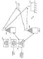
- FIG. 1 illustrates an exemplary cellular subscriber communication system 100, which uses multiple access techniques such as CDMA for communicating between users of user stations (e.g., mobile telephones) and cell-sites or base stations.
- a mobile user station 102 communicates with a base station controller 104 by means of one or more base stations 106a, 106b, etc.
- a fixed user station 108 communicates with the base station controller 104, but by means of only one or more predetermined and proximate base stations, such as the base stations 106a and 106b.
- the base station controller 104 is coupled to and typically includes interface and processing circuitry for providing system control to the base stations 106a and 106b.
- the base station controller 104 may also be coupled to and communicate with other base stations, and possibly even other base station controllers.
- the base station controller 104 is coupled to a mobile switching center 110, which in turn is coupled to a home location register 112.
- the base station controller 104 and the mobile switching center 110 compare registration signals received from the user stations to data contained in the home location register 112, as is known in the art. Soft handoffs may occur between the base station controller 104 and other base controllers, and even between the mobile switching center 110 and other mobile switching centers, as is known by those skilled in the art.
- the base station controller 104 When the system 100 processes telephone or data traffic calls, the base station controller 104 establishes, maintains and terminates the wireless link with the mobile station 102 and the fixed station 108, while the mobile switching center 110 establishes, maintains and terminates communications with a public switched telephone network (PSTN). While the discussion below focuses on signals transmitted between the base station 106a and the mobile station 102, those skilled in the art will recognize that the discussion equally applies to other base stations, and to the fixed station 108.
- PSTN public switched telephone network
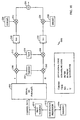
- a modulator and encoder 200 for use in the base station 106a includes a serial to parallel converter 202 that receives a serial stream of channel data and outputs a parallel stream of data on in-phase ("I") and quadrature ("Q") channels.
- An orthogonal code generator 204 generates orthogonal codes, such as Walsh codes.
- a phase rotator 206 generates a different phase rotation between 0 and 360 for Walsh codes output from the orthogonal code generator 204. For example, under a simpler embodiment, the phase rotator 206 generates phase rotations of 0 or 180 degrees. As a result, the phase rotator 206 randomly multiplies a plus or minus one value to the Walsh codes. While the phase rotator 206 is shown coupled to the orthogonal code generator 204, the phase rotator can be coupled to other elements in the encoder 200.
- a first pair of multipliers 208 and 210 multiply the randomly inverted Walsh codes with the in-phase and quadrature signals, respectively.
- the channel data input to the modulator 200 includes inserted pilot symbols to which orthogonal codes from the orthogonal code generator 204 are multiplied.
- orthogonal codes In all orthogonal codes, at least one row or column in a matrix of orthogonal codes have the same sign (the "common sign chip position").
- the pilot symbols typically include a series of +1 values for all chip positions for the symbol.
- the plus one value pilot symbols for multiple mobile stations would add together to increase the peak to average amplitude, when the common sign chip positions of the orthogonal codes are aligned, as described below.
- a second pair of multipliers 212 and 214 multiply a scrambling code, output from a scrambling code generator 216, to the signals output from the multipliers 208 and 210, respectively. While only one channel is shown, the encoder 200 combines signals from all Walsh channels (with some gain on each channel) before being scrambled or spread by the scrambling code generator 216.
- a pair of filters 218 and 220 such as pulse filters, filter the outputs from the multipliers 212 and 214 on the in-phase and quadrature channels, respectively.
- a third pair of multipliers 222 and 224 multiply the filtered signals with carrier frequencies provided by cos ( ⁇ t) and sin ( ⁇ t) generators 226 and 228 on the in-phase and quadrature channels, respectively.
- an adder 230 adds the signals from the third pair of multipliers 222 and 224, prior to amplification and transmission to the mobile station 102.
- FIGS. 1 , 2 and the other figures are of conventional design and operation. Thus, such blocks need not be described in further detail, because they will be understood by those skilled in the relevant art. Any additional description is omitted for brevity and to avoid obscuring the detailed description of the invention. Any modifications necessary to the blocks of the communication system 100 of FIG.1 , the encoder 200 of FIG. 2 , or other systems can be readily made by one skilled in the relevant art based on the detailed description provided herein.
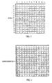
- a portion of the first 14 rows and 11 columns of a Walsh 128 matrix is shown, which reflects an example of orthogonal codes generated by the orthogonal code generator 204.
- the first chip position i . e ., first column
- Other orthogonal codes may employ matrices having a common sign chip position that is not necessarily in the first column (i.e., not in the first chip position).
- the first Walsh chips add linearly.
- the k'th row is the sum of the first (k+1) rows in the Walsh matrix, which corresponds to (k+1) pilot symbols of different mobile stations being added.
- the first Walsh chips add to a value of 16 with 16 mobile stations.
- the power of the first Walsh chip position grows approximately at the square of an N number of mobile stations, while the variance from all channels grows linearly with N, thereby making results worse as N increases. While greater smoothing of amplitude results as N increases, an increase in N is found to only offset the linear growth in amplitude.
- each frame includes 16 slots
- a full rate call has slots consisting of four pilot symbols, one power control bit and 15 data symbols
- 1/8 rate calls include four pilot symbols, one power control bit, two data symbols and 13 empty symbols transmitted randomly as bursts relative to each other.
- Calls are allocated frame (and slot) offset positions with a resolution of one symbol.
- a reference slot has zero offset and all 1/8 rate calls have slot offsets of 0-19 relative to the reference slot.
- the total number of call symbols in a symbol position i is determined as follows.
- the full rate calls occupy all the symbol positions, while the number of 1/8 rate calls, which have offsets of i -6, i -5, i -4, i -3, i -2, i -1, i , have symbols between calls overlapping in position i .
- i-j ⁇ 0, such symbols are assumed to result from a burst initiating in a previous slot.
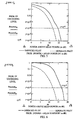
- the signal x for N channels can be well modelled with a Gaussian approximation.
- x 2 is a non-central Chi-squared random variable with non-centrality parameter p.
- the amplitudes of inserted pilot symbols add to thereby increase the peak to average power ratio for a number N equal to 20 and 120 calls, respectively.
- the peak to average ratio of inserted pilot symbols is approximately 15 and 17 dB as shown in FIGS. 5 and 6 , respectively. This compares to a ratio of about 12 dB for a separate pilot transmitted continuously at the full rate (shown as the dotted line graph in FIGS. 5 and 6 ).
- this peak to average ratio increase results from the common sign chip position in orthogonal codes used in CDMA coding.
- the modulator 200 of FIG. 2 employs the phase rotator 206 to randomly multiply a plus or minus one value to the orthogonal codes output from the orthogonal code generator 204. For example, assume that three calls are assigned Walsh codes 11-1-11-1-111-1-1..., 11-1-1-1-11111-1-1..., and 1-11-1-11-11-1..., corresponding respectively to rows 2, 6 and 13 of the Walsh matrix of FIG. 3 .
- the orthogonal code generator 204 can algorithmically generate the orthogonal codes, such as the Walsh codes.
- the phase rotator 206 can be a pseudorandom number generator.
- the orthogonal code generator 204 and phase rotator 206 can be combined to form a single unit that randomly generates orthogonal codes having phase variations.
- the orthogonal code generator 204 can be a stored table of orthogonal codes.
- the base station 106a provides an arbitrary phase offset for each channel, including the channels received by the mobile station 102.
- the mobile station 102 decodes the data symbols by comparing them to the phase of the received pilot symbols.
- the mobile station 102 does not necessarily determine the original phase of the orthogonal code (before being multiplied by a plus or minus one from the phase rotator 206), but instead determines the relative phase offset between the pilot symbols and the data symbols.
- the mobile station 102 multiplies all received symbols in a channel with the same multiplier, and the relative phase offset is preserved.
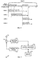
- an example of the mobile station 102 includes an antenna 710 that transmits signals to, and receives signals from, the base station 106a.
- a duplexer 712 provides a forward link channel or signal from the base station 106a to a receiver system 714.
- the receiver system 714 performs much of the demodulation and decoding of the receiver forward link channel. For example, the receiver system 714 performs Walsh code demodulation, and may perform power and signal quality measurements.
- a control processor 716 provides much of the processing of the forward link channel, as described below.
- a memory 718 permanently stores routines performed by the control processor 716, and provides a temporary storage of data such as received frames.
- a transmitter system 720 encodes, modulates, amplifies and up converts a reverse link traffic data signal for transmission back to the base station 106a.
- the base station 106a may transmit information to the mobile station that identifies for the mobile station the phase value provided by the phase rotator 206.
- the base station 106a may send phase value information to the mobile station 102 (1) when only pilot symbols are given a phase offset, (2) when multiple Walsh code channels are used for one user to carry high data rates, these channels are given different phase offsets, and when pilot symbols on these channels are coherently combined, and (3) when pilot symbols from different Walsh code channels are to be combined and used by the mobile station, and these code channels are given different phase offsets.
- the control processor 716 may then correct phase changes in received slots based on the previously transmitted phase value. Thus, if the phase value is 180° (i.e., -1), then the demodulator in the receiver system 714 of the mobile station 102 multiplies the code by -1 to correct the phase.
- the phase rotator 206 rather than generating a random string of plus and minus one values, the phase rotator 206 generates an ordered sequence of alternating plus and minus one values (i.e., 1, -1, 1, -1, 1,...) which are applied to the new users.
- This alternative embodiment, and those described herein, are similar to previously described embodiments; only the significant differences are described in detail.
- the orthogonal code generator 204 of the modulator 200 under this alternative embodiment then randomly assigns orthogonal codes to each new caller. As a result, the phase of orthogonal codes multiplied with pilot symbols remains random, so that random orthogonal codes in the Walsh matrix are inverted (i.e., multiplied by -1).
- an encoder 800 is similar to the encoder 200, but replaces the phase rotator 206 with a pilot chip decimator 806.
- the chip decimator 806 identifies pilot symbols and eliminates the common sign chip position in the orthogonal codes output from the orthogonal code generator 204 for pilot symbols.
- the chip decimator 806 eliminates the first chip position in such codes (eliminates the chips in column 0).
- the encoder 800 sends empty pilot symbols in the first Walsh chip position.
- orthogonal code generator 204 and chip decimator 806 are shown as separate blocks, these blocks can be combined to form a single orthogonal code generator that outputs orthogonal codes having the common sign chip position eliminated.
- the orthogonal code generator 204 can be a stored table lacking the common sign chip position for each code.
- the chip decimator 806 is unnecessary and can be eliminated.
- the mobile station 102 replaces the decimated chip in the received symbols in at least one of two ways.
- the mobile station 102 recognizes that, except for the first row, all Walsh codes sum to a value of zero when employing a 1/-1, as opposed to 1/0, notation.
- the mobile station 102 can determine a plus or minus one value by observing the sign of the Walsh demodulation.
- the user station 102 can reconstruct the first chip with the Walsh functions. For example, if all the transmitted Walsh functions would sum to 0 if fully sent, then the user station 102 sums all of the received Walsh functions (without the first chips) over all the Walsh chips. The negative of this sum is the value that the received signal would have had if the Walsh functions were fully transmitted.
- a first Walsh demodulation of all the received Walsh functions provides simultaneous equations for solving for the first Walsh chip amplitudes.
- the control processor 716 of the mobile station 102 analyzes a sum of the received chips to determine the value of the first chip position.
- the base station 106a transmits information to the mobile station 102, when initially establishing a new call, that reflects the value of the decimated chip. This method is substantially similar to that described above with respect to FIG. 7 .
- the chip decimator 806 is replaced by a common chip attenuator (not shown).
- the common chip attenuator attenuates the common sign chip position by a selected amount.
- the value of the selected amount is then transmitted, typically when a new call is set up, to the mobile station 102.
- the mobile station 102 then boosts or amplifies the common sign chip position by the selected amount to regain orthogonality.
- This alternative embodiment is a more general application of the first alternative embodiment described above with respect to FIG. 8 .
- pilot symbols are sent and effectively time multiplexed by the base station 106a for concurrent users. Not only does this third class of solutions reduce the peaked average amplitude problem, but also reduces the number of symbols transmitted to thereby reduce interference among transmitted channels.
- the various users look for pilot symbols at selected times. When users would not be looking for any pilot symbols, the base station 106a does not send any pilot symbols during such times (i.e., during such slots).
- each slot includes four pilot symbols 0-3, the base station 106a transmits all four pilot symbols 0-3 in the first four symbol positions 0-3 of a slot 0, as shown in FIG. 9 . While the pilot symbols 0-3 are shown in consecutive symbol positions of the slot, they need not be so positioned.
- User 1 looks for and retrieves the four pilot symbols 0-3 in the symbol positions 0-3. Slots of subsequent users are offset by a fixed number 0 through k of symbol positions. The offsets of slots for users should occur with a resolution equal to one symbol length so that symbol boundaries are aligned.
- User 2 is offset by two symbol positions, from user 1, while user 3 is offset by eight symbol positions from user 2 (ten symbol positions from user 1).
- User 2 looks for and retrieves two of its four pilot symbols in symbol positions 2 and 3 of slot 0. Knowing that user 2 is offset by two symbol positions from the beginning of the slot, the base station 106a inserts two pilot symbols in symbol positions 4 and 5, in which user 2 looks for and obtains such symbols.
- the mobile station 106a Knowing that user 3 is offset by ten symbol positions from the start of the slot, the mobile station 106a inserts the pilot symbols 0-3 in symbol positions 11-14. User 3 therefore looks in symbol positions 11-14 to obtain its pilot symbols. User 4 has the same offset as user 3. Therefore, the base station 106a need not send any additional pilot symbols; user 4 looks in the same symbol positions as user 3 for its pilot symbols.
- the base station 106a does not transmit any pilot symbols where it knows that its users are not looking for such pilot symbols. Therefore, as shown in FIG. 9 , the base station 106a does not transmit any pilot symbols in symbol positions 6-9. Thus, rather than transmitting four symbols for each of the four users in this example (for a total of 16 symbols), the base station 106a transmits only ten symbols for the four users. By sending fewer pilot symbols, the peak to average ratio noted above is reduced. Such a system is possible because the pilot symbols are substantially similar.
- the base station 106a under this second alternative embodiment may employ the same Walsh code for each user for pilot symbols. The base station 106a, however, encodes data to each user with a different Walsh code. The control processor 716 of the mobile station 102 switches between one Walsh code to demodulate the pilot symbols, and another Walsh code to demodulate data traffic.
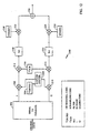
- an encoder 1000 for implementing this second alternative embodiment is similar to the encoder 200, but eliminates the phase rotator 206.
- the encoder 1000 includes the pilot symbol generator 1010 that provides pilot symbols to the channel data that is input to the serial to parallel converter 202.
- a base station processor 1012 identifies all users to which the encoder 1000 transmits and determines the symbol positions in each slot that the users will look for pilot symbols.
- the base station processor 1012 instructs the pilot symbol generator 1010 to only insert pilot symbols in the channel data when users are expected to receive such symbols. Data regarding users can be temporarily stored in a memory 1014.
- the base station processor 1012 instructs the pilot symbol generator 1010 to not output any pilot symbols in symbol positions that users are not expecting to retrieve such symbols. In sum, the base station processor 1012 determines in which symbol positions to send pilot symbols.
- the orthogonal code generator 204 then assigns and multiplies the same Walsh code for all pilot symbols.
- the base station processor 1012 instructs the orthogonal code generator 204 to generate multiple Walsh codes for pilot symbols.
- the base station processor 1012 also then causes the encoder 1000 to transmit information to the mobile station 102 so that the mobile station knows which Walsh codes were assigned to pilot symbols.
- a basic routine 1100 performed by the base station processor 1012 under this second alternative embodiment begins in step 1110 by identifying all current users to which the base station 106a transmits.
- the routine 1100 is preferably stored in the memory 1014.
- step 1112 the base station processor 1012 determines symbol positions in which each current user expects to find pilot symbols.
- step 1114 the base station processor 1012 provides signals to the pilot symbol generator 1010 to cause pilot symbols to be generated only in symbol positions where current users expect to find pilot symbols. This process may be repeated for each frame.
- an encoder 1200 is similar to the encoder 200, but replaces the phase rotator 206 with a random shift generator 1206.
- the random shift generator 1206 randomly shifts each orthogonal code output from the orthogonal code generator 204 by a random number between 0 and n, where n is the n th chip position of the orthogonal code.
- the random shift generator 1206 offsets each Walsh code by a random amount between 0 and 127.
- a first four and last six chip positions of a given Walsh code are 1-1-11..., 1-1-111-1, and the code were shifted rightward by one chip position, the resulting first and last four chip positions are -11-1-1..., -1-111. Note that the chip positions shifted from the right end of the code are positioned at the beginning, left end of the code.
- the random shift generator 1206 could be a pseudorandom number generator that randomly generates numbers 0 through 127 for the Walsh matrix of FIG. 3 .
- the orthogonal code generator 204 can be a stored table.
- the random shift generator 1206 and the orthogonal code generator 204 can be combined as a single circuit that generates orthogonal codes randomly offset by numbers equal to a number of chip positions for the orthogonal code.
- the base station 106a transmits not only the shift value for the channel of the mobile station 102, but the shift codes for all users to which the base station transmits. While requiring significant processor overhead for the control processor 716, the mobile station 102 unshifts all channels to regain orthogonality. Thereafter, the mobile station 102 may demodulate and decode its channel.
- teachings provided herein of the invention can be applied to other communication systems, not necessarily the exemplary communication system described above.
- the present invention has been generally described above as being employed in the CDMA communication system 100, the present invention is equally applicable to other digital or analog cellular communication systems.
- the base station 106a is described above as altering the orthogonal codes or selectively transmitting pilot symbols, such techniques can be applied to a user station.
Claims (10)
- Ein Verfahren zum Reduzieren von Übertragungs- bzw. Sendesignalleistung oder Interferenz von gesendeten Kommunikationssignalen und zwar geeignet zur Nutzung in einem Kommunikationssystem, das eine Basisstation und eine Vielzahl von Nutzerstationen besitzt, die Kommunikationssignale mit der Basisstation austauschen, wobei das Verfahren Folgendes aufweist:Empfangen von Kanaldaten zur Übertragung auf einer Vielzahl von Kanälen an die Vielzahl von Nutzerstationen, wobei die Kanaldaten Pilotsymboldaten beinhalten;Bestimmen von Symbolpositionen in denen jede von der Vielzahl von Nutzerstationen erwartet, Pilotsymbole zu finden; undSenden an die Vielzahl von Nutzerstationen Pilotsymbole nur in Symbolpositionen, an denen die Vielzahl von Nutzerstationen erwarten Pilotsymbole zu finden, und nicht Senden von Pilotsymbolen in anderen Symbolpositionen, gekennzeichnet dadurch, dass das Senden an die Vielzahl von Nutzerstationen ferner Folgendes aufweist:zeitliches Verschieben von Schlitzen für wenigstens einige von der Vielzahl von Kanälen, wobei jeder Kanal Symbolpositionen für Pilotsymbole beinhaltet; undSenden von nur einem Satz von Pilotsymbolen für Schlitze die gleichzeitig in wenigstens zwei unterschiedlichen Kanälen auftreten.
- Verfahren nach Anspruch 1, das ferner aufweist Codieren der Pilotsymbole für jede von der Vielzahl von Nutzerstationen mit einem orthogonalen Code basierend auf einem Versatz von einem Referenzschlitz.
- Verfahren nach Anspruch 1, ferner aufweisend Codieren der Pilotsymbole für die Vielzahl von Nutzerstationen mit einem gemeinsamen orthogonalen Code.
- Eine Vorrichtung zum Reduzieren von Übertragungs- bzw. Sendesignalleistung oder Interferenz von gesendeten Kommunikationssignalen, geeignet zur Nutzung in einem Kommunikationssystem, das eine Basisstation (106) und eine Vielzahl von Nutzerstationen, die Kommunikationssignale mit der Basisstation austauschen, besitzt, wobei die Vorrichtung Folgendes aufweist:Mittel zum Empfangen (202) von Kanaldaten zur Übertragung auf einer Vielzahl von Kanälen an die Vielzahl von Nutzerstationen, wobei die Kanaldaten Pilotsymboldaten beinhalten;Mittel zum Bestimmen von Symbolpositionen in denen jede von der Vielzahl von Nutzerstationen erwartet Pilotsymbole zu finden; undMittel zum Senden (106) an die Vielzahl von Nutzerstationen von Pilotsymbolen nur in Symbolpositionen, an denen die Vielzahl von Nutzerstationen erwartet, Pilotsymbole zu finden und nicht Senden von Pilotsymbolen in anderen Symbolpositionen, gekennzeichnet dadurch, dass die Mittel zum Senden an die Vielzahl von Nutzerstationen Folgendes aufweisen:Mittel zum zeitlichen Verschieben von Schlitzen für wenigstens einige von der Vielzahl von Kanälen, wobei jeder Kanal Symbolpositionen für Pilotsymbole beinhaltet; undMittel zum Senden (106) von nur einem Satz von Pilotsymbolen für Schlitze, die gleichzeitig in wenigstens zwei unterschiedlichen Kanälen auftreten.
- Vorrichtung nach Anspruch 4, die ferner Mittel zum Codieren (204) der Pilotsymbole für jede von der Vielzahl von Nutzerstationen mit einem orthogonalen Code basierend auf einem Versatz von einem Referenzschlitz, aufweist.
- Vorrichtung nach Anspruch 4, die ferner Mittel zum Codieren (204) der Pilotsymbole für die Vielzahl von Nutzerstationen mit einem gemeinsamen orthogonalen Code aufweist.
- Vorrichtung nach Anspruch 4, wobei die Mittel zum Empfangen (202) Folgendes aufweisen:einen Eingangsknoten, der Daten empfängt zur Übertragung auf einer Vielzahl von Kanälen an die Vielzahl von Nutzerstationen; unddie Mittel zum Bestimmen Folgendes aufweisen:einen Pilotsymbolgenerator, gekoppelt an den Eingangsknoten, der Pilotsymbole erzeugt; undeinen Prozessor gekoppelt an den Pilotsymbolgenerator, der Symbolpositionen bestimmt in denen jede von der Vielzahl von Nutzerstationen erwartet Pilotsymbole zu finden und der den Pilotsymbolgenerator anweist, Pilotsymbole für die Vielzahl von Nutzerstationen nur in Symbolpositionen zu erzeugen, an denen die Vielzahl von Nutzerstationen erwartet, Pilotsymbole zu finden.
- Vorrichtung nach Anspruch 7, wobei der Prozessor Schlitze zeitlich verschiebt für wenigstens einige von der Vielzahl von Kanälen, wobei jeder Kanal Symbolpositionen für Pilotsymbole beinhaltet und bewirkt, dass nur ein Satz von Pilotsymbolen für Schlitze gesendet wird, die gleichzeitig in wenigstens zwei unterschiedlichen Kanälen auftreten.
- Vorrichtung nach Anspruch 7, die ferner einen Codierer aufweist, der an den Pilotsymbolgenerator gekoppelt ist, der die Pilotsymbole codiert für jede von der Vielzahl von Nutzerstationen mit einem orthogonalen Code, basierend auf einem Versatz von einem Referenzschlitz.
- Vorrichtung nach Anspruch 7, die ferner einen Codierer aufweist, der an den Pilotsymbolgenerator gekoppelt ist, der die Pilotsymbole für die Vielzahl von Nutzerstationen mit einem gemeinsamen orthogonalen Code codiert.
Applications Claiming Priority (2)
| Application Number | Priority Date | Filing Date | Title |
|---|---|---|---|
| US09/144,402 US6310869B1 (en) | 1998-08-31 | 1998-08-31 | Method and apparatus for reducing amplitude variations and interference in communication signals, such as in wireless communication signals employing inserted pilot symbols |
| EP99942536A EP1110360B1 (de) | 1998-08-31 | 1999-08-30 | Verfahren und vorrichtung zur verminderung von amplitudenschwankungen in kommunikationssignalen unter verwendung von eingesetzten pilotsymbolen |
Related Parent Applications (1)
| Application Number | Title | Priority Date | Filing Date |
|---|---|---|---|
| EP99942536A Division EP1110360B1 (de) | 1998-08-31 | 1999-08-30 | Verfahren und vorrichtung zur verminderung von amplitudenschwankungen in kommunikationssignalen unter verwendung von eingesetzten pilotsymbolen |
Publications (2)
| Publication Number | Publication Date |
|---|---|
| EP1613013A1 EP1613013A1 (de) | 2006-01-04 |
| EP1613013B1 true EP1613013B1 (de) | 2008-07-09 |
Family
ID=22508421
Family Applications (2)
| Application Number | Title | Priority Date | Filing Date |
|---|---|---|---|
| EP05018036A Expired - Lifetime EP1613013B1 (de) | 1998-08-31 | 1999-08-30 | Verfahren und Vorrichtung zur Verminderung von Amplitudenschwankungen und Störungen in Kommunikationssignalen mit eingesetzten Pilotsymbolen |
| EP99942536A Expired - Lifetime EP1110360B1 (de) | 1998-08-31 | 1999-08-30 | Verfahren und vorrichtung zur verminderung von amplitudenschwankungen in kommunikationssignalen unter verwendung von eingesetzten pilotsymbolen |
Family Applications After (1)
| Application Number | Title | Priority Date | Filing Date |
|---|---|---|---|
| EP99942536A Expired - Lifetime EP1110360B1 (de) | 1998-08-31 | 1999-08-30 | Verfahren und vorrichtung zur verminderung von amplitudenschwankungen in kommunikationssignalen unter verwendung von eingesetzten pilotsymbolen |
Country Status (12)
| Country | Link |
|---|---|
| US (2) | US6310869B1 (de) |
| EP (2) | EP1613013B1 (de) |
| JP (1) | JP4191388B2 (de) |
| KR (1) | KR100697510B1 (de) |
| CN (1) | CN1186888C (de) |
| AR (1) | AR022371A1 (de) |
| AT (2) | ATE309662T1 (de) |
| AU (1) | AU5589299A (de) |
| DE (2) | DE69928269T2 (de) |
| ES (1) | ES2251221T3 (de) |
| HK (1) | HK1040014B (de) |
| WO (1) | WO2000013337A2 (de) |
Families Citing this family (65)
| Publication number | Priority date | Publication date | Assignee | Title |
|---|---|---|---|---|
| US6603751B1 (en) * | 1998-02-13 | 2003-08-05 | Qualcomm Incorporated | Method and system for performing a handoff in a wireless communication system, such as a hard handoff |
| US20030194033A1 (en) | 1998-05-21 | 2003-10-16 | Tiedemann Edward G. | Method and apparatus for coordinating transmission of short messages with hard handoff searches in a wireless communications system |
| WO2000007377A2 (en) * | 1998-07-28 | 2000-02-10 | Samsung Electronics Co., Ltd. | Gated transmission in control hold state in cdma communication system |
| US6396817B2 (en) * | 1998-08-31 | 2002-05-28 | Qualcomm Incorporated | Signal splitting method for limiting peak power in a CDMA system |
| ES2397266T3 (es) | 1998-12-14 | 2013-03-05 | Interdigital Technology Corporation | Detección de preámbulo de canal de acceso aleatorio |
| US6721349B1 (en) * | 1999-01-28 | 2004-04-13 | Qualcomm Incorporated | Method and apparatus for reducing peak-to-average ratio in a CDMA communication system |
| US6587446B2 (en) | 1999-02-11 | 2003-07-01 | Qualcomm Incorporated | Handoff in a wireless communication system |
| US6549564B1 (en) * | 1999-04-08 | 2003-04-15 | Telefonaktiebolaget Lm Ericsson (Publ) | Random access in a mobile telecommunications system |
| US6674810B1 (en) * | 1999-05-27 | 2004-01-06 | 3Com Corporation | Method and apparatus for reducing peak-to-average power ratio in a discrete multi-tone signal |
| US6961369B1 (en) | 1999-11-09 | 2005-11-01 | Aware, Inc. | System and method for scrambling the phase of the carriers in a multicarrier communications system |
| EP1195917B1 (de) * | 2000-08-02 | 2004-02-25 | Lucent Technologies Inc. | Verfahren zur Verringerung des Verhältnisses zwischen Spitzen- und mittlerer Leistung in einem drahtlosen Kommunikationssystem |
| US20020118783A1 (en) * | 2001-02-26 | 2002-08-29 | Peter Cripps | Smart antenna based spectrum multiplexing using a pilot signal |
| US6836666B2 (en) * | 2001-05-08 | 2004-12-28 | Lucent Technologies Inc. | Method to control uplink transmissions in a wireless communication system |
| WO2002099999A1 (en) * | 2001-05-31 | 2002-12-12 | Magn0Lia Broadband, Inc. | Communication device with smart antenna using a quality-indication signal |
| US8249187B2 (en) | 2002-05-09 | 2012-08-21 | Google Inc. | System, method and apparatus for mobile transmit diversity using symmetric phase difference |
| US7190749B2 (en) * | 2001-06-06 | 2007-03-13 | Qualcomm Incorporated | Method and apparatus for canceling pilot interference in a wireless communication system |
| US7106784B2 (en) * | 2002-01-25 | 2006-09-12 | Sasken Communication Technologies Limited | Universal rake receiver |
| US7292552B2 (en) * | 2002-03-14 | 2007-11-06 | Qualcomm Incorporated | Method and apparatus for reducing interference in a wireless communication system |
| US7266156B2 (en) | 2002-04-26 | 2007-09-04 | Qualcomm Incorporated | Method and apparatus for reducing peak to average power ratio of a multi-carrier signal |
| KR100452512B1 (ko) * | 2002-08-16 | 2004-10-13 | 엘지전자 주식회사 | 채널용량 개선 왈쉬코드 확산장치 및 그 운용방법 |
| KR100475180B1 (ko) * | 2002-10-24 | 2005-03-10 | 엘지전자 주식회사 | 멀티캐리어 송신기용 피에이알(par)감소장치 |
| US6996763B2 (en) * | 2003-01-10 | 2006-02-07 | Qualcomm Incorporated | Operation of a forward link acknowledgement channel for the reverse link data |
| US8150407B2 (en) * | 2003-02-18 | 2012-04-03 | Qualcomm Incorporated | System and method for scheduling transmissions in a wireless communication system |
| US7155236B2 (en) | 2003-02-18 | 2006-12-26 | Qualcomm Incorporated | Scheduled and autonomous transmission and acknowledgement |
| US7660282B2 (en) * | 2003-02-18 | 2010-02-09 | Qualcomm Incorporated | Congestion control in a wireless data network |
| US8081598B2 (en) * | 2003-02-18 | 2011-12-20 | Qualcomm Incorporated | Outer-loop power control for wireless communication systems |
| US20040160922A1 (en) * | 2003-02-18 | 2004-08-19 | Sanjiv Nanda | Method and apparatus for controlling data rate of a reverse link in a communication system |
| US7418064B2 (en) * | 2003-02-18 | 2008-08-26 | Qualcomm, Incorporated | Systems and methods for hierarchically demodulating and decoding a data signal using a pilot signal and an additional signal |
| US8391249B2 (en) | 2003-02-18 | 2013-03-05 | Qualcomm Incorporated | Code division multiplexing commands on a code division multiplexed channel |
| US8023950B2 (en) | 2003-02-18 | 2011-09-20 | Qualcomm Incorporated | Systems and methods for using selectable frame durations in a wireless communication system |
| US7215930B2 (en) * | 2003-03-06 | 2007-05-08 | Qualcomm, Incorporated | Method and apparatus for providing uplink signal-to-noise ratio (SNR) estimation in a wireless communication |
| US8705588B2 (en) | 2003-03-06 | 2014-04-22 | Qualcomm Incorporated | Systems and methods for using code space in spread-spectrum communications |
| US8477592B2 (en) * | 2003-05-14 | 2013-07-02 | Qualcomm Incorporated | Interference and noise estimation in an OFDM system |
| KR20050012478A (ko) * | 2003-07-25 | 2005-02-02 | 유티스타콤코리아 유한회사 | Cdma-2000 시스템에서의 왈시 코드 배정을 이용한papr 제어 방법 |
| US8489949B2 (en) | 2003-08-05 | 2013-07-16 | Qualcomm Incorporated | Combining grant, acknowledgement, and rate control commands |
| CN1833390B (zh) * | 2003-08-07 | 2012-01-18 | 松下电器产业株式会社 | 无线发送装置及无线发送方法 |
| DE10337828A1 (de) * | 2003-08-18 | 2005-04-21 | Siemens Ag | Verfahren zur Auswahl eines Übertragungskanals |
| US20050141410A1 (en) * | 2003-10-30 | 2005-06-30 | 1021 Technologies Inc. | Method of reducing peak-to-average ratio in multi-carrier communications systems |
| US7551637B2 (en) * | 2004-01-23 | 2009-06-23 | Qualcomm Incorporated | Method and apparatus for channel sensitive scheduling in a communication system |
| US7272359B2 (en) * | 2004-01-26 | 2007-09-18 | Magnolia Broadband Inc. | Communicating signals according to a quality indicator using multiple antenna elements |
| US9094144B2 (en) * | 2004-04-29 | 2015-07-28 | Alcatel Lucent | Methods and apparatus for code division multiple access communication using code book that provides reduced peak-to-average power ratio |
| US20060098679A1 (en) * | 2004-11-10 | 2006-05-11 | Telefonaktiebolaget Lm Ericsson | Method and apparatus for reducing peak power in code multiplexed downlink control channels |
| JP4546342B2 (ja) | 2005-07-07 | 2010-09-15 | パナソニック株式会社 | 送信装置および送信方法 |
| US7917798B2 (en) | 2005-10-04 | 2011-03-29 | Hypres, Inc. | Superconducting digital phase rotator |
| JP4771835B2 (ja) * | 2006-03-06 | 2011-09-14 | 株式会社リコー | トナー及び画像形成方法 |
| US7991040B2 (en) | 2006-04-04 | 2011-08-02 | Qualcomm Incorporated | Methods and apparatus for reduction of a peak to average ratio for an OFDM transmit signal |
| GB0623481D0 (en) * | 2006-11-24 | 2007-01-03 | Imp Innovations Ltd | Improved methods and apparatus for transmitting and receiving data |
| KR101422014B1 (ko) * | 2007-05-10 | 2014-07-23 | 엘지전자 주식회사 | 기본 코드 반복 방식에 의한 긴 코드 생성 방법 및 이를이용한 제어 정보 전송 방법 |
| US7773664B2 (en) * | 2008-03-18 | 2010-08-10 | On-Ramp Wireless, Inc. | Random phase multiple access system with meshing |
| US20090239550A1 (en) * | 2008-03-18 | 2009-09-24 | Myers Theodore J | Random phase multiple access system with location tracking |
| US8520721B2 (en) | 2008-03-18 | 2013-08-27 | On-Ramp Wireless, Inc. | RSSI measurement mechanism in the presence of pulsed jammers |
| US7733945B2 (en) * | 2008-03-18 | 2010-06-08 | On-Ramp Wireless, Inc. | Spread spectrum with doppler optimization |
| US20100195553A1 (en) * | 2008-03-18 | 2010-08-05 | Myers Theodore J | Controlling power in a spread spectrum system |
| US7526013B1 (en) * | 2008-03-18 | 2009-04-28 | On-Ramp Wireless, Inc. | Tag communications with access point |
| US8477830B2 (en) | 2008-03-18 | 2013-07-02 | On-Ramp Wireless, Inc. | Light monitoring system using a random phase multiple access system |
| US8958460B2 (en) | 2008-03-18 | 2015-02-17 | On-Ramp Wireless, Inc. | Forward error correction media access control system |
| US8644407B2 (en) * | 2008-06-23 | 2014-02-04 | Blackberry Limited | Apparatus, and associated method of phase-offset modulation, for space-time coded wireless communication systems |
| US8964692B2 (en) * | 2008-11-10 | 2015-02-24 | Qualcomm Incorporated | Spectrum sensing of bluetooth using a sequence of energy detection measurements |
| WO2010073339A1 (ja) * | 2008-12-25 | 2010-07-01 | 富士通株式会社 | 信号生成装置、送信装置、信号生成方法、送信方法および通信システム |
| EP2404468B1 (de) * | 2009-03-03 | 2012-12-19 | Telefonaktiebolaget L M Ericsson (PUBL) | Basisstation und verfahren zur scheduler-gesteuerten einstellung der ausgangsleistung eines basisstations-leistungsverstärkers |
| US8363699B2 (en) | 2009-03-20 | 2013-01-29 | On-Ramp Wireless, Inc. | Random timing offset determination |
| KR20140075252A (ko) * | 2012-12-11 | 2014-06-19 | 한국전자통신연구원 | 제어 채널 구성, 제어 정보 검출 장치 및 방법 |
| US9664767B2 (en) * | 2013-05-17 | 2017-05-30 | Massachusetts Institute Of Technology | Time-resolved magnetic sensing with electronic spins in diamond |
| KR101403221B1 (ko) * | 2013-06-05 | 2014-06-02 | 이화여자대학교 산학협력단 | 스마트 그리드 환경에서 링 통신 구조와 수직코드를 사용한 유틸리티 사용량 측정 시스템 및 방법 |
| US9621197B2 (en) * | 2015-03-10 | 2017-04-11 | Samsung Electronics Co., Ltd. | Bi-phased on-off keying (OOK) transmitter and communication method |
Family Cites Families (13)
| Publication number | Priority date | Publication date | Assignee | Title |
|---|---|---|---|---|
| US4901307A (en) | 1986-10-17 | 1990-02-13 | Qualcomm, Inc. | Spread spectrum multiple access communication system using satellite or terrestrial repeaters |
| US5109390A (en) | 1989-11-07 | 1992-04-28 | Qualcomm Incorporated | Diversity receiver in a cdma cellular telephone system |
| US5101501A (en) | 1989-11-07 | 1992-03-31 | Qualcomm Incorporated | Method and system for providing a soft handoff in communications in a cdma cellular telephone system |
| US5056109A (en) | 1989-11-07 | 1991-10-08 | Qualcomm, Inc. | Method and apparatus for controlling transmission power in a cdma cellular mobile telephone system |
| US5103459B1 (en) | 1990-06-25 | 1999-07-06 | Qualcomm Inc | System and method for generating signal waveforms in a cdma cellular telephone system |
| US5497395A (en) * | 1994-04-04 | 1996-03-05 | Qualcomm Incorporated | Method and apparatus for modulating signal waveforms in a CDMA communication system |
| JP3126904B2 (ja) | 1994-07-21 | 2001-01-22 | キヤノン株式会社 | スペクトラム拡散通信装置 |
| US5602833A (en) | 1994-12-19 | 1997-02-11 | Qualcomm Incorporated | Method and apparatus for using Walsh shift keying in a spread spectrum communication system |
| KR100220344B1 (ko) * | 1995-02-23 | 1999-09-15 | 다치카와 게이지 | 가변 속도 전송 방법 및 그 방법을 이용한 송신기 및 수신기 |
| US5793797A (en) | 1995-05-09 | 1998-08-11 | Unisys Corporation | Data transmisson system with a low peak-to-average power ratio based on distorting small amplitude signals |
| US5742595A (en) | 1995-06-02 | 1998-04-21 | Dsc Communications Corporation | Processing CDMA signals |
| RU99110385A (ru) | 1996-10-18 | 2001-03-10 | Телефонактиеболагет ЛМ Эрикссон (пабл) (SE) | Способ смещения синхронизации передачи для мобильных телефонных систем пп-мдкр |
| JPH10190626A (ja) | 1996-12-27 | 1998-07-21 | Matsushita Electric Ind Co Ltd | Cdma受信装置 |
-
1998
- 1998-08-31 US US09/144,402 patent/US6310869B1/en not_active Expired - Lifetime
-
1999
- 1999-08-30 AT AT99942536T patent/ATE309662T1/de not_active IP Right Cessation
- 1999-08-30 DE DE69928269T patent/DE69928269T2/de not_active Expired - Lifetime
- 1999-08-30 ES ES99942536T patent/ES2251221T3/es not_active Expired - Lifetime
- 1999-08-30 AR ARP990104340A patent/AR022371A1/es unknown
- 1999-08-30 EP EP05018036A patent/EP1613013B1/de not_active Expired - Lifetime
- 1999-08-30 WO PCT/US1999/019734 patent/WO2000013337A2/en active IP Right Grant
- 1999-08-30 DE DE69939078T patent/DE69939078D1/de not_active Expired - Lifetime
- 1999-08-30 EP EP99942536A patent/EP1110360B1/de not_active Expired - Lifetime
- 1999-08-30 JP JP2000568202A patent/JP4191388B2/ja not_active Expired - Lifetime
- 1999-08-30 CN CNB998128392A patent/CN1186888C/zh not_active Expired - Lifetime
- 1999-08-30 AU AU55892/99A patent/AU5589299A/en not_active Abandoned
- 1999-08-30 KR KR1020017002707A patent/KR100697510B1/ko not_active IP Right Cessation
- 1999-08-30 AT AT05018036T patent/ATE400956T1/de not_active IP Right Cessation
-
2001
- 2001-09-07 US US09/949,215 patent/US20020021683A1/en not_active Abandoned
-
2002
- 2002-02-20 HK HK02101229.9A patent/HK1040014B/zh not_active IP Right Cessation
Also Published As
| Publication number | Publication date |
|---|---|
| CN1186888C (zh) | 2005-01-26 |
| ATE309662T1 (de) | 2005-11-15 |
| EP1110360A2 (de) | 2001-06-27 |
| US6310869B1 (en) | 2001-10-30 |
| JP4191388B2 (ja) | 2008-12-03 |
| AU5589299A (en) | 2000-03-21 |
| HK1040014A1 (en) | 2002-05-17 |
| DE69939078D1 (de) | 2008-08-21 |
| KR20010074910A (ko) | 2001-08-09 |
| ES2251221T3 (es) | 2006-04-16 |
| DE69928269T2 (de) | 2006-07-13 |
| HK1040014B (zh) | 2005-08-05 |
| US20020021683A1 (en) | 2002-02-21 |
| WO2000013337A2 (en) | 2000-03-09 |
| ATE400956T1 (de) | 2008-07-15 |
| DE69928269D1 (de) | 2005-12-15 |
| AR022371A1 (es) | 2002-09-04 |
| JP2002524911A (ja) | 2002-08-06 |
| CN1325583A (zh) | 2001-12-05 |
| EP1110360B1 (de) | 2005-11-09 |
| WO2000013337A3 (en) | 2000-06-08 |
| KR100697510B1 (ko) | 2007-03-20 |
| EP1613013A1 (de) | 2006-01-04 |
Similar Documents
| Publication | Publication Date | Title |
|---|---|---|
| EP1613013B1 (de) | Verfahren und Vorrichtung zur Verminderung von Amplitudenschwankungen und Störungen in Kommunikationssignalen mit eingesetzten Pilotsymbolen | |
| US5930230A (en) | High data rate CDMA wireless communication system | |
| US5926500A (en) | Reduced peak-to-average transmit power high data rate CDMA wireless communication system | |
| CN100592649C (zh) | 在无线通信系统中使用的用户单元和方法 | |
| KR20000024783A (ko) | 다중 반송파 부호분할다중접속방식의 기지국 시스템, 그의 다중코드 파형 발생방법 및 이를 이용한 이동통신 시스템 | |
| EP0978179B1 (de) | Schnelle Datenübertragung unter Verwendung einer mehrzahl von langsameren Kanälen | |
| US6996080B1 (en) | Chip-synchronous CDMA multiplexer and method resulting in constant envelope signals | |
| EP0990313B1 (de) | Mehrkanalverbindung mit reduzierter spitzen- zu durchschnittamplitude |
Legal Events
| Date | Code | Title | Description |
|---|---|---|---|
| PUAI | Public reference made under article 153(3) epc to a published international application that has entered the european phase |
Free format text: ORIGINAL CODE: 0009012 |
|
| 17P | Request for examination filed |
Effective date: 20050819 |
|
| AC | Divisional application: reference to earlier application |
Ref document number: 1110360 Country of ref document: EP Kind code of ref document: P |
|
| AK | Designated contracting states |
Kind code of ref document: A1 Designated state(s): AT BE CH CY DE DK ES FI FR GB GR IE IT LI LU MC NL PT SE |
|
| AX | Request for extension of the european patent |
Extension state: AL LT LV MK RO SI |
|
| RIN1 | Information on inventor provided before grant (corrected) |
Inventor name: RAZOUMOV, LEONID Inventor name: HOLTZMAN, JACK Inventor name: TERASAWA, DAISUKE |
|
| AKX | Designation fees paid |
Designated state(s): AT BE CH CY DE DK ES FI FR GB GR IE IT LI LU MC NL PT SE |
|
| REG | Reference to a national code |
Ref country code: HK Ref legal event code: DE Ref document number: 1086961 Country of ref document: HK |
|
| GRAP | Despatch of communication of intention to grant a patent |
Free format text: ORIGINAL CODE: EPIDOSNIGR1 |
|
| RTI1 | Title (correction) |
Free format text: METHOD AND APPARATUS FOR REDUCING AMPLITUDE VARIATIONS AND INTERFERENCE IN COMMUNICATION SIGNALS EMPLOYING INSERTED PILOT SIGNALS |
|
| RAP1 | Party data changed (applicant data changed or rights of an application transferred) |
Owner name: QUALCOMM INCORPORATED |
|
| GRAS | Grant fee paid |
Free format text: ORIGINAL CODE: EPIDOSNIGR3 |
|
| GRAA | (expected) grant |
Free format text: ORIGINAL CODE: 0009210 |
|
| AC | Divisional application: reference to earlier application |
Ref document number: 1110360 Country of ref document: EP Kind code of ref document: P |
|
| AK | Designated contracting states |
Kind code of ref document: B1 Designated state(s): AT BE CH CY DE DK ES FI FR GB GR IE IT LI LU MC NL PT SE |
|
| REG | Reference to a national code |
Ref country code: GB Ref legal event code: FG4D |
|
| REG | Reference to a national code |
Ref country code: CH Ref legal event code: EP |
|
| REF | Corresponds to: |
Ref document number: 69939078 Country of ref document: DE Date of ref document: 20080821 Kind code of ref document: P |
|
| REG | Reference to a national code |
Ref country code: IE Ref legal event code: FG4D |
|
| REG | Reference to a national code |
Ref country code: CH Ref legal event code: NV Representative=s name: R. A. EGLI & CO. PATENTANWAELTE |
|
| REG | Reference to a national code |
Ref country code: SE Ref legal event code: TRGR |
|
| PG25 | Lapsed in a contracting state [announced via postgrant information from national office to epo] |
Ref country code: PT Free format text: LAPSE BECAUSE OF FAILURE TO SUBMIT A TRANSLATION OF THE DESCRIPTION OR TO PAY THE FEE WITHIN THE PRESCRIBED TIME-LIMIT Effective date: 20081209 Ref country code: ES Free format text: LAPSE BECAUSE OF FAILURE TO SUBMIT A TRANSLATION OF THE DESCRIPTION OR TO PAY THE FEE WITHIN THE PRESCRIBED TIME-LIMIT Effective date: 20081020 |
|
| PG25 | Lapsed in a contracting state [announced via postgrant information from national office to epo] |
Ref country code: AT Free format text: LAPSE BECAUSE OF FAILURE TO SUBMIT A TRANSLATION OF THE DESCRIPTION OR TO PAY THE FEE WITHIN THE PRESCRIBED TIME-LIMIT Effective date: 20080709 |
|
| PG25 | Lapsed in a contracting state [announced via postgrant information from national office to epo] |
Ref country code: BE Free format text: LAPSE BECAUSE OF FAILURE TO SUBMIT A TRANSLATION OF THE DESCRIPTION OR TO PAY THE FEE WITHIN THE PRESCRIBED TIME-LIMIT Effective date: 20080709 Ref country code: MC Free format text: LAPSE BECAUSE OF NON-PAYMENT OF DUE FEES Effective date: 20080831 |
|
| PG25 | Lapsed in a contracting state [announced via postgrant information from national office to epo] |
Ref country code: DK Free format text: LAPSE BECAUSE OF FAILURE TO SUBMIT A TRANSLATION OF THE DESCRIPTION OR TO PAY THE FEE WITHIN THE PRESCRIBED TIME-LIMIT Effective date: 20080709 |
|
| PLBE | No opposition filed within time limit |
Free format text: ORIGINAL CODE: 0009261 |
|
| STAA | Information on the status of an ep patent application or granted ep patent |
Free format text: STATUS: NO OPPOSITION FILED WITHIN TIME LIMIT |
|
| 26N | No opposition filed |
Effective date: 20090414 |
|
| PG25 | Lapsed in a contracting state [announced via postgrant information from national office to epo] |
Ref country code: LU Free format text: LAPSE BECAUSE OF NON-PAYMENT OF DUE FEES Effective date: 20080830 Ref country code: CY Free format text: LAPSE BECAUSE OF FAILURE TO SUBMIT A TRANSLATION OF THE DESCRIPTION OR TO PAY THE FEE WITHIN THE PRESCRIBED TIME-LIMIT Effective date: 20080709 |
|
| PG25 | Lapsed in a contracting state [announced via postgrant information from national office to epo] |
Ref country code: GR Free format text: LAPSE BECAUSE OF FAILURE TO SUBMIT A TRANSLATION OF THE DESCRIPTION OR TO PAY THE FEE WITHIN THE PRESCRIBED TIME-LIMIT Effective date: 20081010 |
|
| PGFP | Annual fee paid to national office [announced via postgrant information from national office to epo] |
Ref country code: IE Payment date: 20100709 Year of fee payment: 12 Ref country code: CH Payment date: 20100726 Year of fee payment: 12 |
|
| PGFP | Annual fee paid to national office [announced via postgrant information from national office to epo] |
Ref country code: SE Payment date: 20100809 Year of fee payment: 12 Ref country code: FI Payment date: 20100812 Year of fee payment: 12 |
|
| REG | Reference to a national code |
Ref country code: NL Ref legal event code: V1 Effective date: 20120301 |
|
| REG | Reference to a national code |
Ref country code: CH Ref legal event code: PL |
|
| REG | Reference to a national code |
Ref country code: SE Ref legal event code: EUG |
|
| PG25 | Lapsed in a contracting state [announced via postgrant information from national office to epo] |
Ref country code: CH Free format text: LAPSE BECAUSE OF NON-PAYMENT OF DUE FEES Effective date: 20110831 Ref country code: LI Free format text: LAPSE BECAUSE OF NON-PAYMENT OF DUE FEES Effective date: 20110831 |
|
| REG | Reference to a national code |
Ref country code: IE Ref legal event code: MM4A |
|
| PG25 | Lapsed in a contracting state [announced via postgrant information from national office to epo] |
Ref country code: FI Free format text: LAPSE BECAUSE OF NON-PAYMENT OF DUE FEES Effective date: 20110830 Ref country code: NL Free format text: LAPSE BECAUSE OF NON-PAYMENT OF DUE FEES Effective date: 20120301 |
|
| PG25 | Lapsed in a contracting state [announced via postgrant information from national office to epo] |
Ref country code: IE Free format text: LAPSE BECAUSE OF NON-PAYMENT OF DUE FEES Effective date: 20110830 |
|
| REG | Reference to a national code |
Ref country code: HK Ref legal event code: WD Ref document number: 1086961 Country of ref document: HK |
|
| PG25 | Lapsed in a contracting state [announced via postgrant information from national office to epo] |
Ref country code: SE Free format text: LAPSE BECAUSE OF NON-PAYMENT OF DUE FEES Effective date: 20110831 |
|
| PGFP | Annual fee paid to national office [announced via postgrant information from national office to epo] |
Ref country code: NL Payment date: 20100831 Year of fee payment: 12 |
|
| REG | Reference to a national code |
Ref country code: FR Ref legal event code: PLFP Year of fee payment: 18 |
|
| REG | Reference to a national code |
Ref country code: FR Ref legal event code: PLFP Year of fee payment: 19 |
|
| REG | Reference to a national code |
Ref country code: FR Ref legal event code: PLFP Year of fee payment: 20 |
|
| PGFP | Annual fee paid to national office [announced via postgrant information from national office to epo] |
Ref country code: FR Payment date: 20180718 Year of fee payment: 20 Ref country code: IT Payment date: 20180813 Year of fee payment: 20 Ref country code: DE Payment date: 20180716 Year of fee payment: 20 |
|
| PGFP | Annual fee paid to national office [announced via postgrant information from national office to epo] |
Ref country code: GB Payment date: 20180726 Year of fee payment: 20 |
|
| REG | Reference to a national code |
Ref country code: DE Ref legal event code: R071 Ref document number: 69939078 Country of ref document: DE |
|
| REG | Reference to a national code |
Ref country code: GB Ref legal event code: PE20 Expiry date: 20190829 |
|
| PG25 | Lapsed in a contracting state [announced via postgrant information from national office to epo] |
Ref country code: GB Free format text: LAPSE BECAUSE OF EXPIRATION OF PROTECTION Effective date: 20190829 |