EP1612880B1 - Waveguide branching filter/polarizer - Google Patents
Waveguide branching filter/polarizer Download PDFInfo
- Publication number
- EP1612880B1 EP1612880B1 EP04725537A EP04725537A EP1612880B1 EP 1612880 B1 EP1612880 B1 EP 1612880B1 EP 04725537 A EP04725537 A EP 04725537A EP 04725537 A EP04725537 A EP 04725537A EP 1612880 B1 EP1612880 B1 EP 1612880B1
- Authority
- EP
- European Patent Office
- Prior art keywords
- electric wave
- wave
- waveguide
- conducting
- polarized
- Prior art date
- Legal status (The legal status is an assumption and is not a legal conclusion. Google has not performed a legal analysis and makes no representation as to the accuracy of the status listed.)
- Expired - Fee Related
Links
Images


Classifications
-
- H—ELECTRICITY
- H01—ELECTRIC ELEMENTS
- H01P—WAVEGUIDES; RESONATORS, LINES, OR OTHER DEVICES OF THE WAVEGUIDE TYPE
- H01P1/00—Auxiliary devices
- H01P1/16—Auxiliary devices for mode selection, e.g. mode suppression or mode promotion; for mode conversion
- H01P1/161—Auxiliary devices for mode selection, e.g. mode suppression or mode promotion; for mode conversion sustaining two independent orthogonal modes, e.g. orthomode transducer
Definitions
- the present invention relates to a waveguide orthomode transducer used in, for example, a VHF band, a UHF band, a microwave band, and a millimeter wave band.
- a prior art waveguide orthomode transducer is provided with a main waveguide including a metallic thin plate disposed at its branch portion, the metallic thin plate having circular notches which are so formed as to be bilaterally symmetric with each other.
- a horizontally polarized electric wave H of a basic mode inputted to the waveguide orthomode transducer via an input terminal P1 is branched into two routes which are right-angled and symmetric with respect to the direction of the axis of the main waveguide, and the two parts are outputted from output terminals P3 and P4, respectively.
- a vertically polarized electric wave V of a basic mode inputted to the waveguide orthomode transducer via the input terminal P1 is outputted from another output terminal P2 which is opposite to the input terminal P1 (refer to document JP 11-330801 A , for example, in particular to pp. 4 to 6 and Fig. 1 ).
- a problem with the prior art waveguide orthomode transducer constructed as mentioned above is that since a metallic thin plate is inserted into the branch portion of the main waveguide, the length of the main waveguide along the direction of the axis becomes long and it is therefore difficult to do miniaturization of the waveguide orthomode transducer with respect to the direction of the axis of the main waveguide and to reduce the length of the main waveguide along the direction of the axis.
- the document US 6 087 908 A discloses an orthomode transducer comprising an electric wave branch means for branching a horizontally polarized electric wave included in a circularly-polarized-wave signal inputted thereto and a vertically polarized electric wave included in the circularly-polarized-wave signal, a first radio wave conducting means for conducting the horizontally polarized electric wave branched by the electric wave branch means, and a second radio wave conducting means for conducting one electric wave of the vertically polarized electric wave branched by the electric wave branch means. None of these orthomode transducers, however, solve the problem of undesired higher modes which occur in an output signal.
- the present invention is made in order to solve the above-mentioned problems, and it is therefore an object of the present invention to provide a high-performance waveguide orthomode transducer that can come down in size and can have a waveguide whose axis is downsized.
- a waveguide orthomode transducer in accordance with the present invention is provided by the wording of claim 1.
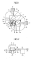
- Fig. 1 is a plan view showing a waveguide orthomode transducer according to embodiment 1 of the present invention
- Fig. 2 is a side view showing the waveguide orthomode transducer according to embodiment 1 of the present invention.
- Fig. 3 is a side view showing a distribution of electric fields of a basic mode at a branch portion when a horizontally polarized wave is inputted to the waveguide orthomode transducer
- Fig. 4 is a side view showing a distribution of electric fields of a higher mode at the branch portion when the higher mode occurs
- Fig. 5 is a perspective diagram showing a distribution of electric fields of the basic mode in a four branch circuit when a horizontally polarized wave is inputted to the waveguide orthomode transducer
- Fig. 6 is a perspective diagram showing a distribution of electric fields of the higher mode in the four branch circuit when the higher mode occurs.
- a circular main waveguide 1 conducts a circularly-polarized-wave signal inputted thereto via an input/output terminal P1 (i.e., a vertically polarized electric wave and a horizontally polarized electric wave).
- a square main waveguide (i.e., a first square main waveguide) 2 conducts the circularly-polarized-wave signal conducted by the circular main waveguide 1.
- Another square main waveguide (i.e., a second square main waveguide) 3 has an opening diameter narrower than that of the square main waveguide 2, branches the horizontally polarized electric wave of the circularly-polarized-wave signal conducted by the square main waveguide 2 toward directions designated by an arrow H (i.e., first horizontal symmetrical directions), and also branches the vertically polarized electric wave of the circularly-polarized-wave signal toward directions designated by an arrow V (i.e., second horizontal symmetrical directions).
- the square main waveguide 3 has a smaller opening diameter than the square main waveguide 2, and the square main waveguide 2 has a smaller opening diameter than the circular main waveguide 1, as previously mentioned.
- the square main waveguide 3 can have a larger opening diameter than the square main waveguide 2, and the square main waveguide 2 can have a larger opening diameter than the circular main waveguide 1.
- a short-circuit plate 4 blocks one end of the square main waveguide 3, and a quadrangular-pyramid-shaped metallic block 5 is placed on the short-circuit plate 4 and separates the incoming circularly-polarized-wave signal into the vertically polarized electric wave and the horizontally polarized electric wave.
- An electric wave branch means is comprised of the circular main waveguide 1, the square main waveguides 2 and 3, the short-circuit plate 4, and the quadrangular-pyramid-shaped metallic block 5.
- Rectangular waveguide branching units 6a and 6d are connected to side walls of the square main waveguide 3 at right angles with respect to the four axes of the square main waveguide 3, respectively.
- Rectangular waveguide multi stage transformers 7a to 7d are connected to the rectangular waveguide branching units 6a to 6d, respectively, and have their respective axes which are curved in an H plane.
- the rectangular waveguide multi stage transformers 7a to 7d are transformers each of which has an opening diameter that decreases with distance from a corresponding one of the rectangular waveguide branching units 6a to 6d.
- a rectangular waveguide four-branch circuit 8 combines a horizontally polarized electric wave conducted by the rectangular waveguide multi stage transformer 7a and a horizontally polarized electric wave conducted by the rectangular waveguide multi stage transformer 7b into a composite signal, and outputs an electric wave of a basic mode included in the composite signal to an input/output terminal P2, and outputs an electric wave of a higher mode to an input/output terminal P4.
- the input/output terminal P4 has an end that is blocked by a short-circuit plate 9 and is constructed of a dielectric with loss.
- a rectangular waveguide four-branch circuit 10 combines a vertically polarized electric wave conducted by the rectangular waveguide multi stage transformer 7c and a vertically polarized electric wave conducted by the rectangular waveguide multi stage transformer 7d into a composite signal, and outputs an electric wave of a basic mode included in the composite signal to an input/output terminal P3, and outputs an electric waves of a higher mode to an input/output terminal P5.
- the input/output terminal P5 has an end that is blocked by a short-circuit plate 11 and is constructed of a dielectric with loss.
- the rectangular waveguide branching units 6a and 6b, the rectangular waveguide multi stage transformers 7a and 7b, and the rectangular waveguide four-branch circuit 8 constitute a first radio wave conducting means
- the rectangular waveguide branching units 6c and 6d, the rectangular waveguide multi stage transformers 7c and 7d, and the rectangular waveguide four-branch circuit 10 constitute a second radio wave conducting means.
- the quadrangular-pyramid-shaped metallic block 5 branches the horizontally polarized electric wave H toward the direction of the rectangular waveguide branching unit 6a and the direction of the rectangular waveguide branching unit 6b (i.e., the directions designated by the arrow H of Fig. 1 ).
- each of the rectangular waveguide branching units 6c and 6d is designed so that the gap between upper and lower side walls thereof has a width equal to or less than one half of the free-space wavelength in an available frequency band, the horizontally polarized electric wave H is not branched toward the directions of the rectangular waveguide branching units 6c and 6d (i.e., the directions designated by the arrow V of Fig. 1 ) because of the shielding effects by the rectangular waveguide branching units 6c and 6d, but is branched toward the directions of the rectangular waveguide branching units 6a and 6b (i.e., the directions designated by the arrow H of Fig. 1 ).
- the multi stage transformer can be made to have reflection characteristics showing that the reflection loss is large in a frequency band in the vicinity of the cut-off frequency of the horizontally polarized electric wave H of the basic mode and the reflection loss can be reduced to a very small one in another frequency band which is somewhat higher than the cut-off frequency, by suitably designing the diameter of the circular main waveguide 1 and the diameter and axis length of the square main waveguide 2.
- the reflection characteristics of the multi stage transformer are similar to those of the above-mentioned branch portion.
- the above-mentioned circular-to-rectangular waveguide multi stage transformer is placed at a position where electric waves reflected from the branch portion and electric waves reflected from the above-mentioned circular-to-rectangular waveguide multi stage transformer cancel each other out in the frequency band in the vicinity of the cut-off frequency of the horizontally polarized electric wave H of the basic mode, the degradation in the reflection characteristics in the frequency band in the vicinity of the cut-off frequency can be suppressed without degradation in the good reflection characteristics in the other frequency band which is somewhat higher than the cut-off frequency of the horizontally polarized electric wave H of the basic mode.
- each of the rectangular waveguide multi stage transformers 7a and 7b has a curved axis, and two or more steps are formed on an upper wall of each of the rectangular waveguide multi stage transformers 7a and 7b and are arranged at intervals of about 1/4 of the wavelength of electric waves conducting through the waveguide along a direction of the centerline of the waveguide, a part conducting toward the rectangular waveguide branching unit 6a and another part conducting toward the rectangular waveguide branching unit 6b, into which the electric wave H has been separated, are combined into a composite electric wave by the rectangular waveguide four-branch circuit 8, and the electric wave is efficiently outputted via the input/output terminal P2 without degradation in the reflection characteristics in the other frequency band which is somewhat higher than the cut-off frequency of the horizontally polarized electric wave H of the basic mode (see Fig. 5 ).
- the quadrangular-pyramid-shaped metallic block 5 branches the vertically polarized electric wave V toward the direction of the rectangular waveguide branching unit 6c and the direction of the rectangular waveguide branching unit 6d (i.e., the directions designated by the arrow V of Fig. 1 ).
- each of the rectangular waveguide branching units 6a and 6b is designed so that the gap between upper and lower side walls thereof has a width equal to or less than one half of the free-space wavelength in the available frequency band, the vertically polarized electric wave V is not branched toward the directions of the rectangular waveguide branching units 6a and 6b (i.e., the directions designated by the arrow H of Fig. 1 ) because of the shielding effects by the rectangular waveguide branching units 6a and 6b, but is branched toward the directions of the rectangular waveguide branching units 6c and 6d (i.e., the directions designated by the arrow V of Fig. 1 ).
- the orientations of electric fields can be changed along with the quadrangular-pyramid-shaped metallic block 5 and the short-circuit plate 4, there is provided a distribution of electric fields which is caused by an equivalent structure in which two rectangular waveguide E plane miter bends having excellent reflection characteristics are arranged symmetrically with respect to each other. For this reason, the vertically polarized electric wave V is efficiently outputted toward the rectangular waveguide branching units 6c and 6d while leakage of the vertically polarized electric wave V toward the rectangular waveguide branching units 6a and 6b is prevented.
- the multi stage transformer can be made to have reflection characteristics showing that the reflection loss is large in a frequency band in the vicinity of the cut-off frequency of the vertically polarized electric wave V of the basic mode and the reflection loss can be reduced to a very small one in another frequency band which is somewhat higher than the cut-off frequency, by suitably designing the diameter of the circular main waveguide 1 and the diameter and axis length of the square main waveguide 2.
- the reflection characteristics of the multi stage transformer are similar to those of the above-mentioned branch portion.
- the above-mentioned circular-to-rectangular waveguide multi stage transformer is placed at a position where electric waves reflected from the branch portion and electric waves reflected from the above-mentioned circular-to-rectangular waveguide multi stage transformer cancel each other out in the frequency band in the vicinity of the cut-off frequency of the vertically polarized electric wave V of the basic mode, the degradation in the reflection characteristics in the frequency band in the vicinity of the cut-off frequency can be suppressed without degradation in the good reflection characteristics in the other frequency band which is somewhat higher than the cut-off frequency of the vertically polarized electric wave V of the basic mode.
- each of the rectangular waveguide multi stage transformers 7c and 7d has a curved axis, and two or more steps are formed on an upper wall of each of the rectangular waveguide multi stage transformers 7c and 7d and are arranged at intervals of about 1/4 of the wavelength of electric waves conducting through the waveguide along the direction of the centerline of the waveguide, a part conducting toward the rectangular waveguide branching unit 6c and another part conducting toward the rectangular waveguide branching unit 6d, into which the electric wave V has been separated, are combined into a composite electric wave by the rectangular waveguide four-branch circuit 10, and the electric wave is efficiently outputted via the input/output terminal P3 without degradation in the reflection characteristics in the other frequency band which is somewhat higher than the cut-off frequency of the vertically polarized electric wave V of the basic mode (see Fig. 5 ).
- a horizontally polarized electric wave of the basic mode and a vertically polarized electric wave of the basic mode are inputted to the waveguide orthomode transducer via the input/output terminal P1, as previously mentioned.
- a higher mode e.g., TE11 mode
- a horizontally polarized electric wave H of the higher mode is conducted through the insides of the rectangular waveguide multi stage transformer 7a and 7b, and a vertically polarized electric wave V of the higher mode is conducted through the insides of the rectangular waveguide multi stage transformer 7c and 7d.
- the two conducted waves are respectively combined by the rectangular waveguide four-branch circuits 8 and 10, and are respectively outputted to the input/output terminals P4 and P5.
- each of the input/output terminals P4 and P5 is constructed of a dielectric with loss, the electric waves of the higher mode combined by the rectangular waveguide four-branch circuits 8 and 10 are respectively absorbed by the input/output terminals P4 and P5.
- the description of the above-mentioned principle of operation of the waveguide orthomode transducer is directed to the case where the input/output terminal P1 is used as the input terminal and the input/output terminals P2 and P3 are used as the output terminal, the principle of operation of the waveguide orthomode transducer can be applied to a case where the input/output terminals P2 and P3 are used as the input terminal and the input/output terminal P1 is used as the output terminal.
- the waveguide orthomode transducer in accordance with this embodiment 1 is provided with a first radio wave conducting means for conducting an electric wave of a horizontally polarized wave branched by an electric wave branch means, for conducting another electric wave of the horizontally polarized wave, for combining the electric waves of the horizontally polarized wave into one electric wave and dividing this electric wave into an electric wave of a basic mode and an electric wave of a higher mode, and for outputting them, and a second radio wave conducting means for conducting one electric wave of a vertically polarized wave branched by the electric wave branch means, for conducting another electric wave of the vertically polarized wave, for combining the electric waves of the vertically polarized wave into one electric wave and dividing this electric wave into an electric wave of a basic mode and an electric wave of a higher mode, and for outputting them. Therefore, the present embodiment offers an advantage of being able to do miniaturization of the waveguide orthomode transducer and reduce the length of the axis of the waveguide
- the present embodiment offers an advantage of being able to provide good reflection and isolation characteristics in a wide frequency band including frequencies close to the cut-off frequency of the basic mode of the square main waveguide. Since the lengths of the square main waveguides along the direction of the axis of the waveguides can be reduced, the waveguide orthomode transducer can come down in size.
- the present embodiment offers another advantage of being able to reduce the degree of difficulty in machining the waveguide orthomode transducer and hence to reduce the cost of the waveguide orthomode transducer.
- the circular main waveguide 1 is connected to the upper end of the square main waveguide 2, as previously mentioned. As shown in Fig. 7 , the circular main waveguide 1 does not have to be connected to the upper end of the square main waveguide 2.
- the square main waveguide 3 has a smaller opening diameter than the square main waveguide 2.
- the square main waveguide 3 can have a larger opening diameter than the square main waveguide 2.
- the waveguide orthomode transducer according to the present invention can be used in, for example, a VHF band, a UHF band, a microwave band, and a millimeter wave band.
Landscapes
- Waveguide Switches, Polarizers, And Phase Shifters (AREA)
Description
- The present invention relates to a waveguide orthomode transducer used in, for example, a VHF band, a UHF band, a microwave band, and a millimeter wave band.
- A prior art waveguide orthomode transducer is provided with a main waveguide including a metallic thin plate disposed at its branch portion, the metallic thin plate having circular notches which are so formed as to be bilaterally symmetric with each other.
- Since this metallic thin plate is so formed, a horizontally polarized electric wave H of a basic mode inputted to the waveguide orthomode transducer via an input terminal P1 is branched into two routes which are right-angled and symmetric with respect to the direction of the axis of the main waveguide, and the two parts are outputted from output terminals P3 and P4, respectively.
- On the other hand, a vertically polarized electric wave V of a basic mode inputted to the waveguide orthomode transducer via the input terminal P1 is outputted from another output terminal P2 which is opposite to the input terminal P1 (refer to document
JP 11-330801 A Fig. 1 ). - A problem with the prior art waveguide orthomode transducer constructed as mentioned above is that since a metallic thin plate is inserted into the branch portion of the main waveguide, the length of the main waveguide along the direction of the axis becomes long and it is therefore difficult to do miniaturization of the waveguide orthomode transducer with respect to the direction of the axis of the main waveguide and to reduce the length of the main waveguide along the direction of the axis.
- Since there is a large change in the wavelength of electric waves in the waveguide with respect to frequency in a frequency band in the vicinity of the cut-off frequency of the vertically polarized electric wave of the basic mode and the horizontally polarized wave, and there is also a rapid change in the impedance discontinuity with respect to frequency at the branch portion of the main waveguide, it is difficult to suppress degradation in the reflection characteristics of both the vertically polarized wave and the horizontally polarized wave in the frequency band in the vicinity of the cut-off frequency.
- The article "Classification of Ortho-Mode Transducer" by Anton M. Boifot discloses an orthomode transducer with an electric branch means and two radio wave conducting means, wherein each radio wave conducting means are split into symmetrical E-plane (horizontal and vertical) bends, and a waveguide circuit combines the waves transmitted in each bend, in the horizontal and in the vertical direction, to obtain an electric wave in the basic mode.
- Other state of the art orthomode transducers are shown in the documents
US 6 087 908 A andJP 61-52002 A US 6 087 908 A discloses an orthomode transducer comprising an electric wave branch means for branching a horizontally polarized electric wave included in a circularly-polarized-wave signal inputted thereto and a vertically polarized electric wave included in the circularly-polarized-wave signal, a first radio wave conducting means for conducting the horizontally polarized electric wave branched by the electric wave branch means, and a second radio wave conducting means for conducting one electric wave of the vertically polarized electric wave branched by the electric wave branch means. None of these orthomode transducers, however, solve the problem of undesired higher modes which occur in an output signal. - The present invention is made in order to solve the above-mentioned problems, and it is therefore an object of the present invention to provide a high-performance waveguide orthomode transducer that can come down in size and can have a waveguide whose axis is downsized.
- A waveguide orthomode transducer in accordance with the present invention is provided by the wording of
claim 1. -
-
Fig. 1 is a plan view showing a waveguide orthomode transducer according toembodiment 1 of the present invention; -
Fig. 2 is a side view showing the waveguide orthomode transducer according toembodiment 1 of the present invention; -
Fig. 3 is a side view showing a distribution of electric fields of a basic mode at a branch portion when a horizontally polarized wave is inputted to the waveguide orthomode transducer; -
Fig. 4 is a side view showing a distribution of electric fields of a higher mode at the branch portion when the higher mode occurs; -
Fig. 5 is a perspective diagram showing a distribution of electric fields of the basic mode in a four branch circuit when a horizontally polarized wave is inputted to the waveguide orthomode transducer; -
Fig. 6 is a perspective diagram showing a distribution of electric fields of the higher mode in the four branch circuit when the higher mode occurs; and -
Fig. 7 is a side view showing a waveguide orthomode transducer according toembodiment 2 of the present invention; - Hereafter, in order to explain this invention in greater detail, the preferred embodiments of the present invention will be described with reference to the accompanying drawings.
Embodiment 1. -
Fig. 1 is a plan view showing a waveguide orthomode transducer according toembodiment 1 of the present invention, andFig. 2 is a side view showing the waveguide orthomode transducer according toembodiment 1 of the present invention. -
Fig. 3 is a side view showing a distribution of electric fields of a basic mode at a branch portion when a horizontally polarized wave is inputted to the waveguide orthomode transducer,Fig. 4 is a side view showing a distribution of electric fields of a higher mode at the branch portion when the higher mode occurs,Fig. 5 is a perspective diagram showing a distribution of electric fields of the basic mode in a four branch circuit when a horizontally polarized wave is inputted to the waveguide orthomode transducer, andFig. 6 is a perspective diagram showing a distribution of electric fields of the higher mode in the four branch circuit when the higher mode occurs. - In the figures, a circular
main waveguide 1 conducts a circularly-polarized-wave signal inputted thereto via an input/output terminal P1 (i.e., a vertically polarized electric wave and a horizontally polarized electric wave). A square main waveguide (i.e., a first square main waveguide) 2 conducts the circularly-polarized-wave signal conducted by the circularmain waveguide 1. Another square main waveguide (i.e., a second square main waveguide) 3 has an opening diameter narrower than that of the squaremain waveguide 2, branches the horizontally polarized electric wave of the circularly-polarized-wave signal conducted by the squaremain waveguide 2 toward directions designated by an arrow H (i.e., first horizontal symmetrical directions), and also branches the vertically polarized electric wave of the circularly-polarized-wave signal toward directions designated by an arrow V (i.e., second horizontal symmetrical directions). - In the example of
Figs. 1 and 2 , the squaremain waveguide 3 has a smaller opening diameter than the squaremain waveguide 2, and the squaremain waveguide 2 has a smaller opening diameter than the circularmain waveguide 1, as previously mentioned. As an alternative, the squaremain waveguide 3 can have a larger opening diameter than the squaremain waveguide 2, and the squaremain waveguide 2 can have a larger opening diameter than the circularmain waveguide 1. - A short-
circuit plate 4 blocks one end of the squaremain waveguide 3, and a quadrangular-pyramid-shapedmetallic block 5 is placed on the short-circuit plate 4 and separates the incoming circularly-polarized-wave signal into the vertically polarized electric wave and the horizontally polarized electric wave. An electric wave branch means is comprised of the circularmain waveguide 1, the squaremain waveguides circuit plate 4, and the quadrangular-pyramid-shapedmetallic block 5. - Rectangular
waveguide branching units main waveguide 3 at right angles with respect to the four axes of the squaremain waveguide 3, respectively. Rectangular waveguidemulti stage transformers 7a to 7d are connected to the rectangularwaveguide branching units 6a to 6d, respectively, and have their respective axes which are curved in an H plane. The rectangular waveguidemulti stage transformers 7a to 7d are transformers each of which has an opening diameter that decreases with distance from a corresponding one of the rectangularwaveguide branching units 6a to 6d. - A rectangular waveguide four-
branch circuit 8 combines a horizontally polarized electric wave conducted by the rectangular waveguidemulti stage transformer 7a and a horizontally polarized electric wave conducted by the rectangular waveguidemulti stage transformer 7b into a composite signal, and outputs an electric wave of a basic mode included in the composite signal to an input/output terminal P2, and outputs an electric wave of a higher mode to an input/output terminal P4. The input/output terminal P4 has an end that is blocked by a short-circuit plate 9 and is constructed of a dielectric with loss. - A rectangular waveguide four-
branch circuit 10 combines a vertically polarized electric wave conducted by the rectangular waveguidemulti stage transformer 7c and a vertically polarized electric wave conducted by the rectangular waveguidemulti stage transformer 7d into a composite signal, and outputs an electric wave of a basic mode included in the composite signal to an input/output terminal P3, and outputs an electric waves of a higher mode to an input/output terminal P5. The input/output terminal P5 has an end that is blocked by a short-circuit plate 11 and is constructed of a dielectric with loss. - The rectangular
waveguide branching units multi stage transformers branch circuit 8 constitute a first radio wave conducting means, and the rectangularwaveguide branching units multi stage transformers branch circuit 10 constitute a second radio wave conducting means. - Next, the operation of the waveguide orthomode transducer in accordance with
embodiment 1 of the present invention will be explained. - When a horizontally polarized electric wave H of a basic mode (i.e., TE01 mode) is inputted to the waveguide orthomode transducer via the input/output terminal P1, the circular
main waveguide 1 and the squaremain waveguides - When the horizontally polarized electric wave H then reaches the quadrangular-pyramid-shaped
metallic block 5, the quadrangular-pyramid-shapedmetallic block 5 branches the horizontally polarized electric wave H toward the direction of the rectangularwaveguide branching unit 6a and the direction of the rectangularwaveguide branching unit 6b (i.e., the directions designated by the arrow H ofFig. 1 ). - In other words, since each of the rectangular
waveguide branching units waveguide branching units Fig. 1 ) because of the shielding effects by the rectangularwaveguide branching units waveguide branching units Fig. 1 ). - Furthermore, as shown in
Fig. 3 , since the orientations of electric fields can be changed along with the quadrangular-pyramid-shapedmetallic block 5 and the short-circuit plate 4, there is provided a distribution of electric fields which is caused by an equivalent structure in which two rectangular waveguide E plane miter bends having excellent reflection characteristics are arranged symmetrically with respect to each other. For this reason, the horizontally polarized electric wave H is efficiently outputted toward the rectangularwaveguide branching units waveguide branching units - Since a connecting point between the circular
main waveguide 1 and the squaremain waveguide 2, the squaremain waveguide 2, and a connecting point between the squaremain waveguide 2 and the squaremain waveguide 3 serve as a circular-to-rectangular waveguide multi stage transformer, the multi stage transformer can be made to have reflection characteristics showing that the reflection loss is large in a frequency band in the vicinity of the cut-off frequency of the horizontally polarized electric wave H of the basic mode and the reflection loss can be reduced to a very small one in another frequency band which is somewhat higher than the cut-off frequency, by suitably designing the diameter of the circularmain waveguide 1 and the diameter and axis length of the squaremain waveguide 2. The reflection characteristics of the multi stage transformer are similar to those of the above-mentioned branch portion. Therefore, when the above-mentioned circular-to-rectangular waveguide multi stage transformer is placed at a position where electric waves reflected from the branch portion and electric waves reflected from the above-mentioned circular-to-rectangular waveguide multi stage transformer cancel each other out in the frequency band in the vicinity of the cut-off frequency of the horizontally polarized electric wave H of the basic mode, the degradation in the reflection characteristics in the frequency band in the vicinity of the cut-off frequency can be suppressed without degradation in the good reflection characteristics in the other frequency band which is somewhat higher than the cut-off frequency of the horizontally polarized electric wave H of the basic mode. - In addition, since each of the rectangular waveguide
multi stage transformers multi stage transformers waveguide branching unit 6a and another part conducting toward the rectangularwaveguide branching unit 6b, into which the electric wave H has been separated, are combined into a composite electric wave by the rectangular waveguide four-branch circuit 8, and the electric wave is efficiently outputted via the input/output terminal P2 without degradation in the reflection characteristics in the other frequency band which is somewhat higher than the cut-off frequency of the horizontally polarized electric wave H of the basic mode (seeFig. 5 ). - On the other hand, when a vertically polarized electric wave V of a basic mode (i.e., TE10 mode) is inputted thereto via the input/output terminal P1, the circular
main waveguide 1 and the squaremain waveguides - When the vertically polarized electric wave V then reaches the quadrangular-pyramid-shaped
metallic block 5, the quadrangular-pyramid-shapedmetallic block 5 branches the vertically polarized electric wave V toward the direction of the rectangularwaveguide branching unit 6c and the direction of the rectangularwaveguide branching unit 6d (i.e., the directions designated by the arrow V ofFig. 1 ). - In other words, since each of the rectangular
waveguide branching units waveguide branching units Fig. 1 ) because of the shielding effects by the rectangularwaveguide branching units waveguide branching units Fig. 1 ). - Furthermore, since the orientations of electric fields can be changed along with the quadrangular-pyramid-shaped
metallic block 5 and the short-circuit plate 4, there is provided a distribution of electric fields which is caused by an equivalent structure in which two rectangular waveguide E plane miter bends having excellent reflection characteristics are arranged symmetrically with respect to each other. For this reason, the vertically polarized electric wave V is efficiently outputted toward the rectangularwaveguide branching units waveguide branching units - Since the connecting point between the circular
main waveguide 1 and the squaremain waveguide 2, the squaremain waveguide 2, and the connecting point between the squaremain waveguide 2 and the squaremain waveguide 3 serve as the circular-to-rectangular waveguide multi stage transformer, the multi stage transformer can be made to have reflection characteristics showing that the reflection loss is large in a frequency band in the vicinity of the cut-off frequency of the vertically polarized electric wave V of the basic mode and the reflection loss can be reduced to a very small one in another frequency band which is somewhat higher than the cut-off frequency, by suitably designing the diameter of the circularmain waveguide 1 and the diameter and axis length of the squaremain waveguide 2. The reflection characteristics of the multi stage transformer are similar to those of the above-mentioned branch portion. Therefore, when the above-mentioned circular-to-rectangular waveguide multi stage transformer is placed at a position where electric waves reflected from the branch portion and electric waves reflected from the above-mentioned circular-to-rectangular waveguide multi stage transformer cancel each other out in the frequency band in the vicinity of the cut-off frequency of the vertically polarized electric wave V of the basic mode, the degradation in the reflection characteristics in the frequency band in the vicinity of the cut-off frequency can be suppressed without degradation in the good reflection characteristics in the other frequency band which is somewhat higher than the cut-off frequency of the vertically polarized electric wave V of the basic mode. - In addition, since each of the rectangular waveguide
multi stage transformers multi stage transformers waveguide branching unit 6c and another part conducting toward the rectangularwaveguide branching unit 6d, into which the electric wave V has been separated, are combined into a composite electric wave by the rectangular waveguide four-branch circuit 10, and the electric wave is efficiently outputted via the input/output terminal P3 without degradation in the reflection characteristics in the other frequency band which is somewhat higher than the cut-off frequency of the vertically polarized electric wave V of the basic mode (seeFig. 5 ). - In this embodiment, a horizontally polarized electric wave of the basic mode and a vertically polarized electric wave of the basic mode are inputted to the waveguide orthomode transducer via the input/output terminal P1, as previously mentioned. When the symmetric property of the square
main waveguide 2 collapses due to machining errors etc. and a higher mode (e.g., TE11 mode) occurs at a discontinuous portion, for example, a distribution of electric fields as shown inFig. 4 is provided. As a result, a horizontally polarized electric wave H of the higher mode is conducted through the insides of the rectangular waveguidemulti stage transformer multi stage transformer - In this case, since the distribution of electric fields becomes a one in which two H plane bends are combined, as shown in
Fig. 6 , the two conducted waves are respectively combined by the rectangular waveguide four-branch circuits - Since each of the input/output terminals P4 and P5 is constructed of a dielectric with loss, the electric waves of the higher mode combined by the rectangular waveguide four-
branch circuits - As a result, even if a higher mode occurs due to machining errors etc., it is possible to prevent confinement resonance which is caused by total reflection of in-phase conducted waves by the rectangular waveguide four-
branch circuits - Although the description of the above-mentioned principle of operation of the waveguide orthomode transducer is directed to the case where the input/output terminal P1 is used as the input terminal and the input/output terminals P2 and P3 are used as the output terminal, the principle of operation of the waveguide orthomode transducer can be applied to a case where the input/output terminals P2 and P3 are used as the input terminal and the input/output terminal P1 is used as the output terminal.
- As can be seen from the above description, the waveguide orthomode transducer in accordance with this
embodiment 1 is provided with a first radio wave conducting means for conducting an electric wave of a horizontally polarized wave branched by an electric wave branch means, for conducting another electric wave of the horizontally polarized wave, for combining the electric waves of the horizontally polarized wave into one electric wave and dividing this electric wave into an electric wave of a basic mode and an electric wave of a higher mode, and for outputting them, and a second radio wave conducting means for conducting one electric wave of a vertically polarized wave branched by the electric wave branch means, for conducting another electric wave of the vertically polarized wave, for combining the electric waves of the vertically polarized wave into one electric wave and dividing this electric wave into an electric wave of a basic mode and an electric wave of a higher mode, and for outputting them. Therefore, the present embodiment offers an advantage of being able to do miniaturization of the waveguide orthomode transducer and reduce the length of the axis of the waveguide orthomode transducer, and to enhance the performance of the waveguide orthomode transducer. - In other words, the present embodiment offers an advantage of being able to provide good reflection and isolation characteristics in a wide frequency band including frequencies close to the cut-off frequency of the basic mode of the square main waveguide. Since the lengths of the square main waveguides along the direction of the axis of the waveguides can be reduced, the waveguide orthomode transducer can come down in size.
- Furthermore, since the waveguide orthomode transducer has a structure of not using any metallic thin plate and any metallic post, the present embodiment offers another advantage of being able to reduce the degree of difficulty in machining the waveguide orthomode transducer and hence to reduce the cost of the waveguide orthomode transducer.
- In accordance with above-mentioned
embodiment 1, the circularmain waveguide 1 is connected to the upper end of the squaremain waveguide 2, as previously mentioned. As shown inFig. 7 , the circularmain waveguide 1 does not have to be connected to the upper end of the squaremain waveguide 2. - In the example of
Fig. 7 , the squaremain waveguide 3 has a smaller opening diameter than the squaremain waveguide 2. As an alternative, the squaremain waveguide 3 can have a larger opening diameter than the squaremain waveguide 2. - As mentioned above, the waveguide orthomode transducer according to the present invention can be used in, for example, a VHF band, a UHF band, a microwave band, and a millimeter wave band.
Claims (4)
- A waveguide orthomode transducer comprising:an electric wave branch means (1-5) for branching a horizontally polarized electric wave included in a circularly-polarized-wave signal inputted thereto and a vertically polarized electric wave included in the circularly-polarized-wave signal;a first radio wave conducting means (6a, 6b, 7a, 7b, 8) for conducting the horizontally polarized electric wave branched by said electric wave branch means;and a second radio wave conducting means (6c, 6d, 7c, 7d, 10) for conducting one electric wave of the vertically polarized electric wave branched by said electric wave branch means,wherein the electric wave branch means comprises means for branching the horizontally polarized electric wave into first two directions opposite to each other and for branching the vertically polarized electric wave into another two directions opposite to each other and orthogonal to said first two directions,wherein the first radio wave conducting means comprises a first section (6a, 7a) for conducting a first part of the horizontally polarized electric wave leaving the electric wave branch means into one of the two first direct tions and a second section (6b, 7b) symmetric, with respect to the center of the electric wave branch means, to the first section of the first radio wave conducting means for conducting a second part of the horizontally polarized electric wave leaving the electric wave branch means into the opposite direction,wherein the second radio wave conducting means comprises a first section (6c, 7c) for conducting a first part of the vertically polarized electric wave leaving the electric wave branch means into one of the other two directions and a second section (6d, 7d) symmetric, with respect to the center of the electric wave branch means, to the first section of the second radio wave conducting means for conducting a second part of the vertically polarized electric wave leaving the electric wave branch means into the opposite direction,characterized in that each of said first and second radio wave conducting means further comprise a wave guide four-branch circuit (8, 10) for combining the first and the second part of the electric wave conducted by the respective radio wave conducting means into one electric wave, for dividing this electric wave into an electric wave of a basic mode and an electric wave of a higher mode, and for outputting them,wherein said electric wave branch means (1-5) is provided with a first square main waveguide (2) for conducting the circularly-polarized-wave signal inputted thereto via an input/output terminal (P1), and a second square main waveguide (3), for branching the horizontally polarized electric wave included in the circularly-polarized-wave signal conducted by said first square main waveguide (2) into the first two directions, and for branching the vertically polarized electric wave included in the circularly-polarized-wave signal into the other two directions, the dimensions of both waveguides being different, and wherein the electric wave branch means (1-5) is further provided with a short-circuit plate (4) and a quadrangular-pyramid-shaped metallic block (5) placed on the short-circuit plate.
- The waveguide orthomode transducer according to Claim 1, wherein said electric wave branch means (1-5) is further provided with a circular main waveguide (1) for conducting the circularly-polarized-wave signal inputted thereto via the input/output terminal (P1) and wherein the first square main waveguide (2) is adapted to conduct the circularly-polarized-wave signal conducted by said circular main waveguide (1).
- The waveguide orthomode transducer according to Claim 1 or Claim 2, characterized in that said second square main waveguide (3) has an end which is opposite to another end connected to said first square main waveguide (2) and which is blocked by the short-circuit plate (4) on which the quadrangular-pyramid-shaped metallic block (5) is placed.
- The waveguide orthomode transducer according to Claim 1 or Claim 2, characterized in that each of said first and second radio wave conducting means has a terminal (P4, P5) for outputting an electric wave of a higher mode, which is blocked by a short-circuit plate (9, 11) and which comprises a dielectric with loss.
Applications Claiming Priority (2)
| Application Number | Priority Date | Filing Date | Title |
|---|---|---|---|
| JP2003101798A JP4060228B2 (en) | 2003-04-04 | 2003-04-04 | Waveguide type demultiplexer |
| PCT/JP2004/004859 WO2004091034A1 (en) | 2003-04-04 | 2004-04-02 | Waveguide branching filter/polarizer |
Publications (3)
| Publication Number | Publication Date |
|---|---|
| EP1612880A1 EP1612880A1 (en) | 2006-01-04 |
| EP1612880A4 EP1612880A4 (en) | 2006-05-17 |
| EP1612880B1 true EP1612880B1 (en) | 2009-07-01 |
Family
ID=33156778
Family Applications (1)
| Application Number | Title | Priority Date | Filing Date |
|---|---|---|---|
| EP04725537A Expired - Fee Related EP1612880B1 (en) | 2003-04-04 | 2004-04-02 | Waveguide branching filter/polarizer |
Country Status (5)
| Country | Link |
|---|---|
| US (1) | US7330088B2 (en) |
| EP (1) | EP1612880B1 (en) |
| JP (1) | JP4060228B2 (en) |
| DE (1) | DE602004021789D1 (en) |
| WO (1) | WO2004091034A1 (en) |
Families Citing this family (14)
| Publication number | Priority date | Publication date | Assignee | Title |
|---|---|---|---|---|
| JP4011511B2 (en) * | 2003-04-04 | 2007-11-21 | 三菱電機株式会社 | Antenna device |
| US8081046B2 (en) * | 2006-03-10 | 2011-12-20 | Optim Microwave, Inc. | Ortho-mode transducer with opposing branch waveguides |
| US7397323B2 (en) * | 2006-07-12 | 2008-07-08 | Wide Sky Technology, Inc. | Orthomode transducer |
| ES2379756T3 (en) | 2009-02-02 | 2012-05-03 | Centre National D'etudes Spatiales | Orthodontic waveguide transducer |
| CA2801948C (en) | 2010-06-08 | 2017-08-08 | National Research Council Of Canada | Orthomode transducer |
| KR101019670B1 (en) | 2010-08-13 | 2011-03-07 | 엘아이지넥스원 주식회사 | Waveguide transducer |
| US8653906B2 (en) | 2011-06-01 | 2014-02-18 | Optim Microwave, Inc. | Opposed port ortho-mode transducer with ridged branch waveguide |
| US8994474B2 (en) | 2012-04-23 | 2015-03-31 | Optim Microwave, Inc. | Ortho-mode transducer with wide bandwidth branch port |
| US20130314172A1 (en) * | 2012-05-25 | 2013-11-28 | Government Of The United States, As Represented By The Secretary Of The Air Force | Broadband Magic Tee |
| US9203128B2 (en) | 2012-10-16 | 2015-12-01 | Honeywell International Inc. | Compact twist for connecting orthogonal waveguides |
| US9406987B2 (en) | 2013-07-23 | 2016-08-02 | Honeywell International Inc. | Twist for connecting orthogonal waveguides in a single housing structure |
| DE102014000438B4 (en) | 2014-01-17 | 2018-08-09 | Airbus Defence and Space GmbH | Broadband Signal Branching with Sum Signal Absorption (BSmS) |
| JP7252054B2 (en) * | 2019-05-15 | 2023-04-04 | 日本無線株式会社 | Turnstile polarization demultiplexer |
| JP7316836B2 (en) | 2019-05-15 | 2023-07-28 | 日本無線株式会社 | Waveguide polarization demultiplexer |
Family Cites Families (20)
| Publication number | Priority date | Publication date | Assignee | Title |
|---|---|---|---|---|
| JPS6057721B2 (en) | 1977-07-28 | 1985-12-17 | 三菱電機株式会社 | Demultiplexer |
| JPS5811043Y2 (en) * | 1978-02-01 | 1983-03-01 | 日本電気株式会社 | Waveguide synthesis device |
| JPS54115842A (en) | 1978-02-28 | 1979-09-08 | Shimano Industrial Co | Derailer for bicycle |
| JPS5528676A (en) | 1978-08-22 | 1980-02-29 | Mitsubishi Electric Corp | Branch unit |
| DE3020514A1 (en) | 1980-05-30 | 1981-12-10 | Licentia Patent-Verwaltungs-Gmbh, 6000 Frankfurt | AERIAL FEEDING SYSTEM FOR A TRACKABLE AERIAL |
| US4385253A (en) * | 1981-08-21 | 1983-05-24 | General Electric Company | Commutator cone |
| US4467294A (en) * | 1981-12-17 | 1984-08-21 | Vitalink Communications Corporation | Waveguide apparatus and method for dual polarized and dual frequency signals |
| JPS58205304A (en) | 1982-05-25 | 1983-11-30 | Nippon Telegr & Teleph Corp <Ntt> | Polarizer |
| US4504805A (en) * | 1982-06-04 | 1985-03-12 | Andrew Corporation | Multi-port combiner for multi-frequency microwave signals |
| JPS601902A (en) * | 1983-06-16 | 1985-01-08 | Nec Corp | Polarization coupler using two-frequency bands in common |
| JPS6030606U (en) | 1983-08-08 | 1985-03-01 | 日本電信電話株式会社 | polarization splitter |
| JPS60176303A (en) | 1984-02-22 | 1985-09-10 | Mitsubishi Electric Corp | Polarizer |
| JPS6152002A (en) * | 1984-08-20 | 1986-03-14 | Mitsubishi Electric Corp | Microwave feeding circuit |
| JPS62181003U (en) * | 1986-05-08 | 1987-11-17 | ||
| JP3191972B2 (en) * | 1992-01-31 | 2001-07-23 | キヤノン株式会社 | Method for manufacturing semiconductor substrate and semiconductor substrate |
| JP4076594B2 (en) | 1996-07-12 | 2008-04-16 | 三菱電機株式会社 | Waveguide type demultiplexer and polarization demultiplexer |
| FR2763749B1 (en) | 1997-05-21 | 1999-07-23 | Alsthom Cge Alcatel | ANTENNA SOURCE FOR THE TRANSMISSION AND RECEPTION OF POLARIZED MICROWAVE WAVES |
| JP3673080B2 (en) | 1998-05-20 | 2005-07-20 | 三菱電機株式会社 | Waveguide type demultiplexer |
| US6087908A (en) | 1998-09-11 | 2000-07-11 | Channel Master Llc | Planar ortho-mode transducer |
| DE10032172A1 (en) * | 2000-07-01 | 2002-01-17 | Marconi Comm Gmbh | Transition for orthogonally oriented waveguides |
-
2003
- 2003-04-04 JP JP2003101798A patent/JP4060228B2/en not_active Expired - Lifetime
-
2004
- 2004-04-02 DE DE602004021789T patent/DE602004021789D1/en not_active Expired - Lifetime
- 2004-04-02 WO PCT/JP2004/004859 patent/WO2004091034A1/en active Application Filing
- 2004-04-02 US US10/517,838 patent/US7330088B2/en active Active
- 2004-04-02 EP EP04725537A patent/EP1612880B1/en not_active Expired - Fee Related
Also Published As
| Publication number | Publication date |
|---|---|
| US20050200430A1 (en) | 2005-09-15 |
| EP1612880A4 (en) | 2006-05-17 |
| JP4060228B2 (en) | 2008-03-12 |
| JP2004312271A (en) | 2004-11-04 |
| DE602004021789D1 (en) | 2009-08-13 |
| US7330088B2 (en) | 2008-02-12 |
| EP1612880A1 (en) | 2006-01-04 |
| WO2004091034A1 (en) | 2004-10-21 |
Similar Documents
| Publication | Publication Date | Title |
|---|---|---|
| EP1394892B1 (en) | Waveguide type ortho mode transducer | |
| US8816930B2 (en) | Waveguide orthomode transducer | |
| EP1354370B1 (en) | Radio frequency antenna feed structures | |
| US9147921B2 (en) | Compact OMT device | |
| EP1612880B1 (en) | Waveguide branching filter/polarizer | |
| US11569554B2 (en) | Orthomode transducer | |
| EP1291955A1 (en) | Waveguide group branching filter | |
| CA2047815C (en) | Dual septum polarization rotator | |
| US6577207B2 (en) | Dual-band electromagnetic coupler | |
| US7091804B2 (en) | Rotary joint | |
| US6046702A (en) | Probe coupled, multi-band combiner/divider | |
| EP1492193A1 (en) | High frequency module and antenna device | |
| EP0855755B1 (en) | Dielectric line intersection | |
| US11476553B2 (en) | Wideband orthomode transducer | |
| Navarrini et al. | Design of a dual polarization SIS sideband separating receiver based on waveguide OMT for the 275–370 GHz frequency band | |
| US6812804B1 (en) | Broadband polarization filter | |
| JP7305079B2 (en) | polarization demultiplexer | |
| WO2023206814A1 (en) | Orthomode transducer and dual-linearly polarized feed source | |
| JP7316836B2 (en) | Waveguide polarization demultiplexer | |
| KR950004803B1 (en) | Diflexer | |
| JG Fonseca | Recent patents on waveguide orthomode transducers | |
| JP2002185205A (en) | Waveguide branching circuit, waveguide polarization coupler, and waveguide group branching filter |
Legal Events
| Date | Code | Title | Description |
|---|---|---|---|
| PUAI | Public reference made under article 153(3) epc to a published international application that has entered the european phase |
Free format text: ORIGINAL CODE: 0009012 |
|
| 17P | Request for examination filed |
Effective date: 20050201 |
|
| AK | Designated contracting states |
Kind code of ref document: A1 Designated state(s): AT BE BG CH CY CZ DE DK EE ES FI FR GB GR HU IE IT LI LU MC NL PL PT RO SE SI SK TR |
|
| AX | Request for extension of the european patent |
Extension state: AL HR LT LV MK |
|
| RAP1 | Party data changed (applicant data changed or rights of an application transferred) |
Owner name: MITSUBISHI DENKI KABUSHIKI KAISHA |
|
| A4 | Supplementary search report drawn up and despatched |
Effective date: 20060404 |
|
| DAX | Request for extension of the european patent (deleted) | ||
| RBV | Designated contracting states (corrected) |
Designated state(s): DE FR IT |
|
| 17Q | First examination report despatched |
Effective date: 20060713 |
|
| 17Q | First examination report despatched |
Effective date: 20060713 |
|
| GRAP | Despatch of communication of intention to grant a patent |
Free format text: ORIGINAL CODE: EPIDOSNIGR1 |
|
| GRAS | Grant fee paid |
Free format text: ORIGINAL CODE: EPIDOSNIGR3 |
|
| GRAA | (expected) grant |
Free format text: ORIGINAL CODE: 0009210 |
|
| AK | Designated contracting states |
Kind code of ref document: B1 Designated state(s): DE FR IT |
|
| REF | Corresponds to: |
Ref document number: 602004021789 Country of ref document: DE Date of ref document: 20090813 Kind code of ref document: P |
|
| PLBE | No opposition filed within time limit |
Free format text: ORIGINAL CODE: 0009261 |
|
| STAA | Information on the status of an ep patent application or granted ep patent |
Free format text: STATUS: NO OPPOSITION FILED WITHIN TIME LIMIT |
|
| 26N | No opposition filed |
Effective date: 20100406 |
|
| REG | Reference to a national code |
Ref country code: DE Ref legal event code: R084 Ref document number: 602004021789 Country of ref document: DE Effective date: 20120425 |
|
| PG25 | Lapsed in a contracting state [announced via postgrant information from national office to epo] |
Ref country code: IT Free format text: LAPSE BECAUSE OF NON-PAYMENT OF DUE FEES Effective date: 20150402 |
|
| REG | Reference to a national code |
Ref country code: FR Ref legal event code: PLFP Year of fee payment: 13 |
|
| REG | Reference to a national code |
Ref country code: FR Ref legal event code: PLFP Year of fee payment: 14 |
|
| PG25 | Lapsed in a contracting state [announced via postgrant information from national office to epo] |
Ref country code: IT Free format text: LAPSE BECAUSE OF NON-PAYMENT OF DUE FEES Effective date: 20150402 |
|
| PGRI | Patent reinstated in contracting state [announced from national office to epo] |
Ref country code: IT Effective date: 20180104 |
|
| REG | Reference to a national code |
Ref country code: FR Ref legal event code: PLFP Year of fee payment: 15 |
|
| PGFP | Annual fee paid to national office [announced via postgrant information from national office to epo] |
Ref country code: FR Payment date: 20200312 Year of fee payment: 17 |
|
| PGFP | Annual fee paid to national office [announced via postgrant information from national office to epo] |
Ref country code: DE Payment date: 20200317 Year of fee payment: 17 |
|
| PGFP | Annual fee paid to national office [announced via postgrant information from national office to epo] |
Ref country code: IT Payment date: 20200312 Year of fee payment: 17 |
|
| REG | Reference to a national code |
Ref country code: DE Ref legal event code: R119 Ref document number: 602004021789 Country of ref document: DE |
|
| PG25 | Lapsed in a contracting state [announced via postgrant information from national office to epo] |
Ref country code: FR Free format text: LAPSE BECAUSE OF NON-PAYMENT OF DUE FEES Effective date: 20210430 Ref country code: DE Free format text: LAPSE BECAUSE OF NON-PAYMENT OF DUE FEES Effective date: 20211103 |
|
| PG25 | Lapsed in a contracting state [announced via postgrant information from national office to epo] |
Ref country code: IT Free format text: LAPSE BECAUSE OF NON-PAYMENT OF DUE FEES Effective date: 20210430 |