EP1612370A1 - Gerotor mechanism for a screw hydraulic machine - Google Patents
Gerotor mechanism for a screw hydraulic machine Download PDFInfo
- Publication number
- EP1612370A1 EP1612370A1 EP04707700A EP04707700A EP1612370A1 EP 1612370 A1 EP1612370 A1 EP 1612370A1 EP 04707700 A EP04707700 A EP 04707700A EP 04707700 A EP04707700 A EP 04707700A EP 1612370 A1 EP1612370 A1 EP 1612370A1
- Authority
- EP
- European Patent Office
- Prior art keywords
- stator
- rotor
- teeth
- rack
- initial contour
- Prior art date
- Legal status (The legal status is an assumption and is not a legal conclusion. Google has not performed a legal analysis and makes no representation as to the accuracy of the status listed.)
- Granted
Links
Images


Classifications
-
- F—MECHANICAL ENGINEERING; LIGHTING; HEATING; WEAPONS; BLASTING
- F04—POSITIVE - DISPLACEMENT MACHINES FOR LIQUIDS; PUMPS FOR LIQUIDS OR ELASTIC FLUIDS
- F04C—ROTARY-PISTON, OR OSCILLATING-PISTON, POSITIVE-DISPLACEMENT MACHINES FOR LIQUIDS; ROTARY-PISTON, OR OSCILLATING-PISTON, POSITIVE-DISPLACEMENT PUMPS
- F04C2/00—Rotary-piston machines or pumps
- F04C2/08—Rotary-piston machines or pumps of intermeshing-engagement type, i.e. with engagement of co-operating members similar to that of toothed gearing
- F04C2/10—Rotary-piston machines or pumps of intermeshing-engagement type, i.e. with engagement of co-operating members similar to that of toothed gearing of internal-axis type with the outer member having more teeth or tooth-equivalents, e.g. rollers, than the inner member
- F04C2/107—Rotary-piston machines or pumps of intermeshing-engagement type, i.e. with engagement of co-operating members similar to that of toothed gearing of internal-axis type with the outer member having more teeth or tooth-equivalents, e.g. rollers, than the inner member with helical teeth
- F04C2/1071—Rotary-piston machines or pumps of intermeshing-engagement type, i.e. with engagement of co-operating members similar to that of toothed gearing of internal-axis type with the outer member having more teeth or tooth-equivalents, e.g. rollers, than the inner member with helical teeth the inner and outer member having a different number of threads and one of the two being made of elastic materials, e.g. Moineau type
- F04C2/1073—Rotary-piston machines or pumps of intermeshing-engagement type, i.e. with engagement of co-operating members similar to that of toothed gearing of internal-axis type with the outer member having more teeth or tooth-equivalents, e.g. rollers, than the inner member with helical teeth the inner and outer member having a different number of threads and one of the two being made of elastic materials, e.g. Moineau type where one member is stationary while the other member rotates and orbits
- F04C2/1075—Construction of the stationary member
-
- F—MECHANICAL ENGINEERING; LIGHTING; HEATING; WEAPONS; BLASTING
- F03—MACHINES OR ENGINES FOR LIQUIDS; WIND, SPRING, OR WEIGHT MOTORS; PRODUCING MECHANICAL POWER OR A REACTIVE PROPULSIVE THRUST, NOT OTHERWISE PROVIDED FOR
- F03C—POSITIVE-DISPLACEMENT ENGINES DRIVEN BY LIQUIDS
- F03C2/00—Rotary-piston engines
- F03C2/08—Rotary-piston engines of intermeshing-engagement type, i.e. with engagement of co- operating members similar to that of toothed gearing
-
- F—MECHANICAL ENGINEERING; LIGHTING; HEATING; WEAPONS; BLASTING
- F04—POSITIVE - DISPLACEMENT MACHINES FOR LIQUIDS; PUMPS FOR LIQUIDS OR ELASTIC FLUIDS
- F04C—ROTARY-PISTON, OR OSCILLATING-PISTON, POSITIVE-DISPLACEMENT MACHINES FOR LIQUIDS; ROTARY-PISTON, OR OSCILLATING-PISTON, POSITIVE-DISPLACEMENT PUMPS
- F04C2/00—Rotary-piston machines or pumps
- F04C2/08—Rotary-piston machines or pumps of intermeshing-engagement type, i.e. with engagement of co-operating members similar to that of toothed gearing
- F04C2/082—Details specially related to intermeshing engagement type machines or pumps
- F04C2/084—Toothed wheels
Definitions
- the invention relates to gerotor mechanisms of the screw downhole motors used for drilling the oil and gas wells, to the screw pumps employed for extracting oil and for pumping fluids, and also relates to the general-purpose screw hydraulic motors.
- a multi-lead screw gerotor mechanism for a screw downhole motor comprising: a stator having inner helical teeth made of a resilient-elastic material, e.g. of rubber; and a rotor having outer helical teeth, number of which outer teeth by one tooth is less than that of the stator teeth; the rotor axis being shifted with respect to the stator axis by the eccentricity value being half of the teeth s radial height; profiles of the rotor s outer teeth and stator s inner teeth are mutually-enveloping when viewed in the end-face section; and leads of the rotor and stator teeth being proportional to a number of their teeth (see patent RU 2165531, IPC F01C 1/16, 5/04, E21B4/02, 2000).
- profiles of the stator and rotor teeth when viewed in the end-face section, are implemented as the envelopes of the common initial contour of the cycloidal rack defined by the curtailed cycloid equidistance.
- a drawback of this known gerotor mechanism consists in that the total diametric interference in the mechanism is distributed among the stator teeth in the manner that the stator tooth projection is deformed significantly more than its space, so that the rotor axis may shift towards the eccentricity decrease and, consequently, the designed kinematics of the gerotor mechanism may be departed from, wear of apices of the rotor and stator teeth may become more intense, the interference in the pitch point zone may weaken, and service life of a gerotor mechanism may become briefer.
- a stator having inner helical teeth made of a resilient-elastic material, e.g. of rubber; and a rotor having outer helical teeth, number of which outer teeth by one tooth is less than that of the stator teeth; the rotor axis being shifted with respect to the stator axis by the eccentricity value being half of the teeth s radial height; leads of the rotor s and stator s helical teeth are proportional to numbers of their teeth [patent RU 2166603, IPC E21B 4/02, 2000].
- a drawback of the above-recited design is as follows: as the lateral and diametric interferences, evenly distributed, take place, high contact stresses arise and reach their maximum at minimal angles of pressure, which results in one-sided frictional wear of the teeth (at the left side of the rotor teeth, when viewed from the working fluid delivery side), and the friction forces, that develop in meshing, bring about the moments of resistance that prevent the rotor from rotating about its axis and from its planetary motion, which circumstances impair the energy characteristics of a given mechanism.
- the device most pertinent to the claimed invention is a multi-lead gerotor mechanism of a screw hydraulic motor, comprising the following constituents: a stator having inner helical teeth made of a resilient-elastic material, for example of rubber; and a rotor having outer helical teeth whose number is one tooth less than that of the stator s teeth; the rotor axis having been shifted with respect to the stator axis by the eccentricity value being equal to half of the teeth s radial height, the end-face profile of teeth of one of the constituents is implemented as the envelope of the initial contour of the rack defined by the curtailed cycloid equidistance with a shift; and the end-face profile of teeth of the other constituent is implemented as the equidistance of envelope of the first constituent when their centroids are revolved around without slippage, and the equidistance value being half of the value of the diametric interference in meshing (patent RU 2194880, IPC F04C 2
- a drawback of said design consists in that it does not take into account the conditions of sliding of the rotor s helical teeth on those of the stator, i.e. in the zone farthermost from the immediate centre of rotation (from the pitch point), where the sliding speeds are the greatest; and due to the evenly distributed interference there takes place a more severe wear of the stator s resilient-elastic teeth of the stator and that of the rotor teeth s wear-resistance cladding.
- Another drawback consists in that the operation conditions of the gerotor mechanism are not taken into account (temperature, nature of the loads occurring in drilling of rocks of various hardness and composition); for example for the hot wells having a work temperature over 100°C, use of the gerotor mechanisms having a clearance in the rotor-stator meshing is required.
- the use, in such wells, of gerotor mechanisms having the in-meshing interference may result in a more severe wear, a sharp fall of efficiency and seizure of a mechanism.
- Another drawback of the known device is lack of possibility of varying the interference and of correlation adjustment of shapes of the rotor and stator teeth without changing the rotor and/or stator s outer diameters, which does not allow to provide a reliable tightness along the contact lines in the gerotor mechanism, with zero interference in meshing.
- the technical settled by the claimed invention is an improvement of the energy characteristics of the gerotor mechanism in a hydraulic motor when a hydraulic power is applied thereto and when the resulting pressure difference appears in its working members, a prolonged service life and reduced hydro-mechanical losses by virtue of provision of the lateral interference in meshing, an improved tightness along the contact lines and lower contact stresses in the maximum sliding speeds zone by way of re-distribution of the in-meshing interference and optimization of said interference depending on a distance between the immediate centre of rotation (pitch point) and the profiles contact zone.
- Another technical problem is an improved manufacturability and lower cost of the gerotor mechanism by way of simplification of selection of the working pairs according to their radial interference, as well as improved energy characteristics of a gerotor mechanism in conformity with the operation conditions, e.g. for hot wells by way of decreasing the lateral interference or through provision of the side clearance in conjunction with the constant radial interference.
- the profile of a half of each of the teeth in end cross section of the rotor and/or the stator is defined as the envelope of the rack-type tool initial contour formed by the curtailed cycloid equidistance when the rack-type tool initial contour is run without sliding along the corresponding tool circle.
- Coefficient K of the initial contour shape is selected depending on conditions of operation of a gerotor mechanism and in view of versions of assembly thereof, for example - for provision of the lateral interference in meshing of the rotor, having the helical teeth profile according to the claimed invention, with the stator having the profile defined by the cycloidal rack: said coefficient K is selected to be greater than, or equal to 1.
- a radial interference value depends on the selected values of the rack-type tool initial contour shift in formation of the conjugated profiles.
- a gerotor mechanism of a screw hydraulic motor as shown in Fig. 1, 2, comprises stator 1 having inner helical teeth 2, rotor 3 having outer helical teeth 4 whose number by one tooth is less than those of inner helical teeth 2 of stator 1.
- Inner helical teeth 2 of stator 1 are made of a resilient-elastic material, for example of rubber cured onto the inner surface of body 5 of stator 1.
- Axis 6 of stator 1 has shifted with respect to axis 7 of rotor 3 by eccentricity 8 whose value E is equal to half of radial height of teeth 2 and 4.
- Leads of screw lines T1 and T2 of teeth 2 and 4 of, respectively, stator 1 and rotor 3, in Fig. 1, are proportional to numbers of their teeth z 1 and z 2 .
- the contour formed by the circular arcs has the height of 2 E and the length of 2 ⁇ r w1(2) /Z (1)2) .
- profiles of teeth of rotor 3 and/or stator 1 in the end-face section of the gerotor mechanism consists in that said profiles are defined as the envelopes of the rack-type tool initial contour 11 generated by conjugation of circles 12 and 13 having radii r i and r c , respectively (see. Figs. 4 and 5).
- Profile of teeth 4 and 2 is generated when tool s straight line 14 and initial contour 11 associated therewith revolve without sliding around the respective tool s circumferences. As this occurs, the arc having radius r i predominantly forms the profile of apex of tooth 4 of rotor 3 according to Fig. 4, and profile of space of tooth 2 of stator 1 according to Fig.
- the radial interference ⁇ 0 is not present when there are lateral interferences ⁇ 1 , ⁇ 2 , ⁇ 3 , - Fig. 6.
- the example shows meshing of profile of rotor 3 defined as the envelope of initial contour 11 of the rack-type tool and generated by conjugation of circular arcs having coefficient K greater than 1; and meshing of profile of stator 1 defined as the envelope of the rack-type tool initial contour generated by the curtailed cycloid equidistance.
- the lateral interference is distributed in the manner according to which said interference diminishes from the minimum sliding speeds towards the zones where the sliding speeds are maximal, i.e.
- Fig. 6 which feature provides high energy characteristics of the mechanism and mitigates wear of apices of resilient-elastic teeth 2 of stator 1 and apices of teeth 4 of rotor 3.
- the radial interference ⁇ 0 is not present when there are side clearances ⁇ - Fig. 7.
- the example shows meshing of profile of rotor 3 defined as the envelope of the rack-type tool initial contour 11 generated by conjugation of circular arcs having coefficient K less than 1; and meshing of the stator 1 profile defined as the envelope of the rack-type tool initial contour generated by the curtailed cycloid equidistance.
- side clearances ⁇ are distributed such that as compared with a mechanism having the uniform clearance in meshing provided are higher energy characteristics of a gerotor mechanism during its operation in hot wells (at temperatures over 100°C), and the negative influence of the skewing moment is weakened owing to the contact provided at points L and M, according to Fig. 7, and ditto probability that seizure of the gerotor mechanism would occur in a hot well.
- Rotor 3 and stator 1 being assembled such that the profiles - defined as the envelopes of the rack-type tool initial contour 11 generated by conjugation of circular arcs are in contact, in meshing, with the profiles defined as the envelopes of the rack-type tool initial contour generated by the curtailed cycloid equidistance.
- the negative influence of the skewing moment is reduced, for said recesses are distributed evenly along entire length of the gerotor mechanism.
- the claimed gerotor mechanism of a downhole hydraulic motor operates as follows.
- washing fluid is delivered into the upper portion of the gerotor mechanism via a drill string (not shown).
- rotor 3 performs the planetary motion within stator 1, around which rotor revolve helical teeth 4 along helical teeth 2 of stator 1 Fig. 1.
- axis 7 of rotor 3 rotates about axis 6 of stator 1 along the circle having radius E, and rotor 3 itself rotates about its axis 7 in the direction that is opposite to the planetary motion Fig. 2.
- Planetary motion of rotor 3 is transferred to the supporting assembly shaft and to a rock-destruction tool associated therewith.
- rotor 3 When the claimed gerotor mechanism is used in the screw pumps: rotor 3 is caused to rotate and, revolving around teeth 2 of stator 1, converts the rotation mechanical energy to the hydraulic energy of a fluid flow. Kinematics of motion of rotor 3 of a screw pump, and the advantages obtained by using the claimed embodiments of a gerotor mechanism are similar to those described in respect of a screw motor.
- the invention can be suitably used in oil producing industry in the operations for extracting oil and for pumping of fluids, as well as in other industries where various fluids are pumped.
Landscapes
- Engineering & Computer Science (AREA)
- Mechanical Engineering (AREA)
- General Engineering & Computer Science (AREA)
- Chemical & Material Sciences (AREA)
- Combustion & Propulsion (AREA)
- Rotary Pumps (AREA)
- Details And Applications Of Rotary Liquid Pumps (AREA)
- Sampling And Sample Adjustment (AREA)
- Eye Examination Apparatus (AREA)
- Nitrogen And Oxygen Or Sulfur-Condensed Heterocyclic Ring Systems (AREA)
Abstract
Description
- The invention relates to gerotor mechanisms of the screw downhole motors used for drilling the oil and gas wells, to the screw pumps employed for extracting oil and for pumping fluids, and also relates to the general-purpose screw hydraulic motors.
- Known is a multi-lead screw gerotor mechanism for a screw downhole motor, comprising: a stator having inner helical teeth made of a resilient-elastic material, e.g. of rubber; and a rotor having outer helical teeth, number of which outer teeth by one tooth is less than that of the stator teeth; the rotor axis being shifted with respect to the stator axis by the eccentricity value being half of the teeth s radial height; profiles of the rotor s outer teeth and stator s inner teeth are mutually-enveloping when viewed in the end-face section; and leads of the rotor and stator teeth being proportional to a number of their teeth (see patent RU 2165531, IPC F01C 1/16, 5/04, E21B4/02, 2000).
- In the prior-art designs, profiles of the stator and rotor teeth, when viewed in the end-face section, are implemented as the envelopes of the common initial contour of the cycloidal rack defined by the curtailed cycloid equidistance. In this end-face section, thickness Ct of the stator tooth across the mean diameter Dm of the teeth and circular pitch St of these teeth are interrelated according to the following ratio: Ct/St = 0.45 0.65; and thickness CN of the stator tooth across the mean diameter Dm, when viewed in the section perpendicular to the stator tooth s screw line direction, and the stator s tooth radial height h are interrelated according to the following ratio: CN/h≥1.75.
- A drawback of this known gerotor mechanism consists in that the total diametric interference in the mechanism is distributed among the stator teeth in the manner that the stator tooth projection is deformed significantly more than its space, so that the rotor axis may shift towards the eccentricity decrease and, consequently, the designed kinematics of the gerotor mechanism may be departed from, wear of apices of the rotor and stator teeth may become more intense, the interference in the pitch point zone may weaken, and service life of a gerotor mechanism may become briefer.
- Said drawback is partially mitigated in the gerotor mechanism, comprising: a stator having inner helical teeth made of a resilient-elastic material, e.g. of rubber; and a rotor having outer helical teeth, number of which outer teeth by one tooth is less than that of the stator teeth; the rotor axis being shifted with respect to the stator axis by the eccentricity value being half of the teeth s radial height; leads of the rotor s and stator s helical teeth are proportional to numbers of their teeth [patent RU 2166603, IPC E21B 4/02, 2000].
- The stator teeth s profile, when viewed in the end-face section, is implemented as the envelope of the initial contour of the cycloidal rack defined by the equidistance having radius RC1 of the curtailed cycloid; and the rotor teeth profile, when viewed in the end-face section, is implemented as the envelope of the other initial contour of the cycloidal rack having radius RC2 of equidistance, which radius is greater than RC1 or obeys the following ratio: RC2 = RC1 + (0.1 0.5)E, where E is the generating circle radius being equal to the eccentricity value [see said patent No. 2166603].
- Another version of said known design of a gerotor mechanism is such that the stator teeth s profile, when viewed in the end-face section, is implemented as the envelope of the initial contour of the cycloidal rack defined by the equidistance having radius RC1 of the curtailed cycloid; and the rotor teeth s profile, when viewed in the end-face section, is defined by the conjugated circular arcs; the rotor tooth s projection being defined by arc of radius RB, which radius is greater than radius RC1 of the stator equidistance, or interrelates with said radius according to the following ratio: RC2 = RC1 + (0.1 0.5)E, and the rotor tooth s space profile is defined by the arc having radius RV, which radius depends on a number of rotor s teeth, inner diameter and eccentricity of said rotor (see said patent No. 2166603].
- A drawback of the above-recited design is as follows: as the lateral and diametric interferences, evenly distributed, take place, high contact stresses arise and reach their maximum at minimal angles of pressure, which results in one-sided frictional wear of the teeth (at the left side of the rotor teeth, when viewed from the working fluid delivery side), and the friction forces, that develop in meshing, bring about the moments of resistance that prevent the rotor from rotating about its axis and from its planetary motion, which circumstances impair the energy characteristics of a given mechanism.
- The device most pertinent to the claimed invention is a multi-lead gerotor mechanism of a screw hydraulic motor, comprising the following constituents: a stator having inner helical teeth made of a resilient-elastic material, for example of rubber; and a rotor having outer helical teeth whose number is one tooth less than that of the stator s teeth; the rotor axis having been shifted with respect to the stator axis by the eccentricity value being equal to half of the teeth s radial height, the end-face profile of teeth of one of the constituents is implemented as the envelope of the initial contour of the rack defined by the curtailed cycloid equidistance with a shift; and the end-face profile of teeth of the other constituent is implemented as the equidistance of envelope of the first constituent when their centroids are revolved around without slippage, and the equidistance value being half of the value of the diametric interference in meshing (patent RU 2194880, IPC
F04C 2/16,F04C 5/00, 20.12.2002]. - A drawback of said design consists in that it does not take into account the conditions of sliding of the rotor s helical teeth on those of the stator, i.e. in the zone farthermost from the immediate centre of rotation (from the pitch point), where the sliding speeds are the greatest; and due to the evenly distributed interference there takes place a more severe wear of the stator s resilient-elastic teeth of the stator and that of the rotor teeth s wear-resistance cladding. Another drawback consists in that the operation conditions of the gerotor mechanism are not taken into account (temperature, nature of the loads occurring in drilling of rocks of various hardness and composition); for example for the hot wells having a work temperature over 100°C, use of the gerotor mechanisms having a clearance in the rotor-stator meshing is required. The use, in such wells, of gerotor mechanisms having the in-meshing interference may result in a more severe wear, a sharp fall of efficiency and seizure of a mechanism. Another drawback of the known device is lack of possibility of varying the interference and of correlation adjustment of shapes of the rotor and stator teeth without changing the rotor and/or stator s outer diameters, which does not allow to provide a reliable tightness along the contact lines in the gerotor mechanism, with zero interference in meshing.
- The technical settled by the claimed invention is an improvement of the energy characteristics of the gerotor mechanism in a hydraulic motor when a hydraulic power is applied thereto and when the resulting pressure difference appears in its working members, a prolonged service life and reduced hydro-mechanical losses by virtue of provision of the lateral interference in meshing, an improved tightness along the contact lines and lower contact stresses in the maximum sliding speeds zone by way of re-distribution of the in-meshing interference and optimization of said interference depending on a distance between the immediate centre of rotation (pitch point) and the profiles contact zone.
- Another technical problem is an improved manufacturability and lower cost of the gerotor mechanism by way of simplification of selection of the working pairs according to their radial interference, as well as improved energy characteristics of a gerotor mechanism in conformity with the operation conditions, e.g. for hot wells by way of decreasing the lateral interference or through provision of the side clearance in conjunction with the constant radial interference.
- The above problems are settled by providing a gerotor mechanism for a screw hydraulic machine, said mechanism comprising a stator having inner helical teeth made of a elastoplastic material, e.g. of rubber, and a rotor having outer helical teeth whose number by one tooth is less than that of the stator, leads of screw lines in the stator and the rotor being proportional to numbers of their teeth, the rotor axis being shifted with respect to the stator axis by the eccentricity value being equal to half of the teeth radial height; characterizing in that profiles of the rotor and/or the stator are outlined in the end cross section thereof in the form of the envelop of the initial contour of a rack-type tool, which contour is formed by conjugation of circle arcs when said initial contour of the rack-type tool is run without sliding along corresponding tool circles, the radii of the circle arcs of the initial contour being calculated according to the following expressions:


where
ri is the initial radius of the rack-type tool profile,
K = (0.5 2) is the intitial contour coefficient,
rw1, rw2 are radii of the tool circles of the rotor and the stator, respectively;
E is eccentricity of meshing,
z1, z2 are numbers of teeth of the stator and the rotor, respectively;
rc is the conjugated radius of the rack-type tool profile. - Preferably, the profile of a half of each of the teeth in end cross section of the rotor and/or the stator is defined as the envelope of the rack-type tool initial contour formed by the curtailed cycloid equidistance when the rack-type tool initial contour is run without sliding along the corresponding tool circle.
- Said ratios for the rack-type tool initial contour being obeyed and in assembling of gerotor mechanisms having different versions of profiles: a possibility for providing the in-meshing lateral interference is ensured. Thus, a reliable tightness along the contact lines is achieved when hydraulic-power fluid flows are delivered to a hydraulic motor; and a possibility to reduce the in-meshing radial interference and to assemble the working pairs without their selection is brought about. The moment of resistance forces is lowered owing to a weaker radial interference and lighter contact stresses effected on the areas farthermost from the immediate centre of rotation (from the pitch point), that is in the maximum sliding speeds zone. Conditions of sliding of the rotor s helical teeth over the stator s helical teeth are accommodated by virtue of re-distribution of the in-meshing interference towards the decrease thereof from the minimum sliding speeds zones to those of the maximum sliding speeds.
- Apart form that, selection of coefficient K allows to
- modify the lateral interferences in meshing, with the constant radial interference;
- provide the side clearance in meshing, when the radial interference is present;
- provide the radial clearance in meshing, when the lateral interference is present.
- When profile of one half of each one of the teeth in the end-face section of the rotor and/or stator is implemented as the envelope of the rack-type tool initial contour generated by the curtailed cycloid equidistance; and when profile of the other half of the rotor and/or stator s tooth is implemented as the envelope of rack-type tool initial contour generated by conjugation of circular arcs: these arrangements also allow to take into account conditions of operation of the mechanism and mitigate the one-sided wear of teeth.
- Coefficient K of the initial contour shape is selected depending on conditions of operation of a gerotor mechanism and in view of versions of assembly thereof, for example - for provision of the lateral interference in meshing of the rotor, having the helical teeth profile according to the claimed invention, with the stator having the profile defined by the cycloidal rack: said coefficient K is selected to be greater than, or equal to 1. A radial interference value depends on the selected values of the rack-type tool initial contour shift in formation of the conjugated profiles. If coefficient K is less than 0.5, the rotor tooth thickness diminishes excessively and that of the stator increases accordingly; and if K exceeds 2, the rotor tooth thickness increases excessively and that of the stator diminishes accordingly, which circumstance excludes any possibility to use the claimed rotors and/or stators with those of the gerotor mechanisms operated in Russia.
-
- Fig. 1 shows a longitudinal section of a gerotor mechanism associated with a screw-type downhole hydraulic motor.
- Fig. 2 shows a cross-section of the gerotor mechanism taken along line A-A.
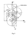
- Fig. 3 shows a diagram for generating the rack-type tool initial contour by conjugating the circular arcs having radii ri and rc.
- Fig. 4 shows a diagram for generating the rotor profile basing on the rack-type tool initial contour generated by conjugation of circular arcs.
- Fig. 5 shows a diagram for generating the stator profile basing on the rack-type tool initial contour generated by conjugation of circular arcs.
- Fig. 6 shows an example of meshing of the stator and rotor, with the zero radial interference, when the lateral interferences are present (shown as enlarged).
- Fig. 7 shows an example of meshing of epy stator and rotor for use in hot wells, with the zero radial interference, when the side clearances are present (shown as enlarged).
- Fig. 8 shows an example of meshing of the stator and rotor whose one half of the profile of each one of the teeth is defined as the envelope of the cycloidal rack (clearances and interferences are enlarged).
- A gerotor mechanism of a screw hydraulic motor, as shown in Fig. 1, 2, comprises
stator 1 having innerhelical teeth 2,rotor 3 having outerhelical teeth 4 whose number by one tooth is less than those of innerhelical teeth 2 ofstator 1. Innerhelical teeth 2 ofstator 1 are made of a resilient-elastic material, for example of rubber cured onto the inner surface ofbody 5 ofstator 1. Axis 6 ofstator 1 has shifted with respect toaxis 7 ofrotor 3 by eccentricity 8 whose value E is equal to half of radial height ofteeth stator 1 having radius c=Ez 1 is in tangency to working centroid 10 (of the initial circumference) ofrotor 3 having radius b=Ez 2 in pitch point P, see Fig. 2. Leads of screw lines T1 and T2 ofteeth stator 1 androtor 3, in Fig. 1, are proportional to numbers of their teeth z1 and z2. - The essential feature of the rack-type tool initial contour of the gerotor mechanism according to the invention consists in that said contour is generated by conjugation of circular arcs, according to Fig. 2, and the initial radius of one of said arc is determined by the following expressions:

or
and the conjugated radius of the other arc is determined as rc = ri/K; and coordinates of the current points m and n of the initial contour are determined by the following expressions:


where
are the central angles having a selected discreteness on the areas of the initial contour having radii ri and rc, respectively;
Ψa = arcsin [(πrw1(2)/z(1)2))/(ri + rc)] is the central angle of the initial contour at the conjugation point of the circular arcs. The contour formed by the circular arcs has the height of 2E and the length of 2πrw1(2)/Z(1)2). Here the angle of the profile of the initial contour conjugated by the circular arcs is determined by the following expressions:
or
see. Fig 3. - The essential feature of profiles of teeth of
rotor 3 and/orstator 1 in the end-face section of the gerotor mechanism consists in that said profiles are defined as the envelopes of the rack-type toolinitial contour 11 generated by conjugation ofcircles teeth straight line 14 andinitial contour 11 associated therewith revolve without sliding around the respective tool s circumferences. As this occurs, the arc having radius ri predominantly forms the profile of apex oftooth 4 ofrotor 3 according to Fig. 4, and profile of space oftooth 2 ofstator 1 according to Fig. 5; and the arc having radius rc predominantly forms the profile of space oftooth 4 ofrotor 3 according to Fig. 4 and profile of apex oftooth 2stator 1 according to Fig. 5. Radii of tool scircumferences 15 ofrotor stator 1, according to Figs. 4 and 5, are selected basing on a number or teeth and an eccentricity value. For provision of predetermined diameters ofrotor 3 with respect to projections ofteeth 4, and ofstator 1 with respect to spaces of teeth 2: values of shift x 2 and x 1 of the initial contours of the rotor and stator, respectively, are defined Figs. 4 and 5. Here profile ofrotor 3 in its end-section is determined by the following expressions:

and the stator profile in its end-face section is determined by the following expressions:

where
ϕd2 = 2{(Yn(m) (x 2 + Xn(m))ctgαpt)/dw2], ϕd1 = 2[(Yn(m)- (x 1 + Xn(m))ctgαpt)/dw1] are the angles of rotation of a moving coordinate system XtOtYt tied to the rack-type tool relative to the rest coordinate system XdOdYd tied to the centre of the corresponding tool s circumference Figs. 4 and 5. - According to an exemplary embodiment of the claimed gerotor mechanism: in meshing of
stator 1 and rotor 3 - the radial interference Δ0 is not present when there are lateral interferences Δ1, Δ2, Δ3, - Fig. 6. The example shows meshing of profile ofrotor 3 defined as the envelope ofinitial contour 11 of the rack-type tool and generated by conjugation of circular arcs having coefficient K greater than 1; and meshing of profile ofstator 1 defined as the envelope of the rack-type tool initial contour generated by the curtailed cycloid equidistance. In this example, the lateral interference is distributed in the manner according to which said interference diminishes from the minimum sliding speeds towards the zones where the sliding speeds are maximal, i.e. towards the zones farthermost from pitch point P (Δ1 < Δ2 < Δ3), Fig. 6, which feature provides high energy characteristics of the mechanism and mitigates wear of apices of resilient-elastic teeth 2 ofstator 1 and apices ofteeth 4 ofrotor 3. - According to another example of embodiment of the claimed gerotor mechanism: in meshing of
stator 1 and rotor 3 - the radial interference Δ0 is not present when there are side clearances λ - Fig. 7. The example shows meshing of profile ofrotor 3 defined as the envelope of the rack-type toolinitial contour 11 generated by conjugation of circular arcs having coefficient K less than 1; and meshing of thestator 1 profile defined as the envelope of the rack-type tool initial contour generated by the curtailed cycloid equidistance. According to this example: side clearances λ are distributed such that as compared with a mechanism having the uniform clearance in meshing provided are higher energy characteristics of a gerotor mechanism during its operation in hot wells (at temperatures over 100°C), and the negative influence of the skewing moment is weakened owing to the contact provided at points L and M, according to Fig. 7, and ditto probability that seizure of the gerotor mechanism would occur in a hot well. - According to another example of embodiment of the claimed gerotor mechanism: when in meshing of
stator 1 androtor 3 the radial interference Δo is absent and there are side clearances λ1, λ2, λ3, and lateral interferences Δ1, Δ2, Δ3 - Fig. 8. This example shows meshing ofrotor 3 andstator 1 wherein one half of profile of each one of the teeth is defined as the envelope of the rack-type tool initial contour generated by conjugation of circular arcs having coefficient K lesser than 1, and the other half of the tooth profile being defined as the envelope of the rack-type tool initial contour generated by the curtailed cycloid equidistance.Rotor 3 andstator 1 being assembled such that the profiles - defined as the envelopes of the rack-type toolinitial contour 11 generated by conjugation of circular arcs are in contact, in meshing, with the profiles defined as the envelopes of the rack-type tool initial contour generated by the curtailed cycloid equidistance. In this example there are side clearances λ1, λ2, λ3, and lateral interferences Δ1, Δ2, Δ3, according to Fig. 8, which circumstance allows to mitigate the one-sided wear of teeth by diminishing the contact stresses that take place in the maximum sliding speeds zones and in the zones of minimal angles of pressure. Further, owing to a pressure difference that appears between the recesses having side clearances and the recesses having lateral interferences: the negative influence of the skewing moment is reduced, for said recesses are distributed evenly along entire length of the gerotor mechanism. - Also possible are further versions of meshing to be provided in the gerotor mechanisms, wherein the correlation adjustment of a tooth shape and modification of an interference value are provided by selection of optimal values of coefficient K and shifts x 1 and x2 of the rack-type tool initial contours in the course of designing a mechanism.
- The claimed gerotor mechanism of a downhole hydraulic motor operates as follows. When a gerotor mechanism is employed in a screw downhole motor: washing fluid is delivered into the upper portion of the gerotor mechanism via a drill string (not shown). Under action of the washing fluid pressure difference,
rotor 3 performs the planetary motion withinstator 1, around which rotor revolvehelical teeth 4 alonghelical teeth 2 ofstator 1 Fig. 1. In so doing,axis 7 ofrotor 3 rotates about axis 6 ofstator 1 along the circle having radius E, androtor 3 itself rotates about itsaxis 7 in the direction that is opposite to the planetary motion Fig. 2. - In terms of kinematics, movement of
rotor 3 with respect tostator 1 is determined by rolling, without sliding, ofcentroid 10 ofrotor 3 having radius b=Ez 2 along centroid 9 ofstator 1 having radius c=Ez 1, the immediate center of rotation ofrotor 3 being disposed at the point of tangency of centroids at pitch point P: Fig. 2. When the meshing takes place, the recesses of high and low pressures are divided along the contact lines, and in this case if there are lateral interferences, then a reliable tightness between the high- and low pressure recesses is provided, which circumstance helps decrease leakages of the working fluid and, consequently, improves the energy characteristics of the claimed gerotor mechanism (capacity and efficiency). Further, for the reason that there is no radial interference and any decrease in the contact stresses in the zone farthermost from the pitch point, where the sliding speeds are the greatest, according to Fig. 6, so the moment of the resistance forces lowers, and apices ofteeth 2 ofstator 1 andteeth 4 ofrotor 3 are worn less, which is also conducive to improvement of the energy characteristics of the gerotor mechanism and its wear-resistance. When there are side clearances in meshing (a mechanism for operation in a hot well), the operation principle of the mechanism is similar to that which is discussed above; tightness being ensured by expansion of resilient-elastic teeth 2 ofstator 1 and ofteeth 4 ofrotor 3; thereby the contact stresses and, accordingly, the friction forces in the mechanism are optimal for ensuring its high energy characteristics and an high wear resistance. - Planetary motion of
rotor 3 is transferred to the supporting assembly shaft and to a rock-destruction tool associated therewith. - When the claimed gerotor mechanism is used in the screw pumps:
rotor 3 is caused to rotate and, revolving aroundteeth 2 ofstator 1, converts the rotation mechanical energy to the hydraulic energy of a fluid flow. Kinematics of motion ofrotor 3 of a screw pump, and the advantages obtained by using the claimed embodiments of a gerotor mechanism are similar to those described in respect of a screw motor. - The invention can be suitably used in oil producing industry in the operations for extracting oil and for pumping of fluids, as well as in other industries where various fluids are pumped.
Claims (2)
- A gerotor mechanism for a screw hydraulic machine, said mechanism comprising
a stator having inner helical teeth made of a elastoplastic material, e.g. of rubber, and
a rotor having outer helical teeth whose number by one tooth is less than that of the stator,
leads of screw lines in the stator and the rotor being proportional to numbers of their teeth,
the rotor axis being shifted with respect to the stator axis by the eccentricity value being equal to half of the teeth radial height; characterized in that
profiles of the rotor and/or the stator are outlined in the end cross section thereof in the form of the envelop of the initial contour of a rack-type tool, which contour is formed by conjugation of circle arcs when said initial contour of the rack-type tool is run without sliding along corresponding tool circles,
the radii of the circle arcs of the initial contour being calculated according to the following expressions:

where
ri is the initial radius of the rack-type tool profile,
K = (0.5 2) is the initial contour shape coefficient,
rw1, rw2 are radii of the tool circles of the rotor and the stator, respectively;
E is eccentricity of meshing,
z1, z2 are numbers of teeth of the stator and the rotor, respectively;
rc is the conjugated radius of the rack-type tool profile. - The gerotor mechanism for a screw hydraulic machine according to claim 1, characterized in that the profile of a half of each of the teeth in end cross section of the rotor and/or the stator is defined as the envelope of the rack-type tool initial contour formed by the curtailed cycloid equidistance when the rack-type tool initial contour is run without sliding along the corresponding tool circle.
Priority Applications (2)
| Application Number | Priority Date | Filing Date | Title |
|---|---|---|---|
| SI200431366T SI1612370T1 (en) | 2003-03-25 | 2004-02-03 | Gerotor mechanism for a screw hydraulic machine |
| CY20101100209T CY1109872T1 (en) | 2003-03-25 | 2010-03-04 | MOTOR ROTATING MACHINE FOR A HYDRAULIC ROLLING MACHINE |
Applications Claiming Priority (2)
| Application Number | Priority Date | Filing Date | Title |
|---|---|---|---|
| RU2003108246/06A RU2228444C1 (en) | 2003-03-25 | 2003-03-25 | Screw hydraulic machine gerotor mechanism |
| PCT/RU2004/000031 WO2004085798A1 (en) | 2003-03-25 | 2004-02-03 | Gerotor mechanism for a screw hydraulic machine |
Publications (3)
| Publication Number | Publication Date |
|---|---|
| EP1612370A1 true EP1612370A1 (en) | 2006-01-04 |
| EP1612370A4 EP1612370A4 (en) | 2006-12-06 |
| EP1612370B1 EP1612370B1 (en) | 2009-12-30 |
Family
ID=32679556
Family Applications (1)
| Application Number | Title | Priority Date | Filing Date |
|---|---|---|---|
| EP04707700A Expired - Lifetime EP1612370B1 (en) | 2003-03-25 | 2004-02-03 | Gerotor mechanism for a screw hydraulic machine |
Country Status (14)
| Country | Link |
|---|---|
| US (1) | US7226279B2 (en) |
| EP (1) | EP1612370B1 (en) |
| CN (1) | CN100412320C (en) |
| AT (1) | ATE453777T1 (en) |
| BR (1) | BRPI0408941A (en) |
| CA (1) | CA2520760C (en) |
| CY (1) | CY1109872T1 (en) |
| DE (1) | DE602004024875D1 (en) |
| DK (1) | DK1612370T3 (en) |
| ES (1) | ES2337141T3 (en) |
| MX (1) | MXPA05010215A (en) |
| RU (1) | RU2228444C1 (en) |
| SI (1) | SI1612370T1 (en) |
| WO (1) | WO2004085798A1 (en) |
Cited By (2)
| Publication number | Priority date | Publication date | Assignee | Title |
|---|---|---|---|---|
| WO2008028075A2 (en) * | 2006-08-31 | 2008-03-06 | Schlumberger Canada Limited | Method and system for managing a drilling operation in a multicomponent particulate system |
| US8301383B2 (en) | 2008-06-02 | 2012-10-30 | Schlumberger Technology Corporation | Estimating in situ mechanical properties of sediments containing gas hydrates |
Families Citing this family (14)
| Publication number | Priority date | Publication date | Assignee | Title |
|---|---|---|---|---|
| JP4169724B2 (en) * | 2003-07-17 | 2008-10-22 | 株式会社山田製作所 | Trochoid oil pump |
| EP1927752B1 (en) | 2005-09-22 | 2018-09-12 | Aisin Seiki Kabushiki Kaisha | Oil pump rotor |
| US20070237642A1 (en) * | 2006-04-10 | 2007-10-11 | Murrow Kurt D | Axial flow positive displacement worm pump |
| US8602127B2 (en) | 2010-12-22 | 2013-12-10 | Baker Hughes Incorporated | High temperature drilling motor drive with cycloidal speed reducer |
| EP3271584B1 (en) | 2015-03-16 | 2020-05-06 | Saudi Arabian Oil Company | Equal-walled gerotor pump for wellbore applications |
| US20170183948A1 (en) * | 2015-12-28 | 2017-06-29 | Saudi Arabian Oil Company | Preconditioning flow to an electrical submersible pump |
| US10385615B2 (en) | 2016-11-10 | 2019-08-20 | Baker Hughes, A Ge Company, Llc | Vibrationless moineau system |
| RU2681875C1 (en) * | 2017-10-06 | 2019-03-13 | Федеральное государственное бюджетное образовательное учреждение высшего образования "Уфимский государственный нефтяной технический университет" | Method for determining tension in a simple pump |
| US11371326B2 (en) | 2020-06-01 | 2022-06-28 | Saudi Arabian Oil Company | Downhole pump with switched reluctance motor |
| US11499563B2 (en) | 2020-08-24 | 2022-11-15 | Saudi Arabian Oil Company | Self-balancing thrust disk |
| US11920469B2 (en) | 2020-09-08 | 2024-03-05 | Saudi Arabian Oil Company | Determining fluid parameters |
| US11644351B2 (en) | 2021-03-19 | 2023-05-09 | Saudi Arabian Oil Company | Multiphase flow and salinity meter with dual opposite handed helical resonators |
| US11591899B2 (en) | 2021-04-05 | 2023-02-28 | Saudi Arabian Oil Company | Wellbore density meter using a rotor and diffuser |
| US11913464B2 (en) | 2021-04-15 | 2024-02-27 | Saudi Arabian Oil Company | Lubricating an electric submersible pump |
Citations (1)
| Publication number | Priority date | Publication date | Assignee | Title |
|---|---|---|---|---|
| RU2202694C1 (en) * | 2002-06-13 | 2003-04-20 | Общество с ограниченной ответственностью фирма "Радиус-Сервис" | Screw hydraulic machine helical gear rotation mechanism |
Family Cites Families (15)
| Publication number | Priority date | Publication date | Assignee | Title |
|---|---|---|---|---|
| SE307736B (en) * | 1964-08-18 | 1969-01-13 | Flygts Pumpar Ab | |
| DE1553146A1 (en) * | 1965-09-16 | 1970-02-05 | Netzsch Maschinenfabrik | Runner for screw pumps |
| GB2084254B (en) | 1980-09-25 | 1983-12-14 | Inst Burovoi Tekhnik | Rotary positive displacement fluid machines |
| US4567953A (en) * | 1980-12-10 | 1986-02-04 | Baldenko Dmitry F | Bottom-hole multistart screw motor |
| JPS59173584A (en) * | 1983-03-23 | 1984-10-01 | Sumitomo Electric Ind Ltd | Rotary pump and its rotor for oil pump lubricating internal-combustion engine |
| DE3345419C2 (en) * | 1983-12-15 | 1986-07-17 | Vsesojuznyj naučno-issledovatel'skij institut burovoj techniki, Moskau/Moskva | Deep-hole screw drive for rock drilling |
| GB2152588B (en) * | 1984-01-14 | 1987-08-26 | Inst Burovoi Tekhnik | Downhole rotary fluid-pressure motor |
| JPS61201891A (en) * | 1985-03-05 | 1986-09-06 | Yamada Seisakusho:Kk | Correction method for inner rotor curve of internal gear pump meshed in trochoid |
| US5120204A (en) * | 1989-02-01 | 1992-06-09 | Mono Pumps Limited | Helical gear pump with progressive interference between rotor and stator |
| CN1027986C (en) * | 1992-07-15 | 1995-03-22 | 地质矿产部石油钻探机械厂 | Screwarbor drilling tool rotor with nitridizing surface treatment |
| DE19821867A1 (en) * | 1998-05-15 | 1999-11-18 | Artemis Kautschuk Kunststoff | Downhole deep drilling motor based on eccentric mono-pump principle |
| RU2165531C1 (en) * | 2000-04-12 | 2001-04-20 | Открытое акционерное общество Научно-производственное объединение "Буровая техника" | Downhole screw motor geared-rotor mechanism |
| AU2001253604A1 (en) * | 2000-04-21 | 2001-11-07 | Aps Technology, Inc. | Improved stator especially adapted for use in a helicoidal pump/motor and method of making same |
| RU2166603C1 (en) * | 2000-07-10 | 2001-05-10 | Открытое акционерное общество Научно-производственное объединение "Буровая техника" | Gerotor mechanism of screw face hydraulic machine |
| RU2194880C2 (en) * | 2001-02-02 | 2002-12-20 | Открытое акционерное общество Научно-производственное объединение "Буровая техника" | Multistart gyrator mechanism of screw hydraulic machine |
-
2003
- 2003-03-25 RU RU2003108246/06A patent/RU2228444C1/en not_active IP Right Cessation
-
2004
- 2004-02-03 DE DE602004024875T patent/DE602004024875D1/en not_active Expired - Lifetime
- 2004-02-03 AT AT04707700T patent/ATE453777T1/en active
- 2004-02-03 CN CNB2004800080123A patent/CN100412320C/en not_active Expired - Fee Related
- 2004-02-03 CA CA2520760A patent/CA2520760C/en not_active Expired - Fee Related
- 2004-02-03 SI SI200431366T patent/SI1612370T1/en unknown
- 2004-02-03 ES ES04707700T patent/ES2337141T3/en not_active Expired - Lifetime
- 2004-02-03 US US10/550,245 patent/US7226279B2/en not_active Expired - Fee Related
- 2004-02-03 MX MXPA05010215A patent/MXPA05010215A/en active IP Right Grant
- 2004-02-03 DK DK04707700.3T patent/DK1612370T3/en active
- 2004-02-03 WO PCT/RU2004/000031 patent/WO2004085798A1/en active Application Filing
- 2004-02-03 BR BRPI0408941-3A patent/BRPI0408941A/en not_active IP Right Cessation
- 2004-02-03 EP EP04707700A patent/EP1612370B1/en not_active Expired - Lifetime
-
2010
- 2010-03-04 CY CY20101100209T patent/CY1109872T1/en unknown
Patent Citations (1)
| Publication number | Priority date | Publication date | Assignee | Title |
|---|---|---|---|---|
| RU2202694C1 (en) * | 2002-06-13 | 2003-04-20 | Общество с ограниченной ответственностью фирма "Радиус-Сервис" | Screw hydraulic machine helical gear rotation mechanism |
Non-Patent Citations (1)
| Title |
|---|
| See also references of WO2004085798A1 * |
Cited By (3)
| Publication number | Priority date | Publication date | Assignee | Title |
|---|---|---|---|---|
| WO2008028075A2 (en) * | 2006-08-31 | 2008-03-06 | Schlumberger Canada Limited | Method and system for managing a drilling operation in a multicomponent particulate system |
| WO2008028075A3 (en) * | 2006-08-31 | 2008-04-17 | Schlumberger Ca Ltd | Method and system for managing a drilling operation in a multicomponent particulate system |
| US8301383B2 (en) | 2008-06-02 | 2012-10-30 | Schlumberger Technology Corporation | Estimating in situ mechanical properties of sediments containing gas hydrates |
Also Published As
| Publication number | Publication date |
|---|---|
| US7226279B2 (en) | 2007-06-05 |
| WO2004085798A1 (en) | 2004-10-07 |
| CA2520760C (en) | 2010-10-19 |
| DK1612370T3 (en) | 2010-04-06 |
| SI1612370T1 (en) | 2010-04-30 |
| BRPI0408941A (en) | 2006-04-18 |
| EP1612370A4 (en) | 2006-12-06 |
| EP1612370B1 (en) | 2009-12-30 |
| CA2520760A1 (en) | 2004-10-07 |
| RU2228444C1 (en) | 2004-05-10 |
| CN100412320C (en) | 2008-08-20 |
| DE602004024875D1 (en) | 2010-02-11 |
| MXPA05010215A (en) | 2006-03-28 |
| CY1109872T1 (en) | 2014-09-10 |
| ES2337141T3 (en) | 2010-04-21 |
| ATE453777T1 (en) | 2010-01-15 |
| US20060216183A1 (en) | 2006-09-28 |
| CN1764769A (en) | 2006-04-26 |
Similar Documents
| Publication | Publication Date | Title |
|---|---|---|
| EP1612370B1 (en) | Gerotor mechanism for a screw hydraulic machine | |
| EP2352921B1 (en) | Tooth profile for rotors of positive displacement external gear pumps | |
| KR910002727B1 (en) | Rotary positive-displacement machine of the helicalrotor type and rotors therefor | |
| US11802558B2 (en) | Axial load in helical trochoidal rotary machines | |
| CN104379936B (en) | Reduce the screw machine of noise | |
| US6213744B1 (en) | Phased rotary displacement device | |
| US5215453A (en) | Gear wheel assembly for hydraulic purposes, and method assembling the same | |
| RU2309237C1 (en) | Gerotor mechanism for hydraulic screw-rotor machine | |
| US10895256B2 (en) | Stator and rotor profile for improved power section performance and reliability | |
| WO1994023206A1 (en) | Hydraulic machine | |
| RU2202694C1 (en) | Screw hydraulic machine helical gear rotation mechanism | |
| US6093004A (en) | Pump/motor apparatus using 2-lobe stator | |
| RU2166603C1 (en) | Gerotor mechanism of screw face hydraulic machine | |
| RU132474U1 (en) | MULTI-STEP GEROTOR MECHANISM OF A SCREW HYDRAULIC MACHINE | |
| RU2194880C2 (en) | Multistart gyrator mechanism of screw hydraulic machine | |
| RU2321767C1 (en) | Screw hydraulic gerotor motor | |
| RU2321768C1 (en) | Screw hydraulic gerotor motor | |
| RU2144618C1 (en) | Screw downhole motor | |
| EP0173778A1 (en) | Improvements relating to pumps | |
| RU2165531C1 (en) | Downhole screw motor geared-rotor mechanism | |
| CN114423554A (en) | Gear with improved profile | |
| US11566617B2 (en) | Toothing system for a gerotor pump, and method for geometric determination thereof | |
| JP2024508049A (en) | Screw assembly for a three-shaft screw pump and a screw pump including the assembly | |
| GB2084254A (en) | Rotary Positive-displacement Fluid-machine | |
| JPS6038514B2 (en) | Multi-start screw type helical planetary gear motor for anti-bottom use |
Legal Events
| Date | Code | Title | Description |
|---|---|---|---|
| PUAI | Public reference made under article 153(3) epc to a published international application that has entered the european phase |
Free format text: ORIGINAL CODE: 0009012 |
|
| 17P | Request for examination filed |
Effective date: 20051007 |
|
| AK | Designated contracting states |
Kind code of ref document: A1 Designated state(s): AT BE BG CH CY CZ DE DK EE ES FI FR GB GR HU IE IT LI LU MC NL PT RO SE SI SK TR |
|
| AX | Request for extension of the european patent |
Extension state: AL LT LV MK |
|
| RIN1 | Information on inventor provided before grant (corrected) |
Inventor name: FADEEV, MIKHAIL VALERIEVICH Inventor name: GLINKIN, ALEKSEI SERGEEVICH Inventor name: ASTAFIEV, SERGEI PETROVICH Inventor name: PUSHKAREV, MAKSIM ANATOLIEVICH Inventor name: ANDOSKIN, VLADIMIR NIKOLAEVICH |
|
| A4 | Supplementary search report drawn up and despatched |
Effective date: 20061108 |
|
| RIC1 | Information provided on ipc code assigned before grant |
Ipc: F01C 1/107 20060101AFI20041014BHEP Ipc: F04C 2/08 20060101ALI20061102BHEP |
|
| 17Q | First examination report despatched |
Effective date: 20071107 |
|
| GRAP | Despatch of communication of intention to grant a patent |
Free format text: ORIGINAL CODE: EPIDOSNIGR1 |
|
| GRAS | Grant fee paid |
Free format text: ORIGINAL CODE: EPIDOSNIGR3 |
|
| GRAA | (expected) grant |
Free format text: ORIGINAL CODE: 0009210 |
|
| RIN1 | Information on inventor provided before grant (corrected) |
Inventor name: FADEEV, MIKHAIL VALERIEVICH Inventor name: ASTAFIEV, SERGEI PETROVICH Inventor name: PUSHKAREV, MAKSIM ANATOLIEVICH Inventor name: GLINKIN, ALEKSEI SERGEEVICH Inventor name: ANDOSKIN, VLADIMIR NIKOLAEVICH |
|
| AK | Designated contracting states |
Kind code of ref document: B1 Designated state(s): AT BE BG CH CY CZ DE DK EE ES FI FR GB GR HU IE IT LI LU MC NL PT RO SE SI SK TR |
|
| AX | Request for extension of the european patent |
Extension state: AL LT LV MK |
|
| REG | Reference to a national code |
Ref country code: GB Ref legal event code: FG4D |
|
| REG | Reference to a national code |
Ref country code: CH Ref legal event code: EP |
|
| REG | Reference to a national code |
Ref country code: RO Ref legal event code: EPE |
|
| REG | Reference to a national code |
Ref country code: IE Ref legal event code: FG4D |
|
| REF | Corresponds to: |
Ref document number: 602004024875 Country of ref document: DE Date of ref document: 20100211 Kind code of ref document: P |
|
| REG | Reference to a national code |
Ref country code: CH Ref legal event code: NV Representative=s name: BOVARD AG PATENTANWAELTE |
|
| REG | Reference to a national code |
Ref country code: GR Ref legal event code: EP Ref document number: 20100400446 Country of ref document: GR |
|
| REG | Reference to a national code |
Ref country code: SE Ref legal event code: TRGR |
|
| REG | Reference to a national code |
Ref country code: DK Ref legal event code: T3 |
|
| REG | Reference to a national code |
Ref country code: NL Ref legal event code: T3 |
|
| REG | Reference to a national code |
Ref country code: ES Ref legal event code: FG2A Ref document number: 2337141 Country of ref document: ES Kind code of ref document: T3 |
|
| REG | Reference to a national code |
Ref country code: SK Ref legal event code: T3 Ref document number: E 7105 Country of ref document: SK |
|
| REG | Reference to a national code |
Ref country code: HU Ref legal event code: AG4A Ref document number: E007753 Country of ref document: HU |
|
| PLBE | No opposition filed within time limit |
Free format text: ORIGINAL CODE: 0009261 |
|
| STAA | Information on the status of an ep patent application or granted ep patent |
Free format text: STATUS: NO OPPOSITION FILED WITHIN TIME LIMIT |
|
| 26N | No opposition filed |
Effective date: 20101001 |
|
| REG | Reference to a national code |
Ref country code: CH Ref legal event code: PFA Owner name: OBSCHESTVO S OGRANICHENNOI OTVETSTVENNOSTYU FIRMA Free format text: OBSCHESTVO S OGRANICHENNOI OTVETSTVENNOSTYU FIRMA RADIUS-SERVIS#UL. GEROEV KHASANA, 50#PERM, 614022 (RU) -TRANSFER TO- OBSCHESTVO S OGRANICHENNOI OTVETSTVENNOSTYU FIRMA RADIUS-SERVIS#UL. GEROEV KHASANA, 50#PERM, 614022 (RU) |
|
| PGFP | Annual fee paid to national office [announced via postgrant information from national office to epo] |
Ref country code: HU Payment date: 20110225 Year of fee payment: 8 Ref country code: MC Payment date: 20110214 Year of fee payment: 8 Ref country code: DK Payment date: 20110210 Year of fee payment: 8 Ref country code: IE Payment date: 20110218 Year of fee payment: 8 |
|
| PGFP | Annual fee paid to national office [announced via postgrant information from national office to epo] |
Ref country code: EE Payment date: 20110209 Year of fee payment: 8 Ref country code: LU Payment date: 20110225 Year of fee payment: 8 Ref country code: FI Payment date: 20110214 Year of fee payment: 8 Ref country code: NL Payment date: 20110216 Year of fee payment: 8 Ref country code: FR Payment date: 20110302 Year of fee payment: 8 Ref country code: IT Payment date: 20110219 Year of fee payment: 8 Ref country code: CZ Payment date: 20110308 Year of fee payment: 8 Ref country code: AT Payment date: 20110214 Year of fee payment: 8 Ref country code: CH Payment date: 20110222 Year of fee payment: 8 Ref country code: BG Payment date: 20110214 Year of fee payment: 8 Ref country code: DE Payment date: 20110218 Year of fee payment: 8 Ref country code: TR Payment date: 20110217 Year of fee payment: 8 Ref country code: SK Payment date: 20110309 Year of fee payment: 8 Ref country code: SE Payment date: 20110214 Year of fee payment: 8 Ref country code: PT Payment date: 20110211 Year of fee payment: 8 Ref country code: SI Payment date: 20110216 Year of fee payment: 8 Ref country code: RO Payment date: 20110214 Year of fee payment: 8 |
|
| PGFP | Annual fee paid to national office [announced via postgrant information from national office to epo] |
Ref country code: GR Payment date: 20110218 Year of fee payment: 8 |
|
| PGFP | Annual fee paid to national office [announced via postgrant information from national office to epo] |
Ref country code: ES Payment date: 20110222 Year of fee payment: 8 Ref country code: BE Payment date: 20110211 Year of fee payment: 8 Ref country code: GB Payment date: 20110217 Year of fee payment: 8 |
|
| PGFP | Annual fee paid to national office [announced via postgrant information from national office to epo] |
Ref country code: CY Payment date: 20110216 Year of fee payment: 8 |
|
| BERE | Be: lapsed |
Owner name: OBSCHESTVO S OGRANICHENNOI OTVETSTVENNOSTYU FIRMA Effective date: 20120228 |
|
| REG | Reference to a national code |
Ref country code: NL Ref legal event code: V1 Effective date: 20120901 |
|
| LTLA | Lt: lapse of european patent or patent extension |
Effective date: 20120203 |
|
| PG25 | Lapsed in a contracting state [announced via postgrant information from national office to epo] |
Ref country code: MC Free format text: LAPSE BECAUSE OF NON-PAYMENT OF DUE FEES Effective date: 20120229 |
|
| REG | Reference to a national code |
Ref country code: CH Ref legal event code: PL |
|
| REG | Reference to a national code |
Ref country code: EE Ref legal event code: MM4A Ref document number: E004246 Country of ref document: EE Effective date: 20120228 |
|
| GBPC | Gb: european patent ceased through non-payment of renewal fee |
Effective date: 20120203 |
|
| REG | Reference to a national code |
Ref country code: GR Ref legal event code: ML Ref document number: 20100400446 Country of ref document: GR Effective date: 20120905 |
|
| PG25 | Lapsed in a contracting state [announced via postgrant information from national office to epo] |
Ref country code: LI Free format text: LAPSE BECAUSE OF NON-PAYMENT OF DUE FEES Effective date: 20120229 Ref country code: EE Free format text: LAPSE BECAUSE OF NON-PAYMENT OF DUE FEES Effective date: 20120228 Ref country code: FI Free format text: LAPSE BECAUSE OF NON-PAYMENT OF DUE FEES Effective date: 20120203 Ref country code: CY Free format text: LAPSE BECAUSE OF NON-PAYMENT OF DUE FEES Effective date: 20120203 Ref country code: CH Free format text: LAPSE BECAUSE OF NON-PAYMENT OF DUE FEES Effective date: 20120229 Ref country code: CZ Free format text: LAPSE BECAUSE OF NON-PAYMENT OF DUE FEES Effective date: 20120203 Ref country code: SE Free format text: LAPSE BECAUSE OF NON-PAYMENT OF DUE FEES Effective date: 20120204 |
|
| REG | Reference to a national code |
Ref country code: SK Ref legal event code: MM4A Ref document number: E 7105 Country of ref document: SK Effective date: 20120203 |
|
| REG | Reference to a national code |
Ref country code: DK Ref legal event code: EBP |
|
| REG | Reference to a national code |
Ref country code: IE Ref legal event code: MM4A |
|
| REG | Reference to a national code |
Ref country code: FR Ref legal event code: ST Effective date: 20121031 |
|
| PG25 | Lapsed in a contracting state [announced via postgrant information from national office to epo] |
Ref country code: HU Free format text: LAPSE BECAUSE OF NON-PAYMENT OF DUE FEES Effective date: 20120204 Ref country code: IT Free format text: LAPSE BECAUSE OF NON-PAYMENT OF DUE FEES Effective date: 20120203 Ref country code: PT Free format text: LAPSE BECAUSE OF NON-PAYMENT OF DUE FEES Effective date: 20120803 Ref country code: SK Free format text: LAPSE BECAUSE OF NON-PAYMENT OF DUE FEES Effective date: 20120203 Ref country code: GR Free format text: LAPSE BECAUSE OF NON-PAYMENT OF DUE FEES Effective date: 20120905 |
|
| REG | Reference to a national code |
Ref country code: AT Ref legal event code: MM01 Ref document number: 453777 Country of ref document: AT Kind code of ref document: T Effective date: 20120203 |
|
| REG | Reference to a national code |
Ref country code: DE Ref legal event code: R119 Ref document number: 602004024875 Country of ref document: DE Effective date: 20120901 |
|
| PG25 | Lapsed in a contracting state [announced via postgrant information from national office to epo] |
Ref country code: BE Free format text: LAPSE BECAUSE OF NON-PAYMENT OF DUE FEES Effective date: 20120228 |
|
| PG25 | Lapsed in a contracting state [announced via postgrant information from national office to epo] |
Ref country code: NL Free format text: LAPSE BECAUSE OF NON-PAYMENT OF DUE FEES Effective date: 20120901 Ref country code: IE Free format text: LAPSE BECAUSE OF NON-PAYMENT OF DUE FEES Effective date: 20120203 Ref country code: FR Free format text: LAPSE BECAUSE OF NON-PAYMENT OF DUE FEES Effective date: 20120229 Ref country code: AT Free format text: LAPSE BECAUSE OF NON-PAYMENT OF DUE FEES Effective date: 20120203 Ref country code: GB Free format text: LAPSE BECAUSE OF NON-PAYMENT OF DUE FEES Effective date: 20120203 |
|
| REG | Reference to a national code |
Ref country code: SI Ref legal event code: KO00 Effective date: 20121204 |
|
| PG25 | Lapsed in a contracting state [announced via postgrant information from national office to epo] |
Ref country code: SI Free format text: LAPSE BECAUSE OF NON-PAYMENT OF DUE FEES Effective date: 20120204 |
|
| PG25 | Lapsed in a contracting state [announced via postgrant information from national office to epo] |
Ref country code: RO Free format text: LAPSE BECAUSE OF NON-PAYMENT OF DUE FEES Effective date: 20120203 |
|
| PG25 | Lapsed in a contracting state [announced via postgrant information from national office to epo] |
Ref country code: DE Free format text: LAPSE BECAUSE OF NON-PAYMENT OF DUE FEES Effective date: 20120901 |
|
| REG | Reference to a national code |
Ref country code: ES Ref legal event code: FD2A Effective date: 20130708 |
|
| PG25 | Lapsed in a contracting state [announced via postgrant information from national office to epo] |
Ref country code: ES Free format text: LAPSE BECAUSE OF NON-PAYMENT OF DUE FEES Effective date: 20120204 Ref country code: BG Free format text: LAPSE BECAUSE OF NON-PAYMENT OF DUE FEES Effective date: 20121231 |
|
| PG25 | Lapsed in a contracting state [announced via postgrant information from national office to epo] |
Ref country code: DK Free format text: LAPSE BECAUSE OF NON-PAYMENT OF DUE FEES Effective date: 20120229 |
|
| PG25 | Lapsed in a contracting state [announced via postgrant information from national office to epo] |
Ref country code: TR Free format text: LAPSE BECAUSE OF NON-PAYMENT OF DUE FEES Effective date: 20120203 Ref country code: LU Free format text: LAPSE BECAUSE OF NON-PAYMENT OF DUE FEES Effective date: 20120203 |