EP1612247A2 - Ink composition for inkjet recording and method of producing lithographic printing plate using the same - Google Patents
Ink composition for inkjet recording and method of producing lithographic printing plate using the same Download PDFInfo
- Publication number
- EP1612247A2 EP1612247A2 EP05013723A EP05013723A EP1612247A2 EP 1612247 A2 EP1612247 A2 EP 1612247A2 EP 05013723 A EP05013723 A EP 05013723A EP 05013723 A EP05013723 A EP 05013723A EP 1612247 A2 EP1612247 A2 EP 1612247A2
- Authority
- EP
- European Patent Office
- Prior art keywords
- group
- ink composition
- substituted
- inkjet recording
- ink
- Prior art date
- Legal status (The legal status is an assumption and is not a legal conclusion. Google has not performed a legal analysis and makes no representation as to the accuracy of the status listed.)
- Granted
Links
- 238000000034 method Methods 0.000 title claims abstract description 65
- 239000000203 mixture Substances 0.000 title claims abstract description 63
- 238000007639 printing Methods 0.000 title claims abstract description 20
- 150000001875 compounds Chemical class 0.000 claims abstract description 81
- 239000000463 material Substances 0.000 claims abstract description 40
- 230000000379 polymerizing effect Effects 0.000 claims abstract description 33
- 239000000758 substrate Substances 0.000 claims abstract description 29
- 238000004040 coloring Methods 0.000 claims abstract description 14
- 230000001678 irradiating effect Effects 0.000 claims abstract description 4
- 125000005842 heteroatom Chemical group 0.000 claims description 21
- 239000003505 polymerization initiator Substances 0.000 claims description 21
- 125000005843 halogen group Chemical group 0.000 claims description 16
- 125000003277 amino group Chemical group 0.000 claims description 15
- NIXOWILDQLNWCW-UHFFFAOYSA-M Acrylate Chemical compound [O-]C(=O)C=C NIXOWILDQLNWCW-UHFFFAOYSA-M 0.000 claims description 13
- 125000002915 carbonyl group Chemical group [*:2]C([*:1])=O 0.000 claims description 13
- 239000000178 monomer Substances 0.000 claims description 13
- 229910052705 radium Inorganic materials 0.000 claims description 13
- 229910052701 rubidium Inorganic materials 0.000 claims description 13
- 125000004435 hydrogen atom Chemical group [H]* 0.000 claims description 12
- 125000004149 thio group Chemical group *S* 0.000 claims description 10
- 229910052799 carbon Inorganic materials 0.000 claims description 9
- 125000001820 oxy group Chemical group [*:1]O[*:2] 0.000 claims description 9
- 125000001476 phosphono group Chemical group [H]OP(*)(=O)O[H] 0.000 claims description 9
- 125000000962 organic group Chemical group 0.000 claims description 8
- 125000000394 phosphonato group Chemical group [O-]P([O-])(*)=O 0.000 claims description 8
- 125000002887 hydroxy group Chemical group [H]O* 0.000 claims description 7
- 125000004093 cyano group Chemical group *C#N 0.000 claims description 6
- 125000000623 heterocyclic group Chemical group 0.000 claims description 6
- 125000002579 carboxylato group Chemical group [O-]C(*)=O 0.000 claims description 5
- 125000000475 sulfinyl group Chemical group [*:2]S([*:1])=O 0.000 claims description 5
- 125000001273 sulfonato group Chemical group [O-]S(*)(=O)=O 0.000 claims description 5
- 125000000472 sulfonyl group Chemical group *S(*)(=O)=O 0.000 claims description 5
- 125000003396 thiol group Chemical group [H]S* 0.000 claims description 5
- 125000000020 sulfo group Chemical group O=S(=O)([*])O[H] 0.000 claims description 4
- 125000000449 nitro group Chemical group [O-][N+](*)=O 0.000 claims description 3
- 125000001183 hydrocarbyl group Chemical group 0.000 claims 1
- -1 poly(hydroxystyrene) Polymers 0.000 description 157
- 239000000049 pigment Substances 0.000 description 45
- 229910052782 aluminium Inorganic materials 0.000 description 32
- XAGFODPZIPBFFR-UHFFFAOYSA-N aluminium Chemical compound [Al] XAGFODPZIPBFFR-UHFFFAOYSA-N 0.000 description 32
- 125000003118 aryl group Chemical group 0.000 description 32
- 238000011282 treatment Methods 0.000 description 30
- 125000000217 alkyl group Chemical group 0.000 description 29
- 125000001424 substituent group Chemical group 0.000 description 29
- 239000006185 dispersion Substances 0.000 description 28
- 238000007789 sealing Methods 0.000 description 20
- 239000002585 base Substances 0.000 description 18
- 125000000547 substituted alkyl group Chemical group 0.000 description 17
- 239000007864 aqueous solution Substances 0.000 description 16
- 239000000126 substance Substances 0.000 description 14
- 150000001768 cations Chemical class 0.000 description 12
- 150000002222 fluorine compounds Chemical class 0.000 description 12
- 230000035945 sensitivity Effects 0.000 description 12
- 229920000642 polymer Polymers 0.000 description 11
- 238000007788 roughening Methods 0.000 description 11
- 238000003860 storage Methods 0.000 description 11
- XLYOFNOQVPJJNP-UHFFFAOYSA-N water Substances O XLYOFNOQVPJJNP-UHFFFAOYSA-N 0.000 description 11
- 125000003342 alkenyl group Chemical group 0.000 description 10
- 125000000304 alkynyl group Chemical group 0.000 description 10
- 239000002270 dispersing agent Substances 0.000 description 10
- 125000003107 substituted aryl group Chemical group 0.000 description 10
- QNODIIQQMGDSEF-UHFFFAOYSA-N (1-hydroxycyclohexyl)-phenylmethanone Chemical compound C=1C=CC=CC=1C(=O)C1(O)CCCCC1 QNODIIQQMGDSEF-UHFFFAOYSA-N 0.000 description 9
- JTHZUSWLNCPZLX-UHFFFAOYSA-N 6-fluoro-3-methyl-2h-indazole Chemical compound FC1=CC=C2C(C)=NNC2=C1 JTHZUSWLNCPZLX-UHFFFAOYSA-N 0.000 description 9
- 0 B1CNC2NC*CC2C1 Chemical compound B1CNC2NC*CC2C1 0.000 description 9
- 229910019142 PO4 Inorganic materials 0.000 description 9
- 239000002253 acid Substances 0.000 description 9
- 125000001931 aliphatic group Chemical group 0.000 description 9
- 239000010407 anodic oxide Substances 0.000 description 9
- 239000011248 coating agent Substances 0.000 description 9
- 238000000576 coating method Methods 0.000 description 9
- 238000011156 evaluation Methods 0.000 description 9
- 239000010452 phosphate Substances 0.000 description 9
- 150000003254 radicals Chemical class 0.000 description 9
- 206010073306 Exposure to radiation Diseases 0.000 description 8
- 125000002252 acyl group Chemical group 0.000 description 8
- UHESRSKEBRADOO-UHFFFAOYSA-N ethyl carbamate;prop-2-enoic acid Chemical compound OC(=O)C=C.CCOC(N)=O UHESRSKEBRADOO-UHFFFAOYSA-N 0.000 description 8
- QGZKDVFQNNGYKY-UHFFFAOYSA-O ammonium group Chemical group [NH4+] QGZKDVFQNNGYKY-UHFFFAOYSA-O 0.000 description 7
- 239000003792 electrolyte Substances 0.000 description 7
- 125000001997 phenyl group Chemical group [H]C1=C([H])C([H])=C(*)C([H])=C1[H] 0.000 description 7
- 239000011734 sodium Substances 0.000 description 7
- 229910052708 sodium Inorganic materials 0.000 description 7
- DGAQECJNVWCQMB-PUAWFVPOSA-M Ilexoside XXIX Chemical compound C[C@@H]1CC[C@@]2(CC[C@@]3(C(=CC[C@H]4[C@]3(CC[C@@H]5[C@@]4(CC[C@@H](C5(C)C)OS(=O)(=O)[O-])C)C)[C@@H]2[C@]1(C)O)C)C(=O)O[C@H]6[C@@H]([C@H]([C@@H]([C@H](O6)CO)O)O)O.[Na+] DGAQECJNVWCQMB-PUAWFVPOSA-M 0.000 description 6
- 125000003178 carboxy group Chemical group [H]OC(*)=O 0.000 description 6
- 238000007654 immersion Methods 0.000 description 6
- 238000006116 polymerization reaction Methods 0.000 description 6
- 238000002360 preparation method Methods 0.000 description 6
- 239000002904 solvent Substances 0.000 description 6
- 230000000694 effects Effects 0.000 description 5
- 239000010408 film Substances 0.000 description 5
- 125000002485 formyl group Chemical group [H]C(*)=O 0.000 description 5
- 229910052739 hydrogen Inorganic materials 0.000 description 5
- 239000001257 hydrogen Substances 0.000 description 5
- 230000005855 radiation Effects 0.000 description 5
- 238000012360 testing method Methods 0.000 description 5
- INQDDHNZXOAFFD-UHFFFAOYSA-N 2-[2-(2-prop-2-enoyloxyethoxy)ethoxy]ethyl prop-2-enoate Chemical compound C=CC(=O)OCCOCCOCCOC(=O)C=C INQDDHNZXOAFFD-UHFFFAOYSA-N 0.000 description 4
- VEXZGXHMUGYJMC-UHFFFAOYSA-N Hydrochloric acid Chemical compound Cl VEXZGXHMUGYJMC-UHFFFAOYSA-N 0.000 description 4
- UFHFLCQGNIYNRP-UHFFFAOYSA-N Hydrogen Chemical compound [H][H] UFHFLCQGNIYNRP-UHFFFAOYSA-N 0.000 description 4
- CERQOIWHTDAKMF-UHFFFAOYSA-N Methacrylic acid Chemical compound CC(=C)C(O)=O CERQOIWHTDAKMF-UHFFFAOYSA-N 0.000 description 4
- 229910018830 PO3H Inorganic materials 0.000 description 4
- 125000004442 acylamino group Chemical group 0.000 description 4
- 125000004423 acyloxy group Chemical group 0.000 description 4
- 125000004453 alkoxycarbonyl group Chemical group 0.000 description 4
- 150000001450 anions Chemical group 0.000 description 4
- 125000005161 aryl oxy carbonyl group Chemical group 0.000 description 4
- 125000005235 azinium group Chemical group 0.000 description 4
- 230000000052 comparative effect Effects 0.000 description 4
- 239000008151 electrolyte solution Substances 0.000 description 4
- 238000010894 electron beam technology Methods 0.000 description 4
- 238000010438 heat treatment Methods 0.000 description 4
- 229910021645 metal ion Inorganic materials 0.000 description 4
- 229910000403 monosodium phosphate Inorganic materials 0.000 description 4
- 235000019799 monosodium phosphate Nutrition 0.000 description 4
- 230000003647 oxidation Effects 0.000 description 4
- 238000007254 oxidation reaction Methods 0.000 description 4
- 125000005496 phosphonium group Chemical group 0.000 description 4
- 239000000047 product Substances 0.000 description 4
- 230000009467 reduction Effects 0.000 description 4
- AJPJDKMHJJGVTQ-UHFFFAOYSA-M sodium dihydrogen phosphate Chemical compound [Na+].OP(O)([O-])=O AJPJDKMHJJGVTQ-UHFFFAOYSA-M 0.000 description 4
- PUZPDOWCWNUUKD-UHFFFAOYSA-M sodium fluoride Chemical compound [F-].[Na+] PUZPDOWCWNUUKD-UHFFFAOYSA-M 0.000 description 4
- RWSOTUBLDIXVET-UHFFFAOYSA-O sulfonium group Chemical group [SH3+] RWSOTUBLDIXVET-UHFFFAOYSA-O 0.000 description 4
- AZQWKYJCGOJGHM-UHFFFAOYSA-N 1,4-benzoquinone Chemical compound O=C1C=CC(=O)C=C1 AZQWKYJCGOJGHM-UHFFFAOYSA-N 0.000 description 3
- 229910000838 Al alloy Inorganic materials 0.000 description 3
- 125000005118 N-alkylcarbamoyl group Chemical group 0.000 description 3
- MUBZPKHOEPUJKR-UHFFFAOYSA-N Oxalic acid Chemical compound OC(=O)C(O)=O MUBZPKHOEPUJKR-UHFFFAOYSA-N 0.000 description 3
- 239000002202 Polyethylene glycol Substances 0.000 description 3
- KWYUFKZDYYNOTN-UHFFFAOYSA-M Potassium hydroxide Chemical compound [OH-].[K+] KWYUFKZDYYNOTN-UHFFFAOYSA-M 0.000 description 3
- HEMHJVSKTPXQMS-UHFFFAOYSA-M Sodium hydroxide Chemical compound [OH-].[Na+] HEMHJVSKTPXQMS-UHFFFAOYSA-M 0.000 description 3
- HVVWZTWDBSEWIH-UHFFFAOYSA-N [2-(hydroxymethyl)-3-prop-2-enoyloxy-2-(prop-2-enoyloxymethyl)propyl] prop-2-enoate Chemical compound C=CC(=O)OCC(CO)(COC(=O)C=C)COC(=O)C=C HVVWZTWDBSEWIH-UHFFFAOYSA-N 0.000 description 3
- 238000010521 absorption reaction Methods 0.000 description 3
- 150000001252 acrylic acid derivatives Chemical class 0.000 description 3
- NIXOWILDQLNWCW-UHFFFAOYSA-N acrylic acid group Chemical group C(C=C)(=O)O NIXOWILDQLNWCW-UHFFFAOYSA-N 0.000 description 3
- 125000005035 acylthio group Chemical group 0.000 description 3
- 125000003545 alkoxy group Chemical group 0.000 description 3
- 125000004644 alkyl sulfinyl group Chemical group 0.000 description 3
- 125000004414 alkyl thio group Chemical group 0.000 description 3
- 125000002947 alkylene group Chemical group 0.000 description 3
- 125000005135 aryl sulfinyl group Chemical group 0.000 description 3
- 125000005110 aryl thio group Chemical group 0.000 description 3
- 125000004104 aryloxy group Chemical group 0.000 description 3
- 230000015572 biosynthetic process Effects 0.000 description 3
- 125000003917 carbamoyl group Chemical group [H]N([H])C(*)=O 0.000 description 3
- 238000006243 chemical reaction Methods 0.000 description 3
- 239000003086 colorant Substances 0.000 description 3
- 125000004386 diacrylate group Chemical group 0.000 description 3
- MNNHAPBLZZVQHP-UHFFFAOYSA-N diammonium hydrogen phosphate Chemical compound [NH4+].[NH4+].OP([O-])([O-])=O MNNHAPBLZZVQHP-UHFFFAOYSA-N 0.000 description 3
- 239000000975 dye Substances 0.000 description 3
- 230000006872 improvement Effects 0.000 description 3
- 239000003112 inhibitor Substances 0.000 description 3
- 238000004519 manufacturing process Methods 0.000 description 3
- 229910052751 metal Inorganic materials 0.000 description 3
- 239000002184 metal Substances 0.000 description 3
- 229910000402 monopotassium phosphate Inorganic materials 0.000 description 3
- 235000019796 monopotassium phosphate Nutrition 0.000 description 3
- 125000001624 naphthyl group Chemical group 0.000 description 3
- 239000003960 organic solvent Substances 0.000 description 3
- 239000002245 particle Substances 0.000 description 3
- 230000035699 permeability Effects 0.000 description 3
- 229920001223 polyethylene glycol Polymers 0.000 description 3
- 230000002265 prevention Effects 0.000 description 3
- 238000012545 processing Methods 0.000 description 3
- 229920005989 resin Polymers 0.000 description 3
- 239000011347 resin Substances 0.000 description 3
- 125000005017 substituted alkenyl group Chemical group 0.000 description 3
- 238000004381 surface treatment Methods 0.000 description 3
- 238000012546 transfer Methods 0.000 description 3
- 229920002554 vinyl polymer Polymers 0.000 description 3
- 239000012855 volatile organic compound Substances 0.000 description 3
- 239000001052 yellow pigment Substances 0.000 description 3
- PSGCQDPCAWOCSH-UHFFFAOYSA-N (4,7,7-trimethyl-3-bicyclo[2.2.1]heptanyl) prop-2-enoate Chemical compound C1CC2(C)C(OC(=O)C=C)CC1C2(C)C PSGCQDPCAWOCSH-UHFFFAOYSA-N 0.000 description 2
- UHLWGJNVYHBNBV-UHFFFAOYSA-N 1-(1-hydroxypropan-2-yloxy)-3-methoxypropan-2-ol;prop-2-enoic acid Chemical compound OC(=O)C=C.COCC(O)COC(C)CO UHLWGJNVYHBNBV-UHFFFAOYSA-N 0.000 description 2
- STFXXRRQKFUYEU-UHFFFAOYSA-N 16-methylheptadecyl prop-2-enoate Chemical compound CC(C)CCCCCCCCCCCCCCCOC(=O)C=C STFXXRRQKFUYEU-UHFFFAOYSA-N 0.000 description 2
- FTALTLPZDVFJSS-UHFFFAOYSA-N 2-(2-ethoxyethoxy)ethyl prop-2-enoate Chemical compound CCOCCOCCOC(=O)C=C FTALTLPZDVFJSS-UHFFFAOYSA-N 0.000 description 2
- HCLJOFJIQIJXHS-UHFFFAOYSA-N 2-[2-[2-(2-prop-2-enoyloxyethoxy)ethoxy]ethoxy]ethyl prop-2-enoate Chemical compound C=CC(=O)OCCOCCOCCOCCOC(=O)C=C HCLJOFJIQIJXHS-UHFFFAOYSA-N 0.000 description 2
- ZVYGIPWYVVJFRW-UHFFFAOYSA-N 3-methylbutyl prop-2-enoate Chemical compound CC(C)CCOC(=O)C=C ZVYGIPWYVVJFRW-UHFFFAOYSA-N 0.000 description 2
- OKTJSMMVPCPJKN-UHFFFAOYSA-N Carbon Chemical compound [C] OKTJSMMVPCPJKN-UHFFFAOYSA-N 0.000 description 2
- 229920000298 Cellophane Polymers 0.000 description 2
- RYGMFSIKBFXOCR-UHFFFAOYSA-N Copper Chemical compound [Cu] RYGMFSIKBFXOCR-UHFFFAOYSA-N 0.000 description 2
- QIGBRXMKCJKVMJ-UHFFFAOYSA-N Hydroquinone Chemical compound OC1=CC=C(O)C=C1 QIGBRXMKCJKVMJ-UHFFFAOYSA-N 0.000 description 2
- XEEYBQQBJWHFJM-UHFFFAOYSA-N Iron Chemical compound [Fe] XEEYBQQBJWHFJM-UHFFFAOYSA-N 0.000 description 2
- PXHVJJICTQNCMI-UHFFFAOYSA-N Nickel Chemical compound [Ni] PXHVJJICTQNCMI-UHFFFAOYSA-N 0.000 description 2
- 239000004743 Polypropylene Substances 0.000 description 2
- 239000004793 Polystyrene Substances 0.000 description 2
- 229910006069 SO3H Inorganic materials 0.000 description 2
- QAOWNCQODCNURD-UHFFFAOYSA-N Sulfuric acid Chemical compound OS(O)(=O)=O QAOWNCQODCNURD-UHFFFAOYSA-N 0.000 description 2
- HCHKCACWOHOZIP-UHFFFAOYSA-N Zinc Chemical compound [Zn] HCHKCACWOHOZIP-UHFFFAOYSA-N 0.000 description 2
- 125000002777 acetyl group Chemical group [H]C([H])([H])C(*)=O 0.000 description 2
- 230000009471 action Effects 0.000 description 2
- 125000004466 alkoxycarbonylamino group Chemical group 0.000 description 2
- 125000004390 alkyl sulfonyl group Chemical group 0.000 description 2
- 125000005332 alkyl sulfoxy group Chemical group 0.000 description 2
- LFVGISIMTYGQHF-UHFFFAOYSA-N ammonium dihydrogen phosphate Chemical compound [NH4+].OP(O)([O-])=O LFVGISIMTYGQHF-UHFFFAOYSA-N 0.000 description 2
- 229910000387 ammonium dihydrogen phosphate Inorganic materials 0.000 description 2
- 125000005162 aryl oxy carbonyl amino group Chemical group 0.000 description 2
- 125000004391 aryl sulfonyl group Chemical group 0.000 description 2
- QVGXLLKOCUKJST-UHFFFAOYSA-N atomic oxygen Chemical compound [O] QVGXLLKOCUKJST-UHFFFAOYSA-N 0.000 description 2
- 230000008901 benefit Effects 0.000 description 2
- 125000006267 biphenyl group Chemical group 0.000 description 2
- 125000004799 bromophenyl group Chemical group 0.000 description 2
- 229910000389 calcium phosphate Inorganic materials 0.000 description 2
- 125000001951 carbamoylamino group Chemical group C(N)(=O)N* 0.000 description 2
- 150000001721 carbon Chemical group 0.000 description 2
- 125000001309 chloro group Chemical group Cl* 0.000 description 2
- 125000000068 chlorophenyl group Chemical group 0.000 description 2
- 125000000490 cinnamyl group Chemical group C(C=CC1=CC=CC=C1)* 0.000 description 2
- 239000000470 constituent Substances 0.000 description 2
- 229920001577 copolymer Polymers 0.000 description 2
- 229910052802 copper Inorganic materials 0.000 description 2
- 239000010949 copper Substances 0.000 description 2
- 125000002592 cumenyl group Chemical group C1(=C(C=CC=C1)*)C(C)C 0.000 description 2
- 230000006866 deterioration Effects 0.000 description 2
- 229910000388 diammonium phosphate Inorganic materials 0.000 description 2
- 235000019838 diammonium phosphate Nutrition 0.000 description 2
- ZPWVASYFFYYZEW-UHFFFAOYSA-L dipotassium hydrogen phosphate Chemical compound [K+].[K+].OP([O-])([O-])=O ZPWVASYFFYYZEW-UHFFFAOYSA-L 0.000 description 2
- BJZIJOLEWHWTJO-UHFFFAOYSA-H dipotassium;hexafluorozirconium(2-) Chemical compound [F-].[F-].[F-].[F-].[F-].[F-].[K+].[K+].[Zr+4] BJZIJOLEWHWTJO-UHFFFAOYSA-H 0.000 description 2
- BNIILDVGGAEEIG-UHFFFAOYSA-L disodium hydrogen phosphate Chemical compound [Na+].[Na+].OP([O-])([O-])=O BNIILDVGGAEEIG-UHFFFAOYSA-L 0.000 description 2
- 230000002708 enhancing effect Effects 0.000 description 2
- 238000004299 exfoliation Methods 0.000 description 2
- 230000002349 favourable effect Effects 0.000 description 2
- 125000001207 fluorophenyl group Chemical group 0.000 description 2
- RRAMGCGOFNQTLD-UHFFFAOYSA-N hexamethylene diisocyanate Chemical compound O=C=NCCCCCCN=C=O RRAMGCGOFNQTLD-UHFFFAOYSA-N 0.000 description 2
- 150000002430 hydrocarbons Chemical group 0.000 description 2
- 125000004464 hydroxyphenyl group Chemical group 0.000 description 2
- 230000001965 increasing effect Effects 0.000 description 2
- 239000004615 ingredient Substances 0.000 description 2
- PBOSTUDLECTMNL-UHFFFAOYSA-N lauryl acrylate Chemical compound CCCCCCCCCCCCOC(=O)C=C PBOSTUDLECTMNL-UHFFFAOYSA-N 0.000 description 2
- 150000002739 metals Chemical class 0.000 description 2
- 235000019837 monoammonium phosphate Nutrition 0.000 description 2
- 125000004433 nitrogen atom Chemical group N* 0.000 description 2
- 125000004043 oxo group Chemical group O=* 0.000 description 2
- 229910052760 oxygen Inorganic materials 0.000 description 2
- 239000001301 oxygen Substances 0.000 description 2
- 239000012466 permeate Substances 0.000 description 2
- PJNZPQUBCPKICU-UHFFFAOYSA-N phosphoric acid;potassium Chemical compound [K].OP(O)(O)=O PJNZPQUBCPKICU-UHFFFAOYSA-N 0.000 description 2
- 229920003023 plastic Polymers 0.000 description 2
- 239000004033 plastic Substances 0.000 description 2
- 229920000139 polyethylene terephthalate Polymers 0.000 description 2
- 239000005020 polyethylene terephthalate Substances 0.000 description 2
- 229920000098 polyolefin Polymers 0.000 description 2
- 229920001155 polypropylene Polymers 0.000 description 2
- 229920002223 polystyrene Polymers 0.000 description 2
- NROKBHXJSPEDAR-UHFFFAOYSA-M potassium fluoride Chemical compound [F-].[K+] NROKBHXJSPEDAR-UHFFFAOYSA-M 0.000 description 2
- 230000008569 process Effects 0.000 description 2
- 239000011775 sodium fluoride Substances 0.000 description 2
- 235000013024 sodium fluoride Nutrition 0.000 description 2
- 239000001488 sodium phosphate Substances 0.000 description 2
- 125000004426 substituted alkynyl group Chemical group 0.000 description 2
- 229910052717 sulfur Inorganic materials 0.000 description 2
- 239000004094 surface-active agent Substances 0.000 description 2
- 125000003944 tolyl group Chemical group 0.000 description 2
- 125000000391 vinyl group Chemical group [H]C([*])=C([H])[H] 0.000 description 2
- JNELGWHKGNBSMD-UHFFFAOYSA-N xanthone Chemical compound C1=CC=C2C(=O)C3=CC=CC=C3OC2=C1 JNELGWHKGNBSMD-UHFFFAOYSA-N 0.000 description 2
- 125000005023 xylyl group Chemical group 0.000 description 2
- 229910052725 zinc Inorganic materials 0.000 description 2
- 239000011701 zinc Substances 0.000 description 2
- PRBBFHSSJFGXJS-UHFFFAOYSA-N (2,2-dimethyl-3-prop-2-enoyloxypropyl) prop-2-enoate;3-hydroxy-2,2-dimethylpropanoic acid Chemical compound OCC(C)(C)C(O)=O.C=CC(=O)OCC(C)(C)COC(=O)C=C PRBBFHSSJFGXJS-UHFFFAOYSA-N 0.000 description 1
- MYWOJODOMFBVCB-UHFFFAOYSA-N 1,2,6-trimethylphenanthrene Chemical compound CC1=CC=C2C3=CC(C)=CC=C3C=CC2=C1C MYWOJODOMFBVCB-UHFFFAOYSA-N 0.000 description 1
- 125000004973 1-butenyl group Chemical group C(=CCC)* 0.000 description 1
- 125000004972 1-butynyl group Chemical group [H]C([H])([H])C([H])([H])C#C* 0.000 description 1
- SDXHBDVTZNMBEW-UHFFFAOYSA-N 1-ethoxy-2-(2-hydroxyethoxy)ethanol Chemical compound CCOC(O)COCCO SDXHBDVTZNMBEW-UHFFFAOYSA-N 0.000 description 1
- OBNIRVVPHSLTEP-UHFFFAOYSA-N 1-ethoxy-2-(2-hydroxyethoxy)ethanol;prop-2-enoic acid Chemical compound OC(=O)C=C.CCOC(O)COCCO OBNIRVVPHSLTEP-UHFFFAOYSA-N 0.000 description 1
- OEURXIFGOPBMJF-UHFFFAOYSA-N 1-o-(2-hydroxyethyl) 2-o-(2-prop-2-enoyloxyethyl) benzene-1,2-dicarboxylate Chemical compound OCCOC(=O)C1=CC=CC=C1C(=O)OCCOC(=O)C=C OEURXIFGOPBMJF-UHFFFAOYSA-N 0.000 description 1
- 125000006017 1-propenyl group Chemical group 0.000 description 1
- 125000000530 1-propynyl group Chemical group [H]C([H])([H])C#C* 0.000 description 1
- SMZOUWXMTYCWNB-UHFFFAOYSA-N 2-(2-methoxy-5-methylphenyl)ethanamine Chemical compound COC1=CC=C(C)C=C1CCN SMZOUWXMTYCWNB-UHFFFAOYSA-N 0.000 description 1
- UECGJSXCVLTIMQ-UHFFFAOYSA-N 2-(2-prop-2-enoyloxyethoxycarbonyl)cyclohexane-1-carboxylic acid Chemical compound OC(=O)C1CCCCC1C(=O)OCCOC(=O)C=C UECGJSXCVLTIMQ-UHFFFAOYSA-N 0.000 description 1
- HDPLHDGYGLENEI-UHFFFAOYSA-N 2-[1-(oxiran-2-ylmethoxy)propan-2-yloxymethyl]oxirane Chemical compound C1OC1COC(C)COCC1CO1 HDPLHDGYGLENEI-UHFFFAOYSA-N 0.000 description 1
- WMYINDVYGQKYMI-UHFFFAOYSA-N 2-[2,2-bis(hydroxymethyl)butoxymethyl]-2-ethylpropane-1,3-diol Chemical compound CCC(CO)(CO)COCC(CC)(CO)CO WMYINDVYGQKYMI-UHFFFAOYSA-N 0.000 description 1
- OADIZUFHUPTFAG-UHFFFAOYSA-N 2-[2-(2-ethylhexoxy)ethoxy]ethanol Chemical compound CCCCC(CC)COCCOCCO OADIZUFHUPTFAG-UHFFFAOYSA-N 0.000 description 1
- 125000004974 2-butenyl group Chemical group C(C=CC)* 0.000 description 1
- PTJDGKYFJYEAOK-UHFFFAOYSA-N 2-butoxyethyl prop-2-enoate Chemical compound CCCCOCCOC(=O)C=C PTJDGKYFJYEAOK-UHFFFAOYSA-N 0.000 description 1
- 125000000069 2-butynyl group Chemical group [H]C([H])([H])C#CC([H])([H])* 0.000 description 1
- 125000001340 2-chloroethyl group Chemical group [H]C([H])(Cl)C([H])([H])* 0.000 description 1
- GTELLNMUWNJXMQ-UHFFFAOYSA-N 2-ethyl-2-(hydroxymethyl)propane-1,3-diol;prop-2-enoic acid Chemical class OC(=O)C=C.OC(=O)C=C.OC(=O)C=C.CCC(CO)(CO)CO GTELLNMUWNJXMQ-UHFFFAOYSA-N 0.000 description 1
- 125000003229 2-methylhexyl group Chemical group [H]C([H])([H])C([H])([H])C([H])([H])C([H])([H])C([H])(C([H])([H])[H])C([H])([H])* 0.000 description 1
- VYKGZYAKGHXTNC-UHFFFAOYSA-N 2-nonyl-2-phenyloxirane Chemical compound C=1C=CC=CC=1C1(CCCCCCCCC)CO1 VYKGZYAKGHXTNC-UHFFFAOYSA-N 0.000 description 1
- 125000004135 2-norbornyl group Chemical group [H]C1([H])C([H])([H])C2([H])C([H])([H])C1([H])C([H])([H])C2([H])* 0.000 description 1
- 125000000094 2-phenylethyl group Chemical group [H]C1=C([H])C([H])=C(C([H])=C1[H])C([H])([H])C([H])([H])* 0.000 description 1
- 125000003903 2-propenyl group Chemical group [H]C([*])([H])C([H])=C([H])[H] 0.000 description 1
- 125000001494 2-propynyl group Chemical group [H]C#CC([H])([H])* 0.000 description 1
- DMQYPVOQAARSNF-UHFFFAOYSA-N 3-[2,3-bis(3-prop-2-enoyloxypropoxy)propoxy]propyl prop-2-enoate Chemical compound C=CC(=O)OCCCOCC(OCCCOC(=O)C=C)COCCCOC(=O)C=C DMQYPVOQAARSNF-UHFFFAOYSA-N 0.000 description 1
- 125000000474 3-butynyl group Chemical group [H]C#CC([H])([H])C([H])([H])* 0.000 description 1
- FWTBRYBHCBCJEQ-UHFFFAOYSA-N 4-[(4-phenyldiazenylnaphthalen-1-yl)diazenyl]phenol Chemical compound C1=CC(O)=CC=C1N=NC(C1=CC=CC=C11)=CC=C1N=NC1=CC=CC=C1 FWTBRYBHCBCJEQ-UHFFFAOYSA-N 0.000 description 1
- VNGLVZLEUDIDQH-UHFFFAOYSA-N 4-[2-(4-hydroxyphenyl)propan-2-yl]phenol;2-methyloxirane Chemical compound CC1CO1.C=1C=C(O)C=CC=1C(C)(C)C1=CC=C(O)C=C1 VNGLVZLEUDIDQH-UHFFFAOYSA-N 0.000 description 1
- WPSWDCBWMRJJED-UHFFFAOYSA-N 4-[2-(4-hydroxyphenyl)propan-2-yl]phenol;oxirane Chemical compound C1CO1.C=1C=C(O)C=CC=1C(C)(C)C1=CC=C(O)C=C1 WPSWDCBWMRJJED-UHFFFAOYSA-N 0.000 description 1
- UZDMJPAQQFSMMV-UHFFFAOYSA-N 4-oxo-4-(2-prop-2-enoyloxyethoxy)butanoic acid Chemical compound OC(=O)CCC(=O)OCCOC(=O)C=C UZDMJPAQQFSMMV-UHFFFAOYSA-N 0.000 description 1
- JHWGFJBTMHEZME-UHFFFAOYSA-N 4-prop-2-enoyloxybutyl prop-2-enoate Chemical compound C=CC(=O)OCCCCOC(=O)C=C JHWGFJBTMHEZME-UHFFFAOYSA-N 0.000 description 1
- ZCYVEMRRCGMTRW-UHFFFAOYSA-N 7553-56-2 Chemical group [I] ZCYVEMRRCGMTRW-UHFFFAOYSA-N 0.000 description 1
- RZVAJINKPMORJF-UHFFFAOYSA-N Acetaminophen Chemical compound CC(=O)NC1=CC=C(O)C=C1 RZVAJINKPMORJF-UHFFFAOYSA-N 0.000 description 1
- HRPVXLWXLXDGHG-UHFFFAOYSA-N Acrylamide Chemical compound NC(=O)C=C HRPVXLWXLXDGHG-UHFFFAOYSA-N 0.000 description 1
- 229920000178 Acrylic resin Polymers 0.000 description 1
- 239000004925 Acrylic resin Substances 0.000 description 1
- 239000004254 Ammonium phosphate Substances 0.000 description 1
- WVDDGKGOMKODPV-UHFFFAOYSA-N Benzyl alcohol Chemical class OCC1=CC=CC=C1 WVDDGKGOMKODPV-UHFFFAOYSA-N 0.000 description 1
- LCFVJGUPQDGYKZ-UHFFFAOYSA-N Bisphenol A diglycidyl ether Chemical compound C=1C=C(OCC2OC2)C=CC=1C(C)(C)C(C=C1)=CC=C1OCC1CO1 LCFVJGUPQDGYKZ-UHFFFAOYSA-N 0.000 description 1
- 229920002799 BoPET Polymers 0.000 description 1
- WKBOTKDWSSQWDR-UHFFFAOYSA-N Bromine atom Chemical group [Br] WKBOTKDWSSQWDR-UHFFFAOYSA-N 0.000 description 1
- ALBLVTHOKKDVIH-UHFFFAOYSA-N CCC(CN=O)(CO)CO Chemical compound CCC(CN=O)(CO)CO ALBLVTHOKKDVIH-UHFFFAOYSA-N 0.000 description 1
- MZERJQRTNGOULL-UHFFFAOYSA-N C[S](CC(C#N)=C)(O)(=O)=O Chemical compound C[S](CC(C#N)=C)(O)(=O)=O MZERJQRTNGOULL-UHFFFAOYSA-N 0.000 description 1
- VTYYLEPIZMXCLO-UHFFFAOYSA-L Calcium carbonate Chemical compound [Ca+2].[O-]C([O-])=O VTYYLEPIZMXCLO-UHFFFAOYSA-L 0.000 description 1
- 229920001747 Cellulose diacetate Polymers 0.000 description 1
- DQEFEBPAPFSJLV-UHFFFAOYSA-N Cellulose propionate Chemical compound CCC(=O)OCC1OC(OC(=O)CC)C(OC(=O)CC)C(OC(=O)CC)C1OC1C(OC(=O)CC)C(OC(=O)CC)C(OC(=O)CC)C(COC(=O)CC)O1 DQEFEBPAPFSJLV-UHFFFAOYSA-N 0.000 description 1
- 229920002284 Cellulose triacetate Polymers 0.000 description 1
- VYZAMTAEIAYCRO-UHFFFAOYSA-N Chromium Chemical compound [Cr] VYZAMTAEIAYCRO-UHFFFAOYSA-N 0.000 description 1
- 239000005696 Diammonium phosphate Substances 0.000 description 1
- JOYRKODLDBILNP-UHFFFAOYSA-N Ethyl urethane Chemical compound CCOC(N)=O JOYRKODLDBILNP-UHFFFAOYSA-N 0.000 description 1
- 239000005977 Ethylene Substances 0.000 description 1
- 239000005955 Ferric phosphate Substances 0.000 description 1
- 239000005057 Hexamethylene diisocyanate Substances 0.000 description 1
- WHXSMMKQMYFTQS-UHFFFAOYSA-N Lithium Chemical compound [Li] WHXSMMKQMYFTQS-UHFFFAOYSA-N 0.000 description 1
- FYYHWMGAXLPEAU-UHFFFAOYSA-N Magnesium Chemical compound [Mg] FYYHWMGAXLPEAU-UHFFFAOYSA-N 0.000 description 1
- GRYLNZFGIOXLOG-UHFFFAOYSA-N Nitric acid Chemical compound O[N+]([O-])=O GRYLNZFGIOXLOG-UHFFFAOYSA-N 0.000 description 1
- 239000000020 Nitrocellulose Substances 0.000 description 1
- 229930182556 Polyacetal Natural products 0.000 description 1
- 239000004698 Polyethylene Substances 0.000 description 1
- 239000004372 Polyvinyl alcohol Substances 0.000 description 1
- 206010070834 Sensitisation Diseases 0.000 description 1
- 229910007157 Si(OH)3 Inorganic materials 0.000 description 1
- XUIMIQQOPSSXEZ-UHFFFAOYSA-N Silicon Chemical compound [Si] XUIMIQQOPSSXEZ-UHFFFAOYSA-N 0.000 description 1
- 238000003723 Smelting Methods 0.000 description 1
- 239000004115 Sodium Silicate Substances 0.000 description 1
- NINIDFKCEFEMDL-UHFFFAOYSA-N Sulfur Chemical compound [S] NINIDFKCEFEMDL-UHFFFAOYSA-N 0.000 description 1
- GWEVSGVZZGPLCZ-UHFFFAOYSA-N Titan oxide Chemical compound O=[Ti]=O GWEVSGVZZGPLCZ-UHFFFAOYSA-N 0.000 description 1
- RTAQQCXQSZGOHL-UHFFFAOYSA-N Titanium Chemical compound [Ti] RTAQQCXQSZGOHL-UHFFFAOYSA-N 0.000 description 1
- BZHJMEDXRYGGRV-UHFFFAOYSA-N Vinyl chloride Chemical compound ClC=C BZHJMEDXRYGGRV-UHFFFAOYSA-N 0.000 description 1
- NNLVGZFZQQXQNW-ADJNRHBOSA-N [(2r,3r,4s,5r,6s)-4,5-diacetyloxy-3-[(2s,3r,4s,5r,6r)-3,4,5-triacetyloxy-6-(acetyloxymethyl)oxan-2-yl]oxy-6-[(2r,3r,4s,5r,6s)-4,5,6-triacetyloxy-2-(acetyloxymethyl)oxan-3-yl]oxyoxan-2-yl]methyl acetate Chemical compound O([C@@H]1O[C@@H]([C@H]([C@H](OC(C)=O)[C@H]1OC(C)=O)O[C@H]1[C@@H]([C@@H](OC(C)=O)[C@H](OC(C)=O)[C@@H](COC(C)=O)O1)OC(C)=O)COC(=O)C)[C@@H]1[C@@H](COC(C)=O)O[C@@H](OC(C)=O)[C@H](OC(C)=O)[C@H]1OC(C)=O NNLVGZFZQQXQNW-ADJNRHBOSA-N 0.000 description 1
- FJWGYAHXMCUOOM-QHOUIDNNSA-N [(2s,3r,4s,5r,6r)-2-[(2r,3r,4s,5r,6s)-4,5-dinitrooxy-2-(nitrooxymethyl)-6-[(2r,3r,4s,5r,6s)-4,5,6-trinitrooxy-2-(nitrooxymethyl)oxan-3-yl]oxyoxan-3-yl]oxy-3,5-dinitrooxy-6-(nitrooxymethyl)oxan-4-yl] nitrate Chemical compound O([C@@H]1O[C@@H]([C@H]([C@H](O[N+]([O-])=O)[C@H]1O[N+]([O-])=O)O[C@H]1[C@@H]([C@@H](O[N+]([O-])=O)[C@H](O[N+]([O-])=O)[C@@H](CO[N+]([O-])=O)O1)O[N+]([O-])=O)CO[N+](=O)[O-])[C@@H]1[C@@H](CO[N+]([O-])=O)O[C@@H](O[N+]([O-])=O)[C@H](O[N+]([O-])=O)[C@H]1O[N+]([O-])=O FJWGYAHXMCUOOM-QHOUIDNNSA-N 0.000 description 1
- MPIAGWXWVAHQBB-UHFFFAOYSA-N [3-prop-2-enoyloxy-2-[[3-prop-2-enoyloxy-2,2-bis(prop-2-enoyloxymethyl)propoxy]methyl]-2-(prop-2-enoyloxymethyl)propyl] prop-2-enoate Chemical class C=CC(=O)OCC(COC(=O)C=C)(COC(=O)C=C)COCC(COC(=O)C=C)(COC(=O)C=C)COC(=O)C=C MPIAGWXWVAHQBB-UHFFFAOYSA-N 0.000 description 1
- 238000005299 abrasion Methods 0.000 description 1
- 238000011101 absolute filtration Methods 0.000 description 1
- 230000001133 acceleration Effects 0.000 description 1
- 125000004062 acenaphthenyl group Chemical group C1(CC2=CC=CC3=CC=CC1=C23)* 0.000 description 1
- DHKHKXVYLBGOIT-UHFFFAOYSA-N acetaldehyde Diethyl Acetal Natural products CCOC(C)OCC DHKHKXVYLBGOIT-UHFFFAOYSA-N 0.000 description 1
- 125000000738 acetamido group Chemical group [H]C([H])([H])C(=O)N([H])[*] 0.000 description 1
- 125000001539 acetonyl group Chemical group [H]C([H])([H])C(=O)C([H])([H])* 0.000 description 1
- 125000003668 acetyloxy group Chemical group [H]C([H])([H])C(=O)O[*] 0.000 description 1
- 230000002378 acidificating effect Effects 0.000 description 1
- 150000007513 acids Chemical class 0.000 description 1
- 239000000654 additive Substances 0.000 description 1
- 239000000853 adhesive Substances 0.000 description 1
- 230000001070 adhesive effect Effects 0.000 description 1
- 238000013019 agitation Methods 0.000 description 1
- 150000001298 alcohols Chemical class 0.000 description 1
- 239000003513 alkali Substances 0.000 description 1
- 229910000318 alkali metal phosphate Inorganic materials 0.000 description 1
- 229910052910 alkali metal silicate Inorganic materials 0.000 description 1
- 229910000316 alkaline earth metal phosphate Inorganic materials 0.000 description 1
- 125000005370 alkoxysilyl group Chemical group 0.000 description 1
- 125000005138 alkoxysulfonyl group Chemical group 0.000 description 1
- 229910045601 alloy Inorganic materials 0.000 description 1
- 239000000956 alloy Substances 0.000 description 1
- 125000005336 allyloxy group Chemical group 0.000 description 1
- ILRRQNADMUWWFW-UHFFFAOYSA-K aluminium phosphate Chemical compound O1[Al]2OP1(=O)O2 ILRRQNADMUWWFW-UHFFFAOYSA-K 0.000 description 1
- 125000004397 aminosulfonyl group Chemical group NS(=O)(=O)* 0.000 description 1
- 229910000148 ammonium phosphate Inorganic materials 0.000 description 1
- 235000019289 ammonium phosphates Nutrition 0.000 description 1
- 125000002490 anilino group Chemical group [H]N(*)C1=C([H])C([H])=C([H])C([H])=C1[H] 0.000 description 1
- 125000005428 anthryl group Chemical group [H]C1=C([H])C([H])=C2C([H])=C3C(*)=C([H])C([H])=C([H])C3=C([H])C2=C1[H] 0.000 description 1
- 125000001204 arachidyl group Chemical group [H]C([*])([H])C([H])([H])C([H])([H])C([H])([H])C([H])([H])C([H])([H])C([H])([H])C([H])([H])C([H])([H])C([H])([H])C([H])([H])C([H])([H])C([H])([H])C([H])([H])C([H])([H])C([H])([H])C([H])([H])C([H])([H])C([H])([H])C([H])([H])[H] 0.000 description 1
- 125000005142 aryl oxy sulfonyl group Chemical group 0.000 description 1
- 239000012298 atmosphere Substances 0.000 description 1
- 125000004429 atom Chemical group 0.000 description 1
- 238000005452 bending Methods 0.000 description 1
- 125000000043 benzamido group Chemical group [H]N([*])C(=O)C1=C([H])C([H])=C([H])C([H])=C1[H] 0.000 description 1
- RWCCWEUUXYIKHB-UHFFFAOYSA-N benzophenone Chemical compound C=1C=CC=CC=1C(=O)C1=CC=CC=C1 RWCCWEUUXYIKHB-UHFFFAOYSA-N 0.000 description 1
- 239000012965 benzophenone Substances 0.000 description 1
- 125000003236 benzoyl group Chemical group [H]C1=C([H])C([H])=C(C([H])=C1[H])C(*)=O 0.000 description 1
- 125000001231 benzoyloxy group Chemical group C(C1=CC=CC=C1)(=O)O* 0.000 description 1
- 125000001797 benzyl group Chemical group [H]C1=C([H])C([H])=C(C([H])=C1[H])C([H])([H])* 0.000 description 1
- 125000000051 benzyloxy group Chemical group [H]C1=C([H])C([H])=C(C([H])=C1[H])C([H])([H])O* 0.000 description 1
- 230000033228 biological regulation Effects 0.000 description 1
- HUTDDBSSHVOYJR-UHFFFAOYSA-H bis[(2-oxo-1,3,2$l^{5},4$l^{2}-dioxaphosphaplumbetan-2-yl)oxy]lead Chemical compound [Pb+2].[Pb+2].[Pb+2].[O-]P([O-])([O-])=O.[O-]P([O-])([O-])=O HUTDDBSSHVOYJR-UHFFFAOYSA-H 0.000 description 1
- 229910052797 bismuth Inorganic materials 0.000 description 1
- JCXGWMGPZLAOME-UHFFFAOYSA-N bismuth atom Chemical compound [Bi] JCXGWMGPZLAOME-UHFFFAOYSA-N 0.000 description 1
- 125000005997 bromomethyl group Chemical group 0.000 description 1
- 125000004106 butoxy group Chemical group [*]OC([H])([H])C([H])([H])C(C([H])([H])[H])([H])[H] 0.000 description 1
- 125000000484 butyl group Chemical group [H]C([*])([H])C([H])([H])C([H])([H])C([H])([H])[H] 0.000 description 1
- YYRMJZQKEFZXMX-UHFFFAOYSA-L calcium bis(dihydrogenphosphate) Chemical compound [Ca+2].OP(O)([O-])=O.OP(O)([O-])=O YYRMJZQKEFZXMX-UHFFFAOYSA-L 0.000 description 1
- WUKWITHWXAAZEY-UHFFFAOYSA-L calcium difluoride Chemical compound [F-].[F-].[Ca+2] WUKWITHWXAAZEY-UHFFFAOYSA-L 0.000 description 1
- 229940062672 calcium dihydrogen phosphate Drugs 0.000 description 1
- 229910001634 calcium fluoride Inorganic materials 0.000 description 1
- 239000001506 calcium phosphate Substances 0.000 description 1
- 229960001714 calcium phosphate Drugs 0.000 description 1
- 235000011010 calcium phosphates Nutrition 0.000 description 1
- 125000004432 carbon atom Chemical group C* 0.000 description 1
- 238000010538 cationic polymerization reaction Methods 0.000 description 1
- 229920006217 cellulose acetate butyrate Polymers 0.000 description 1
- 229920001727 cellulose butyrate Polymers 0.000 description 1
- 229920006218 cellulose propionate Polymers 0.000 description 1
- 230000008859 change Effects 0.000 description 1
- 230000009920 chelation Effects 0.000 description 1
- 229910052801 chlorine Inorganic materials 0.000 description 1
- 125000004218 chloromethyl group Chemical group [H]C([H])(Cl)* 0.000 description 1
- KRVSOGSZCMJSLX-UHFFFAOYSA-L chromic acid Substances O[Cr](O)(=O)=O KRVSOGSZCMJSLX-UHFFFAOYSA-L 0.000 description 1
- 229910052804 chromium Inorganic materials 0.000 description 1
- 239000011651 chromium Substances 0.000 description 1
- 239000000084 colloidal system Substances 0.000 description 1
- XCJYREBRNVKWGJ-UHFFFAOYSA-N copper(II) phthalocyanine Chemical compound [Cu+2].C12=CC=CC=C2C(N=C2[N-]C(C3=CC=CC=C32)=N2)=NC1=NC([C]1C=CC=CC1=1)=NC=1N=C1[C]3C=CC=CC3=C2[N-]1 XCJYREBRNVKWGJ-UHFFFAOYSA-N 0.000 description 1
- 238000002425 crystallisation Methods 0.000 description 1
- 230000008025 crystallization Effects 0.000 description 1
- GDEBSAWXIHEMNF-UHFFFAOYSA-O cupferron Chemical compound [NH4+].O=NN([O-])C1=CC=CC=C1 GDEBSAWXIHEMNF-UHFFFAOYSA-O 0.000 description 1
- 238000005520 cutting process Methods 0.000 description 1
- 125000004802 cyanophenyl group Chemical group 0.000 description 1
- 125000006165 cyclic alkyl group Chemical group 0.000 description 1
- 125000004122 cyclic group Chemical group 0.000 description 1
- 125000000753 cycloalkyl group Chemical group 0.000 description 1
- 125000000113 cyclohexyl group Chemical group [H]C1([H])C([H])([H])C([H])([H])C([H])(*)C([H])([H])C1([H])[H] 0.000 description 1
- 125000001511 cyclopentyl group Chemical group [H]C1([H])C([H])([H])C([H])([H])C([H])(*)C1([H])[H] 0.000 description 1
- 125000002704 decyl group Chemical group [H]C([H])([H])C([H])([H])C([H])([H])C([H])([H])C([H])([H])C([H])([H])C([H])([H])C([H])([H])C([H])([H])C([H])([H])* 0.000 description 1
- 238000005238 degreasing Methods 0.000 description 1
- 238000001514 detection method Methods 0.000 description 1
- SAEOCANGOMBQSP-UHFFFAOYSA-N diazanium;fluoro-dioxido-oxo-$l^{5}-phosphane Chemical compound [NH4+].[NH4+].[O-]P([O-])(F)=O SAEOCANGOMBQSP-UHFFFAOYSA-N 0.000 description 1
- 125000001664 diethylamino group Chemical group [H]C([H])([H])C([H])([H])N(*)C([H])([H])C([H])([H])[H] 0.000 description 1
- MHJAJDCZWVHCPF-UHFFFAOYSA-L dimagnesium phosphate Chemical compound [Mg+2].OP([O-])([O-])=O MHJAJDCZWVHCPF-UHFFFAOYSA-L 0.000 description 1
- 229910000395 dimagnesium phosphate Inorganic materials 0.000 description 1
- RXCBCUJUGULOGC-UHFFFAOYSA-H dipotassium;tetrafluorotitanium;difluoride Chemical compound [F-].[F-].[F-].[F-].[F-].[F-].[K+].[K+].[Ti+4] RXCBCUJUGULOGC-UHFFFAOYSA-H 0.000 description 1
- 230000008034 disappearance Effects 0.000 description 1
- 238000007599 discharging Methods 0.000 description 1
- 238000010494 dissociation reaction Methods 0.000 description 1
- 230000005593 dissociations Effects 0.000 description 1
- 238000004090 dissolution Methods 0.000 description 1
- 125000003438 dodecyl group Chemical group [H]C([H])([H])C([H])([H])C([H])([H])C([H])([H])C([H])([H])C([H])([H])C([H])([H])C([H])([H])C([H])([H])C([H])([H])C([H])([H])C([H])([H])* 0.000 description 1
- 238000001035 drying Methods 0.000 description 1
- 229920001971 elastomer Polymers 0.000 description 1
- 238000005868 electrolysis reaction Methods 0.000 description 1
- 238000005530 etching Methods 0.000 description 1
- 125000001301 ethoxy group Chemical group [H]C([H])([H])C([H])([H])O* 0.000 description 1
- JPZYWLWSLROXQG-UHFFFAOYSA-N ethyl 2-prop-2-enoylperoxycarbonylbenzoate Chemical compound CCOC(=O)C1=CC=CC=C1C(=O)OOC(=O)C=C JPZYWLWSLROXQG-UHFFFAOYSA-N 0.000 description 1
- 125000001495 ethyl group Chemical group [H]C([H])([H])C([H])([H])* 0.000 description 1
- 125000000031 ethylamino group Chemical group [H]C([H])([H])C([H])([H])N([H])[*] 0.000 description 1
- LYCAIKOWRPUZTN-UHFFFAOYSA-N ethylene glycol Natural products OCCO LYCAIKOWRPUZTN-UHFFFAOYSA-N 0.000 description 1
- 125000004705 ethylthio group Chemical group C(C)S* 0.000 description 1
- 125000002534 ethynyl group Chemical group [H]C#C* 0.000 description 1
- 229940032958 ferric phosphate Drugs 0.000 description 1
- 229940116007 ferrous phosphate Drugs 0.000 description 1
- 238000001914 filtration Methods 0.000 description 1
- 125000003983 fluorenyl group Chemical group C1(=CC=CC=2C3=CC=CC=C3CC12)* 0.000 description 1
- 229910052731 fluorine Inorganic materials 0.000 description 1
- 125000001153 fluoro group Chemical group F* 0.000 description 1
- AWJWCTOOIBYHON-UHFFFAOYSA-N furo[3,4-b]pyrazine-5,7-dione Chemical compound C1=CN=C2C(=O)OC(=O)C2=N1 AWJWCTOOIBYHON-UHFFFAOYSA-N 0.000 description 1
- 230000004927 fusion Effects 0.000 description 1
- 239000001056 green pigment Substances 0.000 description 1
- 229910052736 halogen Inorganic materials 0.000 description 1
- 125000003187 heptyl group Chemical group [H]C([*])([H])C([H])([H])C([H])([H])C([H])([H])C([H])([H])C([H])([H])C([H])([H])[H] 0.000 description 1
- 125000004051 hexyl group Chemical group [H]C([H])([H])C([H])([H])C([H])([H])C([H])([H])C([H])([H])C([H])([H])* 0.000 description 1
- 125000003707 hexyloxy group Chemical group [H]C([H])([H])C([H])([H])C([H])([H])C([H])([H])C([H])([H])C([H])([H])O* 0.000 description 1
- 229920001519 homopolymer Polymers 0.000 description 1
- 150000002433 hydrophilic molecules Chemical class 0.000 description 1
- WGCNASOHLSPBMP-UHFFFAOYSA-N hydroxyacetaldehyde Natural products OCC=O WGCNASOHLSPBMP-UHFFFAOYSA-N 0.000 description 1
- 230000001771 impaired effect Effects 0.000 description 1
- 125000003454 indenyl group Chemical group C1(C=CC2=CC=CC=C12)* 0.000 description 1
- 230000002401 inhibitory effect Effects 0.000 description 1
- 230000005764 inhibitory process Effects 0.000 description 1
- 230000000977 initiatory effect Effects 0.000 description 1
- 238000002347 injection Methods 0.000 description 1
- 239000007924 injection Substances 0.000 description 1
- 239000001023 inorganic pigment Substances 0.000 description 1
- 229910017053 inorganic salt Inorganic materials 0.000 description 1
- 238000009413 insulation Methods 0.000 description 1
- 239000012212 insulator Substances 0.000 description 1
- 230000003993 interaction Effects 0.000 description 1
- 229910052740 iodine Inorganic materials 0.000 description 1
- 229910052742 iron Inorganic materials 0.000 description 1
- WBJZTOZJJYAKHQ-UHFFFAOYSA-K iron(3+) phosphate Chemical compound [Fe+3].[O-]P([O-])([O-])=O WBJZTOZJJYAKHQ-UHFFFAOYSA-K 0.000 description 1
- 229910000155 iron(II) phosphate Inorganic materials 0.000 description 1
- 229910000399 iron(III) phosphate Inorganic materials 0.000 description 1
- SDEKDNPYZOERBP-UHFFFAOYSA-H iron(ii) phosphate Chemical compound [Fe+2].[Fe+2].[Fe+2].[O-]P([O-])([O-])=O.[O-]P([O-])([O-])=O SDEKDNPYZOERBP-UHFFFAOYSA-H 0.000 description 1
- SHXXPRJOPFJRHA-UHFFFAOYSA-K iron(iii) fluoride Chemical compound F[Fe](F)F SHXXPRJOPFJRHA-UHFFFAOYSA-K 0.000 description 1
- 230000007794 irritation Effects 0.000 description 1
- 125000000959 isobutyl group Chemical group [H]C([H])([H])C([H])(C([H])([H])[H])C([H])([H])* 0.000 description 1
- 125000004491 isohexyl group Chemical group C(CCC(C)C)* 0.000 description 1
- 125000001972 isopentyl group Chemical group [H]C([H])([H])C([H])(C([H])([H])[H])C([H])([H])C([H])([H])* 0.000 description 1
- 125000001449 isopropyl group Chemical group [H]C([H])([H])C([H])(*)C([H])([H])[H] 0.000 description 1
- 239000007788 liquid Substances 0.000 description 1
- 229910052744 lithium Inorganic materials 0.000 description 1
- 229910001386 lithium phosphate Inorganic materials 0.000 description 1
- 235000010187 litholrubine BK Nutrition 0.000 description 1
- 239000011777 magnesium Substances 0.000 description 1
- 229910052749 magnesium Inorganic materials 0.000 description 1
- ORUIBWPALBXDOA-UHFFFAOYSA-L magnesium fluoride Chemical compound [F-].[F-].[Mg+2] ORUIBWPALBXDOA-UHFFFAOYSA-L 0.000 description 1
- 229910001635 magnesium fluoride Inorganic materials 0.000 description 1
- GVALZJMUIHGIMD-UHFFFAOYSA-H magnesium phosphate Chemical compound [Mg+2].[Mg+2].[Mg+2].[O-]P([O-])([O-])=O.[O-]P([O-])([O-])=O GVALZJMUIHGIMD-UHFFFAOYSA-H 0.000 description 1
- 239000004137 magnesium phosphate Substances 0.000 description 1
- 229910000157 magnesium phosphate Inorganic materials 0.000 description 1
- 229960002261 magnesium phosphate Drugs 0.000 description 1
- 235000010994 magnesium phosphates Nutrition 0.000 description 1
- WPBNNNQJVZRUHP-UHFFFAOYSA-L manganese(2+);methyl n-[[2-(methoxycarbonylcarbamothioylamino)phenyl]carbamothioyl]carbamate;n-[2-(sulfidocarbothioylamino)ethyl]carbamodithioate Chemical compound [Mn+2].[S-]C(=S)NCCNC([S-])=S.COC(=O)NC(=S)NC1=CC=CC=C1NC(=S)NC(=O)OC WPBNNNQJVZRUHP-UHFFFAOYSA-L 0.000 description 1
- 239000006224 matting agent Substances 0.000 description 1
- 238000005259 measurement Methods 0.000 description 1
- 238000002844 melting Methods 0.000 description 1
- 230000008018 melting Effects 0.000 description 1
- 229910001512 metal fluoride Inorganic materials 0.000 description 1
- 229910001463 metal phosphate Inorganic materials 0.000 description 1
- 125000005394 methallyl group Chemical group 0.000 description 1
- 125000000956 methoxy group Chemical group [H]C([H])([H])O* 0.000 description 1
- 125000001160 methoxycarbonyl group Chemical group [H]C([H])([H])OC(*)=O 0.000 description 1
- 125000004184 methoxymethyl group Chemical group [H]C([H])([H])OC([H])([H])* 0.000 description 1
- 125000002496 methyl group Chemical group [H]C([H])([H])* 0.000 description 1
- GDOPTJXRTPNYNR-UHFFFAOYSA-N methyl-cyclopentane Natural products CC1CCCC1 GDOPTJXRTPNYNR-UHFFFAOYSA-N 0.000 description 1
- 125000000250 methylamino group Chemical group [H]N(*)C([H])([H])[H] 0.000 description 1
- 125000002816 methylsulfanyl group Chemical group [H]C([H])([H])S[*] 0.000 description 1
- 125000004092 methylthiomethyl group Chemical group [H]C([H])([H])SC([H])([H])* 0.000 description 1
- CUXQLKLUPGTTKL-UHFFFAOYSA-M microcosmic salt Chemical compound [NH4+].[Na+].OP([O-])([O-])=O CUXQLKLUPGTTKL-UHFFFAOYSA-M 0.000 description 1
- 238000012986 modification Methods 0.000 description 1
- 230000004048 modification Effects 0.000 description 1
- 239000006012 monoammonium phosphate Substances 0.000 description 1
- 235000019691 monocalcium phosphate Nutrition 0.000 description 1
- 125000004573 morpholin-4-yl group Chemical group N1(CCOCC1)* 0.000 description 1
- 125000006518 morpholino carbonyl group Chemical group [H]C1([H])OC([H])([H])C([H])([H])N(C(*)=O)C1([H])[H] 0.000 description 1
- RHFUXPCCELGMFC-UHFFFAOYSA-N n-(6-cyano-3-hydroxy-2,2-dimethyl-3,4-dihydrochromen-4-yl)-n-phenylmethoxyacetamide Chemical compound OC1C(C)(C)OC2=CC=C(C#N)C=C2C1N(C(=O)C)OCC1=CC=CC=C1 RHFUXPCCELGMFC-UHFFFAOYSA-N 0.000 description 1
- 125000005186 naphthyloxy group Chemical group C1(=CC=CC2=CC=CC=C12)O* 0.000 description 1
- 125000001971 neopentyl group Chemical group [H]C([*])([H])C(C([H])([H])[H])(C([H])([H])[H])C([H])([H])[H] 0.000 description 1
- 230000003472 neutralizing effect Effects 0.000 description 1
- 229910052759 nickel Inorganic materials 0.000 description 1
- DBJLJFTWODWSOF-UHFFFAOYSA-L nickel(ii) fluoride Chemical compound F[Ni]F DBJLJFTWODWSOF-UHFFFAOYSA-L 0.000 description 1
- 229910017604 nitric acid Inorganic materials 0.000 description 1
- 229920001220 nitrocellulos Polymers 0.000 description 1
- 229910052757 nitrogen Inorganic materials 0.000 description 1
- 125000006501 nitrophenyl group Chemical group 0.000 description 1
- 229910052755 nonmetal Inorganic materials 0.000 description 1
- 150000002843 nonmetals Chemical group 0.000 description 1
- 125000001400 nonyl group Chemical group [H]C([*])([H])C([H])([H])C([H])([H])C([H])([H])C([H])([H])C([H])([H])C([H])([H])C([H])([H])C([H])([H])[H] 0.000 description 1
- 229920003986 novolac Polymers 0.000 description 1
- 125000002347 octyl group Chemical group [H]C([*])([H])C([H])([H])C([H])([H])C([H])([H])C([H])([H])C([H])([H])C([H])([H])C([H])([H])[H] 0.000 description 1
- 239000013307 optical fiber Substances 0.000 description 1
- 239000001053 orange pigment Substances 0.000 description 1
- 239000012860 organic pigment Substances 0.000 description 1
- 235000006408 oxalic acid Nutrition 0.000 description 1
- AUONHKJOIZSQGR-UHFFFAOYSA-N oxophosphane Chemical compound P=O AUONHKJOIZSQGR-UHFFFAOYSA-N 0.000 description 1
- 125000004430 oxygen atom Chemical group O* 0.000 description 1
- NWVVVBRKAWDGAB-UHFFFAOYSA-N p-methoxyphenol Chemical compound COC1=CC=C(O)C=C1 NWVVVBRKAWDGAB-UHFFFAOYSA-N 0.000 description 1
- 239000003973 paint Substances 0.000 description 1
- 125000000913 palmityl group Chemical group [H]C([*])([H])C([H])([H])C([H])([H])C([H])([H])C([H])([H])C([H])([H])C([H])([H])C([H])([H])C([H])([H])C([H])([H])C([H])([H])C([H])([H])C([H])([H])C([H])([H])C([H])([H])C([H])([H])[H] 0.000 description 1
- 229940059574 pentaerithrityl Drugs 0.000 description 1
- WXZMFSXDPGVJKK-UHFFFAOYSA-N pentaerythritol Chemical compound OCC(CO)(CO)CO WXZMFSXDPGVJKK-UHFFFAOYSA-N 0.000 description 1
- 125000004115 pentoxy group Chemical group [*]OC([H])([H])C([H])([H])C([H])([H])C(C([H])([H])[H])([H])[H] 0.000 description 1
- 125000001147 pentyl group Chemical group C(CCCC)* 0.000 description 1
- 125000005561 phenanthryl group Chemical group 0.000 description 1
- 125000000951 phenoxy group Chemical group [H]C1=C([H])C([H])=C(O*)C([H])=C1[H] 0.000 description 1
- WRAQQYDMVSCOTE-UHFFFAOYSA-N phenyl prop-2-enoate Chemical class C=CC(=O)OC1=CC=CC=C1 WRAQQYDMVSCOTE-UHFFFAOYSA-N 0.000 description 1
- 125000003356 phenylsulfanyl group Chemical group [*]SC1=C([H])C([H])=C([H])C([H])=C1[H] 0.000 description 1
- NBIIXXVUZAFLBC-UHFFFAOYSA-K phosphate Chemical compound [O-]P([O-])([O-])=O NBIIXXVUZAFLBC-UHFFFAOYSA-K 0.000 description 1
- 150000003013 phosphoric acid derivatives Chemical class 0.000 description 1
- IYDGMDWEHDFVQI-UHFFFAOYSA-N phosphoric acid;trioxotungsten Chemical compound O=[W](=O)=O.O=[W](=O)=O.O=[W](=O)=O.O=[W](=O)=O.O=[W](=O)=O.O=[W](=O)=O.O=[W](=O)=O.O=[W](=O)=O.O=[W](=O)=O.O=[W](=O)=O.O=[W](=O)=O.O=[W](=O)=O.OP(O)(O)=O IYDGMDWEHDFVQI-UHFFFAOYSA-N 0.000 description 1
- 125000004437 phosphorous atom Chemical group 0.000 description 1
- 229910052698 phosphorus Inorganic materials 0.000 description 1
- 229940110337 pigment blue 1 Drugs 0.000 description 1
- 125000000587 piperidin-1-yl group Chemical group [H]C1([H])N(*)C([H])([H])C([H])([H])C([H])([H])C1([H])[H] 0.000 description 1
- 239000002985 plastic film Substances 0.000 description 1
- 229920006255 plastic film Polymers 0.000 description 1
- 229920000515 polycarbonate Polymers 0.000 description 1
- 239000004417 polycarbonate Substances 0.000 description 1
- 229920000728 polyester Polymers 0.000 description 1
- 229920006267 polyester film Polymers 0.000 description 1
- 229920001225 polyester resin Polymers 0.000 description 1
- 239000004645 polyester resin Substances 0.000 description 1
- 229920000573 polyethylene Polymers 0.000 description 1
- 229920000193 polymethacrylate Polymers 0.000 description 1
- 229920006324 polyoxymethylene Polymers 0.000 description 1
- 229920002635 polyurethane Polymers 0.000 description 1
- 239000004814 polyurethane Substances 0.000 description 1
- 229920005749 polyurethane resin Polymers 0.000 description 1
- 229920002451 polyvinyl alcohol Polymers 0.000 description 1
- GNSKLFRGEWLPPA-UHFFFAOYSA-M potassium dihydrogen phosphate Chemical compound [K+].OP(O)([O-])=O GNSKLFRGEWLPPA-UHFFFAOYSA-M 0.000 description 1
- 239000011698 potassium fluoride Substances 0.000 description 1
- 235000003270 potassium fluoride Nutrition 0.000 description 1
- LWIHDJKSTIGBAC-UHFFFAOYSA-K potassium phosphate Substances [K+].[K+].[K+].[O-]P([O-])([O-])=O LWIHDJKSTIGBAC-UHFFFAOYSA-K 0.000 description 1
- 125000002572 propoxy group Chemical group [*]OC([H])([H])C(C([H])([H])[H])([H])[H] 0.000 description 1
- 125000001436 propyl group Chemical group [H]C([*])([H])C([H])([H])C([H])([H])[H] 0.000 description 1
- 125000002112 pyrrolidino group Chemical group [*]N1C([H])([H])C([H])([H])C([H])([H])C1([H])[H] 0.000 description 1
- 150000005839 radical cations Chemical class 0.000 description 1
- 239000007870 radical polymerization initiator Substances 0.000 description 1
- 230000001105 regulatory effect Effects 0.000 description 1
- 239000010731 rolling oil Substances 0.000 description 1
- 238000005096 rolling process Methods 0.000 description 1
- 239000005060 rubber Substances 0.000 description 1
- 150000003839 salts Chemical class 0.000 description 1
- 239000004576 sand Substances 0.000 description 1
- 125000002914 sec-butyl group Chemical group [H]C([H])([H])C([H])([H])C([H])(*)C([H])([H])[H] 0.000 description 1
- 125000003548 sec-pentyl group Chemical group [H]C([H])([H])C([H])([H])C([H])([H])C([H])(*)C([H])([H])[H] 0.000 description 1
- 230000008313 sensitization Effects 0.000 description 1
- 230000001235 sensitizing effect Effects 0.000 description 1
- 229910052710 silicon Inorganic materials 0.000 description 1
- 239000010703 silicon Substances 0.000 description 1
- FQENQNTWSFEDLI-UHFFFAOYSA-J sodium diphosphate Chemical compound [Na+].[Na+].[Na+].[Na+].[O-]P([O-])(=O)OP([O-])([O-])=O FQENQNTWSFEDLI-UHFFFAOYSA-J 0.000 description 1
- 229910000162 sodium phosphate Inorganic materials 0.000 description 1
- 235000011008 sodium phosphates Nutrition 0.000 description 1
- 229940048086 sodium pyrophosphate Drugs 0.000 description 1
- NTHWMYGWWRZVTN-UHFFFAOYSA-N sodium silicate Chemical compound [Na+].[Na+].[O-][Si]([O-])=O NTHWMYGWWRZVTN-UHFFFAOYSA-N 0.000 description 1
- 229910052911 sodium silicate Inorganic materials 0.000 description 1
- 235000019832 sodium triphosphate Nutrition 0.000 description 1
- 239000007921 spray Substances 0.000 description 1
- 238000003892 spreading Methods 0.000 description 1
- 230000007480 spreading Effects 0.000 description 1
- 230000000087 stabilizing effect Effects 0.000 description 1
- 125000004079 stearyl group Chemical group [H]C([*])([H])C([H])([H])C([H])([H])C([H])([H])C([H])([H])C([H])([H])C([H])([H])C([H])([H])C([H])([H])C([H])([H])C([H])([H])C([H])([H])C([H])([H])C([H])([H])C([H])([H])C([H])([H])C([H])([H])C([H])([H])[H] 0.000 description 1
- 238000000859 sublimation Methods 0.000 description 1
- 230000008022 sublimation Effects 0.000 description 1
- 239000011593 sulfur Substances 0.000 description 1
- 125000004434 sulfur atom Chemical group 0.000 description 1
- 230000002195 synergetic effect Effects 0.000 description 1
- 125000000999 tert-butyl group Chemical group [H]C([H])([H])C(*)(C([H])([H])[H])C([H])([H])[H] 0.000 description 1
- 235000019818 tetrasodium diphosphate Nutrition 0.000 description 1
- 239000001577 tetrasodium phosphonato phosphate Substances 0.000 description 1
- 238000012719 thermal polymerization Methods 0.000 description 1
- 239000010409 thin film Substances 0.000 description 1
- YRHRIQCWCFGUEQ-UHFFFAOYSA-N thioxanthen-9-one Chemical compound C1=CC=C2C(=O)C3=CC=CC=C3SC2=C1 YRHRIQCWCFGUEQ-UHFFFAOYSA-N 0.000 description 1
- 239000010936 titanium Substances 0.000 description 1
- 229910052719 titanium Inorganic materials 0.000 description 1
- 235000010215 titanium dioxide Nutrition 0.000 description 1
- DVKJHBMWWAPEIU-UHFFFAOYSA-N toluene 2,4-diisocyanate Chemical compound CC1=CC=C(N=C=O)C=C1N=C=O DVKJHBMWWAPEIU-UHFFFAOYSA-N 0.000 description 1
- RIAJLMJRHLGNMZ-UHFFFAOYSA-N triazanium;trioxomolybdenum;phosphate Chemical compound [NH4+].[NH4+].[NH4+].O=[Mo](=O)=O.O=[Mo](=O)=O.O=[Mo](=O)=O.O=[Mo](=O)=O.O=[Mo](=O)=O.O=[Mo](=O)=O.O=[Mo](=O)=O.O=[Mo](=O)=O.O=[Mo](=O)=O.O=[Mo](=O)=O.O=[Mo](=O)=O.O=[Mo](=O)=O.[O-]P([O-])([O-])=O RIAJLMJRHLGNMZ-UHFFFAOYSA-N 0.000 description 1
- QORWJWZARLRLPR-UHFFFAOYSA-H tricalcium bis(phosphate) Chemical compound [Ca+2].[Ca+2].[Ca+2].[O-]P([O-])([O-])=O.[O-]P([O-])([O-])=O QORWJWZARLRLPR-UHFFFAOYSA-H 0.000 description 1
- 125000002889 tridecyl group Chemical group [H]C([*])([H])C([H])([H])C([H])([H])C([H])([H])C([H])([H])C([H])([H])C([H])([H])C([H])([H])C([H])([H])C([H])([H])C([H])([H])C([H])([H])C([H])([H])[H] 0.000 description 1
- 125000002023 trifluoromethyl group Chemical group FC(F)(F)* 0.000 description 1
- TWQULNDIKKJZPH-UHFFFAOYSA-K trilithium;phosphate Chemical compound [Li+].[Li+].[Li+].[O-]P([O-])([O-])=O TWQULNDIKKJZPH-UHFFFAOYSA-K 0.000 description 1
- RYFMWSXOAZQYPI-UHFFFAOYSA-K trisodium phosphate Chemical compound [Na+].[Na+].[Na+].[O-]P([O-])([O-])=O RYFMWSXOAZQYPI-UHFFFAOYSA-K 0.000 description 1
- NCPXQVVMIXIKTN-UHFFFAOYSA-N trisodium;phosphite Chemical compound [Na+].[Na+].[Na+].[O-]P([O-])[O-] NCPXQVVMIXIKTN-UHFFFAOYSA-N 0.000 description 1
- 238000009281 ultraviolet germicidal irradiation Methods 0.000 description 1
- 125000002948 undecyl group Chemical group [H]C([*])([H])C([H])([H])C([H])([H])C([H])([H])C([H])([H])C([H])([H])C([H])([H])C([H])([H])C([H])([H])C([H])([H])C([H])([H])[H] 0.000 description 1
- 239000002023 wood Substances 0.000 description 1
- LRXTYHSAJDENHV-UHFFFAOYSA-H zinc phosphate Chemical compound [Zn+2].[Zn+2].[Zn+2].[O-]P([O-])([O-])=O.[O-]P([O-])([O-])=O LRXTYHSAJDENHV-UHFFFAOYSA-H 0.000 description 1
- 229910000165 zinc phosphate Inorganic materials 0.000 description 1
Classifications
-
- B—PERFORMING OPERATIONS; TRANSPORTING
- B41—PRINTING; LINING MACHINES; TYPEWRITERS; STAMPS
- B41C—PROCESSES FOR THE MANUFACTURE OR REPRODUCTION OF PRINTING SURFACES
- B41C1/00—Forme preparation
- B41C1/003—Forme preparation the relief or intaglio pattern being obtained by imagewise deposition of a liquid, e.g. by an ink jet
-
- C—CHEMISTRY; METALLURGY
- C09—DYES; PAINTS; POLISHES; NATURAL RESINS; ADHESIVES; COMPOSITIONS NOT OTHERWISE PROVIDED FOR; APPLICATIONS OF MATERIALS NOT OTHERWISE PROVIDED FOR
- C09D—COATING COMPOSITIONS, e.g. PAINTS, VARNISHES OR LACQUERS; FILLING PASTES; CHEMICAL PAINT OR INK REMOVERS; INKS; CORRECTING FLUIDS; WOODSTAINS; PASTES OR SOLIDS FOR COLOURING OR PRINTING; USE OF MATERIALS THEREFOR
- C09D11/00—Inks
- C09D11/02—Printing inks
- C09D11/10—Printing inks based on artificial resins
- C09D11/101—Inks specially adapted for printing processes involving curing by wave energy or particle radiation, e.g. with UV-curing following the printing
-
- G—PHYSICS
- G03—PHOTOGRAPHY; CINEMATOGRAPHY; ANALOGOUS TECHNIQUES USING WAVES OTHER THAN OPTICAL WAVES; ELECTROGRAPHY; HOLOGRAPHY
- G03F—PHOTOMECHANICAL PRODUCTION OF TEXTURED OR PATTERNED SURFACES, e.g. FOR PRINTING, FOR PROCESSING OF SEMICONDUCTOR DEVICES; MATERIALS THEREFOR; ORIGINALS THEREFOR; APPARATUS SPECIALLY ADAPTED THEREFOR
- G03F7/00—Photomechanical, e.g. photolithographic, production of textured or patterned surfaces, e.g. printing surfaces; Materials therefor, e.g. comprising photoresists; Apparatus specially adapted therefor
- G03F7/004—Photosensitive materials
- G03F7/027—Non-macromolecular photopolymerisable compounds having carbon-to-carbon double bonds, e.g. ethylenic compounds
Definitions
- the present invention relates to an ink composition for inkjet recording and a method of producing a lithographic printing plate using such an ink composition. More specifically, the invention relates to an ink composition for inkjet recording, which is highly sensitive to radiation exposure, can form images of high quality and has satisfactory storage stability, and the invention relates to a method of producing a lithographic printing plate that requires no development-processing and ensures a long press life and formation of high-quality images.
- electrophotographic methods As image-recording methods in which images are formed on recording materials, such as paper, according to image-data signals, there are electrophotographic methods, thermal transfer methods of sublimation or fusion type and inkjet methods.
- the electrophotographic methods require a process of forming electrostatic images on a photoconductor drum by electrification and light exposure, so they have a problem that such a process makes their systems complex and results in a rise of production cost.
- thermal transfer methods though the apparatus used therein is inexpensive, have a drawback that ink ribbons used therein bring about a rise in running cost, and besides, they are discarded as rubbish.
- the inkjet methods are outstanding image-recording methods.
- JP-A-2003-192943 proposes the composition containing a coloring material and a polymerizing compound selected from the specific group of acrylate compounds with the intention of providing inkjet recording ink that can achieve high-sensitivity recording of images free of ink spread and highly adhesive to recording materials, and besides, that has less irritation to skin and less sensitization, namely high safety.
- Inkjet recording ink capable of being cured upon exposure to radiation including ultraviolet light (radiation-curable inkjet recording ink) is required to offer sufficiently high sensitivity and high image quality. Achievement of high sensitivity to radiation results in high curability and brings many benefits including a reduction in power consumption, an increase in lifespan of a radiation generator by reducing a load thereon and prevention of low-molecular-weight materials resulting from insufficient curing.
- the inkjet recording ink is used specifically as the image part of a lithographic printing plate, the increased sensitivity effects an increase in cured strength of the image part and ensures a long press life.
- ink particles keep their original state (without being crushed) after they are ejected to a recording material and cause no deformation (neither spread nor absorption) on the recording material until they undergo fixation by curing with radiation.
- JP-A-2003-192943 fall short of offering inkjet recording radiation-curable ink sufficient to ensure high sensitivity and high image quality.
- An object of an illustrative, non-limiting embodiment of the invention is to provide an ink composition for inkjet recording which is highly sensitive to radiation exposure, can form high-quality images and has satisfactory storage stability, and further to provide a method of producing a lithographic printing plate that requires no development-processing, has high impression capacity and can form high-quality images.
- an ⁇ -heteromethacrylic compound As a result of our intensive studies, it has been found that the use of a compound having a structure represented by the foregoing formula (I) (hereinafter referred to as "an ⁇ -heteromethacrylic compound," too) as a polymerizing compound in an ink composition can provide improvements in ejectability, particle-shape retainability and curability of the ink composition.
- Many of the ⁇ -heteromethacrylic compounds have melting points near to room temperature and self-cohesive properties as to cause gradual crystallization, so they can jet out smoothly at ejection time, and after ejection they can have satisfactory particle-shape retaining properties (crush resistance, no spread on a recording material, no absorption into a recording material).
- the ⁇ -heteromethacrylic compounds used in the invention have properties of being highly polymerizable and resistant to inhibition of polymerization by oxygen, compared with the acrylic compounds as disclosed in JP-A-2003-192943.
- the present inkjet recording ink composition is used, so the cured strength of image part is heightened, and besides, the adhesion of the image part to a substrate becomes strong, compared with those currently in use.
- the self-cohesive force of the ⁇ -heteromethacrylic compound used comes into play after curing to enhance the cured strength and cause highly chemical interaction, such as chelation, between the ⁇ -heteromethacrylic compound molecules and atoms present at the substrate surface to result in enhancement of adhesion to the substrate.
- ⁇ -heteromethacrylic compounds are less prone to being thermally polymerized in the absence of a polymerization initiator than acrylic compounds, so they are superior in storage stability.
- the invention can provide an inkjet recording ink composition that is highly sensitive to radiation exposure, can form images of high quality and has satisfactory storage stability, and a method of making a lithographic printing plate requiring no development-processing, having high impression capacity and ensuring high-quality image formation.
- the present ink composition can be cured upon irradiation exposure, and contains a coloring material and a polymerizing compound having a specific structure.
- radiation as used in the invention has a broad meaning, and is intended to include ⁇ -rays, ⁇ -rays, X-rays, ultraviolet rays, visible rays and electron beams.
- the invention aims at providing ink compositions suitable for curing upon irradiation with ultraviolet rays and electron beams, especially ultraviolet rays.
- the distinctive compounds in the invention are compounds which each have a structure represented by formula (I) and contain at least one polymerizing group.
- the structure represented by formula (I) may form a substituent with a valence of 1, 2 or more, or it may form a compound on its own by allowing all of R a , R b , X 1 and X 2 in formula (I) to represent terminal groups.
- the structure represented by formula (I) forms a substituent with a valence of 1, 2 or more, at least one of the groups R a , R b , X 1 and X 2 in formula (I) has at least one bonding hand.
- X 1 or X 2 may be a linkage group having n linkable sites (n: an integer of 2 or more); wherein the linkage group may be linked with n substituents represented by formula (I) at its terminals (to form a polymer).
- the structure represented by formula (I) may be attached to a polymer chain via at least one of X 1 and X 2 .
- the structure may take the form of being present in some side chains of a polymer chain.
- Examples of such a polymer chain include linear organic high polymers. More specifically, polyurethane, novolak, vinyl polymers including polyvinyl alcohol, poly(hydroxystyrene), polystyrene, poly(meth)acrylate, poly(meth)acrylamide and polyacetal are included in those linear organic high polymers. These polymers may be homopolymers or copolymers.
- X 1 represents a group bonded to the ⁇ -carbon via a hetero atom, or a halogen atom
- X 2 represents a group bonded to the carbonyl group via a hetero atom, or a halogen atom.
- Those groups may be terminal groups, or they may be linkage groups and linked with other substituents (including the structure of formula (I) and polymer chains as mentioned above).
- the hetero atom is preferably a nonmetal atom, with examples including an oxygen atom, a sulfur atom, a nitrogen atom and a phosphorus atom.
- a halogen atom include a chlorine atom, a bromine atom, an iodine atom and a fluorine atom.
- Examples of a group suitable as X 1 representing a group bonded to ⁇ -carbon via a hetero atom include a hydroxyl group, a substituted oxy group, a mercapto group, a substituted thio group, an amino group, a substituted amino group, a sulfo group, a sulfonato group, a substituted sulfinyl group, a substituted sulfonyl group, a phosphono group, a substituted phosophono group, a phosphonato group, a substituted phosphonato group, a nitro group and a heterocyclic group (linked via the hetero atom).
- Examples of a group suitable as X 2 representing a group bonded to carbonyl group via a hetero atom include a hydroxyl group, a substituted oxy group, a mercapto group, a substituted thio group, an amino group, a substituted amino group and a heterocyclic group.
- X 1 and X 2 may combine with each other to form a ring structure.
- R a and R b independently represent a hydrogen atom, a halogen atom, a cyano group or an organic group.
- organic group include a hydrocarbon group which may have a substituent and may contain an unsaturated bond, a substituted oxy group, a substituted thio group, a substituted amino group, a substituted carbonyl group and a carboxylato group.
- R a and R b may combine with each other to from a ring structure.
- hydrocarbon group that may have a substituent and may contain an unsaturated bond
- examples of the hydrocarbon group that may have a substituent and may contain an unsaturated bond include an alkyl group, a substituted alkyl group, an aryl group, a substituted aryl group, an alkenyl group, a substituted alkenyl group, an alkynyl group and a substituted alkynyl group.
- the alkyl group is a linear, branched or cyclic alkyl group containing 1 to 20 carbon atoms.
- Examples of such an alkyl group include a methyl group, an ethyl group, a propyl group, a butyl group, a pentyl group, a hexyl group, a heptyl group, an octyl group, a nonyl group, a decyl group, an undecyl group, a dodecyl group, a tridecyl group, a hexadecyl group, an octadecyl group, an eicosyl group, an isopropyl group, an isobutyl group, a s-butyl group, a t-butyl group, an isopentyl group, a neopentyl group, a 1-methylbutyl group, an isohexyl group, a 2-e
- the substituted alkyl group is made up by combination of an alkylene group with a substituent, and the substituent used herein is a monovalent nonmetallic radical other than hydrogen.
- a radical include halogen radicals (-F, -Br, -Cl, -I), a hydroxyl group, an alkoxy group, an aryloxy group, a mercapto group, an alkylthio group, an arylthio group, an alkyldithio group, an aryldithio group, an amino group, an N-alkylamino group, an N,N-dialkylamino group, an N-arylamino group, an N,N-diarylamino group, an N-alkyl-N-arylamino group, an acyloxy group, a carbamoyloxy group, an N-alkylcarbamoyloxy group, an N-arylcarbamoyloxy group, an N,N-dial
- alkyl moieties in those substituents include the alkyl groups as recited above.
- aryl moieties in those substituents include a phenyl group, a biphenyl group, a naphthyl group, a tolyl group, a xylyl group, a mesityl group, a cumenyl group, a fluorophenyl group, a chlorophenyl group, a bromophenyl group, a chloromethylphenyl group, a hydroxyphenyl group, a methoxyphenyl group, an ethoxyphenyl group, a phenoxyphenyl group, an acetoxyphenyl group, a benzoyloxyphenyl group, a methylthiophenyl group, a phenylthiophenyl group, a methylaminophenyl group, a dimethylaminophenyl group, an acetylaminoph
- Examples of an alkenyl group as the foregoing substituent include a vinyl group, a 1-propenyl group, a 1-butenyl , a cinnamyl group and a 2-chloro-1-ethenyl group, and those of an alkynyl group as the foregoing substituent include an ethynyl group, a 1-propynyl group, a 1-butynyl group, a trimethylsilylethynyl group and a phenylethynyl group.
- acyl moieties in the substituents recited above are represented by R 4 CO-, and examples of R 4 herein include a hydrogen atom and the alkyl, aryl, alkenyl and alkynyl groups as recited above.
- the alkylene moiety in the substituted alkyl group may be a divalent organic group derived from a 1-20C alkyl group by removal of any one hydrogen atom, which is preferably a 1-12C linear, 3-12C branched or 5-10C cyclic alkylene group.
- Suitable examples of the substituted alkyl group include a chloromethyl group, a bromomethyl group, a 2-chloroethyl group, a trifluoromethyl group, a methoxymethyl group, a methoxyethoxyethyl group, an allyloxymethyl group, a phenoxymethyl group, a methylthiomethyl group, a tolylthiomethyl group, an ethylaminoethyl group, a diethylaminopropyl group, a mopholinopropyl group, an acetyloxymethyl group, a benzoyloxymethyl group, an N-cyclohexylcarbamoyloxyethyl group, an N-phenylcarbamoyloxyethyl group, an acetylaminoethyl group, an N-methylbenzoylaminopropyl group, a 2-oxoethyl group, a 2-oxopropy
- the aryl group can be a group derived from a benzene ring, a ring formed by fusing two or three benzene rings together, or a ring formed by fusing a 5-membered unsaturated ring with at least one benzene ring, with examples including a phenyl group, a naphthyl group, an anthryl group, a phenanthryl group, an indenyl group, an acenaphthenyl group and a fluorenyl group. Of these aryl groups, a phenyl group and a naphthyl group are preferred over the others.
- the substituted aryl group is an aryl group to which a substituent is attached, specifically a group having a monovalent nonmetallic radical, other than hydrogen, as a substituent on a carbon atom forming a ring of the aryl group as recited above.
- a substituent include the alkyl and substituted alkyl groups and the substituents included in the substituted alkyl groups as recited above.
- a substituted aryl group examples include a biphenyl group, a tolyl group, a xylyl group, a mesityl group, a cumenyl group, a chlorophenyl group, a bromophenyl group, a fluorophenyl group, a chloromethylphenyl group, a trifluromethylphenyl group, a hydroxyphenyl group, a methoxyphenyl group, a methoxyethoxyphenyl group, an allyloxyphenyl group, a phenoxyphenyl group, a methylthiophenyl group, a tolylthiophenyl group, a phenylthiophenyl group, an ethylaminophenyl group, a diethylaminophenyl group, a morpholinophenyl group, an acetyloxyphenyl group, a benzoyloxyphenyl group, an acet
- the alkenyl group can be any of the alkenyl groups as recited above.
- the substituted alkenyl group is an alkenyl group to which a substituent is attached by being substituted for a hydrogen atom of the alkenyl group.
- the substituent usable herein includes the substituents in the substituted alkyl groups as recited above, while the alkenyl group usable herein includes the alkenyl groups as recited above. Suitable examples of such a substituted alkenyl group include the groups illustrated below.
- the alkynyl group can be any of the alkynyl groups as recited above.
- the substituted alkynyl group is an alkynyl group to which a substituent is attached by being substituted for a hydrogen atom of the alkynyl group.
- the substituent usable herein includes the substituents in the substituted alkyl groups as recited above, while the alkynyl group usable herein includes the alkynyl groups as recited above.
- heterocyclic group is intended to include a monovalent group derived from a hetero ring by removal of one hydrogen atom and a monovalent group formed by further removing one hydrogen atom from the hetero ring and attaching thereto a substituent as included in those of the substituted alkyl groups recited above (a substituted heterocyclic group). Suitable examples of such a hetero ring are illustrated below:
- the substituted oxy group is represented by R 5 O-, and as the R 5 can be used a monovalent nonmetallic radical other than hydrogen.
- Suitable examples of such a substituted oxy group include an alkoxy group, an aryloxy group, an acyloxy group, a carbamoyloxy group, an N-alkylcarbamoyloxy group, an N-arylcarbamoyloxy group, an N,N-dialkylcarbamoyloxy group, an N,N-diarylcarbamoyloxy group, an N-alkyl-N-arylcarbamoyloxy group, an alkylsulfoxy group, an arylsulfoxy group, a phosphonoxy group and a phosphonatoxy group.
- alkyl or aryl moieties in those groups include the alkyl and substituted alkyl groups as recited above or the aryl and substituted aryl groups as recited above, respectively.
- the acyl moiety in the acyloxy group is represented by R 6 CO-, and examples of the R 6 include the alkyl, substituted alkyl, aryl and substituted aryl groups as recited above. Of those substituents, alkoxy, aryloxy, acyloxy and arylsulfoxy groups are preferred over the others.
- Suitable examples of the substituted oxy group include a methoxy group, an ethoxy group, a propoxy group, an isopropyloxy group, a butyloxy group, a pentyloxy group, a hexyloxy group, a dodecyloxy group, a benzyloxy group, an allyloxy group, a phenethyloxy group, a carboxyethyloxy group, a methoxycarbonylethyloxy group, an ethoxycarbonylethyloxy group, a methoxyethoxy group, a phenoxyethoxy group, a methoxyethoxyethoxy group, an ethoxyethoxyethoxy group, a morpholinoethoxy group, a morpholinopropyloxy group, an allyloxyethoxyethoxy group, a phenoxy group, a tolyloxy group, a xylyloxy group, a mes
- the substituted thio group is represented by R 7 S-, and as the R 7 can be used a monovalent nonmetallic radical other than hydrogen. Suitable examples of such a substituted thio group include an alkylthio group, an arylthio group, an alkyldithio group, an aryldithio group and an acylthio group.
- the alkyl or aryl moieties in those groups include the alkyl and substituted alkyl groups as recited above or the aryl and substituted aryl groups as recited above, respectively.
- the acyl moiety in the acylthio group is represented by R 6 CO-, and herein the R 6 has the same examples as recited above.
- substituted thio groups alkylthio and arylthio groups are preferred over the others.
- Suitable examples of such substituted thio groups include a methylthio group, an ethylthio group, a phenylthio group, an ethoxyethylthio group, a carboxyethylthio group and a methoxycarbonylthio group.
- the substituted amino group is represented by R 8 NH- or (R 9 )(R 10 )N-, and as R 8 , R 9 and R 10 each can be used a monovalent nonmetallic radical other than hydrogen.
- Suitable examples of such substituted amino groups include an N-alkylamino group, an N,N-dialkylamino group, an N-arylamino group, an N,N-diarylamino group, an N-alkyl-N-arylamino group, an acylamino group, an N-alkylacylamino group, an N-arylacylamino group, an ureido group, an N'-alkylureido group, an N',N'-dialkylureido group, an N'-arylureido group, an N',N'-diarylureido group, an N'-alkyl-N'-arylureido group, an N-alkylureido group, an
- the alkyl or aryl moieties in these groups include the alkyl and substituted alkyl groups as recited above or the aryl and substituted aryl groups as recited above, respectively.
- the acyl moieties in those acylamino, N-alkylacylamino and N-arylacylamino groups are represented by R 6 CO-, wherein R 6 is the same one as mentioned above.
- R 6 is the same one as mentioned above.
- substituted amino groups N-alkylamino, N,N-dialkylamino, N-arylamino and acylamino groups are preferred over the others.
- Suitable examples of such substituted amino groups include a methylamino group, an ethylamino group, a diethylamino group, a morpholino group, a piperidino group, a pyrrolidino group, a phenylamino group, a benzoylamino group and an acetylamino group.
- the substituted carbonyl group is represented by R 11 -CO-, and as the R 11 can be used a monovalent nonmetallic radical.
- Suitable examples of such a substituted carbonyl group include a formyl group, an acyl group, a carboxyl group, an alkoxycarbonyl group, an aryloxycarbonyl group, a carbamoyl group, an N-alkylcarbamoyl group, an N,N-dialkylcarbamoyl group, an N-arylcarbamoyl group, an N,N-diarylcarbamoyl group and an N-alkyl-N-arylcarbamoyl group.
- alkyl or aryl moieties in these groups include the alkyl and substituted alkyl groups as recited above or the aryl and substituted aryl groups as recited above, respectively.
- substituted carbonyl groups formyl, acyl, carboxyl, alkoxycarbonyl, aryloxycarbonyl, carbamoyl, N-alkylcarbamoyl, N,N-dialkylcarbamoyl and N-arylcarbamoyl groups are preferred over the others.
- formyl, acyl, alkoxycarbonyl and aryloxycarbonyl groups are preferred by far.
- a formyl group, an acetyl group, a benzoyl group, a carboxyl group, a methoxycarbonyl group, an allyloxycarbonyl group, an N-methylcarbamoyl group, an N-phenylcarbamoyl group, an N,N-diethylcarbamoyl group and a morpholinocarbonyl group are suitable as the substituted carbonyl groups mentioned above.
- the substituted sulfinyl group is represented by R 12 -SO-, and as the R 12 can be used a monovalent nonmetallic radical.
- Suitable examples of such a substituted sulfinyl group include an alkylsulfinyl group, an arylsulfinyl group, a sulfinamoyl group, an N-alkylsulfinamoyl group, an N,N-dialkylsulfinamoyl group, an N-arylsulfinamoyl group, an N,N-diarylsulfinamoyl group and an N-alkyl-N-arylsulfinamoyl group.
- alkyl or aryl moieties in these groups include the alkyl and substituted alkyl groups as recited above or the aryl and substituted aryl groups as recited above, respectively. Of those groups, alkylsulfinyl and arylsulfinyl groups are preferred over the others. Examples of such substituted sulfinyl groups include a hexylsulfinyl group, a benzylsulfinyl group and a tolylsulfinyl group.
- the substituted sulfonyl group is represented by R 13 -SO 2 -, and as the R 13 can be used a monovalent nonmetallic radical.
- a substituted sulfonyl group include an alkylsulfonyl group and an arylsulfonyl group.
- the alkyl or aryl moiety of these groups includes the alkyl and substituted alkyl groups as recited above or the aryl and substituted aryl groups as recited above, respectively.
- Examples of such a substituted sulfonyl group include a butylsulfonyl group and a chlorophenylsulfonyl group.
- the sulfonato group (-SO 3 - ) is, as mentioned above, the anion moiety of a conjugate base of sulfo group (-SO 3 H).
- the sulfonato group is preferably used together with a counter cation.
- a counter cation include generally known cations, such as various oniums (e.g., ammoniums, sulfoniums; phosphoniums, iodoniums and aziniums) and metal ions (e.g., Na + , K + , Ca 2+ , Zn 2+ ).
- the carboxylato group (-CO 2 - ) is, as mentioned above, the anion moiety of a conjugate base of carboxyl group (-CO 2 H).
- the carboxylato group is preferably used together with a counter cation.
- a counter cation include generally known cations, such as various oniums (e.g., ammoniums, sulfoniums, phosphoniums, iodoniums and aziniums) and metal ions (e.g., Na + , K + , Ca 2+ , Zn 2+ ).
- substituted phosphono group refers to a group formed by subtituting one or two organic oxo groups for one or two hydroxyl groups on phosphono group, and suitable examples of such a group include the dialkylphosphono, diarylphosphono, alkylarylphosphono, monoalkylphosphono and monoarylphosphono groups as mentioned above. Of these groups, the dialkylphosphono and diarylphosphono groups are preferred over the others. Examples of such groups include a diethylphosphono group, a dibutylphosphono group and a diphenylphosphono group.
- the phosphonato group (-PO 3 2- or -PO 3 H - ) refers, as mentioned above, to the anion moiety of a conjugate base derived from first- or second-stage acidic dissociation of phosphono group (-PO 3 H 2 ).
- the phosphonato group is preferably used together with a counter cation.
- a counter cation include generally known cations, such as various oniums (e.g., ammoniums, sulfoniums, phosphoniums, iodoniums and aziniums) and metal ions (e.g., Na + , K + , Ca 2+ , Zn 2+ ).
- the substituted phosphonato group is the conjugate base anion moiety of a group formed by substituting an organic oxo group for one hydroxyl group in any of the substituted phosphono groups as recited above.
- Examples thereof include conjugate bases of the monoalkylphosphono (-PO 3 H(alkyl)) and monoarylphosphono (-PO 3 H(aryl)) groups as mentioned above. In general these groups are preferably used together with counter cations.
- Examples of such counter cations include generally known cations, such as various oniums (e.g., ammoniums, sulfoniums, phosphoniums, iodoniums and aziniums) and metal ions (e.g., Na + , K + , Ca 2+ , Zn 2+ ).
- oniums e.g., ammoniums, sulfoniums, phosphoniums, iodoniums and aziniums
- metal ions e.g., Na + , K + , Ca 2+ , Zn 2+ .
- the ring formed by combining X 1 with X 2 , R a with R b , or X 1 with R a or R b can be a 5-, 6-, 7- or 8-membered aliphatic ring, preferably a 5- or 6-membered aliphatic ring.
- Such an aliphatic ring may have a substituent on a carbon atom as a constituent of the ring (examples of such a substituent include the substituents of the substituted alkyl groups as recited above), and some of the ring-constituting carbons may be replaced by a hetero atom or hetero atoms (e.g., oxygen, sulfur or/and nitrogen atoms). Further, part of such an aliphatic ring as recited above may form part of an aromatic ring.
- ⁇ -heteromethacrylic compounds according to the invention are used in an amount of preferably 5 to 95 % by weight, more preferably 15 to 85 % by weight.
- polymerizing compounds other than the ⁇ -heteromethacrylic compounds as recited above may also be used in the present ink composition.
- monoacrylate compounds, multifunctional acrylate monomers and multifunctional acrylate oligomers can be used in combination with the ⁇ -heteromethacrylic compounds.
- Examples of the other polymerizing compounds include isomyristyl acrylate, isostearyl acrylate, lauryl acrylate, isoamyl acrylate, stearyl acrylate, ethoxy-diethylene glycol, methoxy-polyethylene glycol, methoxydipropylene glycol acrylate, 2(2-ethoxyethoxy)ethyl acrylate, butoxyethyl acrylate, isobornyl acrylate, phenoxy-polyethylene glycol acrylate, 2-ethylhexyl-diglycol acrylate, 2-acryloyloxyethyl phthalate, 2-acryloyloxyethyl-2-hydroxyethyl phthalate, ethoxylated phenyl acrylate, 2-acryloyloxyethyl succinate, acrylate of nonyl phenyl-ethylene oxide adduct, 2-acryloyloxyethyl hexahydrophthalate
- these polymerizing compounds may be used in combination with other polymerizing monomers or oligomers having molecular weights of 400 or above (e.g., acrylate monomers or oligomers having molecular weights of 400 or above).
- other polymerizing compounds it is preferable to use at least one compound selected from isomyristyl acrylate, isostearyl acrylate, lauryl acrylate, isoamyl acrylate, stearyl acrylate, ethoxy-diethylene glycol acrylate, methoxy-polyethylene glycol acrylate, methoxydipropylene glycol acrylate, 2(2-ethoxyethoxy)ethyl acrylate or lactone-modified flexible acrylate.
- an amount of the other polymerizing compounds as recited above is preferably 5 to 85 weight %, more preferably 5 to 70 weight %, of all the polymerizing compounds used.
- Coloring materials usable in the invention are described below.
- coloring materials used in the invention there is no particular restriction. Although pigments superior in weather resistance are preferable, any of known coloring materials including soluble dyes and fat dyes may be used in the invention.
- Pigments that are preferably used in the invention are described.
- the present ink composition it is possible to use pigments not yet in the actual use for inkjet ink because their color formability (color density per concentration of pigments added) is not always high, and besides, they are difficult to make into homogeneous fine-grain dispersions and therefore suffer a phenomenon that their use in high concentrations causes excessive increase in melt viscosity.
- the following organic and inorganic pigments having the numbers assigned in Color Index are usable though the invention imposes no particular limitation on pigments to be used.
- red or magenta pigments examples include Pigment Red 3, 5, 19, 22, 31, 38, 43, 48:1, 48:2, 48:3, 48:4, 48:5, 49:1, 53:1, 57:1, 57:2, 58:4, 63:1, 81, 81:1, 81:2, 81:3, 81:4, 88, 104, 108, 112, 122, 123, 144, 146, 149, 166, 168, 169, 170, 177, 178, 179, 184, 185, 208, 216, 226 and 257.
- violet pigments examples include Pigment Violet 3, 19, 23, 29, 30, 37, 50 and 88, and those of orange pigments include Pigment Orange 13, 16, 20 and 36.
- Examples of blue or cyan pigments include Pigment Blue 1, 15, 15:1, 15:2, 15:3, 15:4, 15:6, 16, 17-1, 22, 27, 28, 29, 36 and 60, and those of green pigments include Pigment Green 7, 26, 36 and 50.
- Examples of yellow pigments include Pigment Yellow 1, 3, 12, 13, 14, 17, 34, 35, 37, 55, 74, 81, 83, 93, 94, 95, 97, 108, 109, 110, 137, 138, 139, 153, 154, 155, 157, 166, 167, 168, 180, 185 and 193.
- Examples of black pigments include Pigment Black 7, 28 and 26, and those of white pigments include Pigment White 6, 18 and 21. From these pigments, appropriate ones can be selected according to the desired purpose.
- dispersing pigments can be used various types of dispersing apparatus, such as a ball mill, a sand mill, an attrition mill, a roll mill, an agitation mill, Henschel mixer, a colloid mill, an ultrasonic homogenizer, a pearl mill, a wet jet mill and a paint shaker.
- a dispersant on the occasion when pigments are dispersed.
- the dispersant added has no particular restriction as to its kind, but it is preferable to use a polymeric dispersant. Examples of a polymeric dispersant usable herein include Solsperse Series manufactured by Zeneca Inc.
- dispersing aids a wide variety of synergists appropriate to the pigments used. These dispersants and dispersing aids are preferably added in an amount of 1 to 50 parts by weight per 100 parts by weight of pigments.
- the dispersing medium can be solvents or polymerizing compounds according to the invention
- the radiation-curable ink used in the invention prefers containing no solvent because it is required to undergo reaction and be cured immediately after it impacts against a recording material.
- the solvents remaining in the cured images produce a problem of causing deterioration in solvent resistance and a problem about volatile organic compounds (VOC) therein. From the viewpoint of dispersion suitability, therefore, it is preferable to choose as the dispersing medium a polymerizing compound, especially a monomer having the lowest viscosity, but not a solvent.
- the selection of a pigment, a dispersant and a dispersing medium and the setting of conditions for dispersion and filtration are determined so that the pigment particles preferably have their average size in the range of 0.08 to 0.5 ⁇ m and the maximum size in the range of 0.3 to 10 ⁇ m, preferably 0.3 to 3 ⁇ m.
- the proportion of a coloring material added in the total ink be from 1 to 10 % by weight, preferably 2 to 8 % by weight.
- the present inkjet recording ink composition can contain other ingredients as required.
- UV light ultraviolet light
- visible light or infrared light As a light source, UV light, visible light or infrared light
- radical polymerization initiators As the polymerization initiators, various known compounds can be used, but it is preferable to select them from compounds capable of dissolving the polymerizing compounds relating to the invention.
- Examples of compounds suitable as polymerization initiators include polymerization initiators of xanthone or thioxanthone type, polymerization initiators of benzophenone type, polymerization initiators of quinone type and polymerization initiators of phosphine oxide type.
- a polymerization inhibitor it is appropriate that 200 to 20,000 ppm of a polymerization inhibitor be further added. Since it is preferable to eject the present inkjet recording ink in a state that the ink is lowered in viscosity by heating at temperatures ranging from 40°C to 80°C, the addition of a polymerization inhibitor is favorable for prevention of head clogging by thermal polymerization.
- a polymerization inhibitor usable herein include hydroquinone, benzoquinone, p-methoxyphenol, TEMPO, TEMPOL and cupferron Al.
- known compounds can be used as required.
- surfactants, leveling additives, matting agents, and substances for adjustment of film properties such as polyester resin, polyurethane resin, vinyl resin, acrylic resin, rubber resin and wax, can be used as appropriate.
- a non-polymerization-inhibiting tackifier is favorable for improvement in adhesiveness to recording materials, such as polyolefin and PET. More specifically, the high-molecular-weight, tacky polymers as disclosed in JP-A-2001-49200, pp.
- tackifiers including copolymers of 1-20C alkyl group-containing alcohol esters of (meth)acrylic acid, 2-14C alicyclic alcohol esters of (meth)acrylic acid and 6-14C aromatic alcohol esters of (meth)acrylic acid, and low-molecular-weight, tackiness-imparting resins having polymerizing unsaturated bonds can be used as tackifiers.
- the organic solvent content in the whole ink composition is preferably from 0.1 to 5 % by weight, far preferably from 0.1 to 3 % by weight.
- the present ink composition have ink viscosity of 7 to 30 mPa ⁇ s, preferably 7 to 20 mPa ⁇ s, at the ejection-time temperature. So, it is preferable that the proportions of constituents in the ink composition are determined properly so as to control the ink viscosity to within the forgoing range.
- the ink viscosity at temperatures ranging from 25°C to 30°C is from 35 to 500 mPa ⁇ s, preferably from 35 to 200 mPa ⁇ s.
- ink permeation into a recording material can be prevented even when the recording material is porous, and thereby reduction in monomer molecules remaining without receiving curing reaction and the control of a bad smell become possible, and besides, the dot spread upon impact of ink droplets against the recording material can be lessened. As a result, image quality can be improved.
- the ink viscosity lower than 35 mPa ⁇ s at 25-30°C produces little effect on prevention of dot spread, while the ink viscosity higher than 50 mPa ⁇ s at 25-30°C causes a problem with ink liquid delivery.
- the surface tension of the present ink composition is preferably from 20 to 30 mN/m, far preferably from 23 to 28 mN/m.
- the suitable surface tension is 20 mN/m or above from the viewpoint of ink spread and permeation, but it is 30 mN/m or below from the viewpoint of wettability.
- the substrates used in the invention are not particularly restricted as to their kinds so long as they are dimensionally stable sheet-form hydrophilic substrates.
- a substrate usable in the invention include paper, plastic-laminated paper (such as polyethylene-, polypropylene- or polystyrene-laminated paper), a sheet of metal (e.g., aluminum, zinc, copper), a film of plastic (such as cellulose diacetate, cellulose triacetate, cellulose propionate, cellulose butyrate, cellulose acetate butyrate, cellulose nitrate, polyethylene terephthalate, polyethylene, polystyrene, polypropylene, polycarbonate, polyvinyl acetal), and paper and plastic films on which the metals as recited above are laminated or evaporated.
- a polyester film and an aluminum sheet are preferred over the others. In terms of superiority in dimensional stability and moderate price, an aluminum sheet is especially advantageous.
- the aluminum sheet is a pure aluminum sheet, an alloy sheet containing aluminum as a major component and trace amounts of foreign elements, or a thin film of pure aluminum or aluminum alloy on which a plastic is laminated.
- foreign elements contained in aluminum alloys include silicon, iron, manganese, copper, magnesium, chromium, zinc, bismuth, nickel and titanium.
- the content of those foreign metals in aluminum alloy is up to 10 % by weight.
- pure aluminum is preferable in the invention, absolutely pure aluminum is difficult to produce from a technological viewpoint of smelting, so aluminum containing foreign elements in small amounts may be used.
- the aluminum sheet has no particular restrictions as to the composition thereof, and any of the known materials approved officially can be utilized as appropriate.
- the thickness of the substrate as recited above is preferably from 0.1 to 0.6 mm, far preferably from 0.15 to 0.4 mm.
- the aluminum sheet Before using such an aluminum sheet, the aluminum sheet is preferably subjected to surface treatments, such as surface-roughening treatment and anodic oxidation treatment. These treatments can render the aluminum sheet surface highly hydrophilic and can make it easy to ensure sufficient adhesion to an image-recording layer.
- surface treatments such as surface-roughening treatment and anodic oxidation treatment. These treatments can render the aluminum sheet surface highly hydrophilic and can make it easy to ensure sufficient adhesion to an image-recording layer.
- the aluminum sheet Before undergoing the surface-roughening treatment, the aluminum sheet is subjected to degreasing treatment with a surfactant, an organic solvent or an alkaline aqueous solution for removal of rolling oil from the aluminum sheet surface, if needed.
- the surface-roughening treatment of an aluminum sheet can be carried out using various methods. For instance, mechanical surface-roughening treatment, electrochemical surface-roughening treatment (surface-roughening treatment through electrochemical dissolution of the aluminum sheet surface), or chemical surface-roughening treatment (a method of selectively dissolving the surface through chemical action) can be adopted.
- mechanical surface-roughening method known methods including a ball graining method, a brush graining method, a blast graining method and a buff graining method can be adopted.
- a transfer method of using a roll having an uneven surface profile and transferring its unevenness to an aluminum sheet surface at the rolling stage of aluminum can be adopted.
- the electrochemical surface-roughening method there is a method of roughening the surface of an aluminum sheet in an electrolytic solution containing an acid, such as hydrochloric acid or nitric acid, by passing AC or DC current through the electrolytic solution.
- an acid such as hydrochloric acid or nitric acid
- the electrolytic surface-roughening method using a mixed acid can also be used.
- the thus surface-roughened aluminum sheet is subjected to alkali etching treatment with an aqueous solution of potassium hydroxide or sodium hydroxide and further to neutralizing treatment, if needed, and then to anodic oxidation treatment, if desired for enhancing abrasion resistance.
- electrolytes used for the anodic oxidation treatment of an aluminum sheet various electrolytes capable of forming porous oxide coating can be used.
- sulfuric acid, hydrochloric acid, oxalic acid, chromic acid and mixed acids of two or more thereof can be used as such electrolytes.
- the suitable electrolyte concentration can be determined properly depending on the kind of an electrolyte used.
- Conditions for anodic oxidation treatment vary with electrolytes used, so they cannot be specified sweepingly. In general, however, it is appropriate that the electrolyte concentration in an electrolytic solution be from 1 to 80 % by weight, the electrolytic solution temperature be from 5 to 70°C, the current-density be from 5 to 60 amperes/dm 2 , the voltage be from 1 to 100 V, and the electrolysis time be from 10 sec. to 5 min.
- the suitable quantity of an anodic oxide coating formed is from 1.0 to 5.0 g/m 2 , particularly from 1.5 to 4.0 g/m 2 . In such a quantity range, the anodic oxide coating can provide a sufficient press life and a satisfactory scratch resistance in non-image areas of a lithographic printing plate.
- the substrate that has been subjected to the foregoing surface treatments and further provided with an anodic oxide coating may be used in the invention as it is.
- a substrate can undergo an additional treatment chosen appropriately from the treatment for enlarging or sealing micropores of the anodic oxide coating or the treatment for imparting water wettability to the surface by immersion into an aqueous solution of hydrophilic compounds as disclosed in JP-A-2001-253181 and JP-A-2001-322365.
- those enlarging and sealing treatments should not be construed as being limited to the treatments disclosed in the documents cited above, but any of known methods can be applied thereto.
- sealing treatment examples include steam sealing, treatment with fluorozirconic acid alone, sealing with an aqueous solution containing an inorganic fluorine compound, such as sodium fluoride, sealing with lithium chloride-added steam, and hot water sealing.
- a metal fluoride for example, is suitable.
- Examples of such an inorganic fluorine compound include sodium fluoride, potassium fluoride, calcium fluoride, magnesium fluoride, sodium fluorozirconate, potassium fluorozirconate, sodium fluorotitanate, potassium fluorotitanate, ammonium fluorozirconate, ammonium fluorotitanate, fluorozirconic acid, fluorotitanic acid, hexafluorosilicic acid, nickel fluoride, iron fluoride, fluorophosphoric acid and ammonium fluorophosphate.
- sodium fluorozirconate, sodium fluorotitanate, fluorozirconic acid and fluuorotitanic acid are preferred over the others.
- the inorganic fluorine compound concentration in the aqueous solution is preferably at least 0.01 % by weight, far preferably at least 0.05 % by weight, and in terms of scumming resistance it is preferably at most 1 % by weight, far preferably at most 0.5 % by weight.
- the aqueous solution containing an inorganic fluorine compound further contains a phosphate compound.
- Addition of a phosphate compound enhances water-receptivity of the surface of an anodic oxide coating, and thereby on-machine developability and scumming resistance can be improved.
- a metal phosphate such as an alkali metal phosphate or an alkaline earth metal phosphate, is suitable.
- a phosphate compound examples include zinc phosphate, aluminum phosphate, ammonium phosphate, diammonium hydrogen phosphate, ammonium dihydrogen phosphate, monoammonium phosphate, monopotassium phosphate, monosodium phosphate, potassium dihydrogen phosphate, dipotassium hydrogen phosphate, calcium phosphate, ammonium sodium hydrogen phosphate, magnesium hydrogen phosphate, magnesium phosphate, ferrous phosphate, ferric phosphate, sodium dihydrogen phosphate, sodium phosphate, disodium hydrogen phosphate, lead phosphate, diammonium phosphate, calcium dihydrogen phosphate, lithium phosphate, phosphotungstic acid, ammonium phosphotungstate, sodium phosphotungstate, ammonium phosphomolybdate, sodium phosphomolybdate, sodium phosphite, sodium tripolyphosphate and sodium pyrophosphate.
- the aqueous solution contains sodium fluorozirconate as the inorganic fluorine compound and at least sodium dihydrogen phosphate as the phosphate compound.
- the suitable phosphate compound concentration in the aqueous solution is at least 0.01 % by weight, preferably at least 0.1 % by weight, from the viewpoint of improvements in on-machine developability and scumming resistance, and it is at most 20 % by weight, preferably at most 5 % by weight, in terms of solubility.
- the proportion of each compound in the aqueous solution has no particular limitation, it is preferable that the proportion between an inorganic fluorine compound and a phosphate compound is from 1/200 to 10/1, particularly from 1/30 to 2/1, by weight.
- the suitable temperature of the aqueous solution is 20°C or above, preferably 40°C or above, and besides, it is 100°C or below, preferably 80°C or below.
- the suitable pH of the aqueous solution is 1 or above, preferably 2 or above, and besides, it is 11 or below, preferably 5 or below.
- the sealing with the aqueous solution containing an inorganic fluorine compound has no particular restriction as to the method thereof, but an immersion method and a spray method, for example, can be adopted. Operations in these methods may be performed once or more than once individually, or those methods may be used in combination.
- an immersion method is preferable.
- the suitable treatment time is 1 second or longer, preferably 3 seconds or longer, and besides, it is 100 seconds or shorter, preferably 20 seconds or shorter.
- Sealing with steam can be achieved according to a method of bringing pressurized or normal-pressure steam into contact with an anodic oxide coating continuously or discontinuously.
- the suitable steam temperature is 80°C or higher, preferably 95°C or higher, and besides, it is 105°C or lower.
- the suitable pressure of the steam is in the range of (atmospheric pressure - 50 mmAq) to (atmospheric pressure + 300 mmAq), or 1.008 ⁇ 10 5 to 1.043 ⁇ 10 5 Pa.
- the suitable duration of contact with steam is at least 1 second, preferably at least 3 seconds, and besides, it is at most 100 seconds, preferably at most 20 seconds.
- Sealing with hot water can be achieved according to a method of immersing an anodic oxide coating-formed aluminum sheet in hot water.
- the hot water may contain an inorganic salt (e.g., a phosphate) or an organic salt.
- an inorganic salt e.g., a phosphate
- organic salt e.g., sodium EDTA
- the suitable temperature of hot water is 80°C or higher, preferably 95°C or higher, and besides, it is 100°C or lower.
- the suitable duration of immersion in hot water is at least 1 second, preferably at least 3 seconds, and besides, it is at most 100 seconds, preferably at most 20 seconds.
- the alkali metal silicate method as described in each of U.S. Patent Nos. 2,714,066, 3,181,461, 3,280,734 and 3,902,734.
- a substrate undergoes immersion or electrolytic treatment in an aqueous solution of, e.g., sodium silicate.
- the method of treating with potassium fluorozirconate disclosed in JP-B-36-22063 and the method of treating with polyvinylphosphonic acid as described in each of U.S. Patent Nos. 3,276,868, 4,153,461 and 4,689,272 can be applied.
- the substrate used in the invention has its center-line average roughness in the range of 0.10 to 1.2 ⁇ m. In such a roughness range, the substrate can be brought into intimate contact with an image-recording layer and can ensure a sufficient press life and satisfactory scumming resistance.
- the ink composition as mentioned above is heated up to 40-80°C to lower its viscosity to 7-30 mPa ⁇ s, and then forced to jet out.
- high jet consistency can be achieved. Since most of radiation-curable ink compositions generally have higher viscosity than water-based ink, a variance of their viscosity due to variations in temperature during printing becomes greater. Such a viscosity variance of the ink composition directly has great influences on the size and jet speed of liquid-drops and causes deterioration in image quality. Therefore, the ink composition temperature during the printing is required to be kept as constant as possible.
- the regulation range of ink composition temperature is adjusted preferably to a set temperature ⁇ 5°C, far preferably to a set temperature ⁇ 2°C, particularly preferably to a set temperature ⁇ 1 °C.
- One feature of the inkjet recording apparatus is to have a unit for stabilizing the ink composition temperature, and sections to be kept at a constant temperature include the piping system from an ink tank (or an intermediate tank if it is provided) to the jet front of nozzles and all members installed therein.
- the temperature control is preferably carried out by, e.g., placing more than one temperature sensor at each piping site and regulating the temperature by heating responsive to the flow rate of ink composition and ambient temperature.
- the head unit to be heated is preferably cut off or insulated from the outside heat so that the unit body is unaffected by outside air temperature.
- the head unit be thermally insulated from other sections, and what is more, the thermal capacity of the heating unit as a whole be lessened.
- Irradiation conditions of radiation are described below.
- the basic irradiation method is disclosed in JP-A-60-132766. Specifically, a light source is installed on both sides of a head unit, and the head and the light source are made to scan in accordance with a shuttle system. After impact of ink droplets, irradiation is carried out a fixed time interval later. And the curing is completed with another light source accompanied with no drive.
- WO 99/54415 the method of using optical fibers and the method of shining a collimated light source on the surface of a mirror mounted on the side of a head unit and irradiating the recording areas with UV light are disclosed. In the invention, those irradiation methods can be used.
- the ink composition is heated to a given temperature and the interval between impact and irradiation is controlled so as to fall within the range of 0.01-0.5 second. And it is preferable by far that the radiation exposure is commenced 0.01 to 0.3 second later, especially 0.01 to 0.15 second later.
- the control of an interval between impact and irradiation to a very short time makes it possible to prevent the ink having impacted a recording material from spreading before being cured.
- such a control also enables the irradiation to be commenced before the ink composition permeates into the radiation-inaccessible depth of a recording material even when the recording material is porous, so the incidence of unreacted monomer residues is curbed to result in reduction of a bad smell.
- the combined use of the aforementioned inkjet recording method and the present ink composition can produce a great synergistic effect.
- the great effect can be achieved notably in the case of using the ink composition having its ink viscosity at 25°C in the range of 35-500 MP ⁇ s.
- the consistent dot size of ink having impacted can be ensured on various recording materials differing in surface wettability, and the image quality can be improved.
- superimposing colors in order of increasing lightness is preferred in forming color images.
- the color-by-color irradiation is preferred though it is also possible that all of colors ejected in jets are exposed to light all together.
- the inkjet recording apparatus used in the invention has no particular restrictions, and it may be commercially available inkjet recording apparatus. In other words, the recording on a recording material by use of commercially available inkjet apparatus is possible in the invention.
- Dispersion 1 of each of yellow, magenta, cyan and black pigments was prepared in the following manner. Specifically, each pigment was dispersed by use of a known dispersing apparatus under dispersing conditions adjusted properly so as to make the average particle size of the pigment fall within the range of 0.2-0.3 ⁇ m, and then the dispersion thus obtained was filtered under heating, thereby preparing the intended Dispersion 1.
- Dispersion 1 of Yellow Pigment C.I. Pigment Yellow 12 10 parts by weight
- Polymeric dispersant Solsperse Series, a product of Zeneca Inc.
- Dispersion 1 of Magenta Pigment C.I.
- Ink of each color was prepared using each Dispersion 1 prepared in advance and according to the following method.
- (Yellow Ink 1) Dispersion 1 of yellow pigment 20 parts by weight Compound A-86 shown in Table-1 60 parts by weight Compound D-19 shown in Table-4 10 parts by weight Compound F-6 shown in Table-6 5 parts by weight Polymerization initiator 5 parts by weight (IRGACURE 184, produced by Ciba Specialty Chemicals)
- (Magenta Ink 1) Dispersion 1 of magenta pigment 20 parts by weight Compound A-86 shown in Table-1 60 parts by weight Compound D-19 shown in Table-4 10 parts by weight Compound F-6 shown in Table-6 5 parts by weight Polymerization initiator 5 parts by weight (IRGACURE 184, produced by Ciba Specialty Chemicals)
- Cyan Ink 1 Dispersion 1 of cyan pigment 15 parts by weight Compound A-86 shown in Table-1 650 parts by weight Compound D-19 shown in Table-4 10 parts by weight Compound F-6 shown in Table-6 5 parts by weight Polymer
- the thus prepared Ink 1 of each color was passed through a filter with an absolute filtration accuracy of 2 ⁇ m to obtain the intended Ink 1 of each color.
- the ink-feeding system therein was made up of source tanks, feed piping, feed ink tanks installed immediately in front of an inkjet head, filters and a piezo-type inkjet head, and the section extending from the feed ink tanks to the inkjet head was warmed and protected by a thermal insulator.
- the temperature sensors were installed in the feed ink tanks and in the vicinity of nozzles of the inkjet head, respectively, and the temperature in the nozzle area was controlled so as to fall within the range of 70°C ⁇ 2°C.
- the piezo-type inkjet head was actuated so as to eject multiple-size dots of 8 to 30 pl in 720 x 720 dpi resolution.
- the exposure system, the main scan speed and the jet frequencies were adjusted so that UV-A light was condensed so as to have illuminance of 100 mW/cm 2 at the exposed surface and the irradiation therewith commenced after a lapse of 0.1 second from impact of ink droplets against a recording material.
- the exposure time was made variable, and exposure light energy was applied.
- the term "dpi" used in the invention refers to the number of dots per 2.54 cm.
- the black ink, the cyan ink, the magenta ink and the yellow ink were ejected sequentially in jets in order of mention at ambient temperature of 25°C, and the ink of each color was irradiated with UV light individually.
- every exposure was carried out so that the total exposure energy per color was adjusted to 300 mJ/cm 2 .
- the recording materials used herein were a grained aluminum substrate, a transparent biaxially-stretched polypropylene film having printing suitability obtained by surface treatment, a soft sheet of vinyl chloride, cast-coated paper and commercially available recycled paper.
- Magenta ink of four types 2 to 5 were prepared in the following manners.
- (Magenta Ink 2) Dispersion 1 of magenta pigment 20 parts by weight Compound A-3 shown in Table 1 40 parts by weight Difunctional aromatic urethane acrylat illustrated below (molecular weight: 1,500) 10 parts by weight Hexafunctional aliphatic urethane acrylate illustrated (molecular weight: 1,000) below 5 parts by weight Polymerization initiator (IRGACURE 184, produced by Ciba Specialty Chemicals) 5 parts by weight (Magenta Ink 3) Dispersion 1 of magenta pigment 20 parts by weight Compound A-18 shown in Table-1 50 parts by weight Lactone-modified acrylate illustrated below (molecular weight: 458) 20 parts by weight Hexafunctional aliphatic urethane acrylate illustrated below (molecular weight: 1,000) 5 parts by weight Polymerization initiator (IRGACURE 184, produced by Ciba Specialty Chemicals) 5 parts by weight (Magenta Ink
- the Dispersion 2 of magenta pigment was prepared in the same manner as the Dispersion 1 of magenta pigment in Example 1, except that isobornyl acrylate was used in place of stearyl acrylate.
- Magnetica Ink 5 Dispersion 2 of magenta pigment 20 parts by weight Compound A-47 shown in Table-1 60 parts by weight Tetramethylolmethane triacrylate 15 parts by weight Polymerization initiator (IRGACURE 184, produced by Ciba Specialty Chemicals) 5 parts by weight
- Magenta Ink 6 and magenta Ink 7 were prepared in the following manners.
- Magnetica Ink 6 Comparative Example 1
- Dispersion 3 of magenta pigment 20 parts by weight Triethylene glycol diacrylate 45 parts by weight 1,4-Butanediol diacrylate 30 parts by weight Polymerization initiator (IRGACURE, produced by Ciba Specialty Chemicals) 5 parts by weight
- the Dispersion 3 of magenta pigment was prepared in the same manner as the Dispersion 1 of magenta pigment in Example 1, except that triethylene glycol diacrylate was used in place of stearyl acrylate.
- Magnetica Ink 7 Comparative Example 2
- Dispersion 1 of magenta pigment 20 parts by weight Stearyl acrylate 60 parts by weight Difunctional aromatic urethane acrylate illustrated below (molecular weight: 1,500) 10 parts by weight Hexafunctional aliphatic urethane acrylate illustrated below (molecular weight: 1,000) 5 parts by weight Polymerization initiator (IRGACURE 184, produced by Ciba Specialty Chemicals) 5 parts by weight
- Hexafunctional aliphatic urethane acrylate OCN-(CH 2 ) 6 -NCO/HO-(CH 2 ) 4 -OH condensate (Mw:1,500) the end of which is capped with:
- the ink compositions prepared in Examples and Comparative Examples was found to have their ink viscosity within the range of 7 to 20 mPa ⁇ s at the injection temperature.
- Magenta images were printed using the thus prepared Magenta Ink 2 to 7 and Magenta Ink 1 prepared in Example 1, respectively, in accordance with the method as described in Example 1.
- the images printed with each of the magenta ink compositions were examined for sensitivity required for curing, permeability into commercially available recycled paper, ink spread on a grained aluminum substrate, adhesion to a grained aluminum substrate, press life and storage stability in accordance with the following methods, respectively.
- the sensitivity to curing was defined as the amount of light exposure energy (mJ/cm 2 ) required for disappearance of a tacky feel from each image surface by UV irradiation. The smaller energy value indicates that the ink used has the higher sensitivity to curing.
- magenta images printed on commercially available recycled paper were examined on their ink permeability, and evaluation thereof was made in accordance with the following criteria. Excellent: Permeation is negligible and there is no smell of remaining monomers. Passable : Slight permeation of ink and a faint smell of remaining monomers are perceived. Failure : Ink completely permeates through paper and a strong smell of remaining monomers is perceived.
- magenta images printed on a grained aluminum substrate were examined on their ink spread, and evaluation thereof was made in accordance with the following criteria. Excellent: No spread of ink is observed between adjacent dots. Passable : Slight dot spread is observed. Failure : Dots are spread and images are obviously blurred.
- Printing was performed with a Heidel KOR-D machine in which a grained aluminum substrate having thereon images printed with each magenta ink composition in the foregoing manner was mounted as a printing plate.
- the number of the copies printed until the printing plate came to off was adopted as a measure of press life. And the press lives are shown as relative values (with Example 1 being taken as 100). The greater number means that the ink composition is the longer in press life and the more suitable for platemaking.
- the ink viscosity at the ejection temperature was measured.
- the increment of ink viscosity was expressed in terms of the ratio of ink viscosity after storage to ink viscosity before storage. The case in which the ratio is nearer to 1.0 because of almost no change in viscosity offers the better storage stability. When the ratio goes up to over 1.5, undesirable clogging often occurs at the time of ejection.
- the ink compositions using the present ⁇ -heteromethacrylic compounds have high sensitivity to radiation exposure, can form images of high quality on paper and have satisfactory storage stability, and can ensure long press life and high-quality image formation when they are used for producing printing plate.
Landscapes
- Chemical & Material Sciences (AREA)
- Engineering & Computer Science (AREA)
- Physics & Mathematics (AREA)
- General Physics & Mathematics (AREA)
- Manufacturing & Machinery (AREA)
- Life Sciences & Earth Sciences (AREA)
- Wood Science & Technology (AREA)
- Materials Engineering (AREA)
- Spectroscopy & Molecular Physics (AREA)
- Organic Chemistry (AREA)
- Ink Jet Recording Methods And Recording Media Thereof (AREA)
- Inks, Pencil-Leads, Or Crayons (AREA)
- Manufacture Or Reproduction Of Printing Formes (AREA)
- Ink Jet (AREA)
Abstract
Description
- The present invention relates to an ink composition for inkjet recording and a method of producing a lithographic printing plate using such an ink composition. More specifically, the invention relates to an ink composition for inkjet recording, which is highly sensitive to radiation exposure, can form images of high quality and has satisfactory storage stability, and the invention relates to a method of producing a lithographic printing plate that requires no development-processing and ensures a long press life and formation of high-quality images.
- As image-recording methods in which images are formed on recording materials, such as paper, according to image-data signals, there are electrophotographic methods, thermal transfer methods of sublimation or fusion type and inkjet methods. The electrophotographic methods require a process of forming electrostatic images on a photoconductor drum by electrification and light exposure, so they have a problem that such a process makes their systems complex and results in a rise of production cost. And the thermal transfer methods, though the apparatus used therein is inexpensive, have a drawback that ink ribbons used therein bring about a rise in running cost, and besides, they are discarded as rubbish. In the inkjet methods, on the other hand, not only the apparatus used is inexpensive but also efficient use of ink becomes possible and the running cost is inexpensive because ink is ejected on only the desired image areas and form images directly on recording materials. In addition, the inkjet methods are reduced in noises. Therefore, it can be said that the inkjet methods are outstanding image-recording methods.
- As one of the inkjet methods, there is a recording method using inkjet recording ink that can be cured upon radiation exposure.
- For instance, the inkjet method of ultraviolet cure type has received attention in recent years because it gives off a relatively weak odor, can ensure rapid drying properties and enables recording on recording materials free of ink absorption. JP-A-2003-192943 proposes the composition containing a coloring material and a polymerizing compound selected from the specific group of acrylate compounds with the intention of providing inkjet recording ink that can achieve high-sensitivity recording of images free of ink spread and highly adhesive to recording materials, and besides, that has less irritation to skin and less sensitization, namely high safety.
- Inkjet recording ink capable of being cured upon exposure to radiation including ultraviolet light (radiation-curable inkjet recording ink) is required to offer sufficiently high sensitivity and high image quality. Achievement of high sensitivity to radiation results in high curability and brings many benefits including a reduction in power consumption, an increase in lifespan of a radiation generator by reducing a load thereon and prevention of low-molecular-weight materials resulting from insufficient curing. When the inkjet recording ink is used specifically as the image part of a lithographic printing plate, the increased sensitivity effects an increase in cured strength of the image part and ensures a long press life.
- On the other hand, it is required for achieving high image quality that ink particles keep their original state (without being crushed) after they are ejected to a recording material and cause no deformation (neither spread nor absorption) on the recording material until they undergo fixation by curing with radiation.
- However, related arts including the art disclosed in JP-A-2003-192943 fall short of offering inkjet recording radiation-curable ink sufficient to ensure high sensitivity and high image quality.
- Therefore, An object of an illustrative, non-limiting embodiment of the invention is to provide an ink composition for inkjet recording which is highly sensitive to radiation exposure, can form high-quality images and has satisfactory storage stability, and further to provide a method of producing a lithographic printing plate that requires no development-processing, has high impression capacity and can form high-quality images.
- The following are illustrative, non-limiting embodiments of the invention:
- (1) An ink composition for inkjet recording, capable of being cured upon radiation exposure, which comprises: a coloring material; and a polymerizing compound having a structure represented by formula (I):
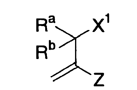
- (2) A method of producing a lithographic printing plate, comprising: ejecting (or discharging) an ink composition for inkjet recording onto a hydrophilic substrate, the ink composition comprising a coloring material and a polymerizing compound; and irradiating the ink composition on the hydrophilic substrate to cure the ink composition, so as to form an image.
- (3) The method of producing a lithographic printing plate as described in (2), wherein the polymerizing compound is a compound having a structure represented by formula (I):

- As a result of our intensive studies, it has been found that the use of a compound having a structure represented by the foregoing formula (I) (hereinafter referred to as "an α-heteromethacrylic compound," too) as a polymerizing compound in an ink composition can provide improvements in ejectability, particle-shape retainability and curability of the ink composition. Many of the α-heteromethacrylic compounds have melting points near to room temperature and self-cohesive properties as to cause gradual crystallization, so they can jet out smoothly at ejection time, and after ejection they can have satisfactory particle-shape retaining properties (crush resistance, no spread on a recording material, no absorption into a recording material).
- In addition, the α-heteromethacrylic compounds used in the invention have properties of being highly polymerizable and resistant to inhibition of polymerization by oxygen, compared with the acrylic compounds as disclosed in JP-A-2003-192943.
- Therefore, high degrees of curing are attained when the present compounds are irradiated with ultraviolet light and electron beams, and the curability becomes remarkable especially in the ultraviolet curing performed in the atmosphere.
- According to an exemplary embodiment of the present method for producing a lithographic printing plate, the present inkjet recording ink composition is used, so the cured strength of image part is heightened, and besides, the adhesion of the image part to a substrate becomes strong, compared with those currently in use. As a reason why such effects are produced, it is supposed that the self-cohesive force of the α-heteromethacrylic compound used comes into play after curing to enhance the cured strength and cause highly chemical interaction, such as chelation, between the α-heteromethacrylic compound molecules and atoms present at the substrate surface to result in enhancement of adhesion to the substrate.
- Further, the α-heteromethacrylic compounds are less prone to being thermally polymerized in the absence of a polymerization initiator than acrylic compounds, so they are superior in storage stability.
- Therefore, the invention can provide an inkjet recording ink composition that is highly sensitive to radiation exposure, can form images of high quality and has satisfactory storage stability, and a method of making a lithographic printing plate requiring no development-processing, having high impression capacity and ensuring high-quality image formation.
- An exemplary embodiment will now be described below.
- The present ink composition can be cured upon irradiation exposure, and contains a coloring material and a polymerizing compound having a specific structure. The term "radiation" as used in the invention has a broad meaning, and is intended to include α-rays, γ-rays, X-rays, ultraviolet rays, visible rays and electron beams. However, the invention aims at providing ink compositions suitable for curing upon irradiation with ultraviolet rays and electron beams, especially ultraviolet rays.
- The distinctive compounds in the invention are compounds which each have a structure represented by formula (I) and contain at least one polymerizing group. The structure represented by formula (I) may form a substituent with a valence of 1, 2 or more, or it may form a compound on its own by allowing all of Ra, Rb, X1 and X2 in formula (I) to represent terminal groups. When the structure represented by formula (I) forms a substituent with a valence of 1, 2 or more, at least one of the groups Ra, Rb, X1 and X2 in formula (I) has at least one bonding hand. Further, either X1 or X2 may be a linkage group having n linkable sites (n: an integer of 2 or more); wherein the linkage group may be linked with n substituents represented by formula (I) at its terminals (to form a polymer).
- Alternatively, the structure represented by formula (I) may be attached to a polymer chain via at least one of X1 and X2. In other words, the structure may take the form of being present in some side chains of a polymer chain. Examples of such a polymer chain include linear organic high polymers. More specifically, polyurethane, novolak, vinyl polymers including polyvinyl alcohol, poly(hydroxystyrene), polystyrene, poly(meth)acrylate, poly(meth)acrylamide and polyacetal are included in those linear organic high polymers. These polymers may be homopolymers or copolymers.
- In formula (I), X1 represents a group bonded to the α-carbon via a hetero atom, or a halogen atom, and X2 represents a group bonded to the carbonyl group via a hetero atom, or a halogen atom. Those groups may be terminal groups, or they may be linkage groups and linked with other substituents (including the structure of formula (I) and polymer chains as mentioned above). The hetero atom is preferably a nonmetal atom, with examples including an oxygen atom, a sulfur atom, a nitrogen atom and a phosphorus atom. Examples of a halogen atom include a chlorine atom, a bromine atom, an iodine atom and a fluorine atom. Examples of a group suitable as X1 representing a group bonded to α-carbon via a hetero atom include a hydroxyl group, a substituted oxy group, a mercapto group, a substituted thio group, an amino group, a substituted amino group, a sulfo group, a sulfonato group, a substituted sulfinyl group, a substituted sulfonyl group, a phosphono group, a substituted phosophono group, a phosphonato group, a substituted phosphonato group, a nitro group and a heterocyclic group (linked via the hetero atom). Examples of a group suitable as X2 representing a group bonded to carbonyl group via a hetero atom include a hydroxyl group, a substituted oxy group, a mercapto group, a substituted thio group, an amino group, a substituted amino group and a heterocyclic group.
- Alternatively, X1 and X2 may combine with each other to form a ring structure.
- Ra and Rb independently represent a hydrogen atom, a halogen atom, a cyano group or an organic group. Examples of such an organic group include a hydrocarbon group which may have a substituent and may contain an unsaturated bond, a substituted oxy group, a substituted thio group, a substituted amino group, a substituted carbonyl group and a carboxylato group. Alternatively, Ra and Rb may combine with each other to from a ring structure.
- Examples of each of the groups or substituents recited above with respect to X1, X2, Ra and Rb in formula (I) are described below.
- Examples of the hydrocarbon group that may have a substituent and may contain an unsaturated bond include an alkyl group, a substituted alkyl group, an aryl group, a substituted aryl group, an alkenyl group, a substituted alkenyl group, an alkynyl group and a substituted alkynyl group.
- The alkyl group is a linear, branched or cyclic alkyl group containing 1 to 20 carbon atoms. Examples of such an alkyl group include a methyl group, an ethyl group, a propyl group, a butyl group, a pentyl group, a hexyl group, a heptyl group, an octyl group, a nonyl group, a decyl group, an undecyl group, a dodecyl group, a tridecyl group, a hexadecyl group, an octadecyl group, an eicosyl group, an isopropyl group, an isobutyl group, a s-butyl group, a t-butyl group, an isopentyl group, a neopentyl group, a 1-methylbutyl group, an isohexyl group, a 2-ethylhexyl group, 2-methylhexyl group, a cyclohexyl group, a cyclopentyl group and a 2-norbornyl group. Of these groups, the 1-12C linear alkyl groups, the 3-12C branched alkyl groups and the 5-10C cycloalkyl groups are preferred over the others.
- The substituted alkyl group is made up by combination of an alkylene group with a substituent, and the substituent used herein is a monovalent nonmetallic radical other than hydrogen. Suitable examples of such a radical include halogen radicals (-F, -Br, -Cl, -I), a hydroxyl group, an alkoxy group, an aryloxy group, a mercapto group, an alkylthio group, an arylthio group, an alkyldithio group, an aryldithio group, an amino group, an N-alkylamino group, an N,N-dialkylamino group, an N-arylamino group, an N,N-diarylamino group, an N-alkyl-N-arylamino group, an acyloxy group, a carbamoyloxy group, an N-alkylcarbamoyloxy group, an N-arylcarbamoyloxy group, an N,N-dialkylcarbamoyloxy group, an N,N-diarylcarbamoyloxy group, an N-alkyl-N-arylcarbamoyloxy group, an alkylsulfoxy group, an arylsulfoxy group, an acylthio group, an acylamino group, an N-alkylacylamino group, an N-arylacylamino group, an ureido group, an N'-alkylureido group, an N',N'-dialkylureido group, an N'-arylureido group, an N',N'-diarylureido group, an N'-alkyl-N'-arylureido group, an N-alkylureido group, an N-arylureido group, N'-alkyl-N-alkylureido group, an N'-alkyl-N-arylureido group, an N',N'-dialkyl-N-alkylureido group, an N',N'-dialkyl-N-arylureido group, an N'-aryl-N-alkylureido group, N'-aryl-N-arylureido group, an N',N'-diaryl-N-alkylureido group, an N',N'-diaryl-N-arylureido group, N'-alkyl-N'-aryl-N-alkylureido group, an N'-alkyl-N'-aryl-N-arylureido group, an alkoxycarbonylamino group, an aryloxycarbonylamino group, an N-alkyl-N-alkoxycarbonylamino group, an N-alkyl-N-aryloxycarbonylamino group, an N-aryl-N-alkoxycarbonylamino group, an N-aryl-N-aryloxycarbonylamino group, a formyl group, an acyl group, a carboxyl group and a conjugate base group thereof (hereinafter referred to as "a carboxylato group"), an alkoxycarbonyl group, an aryloxycarbonyl group, a carbamoyl group, an N-alkylcarbamoyl group, an N,N-dialkylcarbamoyl group, an N-arylcarbamoyl group, an N,N-diarylcarbamoyl group, an N-alkyl-N-arylcarbamoyl group, an alkylsulfinyl group, an arylsulfinyl group, an alkylsulfonyl group, an arylsulfonyl group, a sulfo group (-SO3H) and a conjugate base group thereof (hereinafter referred to as "a sulfonato group"), an alkoxysulfonyl group, an aryloxysulfonyl group, a sulfinamoyl group, an N-alkylsulfinamoyl group, an N,N-dialkylsulfinamoyl group, an N-arylsulfinamoyl group, an N,N-diarylsulfinamoyl group, an N-alkyl-N-arylsulfinamoyl group, a sulfamoyl group, an N-alkylsulfamoyl group, an N,N-dialkylsulfamoyl group, an N-arylsulfamoyl group, an N,N-diarylsulfamoyl group, an N-alkyl-N-arylsulfamoyl group, an N-acylsulfamoyl group and a conjugate base group thereof, an N-alkylsulfonylsulfamoyl group (-SO2NHSO2(alkyl)) and a conjugate base group thereof, an N-arylsulfonylsulfamoyl group (-SO2NHSO2(aryl)) and a conjugate base group thereof, an N-alkylsulfonylcarbamoyl group (-CONHSO2(alkyl)) and a conjugate base group thereof, an N-arylsulfonylcarbamoyl group (-CONHSO2(aryl)) and a conjugate base group thereof, an alkoxysilyl group (-Si(O-alkyl)3), an aryloxysilyl group (-Si(O-aryl)3), a hydroxysilyl group (-Si(OH)3) and a conjugate base group thereof, a phosphono group (-PO3H2) and a conjugate base group thereof (hereinafter referred to as "a phosphonato group"), a dialkylphosphono group, -PO3(alkyl)2), a diarylphosphono group (-PO3(aryl)2), an alkylarylphosphono group (-PO3(alkyl)(aryl)), a monoalkylphosphono group (-PO3H(alkyl)) and a conjugate base group thereof (hereinafter referred to as " an alkylphosphonato group"), a monoarylphosphono group (-PO3H(aryl)) and a conjugate base group thereof (hereinafter referred to as "an arylphosphonato group), a dialkylphosphonoxy group (-OPO3(alkyl)2), a diarylphosphonoxy group (-OPO3(aryl)2), an alkylarylphosphonoxy group (-OPO3(alkyl)(aryl)), a monoalkylphosphonoxy group (-OPO3H(alkyl)) and a conjugate base group thereof (hereinafter referred to as "an alkylphosphonatoxy group), a monoarylphosphonatoxy group (-OPO3H(aryl)) and a conjugate base group thereof (hereinafter referred to as "an arylphosphonatoxy group), a cyano group, a nitro group, an aryl group, an alkenyl group and an alkynyl group.
- Examples of the alkyl moieties in those substituents include the alkyl groups as recited above. And examples of the aryl moieties in those substituents include a phenyl group, a biphenyl group, a naphthyl group, a tolyl group, a xylyl group, a mesityl group, a cumenyl group, a fluorophenyl group, a chlorophenyl group, a bromophenyl group, a chloromethylphenyl group, a hydroxyphenyl group, a methoxyphenyl group, an ethoxyphenyl group, a phenoxyphenyl group, an acetoxyphenyl group, a benzoyloxyphenyl group, a methylthiophenyl group, a phenylthiophenyl group, a methylaminophenyl group, a dimethylaminophenyl group, an acetylaminophenyl group, a carboxyphenyl group, a methoxycarbonylphenyl group, an ethoxycarbonylphenyl group, a phenoxycarbonylphenyl group, an N-phenylcarbamoylphenyl group, a phenyl group, a nitrophenyl group, a cyanophenyl group, a sulfophenyl group, a sulfonatophenyl group, a phosphonophenyl group and a phosphonatophenyl group. Examples of an alkenyl group as the foregoing substituent include a vinyl group, a 1-propenyl group, a 1-butenyl grup, a cinnamyl group and a 2-chloro-1-ethenyl group, and those of an alkynyl group as the foregoing substituent include an ethynyl group, a 1-propynyl group, a 1-butynyl group, a trimethylsilylethynyl group and a phenylethynyl group.
- The acyl moieties in the substituents recited above are represented by R4CO-, and examples of R4 herein include a hydrogen atom and the alkyl, aryl, alkenyl and alkynyl groups as recited above. On the other hand, the alkylene moiety in the substituted alkyl group may be a divalent organic group derived from a 1-20C alkyl group by removal of any one hydrogen atom, which is preferably a 1-12C linear, 3-12C branched or 5-10C cyclic alkylene group. Suitable examples of the substituted alkyl group include a chloromethyl group, a bromomethyl group, a 2-chloroethyl group, a trifluoromethyl group, a methoxymethyl group, a methoxyethoxyethyl group, an allyloxymethyl group, a phenoxymethyl group, a methylthiomethyl group, a tolylthiomethyl group, an ethylaminoethyl group, a diethylaminopropyl group, a mopholinopropyl group, an acetyloxymethyl group, a benzoyloxymethyl group, an N-cyclohexylcarbamoyloxyethyl group, an N-phenylcarbamoyloxyethyl group, an acetylaminoethyl group, an N-methylbenzoylaminopropyl group, a 2-oxoethyl group, a 2-oxopropyl group, a carboxypropyl group, a methoxycarbonylethyl group, a methoxycarbonylmethyl group, a methoxycarbonylbutyl group, an ethoxycarbonylmethyl group, a butoxycarbonylmethyl group, an allyloxycarbonylmethyl group, a benzyloxycarbonylmethyl group, a methoxycarbonylphenylmethyl group, a trichloromethylcarbonylmethyl group, an allyloxycarbonylbutyl group, a chlorophenoxycarbonylmethyl group, a carbamoylmethyl group, an N-methylcarbamoylethyl group, an N,N-dipropylcarbamoylmethyl group, an N-(methoxyphenyl)carbamoylethyl group, an N-methyl-N-(sulfophenyl)carbamoylmethyl group, a sulfopropyl group, a sulfobutyl group, a sulfonatobutyl group, a sulfamoylbutyl group, an N-ethylsulfamoylmethyl group, an N,N-dipropylsulfamoylpropyl group, an N-tolylsulfamoylpropyl group, an N-methyl-N-(phosphonophenyl)sulfamoyloctyl group, a phosphonobutyl group, a phosphonatohexyl group, a diethylphosphonobutyl group, a diphenylphosphonopropyl group, a methylphosphonobutyl group, a methylphosphonatobutyl group, a triphosphonohexyl group, a tolylphosphonatohexyl group, a phosphonoxypropyl group, a phosphonatoxybutyl group, a benzyl group, a phenethyl group, an α-methylbenzyl group, a 1-methyl-1-phenylethyl group, a p-methylbenzyl group, a cinnamyl group, an allyl group, a 2-propenylmethyl group, a 2-butenyl group, a 2-methylallyl group, a 2-methylpropenylmethyl group, a 2-propynyl group, a 2-butynyl group, a 3-butynyl group and the groups illustrated below:

- The aryl group can be a group derived from a benzene ring, a ring formed by fusing two or three benzene rings together, or a ring formed by fusing a 5-membered unsaturated ring with at least one benzene ring, with examples including a phenyl group, a naphthyl group, an anthryl group, a phenanthryl group, an indenyl group, an acenaphthenyl group and a fluorenyl group. Of these aryl groups, a phenyl group and a naphthyl group are preferred over the others.
- The substituted aryl group is an aryl group to which a substituent is attached, specifically a group having a monovalent nonmetallic radical, other than hydrogen, as a substituent on a carbon atom forming a ring of the aryl group as recited above. Suitable examples of such a substituent include the alkyl and substituted alkyl groups and the substituents included in the substituted alkyl groups as recited above. And suitable examples of such a substituted aryl group include a biphenyl group, a tolyl group, a xylyl group, a mesityl group, a cumenyl group, a chlorophenyl group, a bromophenyl group, a fluorophenyl group, a chloromethylphenyl group, a trifluromethylphenyl group, a hydroxyphenyl group, a methoxyphenyl group, a methoxyethoxyphenyl group, an allyloxyphenyl group, a phenoxyphenyl group, a methylthiophenyl group, a tolylthiophenyl group, a phenylthiophenyl group, an ethylaminophenyl group, a diethylaminophenyl group, a morpholinophenyl group, an acetyloxyphenyl group, a benzoyloxyphenyl group, an N-cyclohexylcarbamoyloxyphenyl group, an N-phenylcarbamoyloxyphenyl group, an acetylaminophenyl group, an N-methylbenzoylaminophenyl group, a carboxyphenyl group, a methoxycarbonylphenyl group, an allyloxycarbonylphenyl group, a chlorophenoxycarbonylphenyl group, a carbamoylphenyl group, an N-methylcarbamoylphenyl group, an N,N-dipropylcarbamoylphenyl group, an N-(methoxyphenyl)carbamoylphenyl group, an N-methyl-N-(sulfophenyl)carbamoylphenyl group, a sulfophenyl group, a sulfonatophenyl group, a sulfamoylphenyl group, an N-ethylsulfamoylphenyl group, an N,N-dipropylsulfamoylphenyl group, an N-tolylsulfamoylphenyl group, an N-methyl-N-(phosphonophenyl)sulfamoylphenyl group, a phosphonophenyl group, a phosphonatophenyl group, a diethylphosphonophenyl group, a diphenylphosphonophenyl group, a methylphosphonophenyl group, a methylphosphonatophenyl group, a tolylphosphonophenyl group, a tolylphosphonatophenyl group, an allylphenyl group, a 1-propenylmethylphenyl group, a 2-butenylphenyl group, a 2-methylallylphenyl group, a 2-methylpropenylphenyl group, a 2-propynylphenyl group, a 2-butynylphenyl group and 3-butynylphenyl group.
- The alkenyl group can be any of the alkenyl groups as recited above. The substituted alkenyl group is an alkenyl group to which a substituent is attached by being substituted for a hydrogen atom of the alkenyl group. The substituent usable herein includes the substituents in the substituted alkyl groups as recited above, while the alkenyl group usable herein includes the alkenyl groups as recited above. Suitable examples of such a substituted alkenyl group include the groups illustrated below.

- The alkynyl group can be any of the alkynyl groups as recited above. The substituted alkynyl group is an alkynyl group to which a substituent is attached by being substituted for a hydrogen atom of the alkynyl group. The substituent usable herein includes the substituents in the substituted alkyl groups as recited above, while the alkynyl group usable herein includes the alkynyl groups as recited above.
- The term "heterocyclic group" is intended to include a monovalent group derived from a hetero ring by removal of one hydrogen atom and a monovalent group formed by further removing one hydrogen atom from the hetero ring and attaching thereto a substituent as included in those of the substituted alkyl groups recited above (a substituted heterocyclic group). Suitable examples of such a hetero ring are illustrated below:








- The substituted oxy group is represented by R5O-, and as the R5 can be used a monovalent nonmetallic radical other than hydrogen. Suitable examples of such a substituted oxy group include an alkoxy group, an aryloxy group, an acyloxy group, a carbamoyloxy group, an N-alkylcarbamoyloxy group, an N-arylcarbamoyloxy group, an N,N-dialkylcarbamoyloxy group, an N,N-diarylcarbamoyloxy group, an N-alkyl-N-arylcarbamoyloxy group, an alkylsulfoxy group, an arylsulfoxy group, a phosphonoxy group and a phosphonatoxy group. Examples of the alkyl or aryl moieties in those groups include the alkyl and substituted alkyl groups as recited above or the aryl and substituted aryl groups as recited above, respectively. The acyl moiety in the acyloxy group is represented by R6CO-, and examples of the R6 include the alkyl, substituted alkyl, aryl and substituted aryl groups as recited above. Of those substituents, alkoxy, aryloxy, acyloxy and arylsulfoxy groups are preferred over the others. Suitable examples of the substituted oxy group include a methoxy group, an ethoxy group, a propoxy group, an isopropyloxy group, a butyloxy group, a pentyloxy group, a hexyloxy group, a dodecyloxy group, a benzyloxy group, an allyloxy group, a phenethyloxy group, a carboxyethyloxy group, a methoxycarbonylethyloxy group, an ethoxycarbonylethyloxy group, a methoxyethoxy group, a phenoxyethoxy group, a methoxyethoxyethoxy group, an ethoxyethoxyethoxy group, a morpholinoethoxy group, a morpholinopropyloxy group, an allyloxyethoxyethoxy group, a phenoxy group, a tolyloxy group, a xylyloxy group, a mesityloxy group, a cumenyloxy group, a methoxyphenyloxy group, an ethoxyphenyloxy group, a chlorophenyloxy group, a bromophenyloxy group, an acetyloxy group, a benzoyloxy group, a naphthyloxy group, a phenylsulfonyloxy group, a phosphonoxy group and a phosphonatoxy group.
- The substituted thio group is represented by R7S-, and as the R7 can be used a monovalent nonmetallic radical other than hydrogen. Suitable examples of such a substituted thio group include an alkylthio group, an arylthio group, an alkyldithio group, an aryldithio group and an acylthio group. The alkyl or aryl moieties in those groups include the alkyl and substituted alkyl groups as recited above or the aryl and substituted aryl groups as recited above, respectively. The acyl moiety in the acylthio group is represented by R6CO-, and herein the R6 has the same examples as recited above. Of these substituted thio groups, alkylthio and arylthio groups are preferred over the others. Suitable examples of such substituted thio groups include a methylthio group, an ethylthio group, a phenylthio group, an ethoxyethylthio group, a carboxyethylthio group and a methoxycarbonylthio group.
- The substituted amino group is represented by R8NH- or (R9)(R10)N-, and as R8, R9 and R10 each can be used a monovalent nonmetallic radical other than hydrogen. Suitable examples of such substituted amino groups include an N-alkylamino group, an N,N-dialkylamino group, an N-arylamino group, an N,N-diarylamino group, an N-alkyl-N-arylamino group, an acylamino group, an N-alkylacylamino group, an N-arylacylamino group, an ureido group, an N'-alkylureido group, an N',N'-dialkylureido group, an N'-arylureido group, an N',N'-diarylureido group, an N'-alkyl-N'-arylureido group, an N-alkylureido group, an N-arylureido group, an N'-alkyl-N-alkylureido group, an N'-alkyl-N-arylureido group, an N',N'-dialkyl-N-alkylureido group, an N',N'-dialkyl-N-arylureido group, an N'-aryl-N-alkylureido group, an N'-aryl-N-arylureido group, an N',N'-diaryl-N-alkylureido group, an N',N'-diaryl-N-arylureido group, an N'-alkyl-N'-aryl-N-alkylureido group, an N'-alkyl-N'-aryl-N-arylureido group, an alkoxycarbonylamino group, an aryloxycarbonylamino group, an N-alkyl-N-alkoxycarbonylamino group, an N-alkyl-N-aryloxycarbonylamino group, an N-aryl-N-alkoxycarbonylamino group and an N-aryl-N-aryloxycarbonylamino group. The alkyl or aryl moieties in these groups include the alkyl and substituted alkyl groups as recited above or the aryl and substituted aryl groups as recited above, respectively. And the acyl moieties in those acylamino, N-alkylacylamino and N-arylacylamino groups are represented by R6CO-, wherein R6 is the same one as mentioned above. Of those substituted amino groups, N-alkylamino, N,N-dialkylamino, N-arylamino and acylamino groups are preferred over the others. Suitable examples of such substituted amino groups include a methylamino group, an ethylamino group, a diethylamino group, a morpholino group, a piperidino group, a pyrrolidino group, a phenylamino group, a benzoylamino group and an acetylamino group.
- The substituted carbonyl group is represented by R11-CO-, and as the R11 can be used a monovalent nonmetallic radical. Suitable examples of such a substituted carbonyl group include a formyl group, an acyl group, a carboxyl group, an alkoxycarbonyl group, an aryloxycarbonyl group, a carbamoyl group, an N-alkylcarbamoyl group, an N,N-dialkylcarbamoyl group, an N-arylcarbamoyl group, an N,N-diarylcarbamoyl group and an N-alkyl-N-arylcarbamoyl group. The alkyl or aryl moieties in these groups include the alkyl and substituted alkyl groups as recited above or the aryl and substituted aryl groups as recited above, respectively. Of those substituted carbonyl groups, formyl, acyl, carboxyl, alkoxycarbonyl, aryloxycarbonyl, carbamoyl, N-alkylcarbamoyl, N,N-dialkylcarbamoyl and N-arylcarbamoyl groups are preferred over the others. Of these groups, formyl, acyl, alkoxycarbonyl and aryloxycarbonyl groups are preferred by far. More specifically, a formyl group, an acetyl group, a benzoyl group, a carboxyl group, a methoxycarbonyl group, an allyloxycarbonyl group, an N-methylcarbamoyl group, an N-phenylcarbamoyl group, an N,N-diethylcarbamoyl group and a morpholinocarbonyl group are suitable as the substituted carbonyl groups mentioned above.
- The substituted sulfinyl group is represented by R12-SO-, and as the R12 can be used a monovalent nonmetallic radical. Suitable examples of such a substituted sulfinyl group include an alkylsulfinyl group, an arylsulfinyl group, a sulfinamoyl group, an N-alkylsulfinamoyl group, an N,N-dialkylsulfinamoyl group, an N-arylsulfinamoyl group, an N,N-diarylsulfinamoyl group and an N-alkyl-N-arylsulfinamoyl group. The alkyl or aryl moieties in these groups include the alkyl and substituted alkyl groups as recited above or the aryl and substituted aryl groups as recited above, respectively. Of those groups, alkylsulfinyl and arylsulfinyl groups are preferred over the others. Examples of such substituted sulfinyl groups include a hexylsulfinyl group, a benzylsulfinyl group and a tolylsulfinyl group.
- The substituted sulfonyl group is represented by R13-SO2-, and as the R13 can be used a monovalent nonmetallic radical. Preferable examples of such a substituted sulfonyl group include an alkylsulfonyl group and an arylsulfonyl group. The alkyl or aryl moiety of these groups includes the alkyl and substituted alkyl groups as recited above or the aryl and substituted aryl groups as recited above, respectively. Examples of such a substituted sulfonyl group include a butylsulfonyl group and a chlorophenylsulfonyl group.
- The sulfonato group (-SO3 -) is, as mentioned above, the anion moiety of a conjugate base of sulfo group (-SO3H). In general the sulfonato group is preferably used together with a counter cation. Examples of such a counter cation include generally known cations, such as various oniums (e.g., ammoniums, sulfoniums; phosphoniums, iodoniums and aziniums) and metal ions (e.g., Na+, K+, Ca2+, Zn2+).
- The carboxylato group (-CO2 -) is, as mentioned above, the anion moiety of a conjugate base of carboxyl group (-CO2H). In general the carboxylato group is preferably used together with a counter cation. Examples of such a counter cation include generally known cations, such as various oniums (e.g., ammoniums, sulfoniums, phosphoniums, iodoniums and aziniums) and metal ions (e.g., Na+, K+, Ca2+, Zn2+).
- The term "substituted phosphono group" refers to a group formed by subtituting one or two organic oxo groups for one or two hydroxyl groups on phosphono group, and suitable examples of such a group include the dialkylphosphono, diarylphosphono, alkylarylphosphono, monoalkylphosphono and monoarylphosphono groups as mentioned above. Of these groups, the dialkylphosphono and diarylphosphono groups are preferred over the others. Examples of such groups include a diethylphosphono group, a dibutylphosphono group and a diphenylphosphono group.
- The phosphonato group (-PO3 2- or -PO3H-) refers, as mentioned above, to the anion moiety of a conjugate base derived from first- or second-stage acidic dissociation of phosphono group (-PO3H2). In general the phosphonato group is preferably used together with a counter cation. Examples of such a counter cation include generally known cations, such as various oniums (e.g., ammoniums, sulfoniums, phosphoniums, iodoniums and aziniums) and metal ions (e.g., Na+, K+, Ca2+, Zn2+).
- The substituted phosphonato group is the conjugate base anion moiety of a group formed by substituting an organic oxo group for one hydroxyl group in any of the substituted phosphono groups as recited above. Examples thereof include conjugate bases of the monoalkylphosphono (-PO3H(alkyl)) and monoarylphosphono (-PO3H(aryl)) groups as mentioned above. In general these groups are preferably used together with counter cations. Examples of such counter cations include generally known cations, such as various oniums (e.g., ammoniums, sulfoniums, phosphoniums, iodoniums and aziniums) and metal ions (e.g., Na+, K+, Ca2+, Zn2+).
- Examples of a ring structure formed by combining X1 with X2, Ra with Rb, or X1 with Ra or Rb are described below. The ring formed by combining X1 with X2, Ra with Rb, or X1 with Ra or Rb can be a 5-, 6-, 7- or 8-membered aliphatic ring, preferably a 5- or 6-membered aliphatic ring. Such an aliphatic ring may have a substituent on a carbon atom as a constituent of the ring (examples of such a substituent include the substituents of the substituted alkyl groups as recited above), and some of the ring-constituting carbons may be replaced by a hetero atom or hetero atoms (e.g., oxygen, sulfur or/and nitrogen atoms). Further, part of such an aliphatic ring as recited above may form part of an aromatic ring.
- Examples of compounds having the structure represented by formula (I) in the invention are illustrated below, but these examples should not be construed as limiting the scope of the invention in any way.
-


-

-


-


-
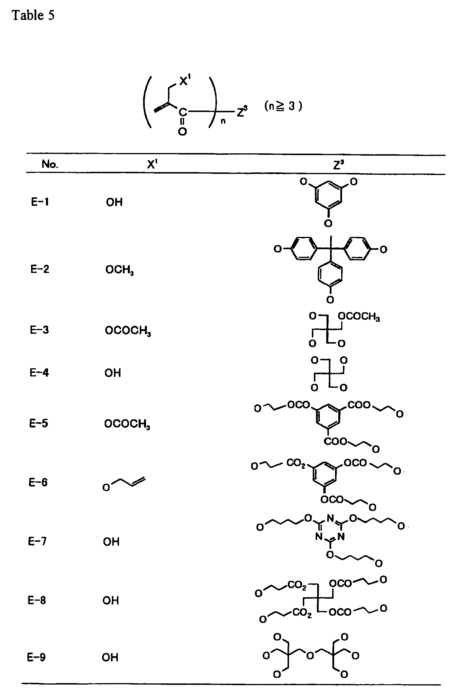


-


-


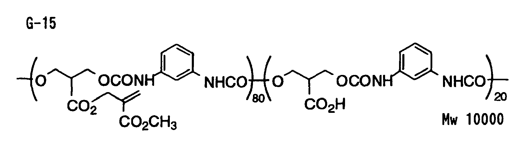


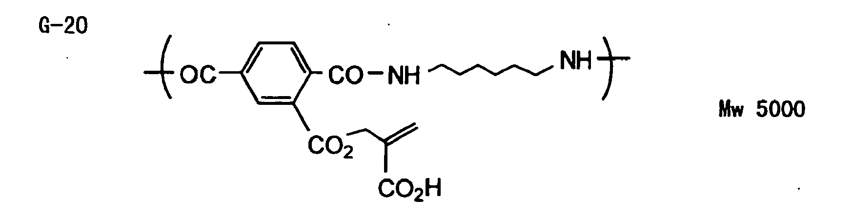


-


-
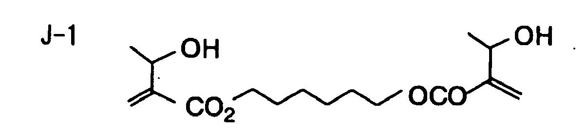


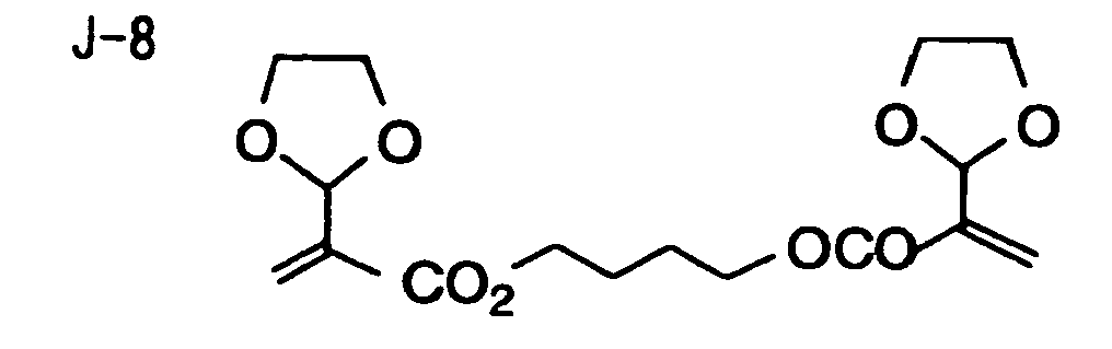


-


-


-


-


- In the present ink composition, α-heteromethacrylic compounds according to the invention are used in an amount of preferably 5 to 95 % by weight, more preferably 15 to 85 % by weight.
- Additionally, polymerizing compounds other than the α-heteromethacrylic compounds as recited above may also be used in the present ink composition. For instance, monoacrylate compounds, multifunctional acrylate monomers and multifunctional acrylate oligomers can be used in combination with the α-heteromethacrylic compounds. Examples of the other polymerizing compounds include isomyristyl acrylate, isostearyl acrylate, lauryl acrylate, isoamyl acrylate, stearyl acrylate, ethoxy-diethylene glycol, methoxy-polyethylene glycol, methoxydipropylene glycol acrylate, 2(2-ethoxyethoxy)ethyl acrylate, butoxyethyl acrylate, isobornyl acrylate, phenoxy-polyethylene glycol acrylate, 2-ethylhexyl-diglycol acrylate, 2-acryloyloxyethyl phthalate, 2-acryloyloxyethyl-2-hydroxyethyl phthalate, ethoxylated phenyl acrylate, 2-acryloyloxyethyl succinate, acrylate of nonyl phenyl-ethylene oxide adduct, 2-acryloyloxyethyl hexahydrophthalate, lactone-modified flexible acrylate, polytetramethylene glycol diacrylate, tetraethylene glycol diacrylate, hydroxypivalic acid neopentyl glycol diacrylate, dimethyloltricyclodecane diacrylate, dimethyloldicyclopentane diarylate, an adduct formed between propylene glycol diglycidyl ether and acrylic acid, an adduct formed between bisphenol A diglycidyl ether and (meth)acrylic acid, modified bisphenol A diacrylates such as bisphenol A-propylene oxide adduct diacrylate and bisphenol A-ethylene oxide adduct diacrylate, glycerol propoxytriacrylate, pentaerythritol tetraacrylate, pentaerythritol ethoxytetraacrylate, dipentaerithritol hexaacrylate, caprolactone-modified dipentaerythritol hexaacrylate, ethylene oxide-modified trimethylolpropane triacrylate, caprolactone-modified trimethylolpropane triacrylate, ditrimethylolpropane tetraacrylatae, amine-modified polyester tetraacrylate, urethane prepolymer prepared from pentaerythritol triacrylate and tolylene diisocyanate, and uretane prepolymer prepared from pentaerythritol triacrylate and hexamethylene diisocyanate. In addition, these polymerizing compounds may be used in combination with other polymerizing monomers or oligomers having molecular weights of 400 or above (e.g., acrylate monomers or oligomers having molecular weights of 400 or above). As to the other polymerizing compounds recited above, it is preferable to use at least one compound selected from isomyristyl acrylate, isostearyl acrylate, lauryl acrylate, isoamyl acrylate, stearyl acrylate, ethoxy-diethylene glycol acrylate, methoxy-polyethylene glycol acrylate, methoxydipropylene glycol acrylate, 2(2-ethoxyethoxy)ethyl acrylate or lactone-modified flexible acrylate.
- In the combined use with the present α-heteromethacrylic compounds, it is appropriate that an amount of the other polymerizing compounds as recited above is preferably 5 to 85 weight %, more preferably 5 to 70 weight %, of all the polymerizing compounds used.
- Coloring materials usable in the invention are described below.
- As to the coloring materials used in the invention, there is no particular restriction. Although pigments superior in weather resistance are preferable, any of known coloring materials including soluble dyes and fat dyes may be used in the invention.
- Pigments that are preferably used in the invention are described. In the present ink composition, it is possible to use pigments not yet in the actual use for inkjet ink because their color formability (color density per concentration of pigments added) is not always high, and besides, they are difficult to make into homogeneous fine-grain dispersions and therefore suffer a phenomenon that their use in high concentrations causes excessive increase in melt viscosity. For instance, the following organic and inorganic pigments having the numbers assigned in Color Index are usable though the invention imposes no particular limitation on pigments to be used.
- Examples of red or magenta pigments include Pigment Red 3, 5, 19, 22, 31, 38, 43, 48:1, 48:2, 48:3, 48:4, 48:5, 49:1, 53:1, 57:1, 57:2, 58:4, 63:1, 81, 81:1, 81:2, 81:3, 81:4, 88, 104, 108, 112, 122, 123, 144, 146, 149, 166, 168, 169, 170, 177, 178, 179, 184, 185, 208, 216, 226 and 257. Examples of violet pigments include Pigment Violet 3, 19, 23, 29, 30, 37, 50 and 88, and those of orange pigments include Pigment Orange 13, 16, 20 and 36. Examples of blue or cyan pigments include Pigment Blue 1, 15, 15:1, 15:2, 15:3, 15:4, 15:6, 16, 17-1, 22, 27, 28, 29, 36 and 60, and those of green pigments include Pigment Green 7, 26, 36 and 50. Examples of yellow pigments include Pigment Yellow 1, 3, 12, 13, 14, 17, 34, 35, 37, 55, 74, 81, 83, 93, 94, 95, 97, 108, 109, 110, 137, 138, 139, 153, 154, 155, 157, 166, 167, 168, 180, 185 and 193. Examples of black pigments include Pigment Black 7, 28 and 26, and those of white pigments include Pigment White 6, 18 and 21. From these pigments, appropriate ones can be selected according to the desired purpose.
- For dispersing pigments can be used various types of dispersing apparatus, such as a ball mill, a sand mill, an attrition mill, a roll mill, an agitation mill, Henschel mixer, a colloid mill, an ultrasonic homogenizer, a pearl mill, a wet jet mill and a paint shaker. In addition, it is possible to add a dispersant on the occasion when pigments are dispersed. The dispersant added has no particular restriction as to its kind, but it is preferable to use a polymeric dispersant. Examples of a polymeric dispersant usable herein include Solsperse Series manufactured by Zeneca Inc. Further, it is also possible to use as dispersing aids a wide variety of synergists appropriate to the pigments used. These dispersants and dispersing aids are preferably added in an amount of 1 to 50 parts by weight per 100 parts by weight of pigments. Although the dispersing medium can be solvents or polymerizing compounds according to the invention, the radiation-curable ink used in the invention prefers containing no solvent because it is required to undergo reaction and be cured immediately after it impacts against a recording material. The solvents remaining in the cured images produce a problem of causing deterioration in solvent resistance and a problem about volatile organic compounds (VOC) therein. From the viewpoint of dispersion suitability, therefore, it is preferable to choose as the dispersing medium a polymerizing compound, especially a monomer having the lowest viscosity, but not a solvent.
- The selection of a pigment, a dispersant and a dispersing medium and the setting of conditions for dispersion and filtration are determined so that the pigment particles preferably have their average size in the range of 0.08 to 0.5 µm and the maximum size in the range of 0.3 to 10 µm, preferably 0.3 to 3 µm. By such a particle-size control, clogging of head nozzles can be prevented and storage stability, transparency and curing sensitivity of the ink can be maintained. Further, it is appropriate that the proportion of a coloring material added in the total ink be from 1 to 10 % by weight, preferably 2 to 8 % by weight.
- In addition to the ingredients mentioned above, the present inkjet recording ink composition can contain other ingredients as required.
- When electron beams or X-rays are used as irradiation light, no polymerization initiator is required. On the other hand, the use of ultraviolet light (UV light), visible light or infrared light as a light source requires addition of radical polymerization initiators, polymerization initiation assistants and sensitizing dyes appropriate to wavelengths of the light source used. As the polymerization initiators, various known compounds can be used, but it is preferable to select them from compounds capable of dissolving the polymerizing compounds relating to the invention. Examples of compounds suitable as polymerization initiators include polymerization initiators of xanthone or thioxanthone type, polymerization initiators of benzophenone type, polymerization initiators of quinone type and polymerization initiators of phosphine oxide type.
- From the viewpoint of enhancing the keeping quality, it is appropriate that 200 to 20,000 ppm of a polymerization inhibitor be further added. Since it is preferable to eject the present inkjet recording ink in a state that the ink is lowered in viscosity by heating at temperatures ranging from 40°C to 80°C, the addition of a polymerization inhibitor is favorable for prevention of head clogging by thermal polymerization. Examples of a polymerization inhibitor usable herein include hydroquinone, benzoquinone, p-methoxyphenol, TEMPO, TEMPOL and cupferron Al.
- In addition, known compounds can be used as required. For instance, surfactants, leveling additives, matting agents, and substances for adjustment of film properties, such as polyester resin, polyurethane resin, vinyl resin, acrylic resin, rubber resin and wax, can be used as appropriate. Moreover, addition of a non-polymerization-inhibiting tackifier is favorable for improvement in adhesiveness to recording materials, such as polyolefin and PET. More specifically, the high-molecular-weight, tacky polymers as disclosed in JP-A-2001-49200, pp. 5-6, including copolymers of 1-20C alkyl group-containing alcohol esters of (meth)acrylic acid, 2-14C alicyclic alcohol esters of (meth)acrylic acid and 6-14C aromatic alcohol esters of (meth)acrylic acid, and low-molecular-weight, tackiness-imparting resins having polymerizing unsaturated bonds can be used as tackifiers.
- In improving adhesiveness to a recording material, it is also effective to add a trace amount of organic solvent. In this case, the addition within the bounds of no problems about solvent resistance and VOC is effective, and the organic solvent content in the whole ink composition is preferably from 0.1 to 5 % by weight, far preferably from 0.1 to 3 % by weight.
- As a hedge against sensitivity drop by the light-shielding effect of coloring materials in ink, conversion to a radical-cation hybrid cure ink by combining a polymerization initiator with a monomer capable of undergoing cationic polymerization and being long in polymerization initiator life is one of preferred embodiments of the present ink composition, too.
- In view of ejectability, it is appropriate that the present ink composition have ink viscosity of 7 to 30 mPa·s, preferably 7 to 20 mPa·s, at the ejection-time temperature. So, it is preferable that the proportions of constituents in the ink composition are determined properly so as to control the ink viscosity to within the forgoing range. Incidentally, the ink viscosity at temperatures ranging from 25°C to 30°C is from 35 to 500 mPa·s, preferably from 35 to 200 mPa·s. By adjusting the ink viscosity at room temperature to a high value, ink permeation into a recording material can be prevented even when the recording material is porous, and thereby reduction in monomer molecules remaining without receiving curing reaction and the control of a bad smell become possible, and besides, the dot spread upon impact of ink droplets against the recording material can be lessened. As a result, image quality can be improved. The ink viscosity lower than 35 mPa·s at 25-30°C produces little effect on prevention of dot spread, while the ink viscosity higher than 50 mPa·s at 25-30°C causes a problem with ink liquid delivery.
- The surface tension of the present ink composition is preferably from 20 to 30 mN/m, far preferably from 23 to 28 mN/m. In the case of recording on various recording materials, such as polyolefin film, PET film, coated paper and uncoated paper, the suitable surface tension is 20 mN/m or above from the viewpoint of ink spread and permeation, but it is 30 mN/m or below from the viewpoint of wettability.
- Substrates usable in the invention are described below.
- The substrates used in the invention are not particularly restricted as to their kinds so long as they are dimensionally stable sheet-form hydrophilic substrates. Examples of a substrate usable in the invention include paper, plastic-laminated paper (such as polyethylene-, polypropylene- or polystyrene-laminated paper), a sheet of metal (e.g., aluminum, zinc, copper), a film of plastic (such as cellulose diacetate, cellulose triacetate, cellulose propionate, cellulose butyrate, cellulose acetate butyrate, cellulose nitrate, polyethylene terephthalate, polyethylene, polystyrene, polypropylene, polycarbonate, polyvinyl acetal), and paper and plastic films on which the metals as recited above are laminated or evaporated. Of these substrates, a polyester film and an aluminum sheet are preferred over the others. In terms of superiority in dimensional stability and moderate price, an aluminum sheet is especially advantageous.
- The aluminum sheet is a pure aluminum sheet, an alloy sheet containing aluminum as a major component and trace amounts of foreign elements, or a thin film of pure aluminum or aluminum alloy on which a plastic is laminated. Examples of foreign elements contained in aluminum alloys include silicon, iron, manganese, copper, magnesium, chromium, zinc, bismuth, nickel and titanium. The content of those foreign metals in aluminum alloy is up to 10 % by weight. Although pure aluminum is preferable in the invention, absolutely pure aluminum is difficult to produce from a technological viewpoint of smelting, so aluminum containing foreign elements in small amounts may be used. The aluminum sheet has no particular restrictions as to the composition thereof, and any of the known materials approved officially can be utilized as appropriate.
- The thickness of the substrate as recited above is preferably from 0.1 to 0.6 mm, far preferably from 0.15 to 0.4 mm.
- Before using such an aluminum sheet, the aluminum sheet is preferably subjected to surface treatments, such as surface-roughening treatment and anodic oxidation treatment. These treatments can render the aluminum sheet surface highly hydrophilic and can make it easy to ensure sufficient adhesion to an image-recording layer. Before undergoing the surface-roughening treatment, the aluminum sheet is subjected to degreasing treatment with a surfactant, an organic solvent or an alkaline aqueous solution for removal of rolling oil from the aluminum sheet surface, if needed.
- The surface-roughening treatment of an aluminum sheet can be carried out using various methods. For instance, mechanical surface-roughening treatment, electrochemical surface-roughening treatment (surface-roughening treatment through electrochemical dissolution of the aluminum sheet surface), or chemical surface-roughening treatment (a method of selectively dissolving the surface through chemical action) can be adopted.
- As the mechanical surface-roughening method, known methods including a ball graining method, a brush graining method, a blast graining method and a buff graining method can be adopted. Alternatively, it is acceptable to adopt a transfer method of using a roll having an uneven surface profile and transferring its unevenness to an aluminum sheet surface at the rolling stage of aluminum.
- As to the electrochemical surface-roughening method, there is a method of roughening the surface of an aluminum sheet in an electrolytic solution containing an acid, such as hydrochloric acid or nitric acid, by passing AC or DC current through the electrolytic solution. In addition, as disclosed in JP-A-54-63902, the electrolytic surface-roughening method using a mixed acid can also be used.
- The thus surface-roughened aluminum sheet is subjected to alkali etching treatment with an aqueous solution of potassium hydroxide or sodium hydroxide and further to neutralizing treatment, if needed, and then to anodic oxidation treatment, if desired for enhancing abrasion resistance.
- As electrolytes used for the anodic oxidation treatment of an aluminum sheet, various electrolytes capable of forming porous oxide coating can be used. In general, sulfuric acid, hydrochloric acid, oxalic acid, chromic acid and mixed acids of two or more thereof can be used as such electrolytes. The suitable electrolyte concentration can be determined properly depending on the kind of an electrolyte used.
- Conditions for anodic oxidation treatment vary with electrolytes used, so they cannot be specified sweepingly. In general, however, it is appropriate that the electrolyte concentration in an electrolytic solution be from 1 to 80 % by weight, the electrolytic solution temperature be from 5 to 70°C, the current-density be from 5 to 60 amperes/dm2, the voltage be from 1 to 100 V, and the electrolysis time be from 10 sec. to 5 min. The suitable quantity of an anodic oxide coating formed is from 1.0 to 5.0 g/m2, particularly from 1.5 to 4.0 g/m2. In such a quantity range, the anodic oxide coating can provide a sufficient press life and a satisfactory scratch resistance in non-image areas of a lithographic printing plate.
- The substrate that has been subjected to the foregoing surface treatments and further provided with an anodic oxide coating may be used in the invention as it is. However, with the intention of further improving adhesion to the upper layer, water wettability, scumming resistance and thermal insulation, such a substrate can undergo an additional treatment chosen appropriately from the treatment for enlarging or sealing micropores of the anodic oxide coating or the treatment for imparting water wettability to the surface by immersion into an aqueous solution of hydrophilic compounds as disclosed in JP-A-2001-253181 and JP-A-2001-322365. It goes without saying that those enlarging and sealing treatments should not be construed as being limited to the treatments disclosed in the documents cited above, but any of known methods can be applied thereto.
- Examples of sealing treatment which can achieve the foregoing intention include steam sealing, treatment with fluorozirconic acid alone, sealing with an aqueous solution containing an inorganic fluorine compound, such as sodium fluoride, sealing with lithium chloride-added steam, and hot water sealing.
- Of these sealing treatments, sealing with an aqueous solution containing an inorganic fluorine compound, steam sealing and hot water sealing are advantageous. Each of these treatments are described below.
- As the inorganic fluorine compound used in sealing treatment with an aqueous solution containing an inorganic fluorine compound, a metal fluoride, for example, is suitable.
- Examples of such an inorganic fluorine compound include sodium fluoride, potassium fluoride, calcium fluoride, magnesium fluoride, sodium fluorozirconate, potassium fluorozirconate, sodium fluorotitanate, potassium fluorotitanate, ammonium fluorozirconate, ammonium fluorotitanate, fluorozirconic acid, fluorotitanic acid, hexafluorosilicic acid, nickel fluoride, iron fluoride, fluorophosphoric acid and ammonium fluorophosphate. Of these compounds, sodium fluorozirconate, sodium fluorotitanate, fluorozirconic acid and fluuorotitanic acid are preferred over the others.
- From the viewpoint of adequately sealing micropores in anodic oxide coating, the inorganic fluorine compound concentration in the aqueous solution is preferably at least 0.01 % by weight, far preferably at least 0.05 % by weight, and in terms of scumming resistance it is preferably at most 1 % by weight, far preferably at most 0.5 % by weight.
- It is preferable that the aqueous solution containing an inorganic fluorine compound further contains a phosphate compound. Addition of a phosphate compound enhances water-receptivity of the surface of an anodic oxide coating, and thereby on-machine developability and scumming resistance can be improved.
- As the phosphate compound, a metal phosphate, such as an alkali metal phosphate or an alkaline earth metal phosphate, is suitable.
- Examples of such a phosphate compound include zinc phosphate, aluminum phosphate, ammonium phosphate, diammonium hydrogen phosphate, ammonium dihydrogen phosphate, monoammonium phosphate, monopotassium phosphate, monosodium phosphate, potassium dihydrogen phosphate, dipotassium hydrogen phosphate, calcium phosphate, ammonium sodium hydrogen phosphate, magnesium hydrogen phosphate, magnesium phosphate, ferrous phosphate, ferric phosphate, sodium dihydrogen phosphate, sodium phosphate, disodium hydrogen phosphate, lead phosphate, diammonium phosphate, calcium dihydrogen phosphate, lithium phosphate, phosphotungstic acid, ammonium phosphotungstate, sodium phosphotungstate, ammonium phosphomolybdate, sodium phosphomolybdate, sodium phosphite, sodium tripolyphosphate and sodium pyrophosphate. Of these phosphate compounds, sodium dihydrogen phosphate, disodium hydrogen phosphate, potassium dihydrogen phosphate and dipotassium hydrogen phosphate are preferred over the others.
- Although no particular restriction is placed on the combination of an inorganic fluorine compound and a phosphate compound, it is preferable that the aqueous solution contains sodium fluorozirconate as the inorganic fluorine compound and at least sodium dihydrogen phosphate as the phosphate compound.
- The suitable phosphate compound concentration in the aqueous solution is at least 0.01 % by weight, preferably at least 0.1 % by weight, from the viewpoint of improvements in on-machine developability and scumming resistance, and it is at most 20 % by weight, preferably at most 5 % by weight, in terms of solubility.
- Although the proportion of each compound in the aqueous solution has no particular limitation, it is preferable that the proportion between an inorganic fluorine compound and a phosphate compound is from 1/200 to 10/1, particularly from 1/30 to 2/1, by weight.
- The suitable temperature of the aqueous solution is 20°C or above, preferably 40°C or above, and besides, it is 100°C or below, preferably 80°C or below.
- The suitable pH of the aqueous solution is 1 or above, preferably 2 or above, and besides, it is 11 or below, preferably 5 or below.
- The sealing with the aqueous solution containing an inorganic fluorine compound has no particular restriction as to the method thereof, but an immersion method and a spray method, for example, can be adopted. Operations in these methods may be performed once or more than once individually, or those methods may be used in combination.
- Of those methods, an immersion method is preferable. When treatment is carried out using the immersion method, the suitable treatment time is 1 second or longer, preferably 3 seconds or longer, and besides, it is 100 seconds or shorter, preferably 20 seconds or shorter.
- Sealing with steam can be achieved according to a method of bringing pressurized or normal-pressure steam into contact with an anodic oxide coating continuously or discontinuously.
- The suitable steam temperature is 80°C or higher, preferably 95°C or higher, and besides, it is 105°C or lower.
- The suitable pressure of the steam is in the range of (atmospheric pressure - 50 mmAq) to (atmospheric pressure + 300 mmAq), or 1.008×10⁵ to 1.043×10⁵ Pa.
- And the suitable duration of contact with steam is at least 1 second, preferably at least 3 seconds, and besides, it is at most 100 seconds, preferably at most 20 seconds.
- Sealing with hot water can be achieved according to a method of immersing an anodic oxide coating-formed aluminum sheet in hot water.
- The hot water may contain an inorganic salt (e.g., a phosphate) or an organic salt.
- The suitable temperature of hot water is 80°C or higher, preferably 95°C or higher, and besides, it is 100°C or lower.
- And the suitable duration of immersion in hot water is at least 1 second, preferably at least 3 seconds, and besides, it is at most 100 seconds, preferably at most 20 seconds.
- As the water-receptivity imparting treatment usable in the invention, there is the alkali metal silicate method as described in each of U.S. Patent Nos. 2,714,066, 3,181,461, 3,280,734 and 3,902,734. In this method, a substrate undergoes immersion or electrolytic treatment in an aqueous solution of, e.g., sodium silicate. In addition, the method of treating with potassium fluorozirconate disclosed in JP-B-36-22063 and the method of treating with polyvinylphosphonic acid as described in each of U.S. Patent Nos. 3,276,868, 4,153,461 and 4,689,272 can be applied.
- It is preferable that the substrate used in the invention has its center-line average roughness in the range of 0.10 to 1.2 µm. In such a roughness range, the substrate can be brought into intimate contact with an image-recording layer and can ensure a sufficient press life and satisfactory scumming resistance.
- Inkjet recording methods and inkjet recording apparatus adopted suitably in the invention are described below.
- In an inkjet recording method, it is preferable that the ink composition as mentioned above is heated up to 40-80°C to lower its viscosity to 7-30 mPa·s, and then forced to jet out. By adopting such a method, high jet consistency can be achieved. Since most of radiation-curable ink compositions generally have higher viscosity than water-based ink, a variance of their viscosity due to variations in temperature during printing becomes greater. Such a viscosity variance of the ink composition directly has great influences on the size and jet speed of liquid-drops and causes deterioration in image quality. Therefore, the ink composition temperature during the printing is required to be kept as constant as possible. The regulation range of ink composition temperature is adjusted preferably to a set temperature ± 5°C, far preferably to a set temperature ± 2°C, particularly preferably to a set temperature ± 1 °C.
- One feature of the inkjet recording apparatus is to have a unit for stabilizing the ink composition temperature, and sections to be kept at a constant temperature include the piping system from an ink tank (or an intermediate tank if it is provided) to the jet front of nozzles and all members installed therein.
- The temperature control, though it has no particular restriction as to the method thereof, is preferably carried out by, e.g., placing more than one temperature sensor at each piping site and regulating the temperature by heating responsive to the flow rate of ink composition and ambient temperature. The head unit to be heated is preferably cut off or insulated from the outside heat so that the unit body is unaffected by outside air temperature. For reduction in startup time required for a printer to be heated or control of thermal energy loss, it is appropriate that the head unit be thermally insulated from other sections, and what is more, the thermal capacity of the heating unit as a whole be lessened.
- Irradiation conditions of radiation are described below. The basic irradiation method is disclosed in JP-A-60-132766. Specifically, a light source is installed on both sides of a head unit, and the head and the light source are made to scan in accordance with a shuttle system. After impact of ink droplets, irradiation is carried out a fixed time interval later. And the curing is completed with another light source accompanied with no drive. In WO 99/54415, the method of using optical fibers and the method of shining a collimated light source on the surface of a mirror mounted on the side of a head unit and irradiating the recording areas with UV light are disclosed. In the invention, those irradiation methods can be used.
- In the invention, it is appropriate that the ink composition is heated to a given temperature and the interval between impact and irradiation is controlled so as to fall within the range of 0.01-0.5 second. And it is preferable by far that the radiation exposure is commenced 0.01 to 0.3 second later, especially 0.01 to 0.15 second later. The control of an interval between impact and irradiation to a very short time makes it possible to prevent the ink having impacted a recording material from spreading before being cured. In addition, such a control also enables the irradiation to be commenced before the ink composition permeates into the radiation-inaccessible depth of a recording material even when the recording material is porous, so the incidence of unreacted monomer residues is curbed to result in reduction of a bad smell. The combined use of the aforementioned inkjet recording method and the present ink composition can produce a great synergistic effect. The great effect can be achieved notably in the case of using the ink composition having its ink viscosity at 25°C in the range of 35-500 MP·s. By adopting such a recording method, the consistent dot size of ink having impacted can be ensured on various recording materials differing in surface wettability, and the image quality can be improved. Additionally, superimposing colors in order of increasing lightness is preferred in forming color images. When the ink of low lightness is superimposed, the irradiation light is hard to reach the ink situated beneath; as a result, it tends to occur that the curing sensitivity is impaired, the monomer residues increase in quantity, the bad smell is emitted and the adhesiveness deteriorates. In terms of cure acceleration, the color-by-color irradiation is preferred though it is also possible that all of colors ejected in jets are exposed to light all together.
- The inkjet recording apparatus used in the invention has no particular restrictions, and it may be commercially available inkjet recording apparatus. In other words, the recording on a recording material by use of commercially available inkjet apparatus is possible in the invention.
- The invention will now be illustrated more specifically by reference to the following examples, but these examples should not be construed as limiting the scope of the invention.
- Dispersion 1 of each of yellow, magenta, cyan and black pigments was prepared in the following manner. Specifically, each pigment was dispersed by use of a known dispersing apparatus under dispersing conditions adjusted properly so as to make the average particle size of the pigment fall within the range of 0.2-0.3 µm, and then the dispersion thus obtained was filtered under heating, thereby preparing the intended Dispersion 1.
(Dispersion 1 of Yellow Pigment) C.I. Pigment Yellow 12 10 parts by weight Polymeric dispersant (Solsperse Series, a product of Zeneca Inc.) 5 parts by weight Stearyl acrylate 85 parts by weight (Dispersion 1 of Magenta Pigment) C.I. Pigment Red 57:1 15 parts by weight Polymeric dispersant (Solsperse Series, a product of Zeneca Inc.) 5 parts by weight Stearyl acrylate 80 parts by weight (Dispersion 1 of Cyan Pigment) C.I. Pigment Blue 15:3 20 parts by weight Polymeric dispersant (Solsperse Series, a product of Zeneca Inc.) 5 parts by weight Stearyl acrylate 75 parts by weight (Dispersion 1 of Black Pigment) C.I. Pigment Black 7 20 parts by weight Polymeric dispersant (Solsperse Series, a product of Zeneca Inc.) 5 parts by weight Stearyl acrylate 75 parts by weight - Ink of each color was prepared using each Dispersion 1 prepared in advance and according to the following method.
(Yellow Ink 1) Dispersion 1 of yellow pigment 20 parts by weight Compound A-86 shown in Table-1 60 parts by weight Compound D-19 shown in Table-4 10 parts by weight Compound F-6 shown in Table-6 5 parts by weight Polymerization initiator 5 parts by weight (IRGACURE 184, produced by Ciba Specialty Chemicals) (Magenta Ink 1) Dispersion 1 of magenta pigment 20 parts by weight Compound A-86 shown in Table-1 60 parts by weight Compound D-19 shown in Table-4 10 parts by weight Compound F-6 shown in Table-6 5 parts by weight Polymerization initiator 5 parts by weight (IRGACURE 184, produced by Ciba Specialty Chemicals) (Cyan Ink 1) Dispersion 1 of cyan pigment 15 parts by weight Compound A-86 shown in Table-1 650 parts by weight Compound D-19 shown in Table-4 10 parts by weight Compound F-6 shown in Table-6 5 parts by weight Polymerization initiator 5 parts by weight (IRGACURE 184, produced by Ciba Specialty Chemicals) (Black Ink 1) Dispersion 1 of black pigment 15 parts by weight Compound A-86 shown in Table-1 65 parts by weight Compound D-19 shown in Table-4 10 parts by weight Compound F-6 shown in Table-6 5 parts by weight Polymerization initiator 5 parts by weight (IRGACURE 184, produced by Ciba Specialty Chemicals) - The thus prepared Ink 1 of each color was passed through a filter with an absolute filtration accuracy of 2 µm to obtain the intended Ink 1 of each color.
- Recording on a recording material was performed using a commercially available inkjet recording apparatus provided with piezo-type inkjet nozzles. The ink-feeding system therein was made up of source tanks, feed piping, feed ink tanks installed immediately in front of an inkjet head, filters and a piezo-type inkjet head, and the section extending from the feed ink tanks to the inkjet head was warmed and protected by a thermal insulator. The temperature sensors were installed in the feed ink tanks and in the vicinity of nozzles of the inkjet head, respectively, and the temperature in the nozzle area was controlled so as to fall within the range of 70°C ± 2°C. The piezo-type inkjet head was actuated so as to eject multiple-size dots of 8 to 30 pl in 720 x 720 dpi resolution. The exposure system, the main scan speed and the jet frequencies were adjusted so that UV-A light was condensed so as to have illuminance of 100 mW/cm2 at the exposed surface and the irradiation therewith commenced after a lapse of 0.1 second from impact of ink droplets against a recording material. In addition, the exposure time was made variable, and exposure light energy was applied. Incidentally, the term "dpi" used in the invention refers to the number of dots per 2.54 cm.
- By using the foregoing ink set with four different colors, the black ink, the cyan ink, the magenta ink and the yellow ink were ejected sequentially in jets in order of mention at ambient temperature of 25°C, and the ink of each color was irradiated with UV light individually. In order to apply energy enough to cure the ink of each color completely and avoid detection of tackiness by touch with fingers, every exposure was carried out so that the total exposure energy per color was adjusted to 300 mJ/cm2. The recording materials used herein were a grained aluminum substrate, a transparent biaxially-stretched polypropylene film having printing suitability obtained by surface treatment, a soft sheet of vinyl chloride, cast-coated paper and commercially available recycled paper. When images of each color were recorded on each of these materials, high-resolution images free of dot spread were obtained. Even in the other case of recording on wood free paper, each ink composition was cured to a sufficient degree and free from a strike-through phenomenon, and besides, there was almost no emission of a bad smell traceable to unreacted monomers. Further, the ink recorded on the film had sufficient flexibility, was not cracked even by bending, and had no-problem in the adhesion test through the peeling of cellophane tape (R).
- Magenta ink of four types 2 to 5 were prepared in the following manners.
(Magenta Ink 2) Dispersion 1 of magenta pigment 20 parts by weight Compound A-3 shown in Table 1 40 parts by weight Difunctional aromatic urethane acrylat illustrated below (molecular weight: 1,500) 10 parts by weight Hexafunctional aliphatic urethane acrylate illustrated (molecular weight: 1,000) below 5 parts by weight Polymerization initiator (IRGACURE 184, produced by Ciba Specialty Chemicals) 5 parts by weight (Magenta Ink 3) Dispersion 1 of magenta pigment 20 parts by weight Compound A-18 shown in Table-1 50 parts by weight Lactone-modified acrylate illustrated below (molecular weight: 458) 20 parts by weight Hexafunctional aliphatic urethane acrylate illustrated below (molecular weight: 1,000) 5 parts by weight Polymerization initiator (IRGACURE 184, produced by Ciba Specialty Chemicals) 5 parts by weight (Magenta Ink 4) Dispersion 2 of magenta pigment 20 parts by weight Compound A-29 shown in Table-1 70 parts by weight Hexafunctional aliphatic urethane acrylate illustrated below (molecular weight: 1,000) 5 parts by weight Polymerization initiator (IRGACURE 184, produced by Ciba Specialty Chemicals) 5 parts by weight - The Dispersion 2 of magenta pigment was prepared in the same manner as the Dispersion 1 of magenta pigment in Example 1, except that isobornyl acrylate was used in place of stearyl acrylate.
(Magenta Ink 5) Dispersion 2 of magenta pigment 20 parts by weight Compound A-47 shown in Table-1 60 parts by weight Tetramethylolmethane triacrylate 15 parts by weight Polymerization initiator (IRGACURE 184, produced by Ciba Specialty Chemicals) 5 parts by weight - Magenta Ink 6 and magenta Ink 7 were prepared in the following manners.
(Magenta Ink 6: Comparative Example 1) Dispersion 3 of magenta pigment 20 parts by weight Triethylene glycol diacrylate 45 parts by weight 1,4-Butanediol diacrylate 30 parts by weight Polymerization initiator (IRGACURE, produced by Ciba Specialty Chemicals) 5 parts by weight - The Dispersion 3 of magenta pigment was prepared in the same manner as the Dispersion 1 of magenta pigment in Example 1, except that triethylene glycol diacrylate was used in place of stearyl acrylate.
(Magenta Ink 7: Comparative Example 2) Dispersion 1 of magenta pigment 20 parts by weight Stearyl acrylate 60 parts by weight Difunctional aromatic urethane acrylate illustrated below (molecular weight: 1,500) 10 parts by weight Hexafunctional aliphatic urethane acrylate illustrated below (molecular weight: 1,000) 5 parts by weight Polymerization initiator (IRGACURE 184, produced by Ciba Specialty Chemicals) 5 parts by weight -


- Hexafunctional aliphatic urethane acrylate:
OCN-(CH2)6-NCO/HO-(CH2)4-OH
condensate (Mw:1,500) the end of which is capped with: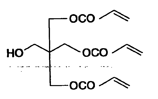
-

- The ink compositions prepared in Examples and Comparative Examples was found to have their ink viscosity within the range of 7 to 20 mPa·s at the injection temperature.
- Magenta images were printed using the thus prepared Magenta Ink 2 to 7 and Magenta Ink 1 prepared in Example 1, respectively, in accordance with the method as described in Example 1.
- The images printed with each of the magenta ink compositions were examined for sensitivity required for curing, permeability into commercially available recycled paper, ink spread on a grained aluminum substrate, adhesion to a grained aluminum substrate, press life and storage stability in accordance with the following methods, respectively.
- The sensitivity to curing was defined as the amount of light exposure energy (mJ/cm2) required for disappearance of a tacky feel from each image surface by UV irradiation. The smaller energy value indicates that the ink used has the higher sensitivity to curing.
- The magenta images printed on commercially available recycled paper were examined on their ink permeability, and evaluation thereof was made in accordance with the following criteria.
Excellent: Permeation is negligible and there is no smell of remaining monomers.
Passable : Slight permeation of ink and a faint smell of remaining monomers are perceived.
Failure : Ink completely permeates through paper and a strong smell of remaining monomers is perceived. - The magenta images printed on a grained aluminum substrate were examined on their ink spread, and evaluation thereof was made in accordance with the following criteria.
Excellent: No spread of ink is observed between adjacent dots.
Passable : Slight dot spread is observed.
Failure : Dots are spread and images are obviously blurred. - For adhesion test of the images printed on a grained aluminum substrate in the foregoing manner, two samples per printed surface were prepared. As to one sample, no cuts were made on the printed surface; while the other was prepared by cutting 11 vertical lines and 11 horizontal lines at 1-mm intervals on the printed surface to make 10×10 1-mm square cuts in a grid pattern in accordance with JISK 5400. A cellophane tape was affixed to each printed surface, and then peeled quickly at a 90° angle. After this action, the appearance of the printed image or the grid pattern remaining unpeeled was evaluated according to the following criteria.
Excellent: No exfoliation of printed image is observed at all even in the grid-pattern test.
Passable : A little flakes of ink are observed in the grid-pattern test, but almost no exfoliation is observed so far as the ink-printed surface gets no scratch.
Failure : The printed image is easily peeled away with acellophane tape (R) under both test conditions. - Printing was performed with a Heidel KOR-D machine in which a grained aluminum substrate having thereon images printed with each magenta ink composition in the foregoing manner was mounted as a printing plate. The number of the copies printed until the printing plate came to off was adopted as a measure of press life. And the press lives are shown as relative values (with Example 1 being taken as 100). The greater number means that the ink composition is the longer in press life and the more suitable for platemaking.
- After each ink composition was stored for 3 days under the condition of 75%RH-60°C, the ink viscosity at the ejection temperature was measured. The increment of ink viscosity was expressed in terms of the ratio of ink viscosity after storage to ink viscosity before storage. The case in which the ratio is nearer to 1.0 because of almost no change in viscosity offers the better storage stability. When the ratio goes up to over 1.5, undesirable clogging often occurs at the time of ejection.
- The evaluation results thus obtained are shown in Table A.

- As can be seen from Table A, the ink compositions using the present α-heteromethacrylic compounds have high sensitivity to radiation exposure, can form images of high quality on paper and have satisfactory storage stability, and can ensure long press life and high-quality image formation when they are used for producing printing plate.
- The entire disclosure of each and every foreign patent application from which the benefit of foreign priority has been claimed in the present application is incorporated herein by reference, as if fully set forth herein.
- While the invention has been described in detail and with reference to specific embodiments thereof, it will be apparent to one skilled in the art that various changes and modifications can be made therein without departing from the spirit and scope thereof.
wherein Ra and Rb each independently represent a hydrogen atom, a halogen atom, a cyano group or an organic group; Z represents CN or COX2; X1 represents a halogen atom or a group bonded to α-carbon via a hetero atom; X2 represents a halogen atom or a group bonded to the carbonyl group via a hetero atom; and X1 and X2, Ra and Rb, X1 and Ra, or X1 and Rb may combine with each other to form a ring structure.
Claims (11)
- An ink composition for inkjet recording, capable of being cured upon radiation exposure, which comprises: a coloring material; and a polymerizing compound having a structure represented by formula (I):

- The ink composition for inkjet recording according to claim 1, wherein the organic group is at least one of a hydrocarbon group, a substituted oxy group, a substituted thio group, a substituted amino group, a substituted carbonyl group and a carboxylato group.
- The ink composition for inkjet recording according to claim 1, wherein the group bonded to α-carbon via the hetero atom is at least one of a hydroxyl group, a substituted oxy group, a mercapto group, a substituted thio group, an amino group, a substituted amino group, a sulfo group, a sulfonato group, a substituted sulfinyl group, a substituted sulfonyl group, a phosphono group, a substituted phosophono group, a phosphonato group, a substituted phosphonato group, a nitro group and a heterocyclic group.
- The ink composition for inkjet recording according to claim 1, wherein the group bonded to the carbonyl group via the hetero atom is at least one of a hydroxyl group, a substituted oxy group, a mercapto group, a substituted thio group, an amino group, a substituted amino group and a heterocyclic group.
- The ink composition for inkjet recording according to claim 1, which has the polymerizing compound in an amount of 5 to 95 % by weight.
- The ink composition for inkjet recording according to claim 1, which comprises another polymerizing compound other than the polymerizing compound having the structure represented by formula (I).
- The ink composition for inkjet recording according to claim 6, wherein the polymerizing compound other than the polymerizing compound having the structure represented by formula (I) is at least one of a monoacrylate compound, multifunctional acrylate monomer and a multifunctional acrylate oligomer.
- The ink composition for inkjet recording according to claim 6, which has the polymerizing compound other than the polymerizing compound having the structure represented by formula (I) in an amount of 5 to 85 % by weight of all of polymerizing compounds.
- The ink composition for inkjet recording according to claim 1, which comprises a polymerization initiator.
- A method of producing a lithographic printing plate, comprising:ejecting an ink composition for inkjet recording onto a hydrophilic substrate, the ink composition comprising a coloring material and a polymerizing compound; andirradiating the ink composition on the hydrophilic substrate to cure the ink composition, so as to form an image.
- The method of producing a lithographic printing plate according to claim 10, wherein the polymerizing compound is a compound having a structure represented by formula (I):

wherein Ra and Rb each independently represent a hydrogen atom, a halogen atom; a cyano group or an organic group; Z represents CN or COX2; X1 represents a halogen atom or a group bonded to α-carbon via a hetero atom; X2 represents a halogen atom or a group bonded to the carbonyl group via a hetero atom; and X1 and X2, Ra and Rb, X1 and Ra, or X1 and Rb may combine with each other to form a ring structure.
Applications Claiming Priority (1)
| Application Number | Priority Date | Filing Date | Title |
|---|---|---|---|
| JP2004189415A JP2006008880A (en) | 2004-06-28 | 2004-06-28 | Inkjet recording ink composition and method for making lithographic printing plate using the same |
Publications (3)
| Publication Number | Publication Date |
|---|---|
| EP1612247A2 true EP1612247A2 (en) | 2006-01-04 |
| EP1612247A3 EP1612247A3 (en) | 2006-02-08 |
| EP1612247B1 EP1612247B1 (en) | 2008-04-02 |
Family
ID=34979019
Family Applications (1)
| Application Number | Title | Priority Date | Filing Date |
|---|---|---|---|
| EP20050013723 Expired - Lifetime EP1612247B1 (en) | 2004-06-28 | 2005-06-24 | Ink composition for inkjet recording and method of producing lithographic printing plate using the same |
Country Status (6)
| Country | Link |
|---|---|
| US (1) | US20060004118A1 (en) |
| EP (1) | EP1612247B1 (en) |
| JP (1) | JP2006008880A (en) |
| CN (1) | CN1715343A (en) |
| AT (1) | ATE391155T1 (en) |
| DE (1) | DE602005005741T2 (en) |
Cited By (3)
| Publication number | Priority date | Publication date | Assignee | Title |
|---|---|---|---|---|
| EP1892573A1 (en) * | 2006-08-22 | 2008-02-27 | FUJIFILM Corporation | Photopolymerizable composition comprising fine particles of organic pigment |
| EP2108526A1 (en) | 2008-04-08 | 2009-10-14 | The Goodyear Tire & Rubber Company | Pneumatic tire having an innerliner comprised of butyl rubber and dispersion of ethylene vinyl alcohol polymer |
| WO2014198820A1 (en) * | 2013-06-14 | 2014-12-18 | Agfa Graphics Nv | A lithographic printing plate precursor |
Families Citing this family (16)
| Publication number | Priority date | Publication date | Assignee | Title |
|---|---|---|---|---|
| JP2007154031A (en) * | 2005-12-05 | 2007-06-21 | Fujifilm Corp | Ink composition |
| JP2007231201A (en) * | 2006-03-02 | 2007-09-13 | Fujifilm Corp | Ink composition, inkjet recording method, printed material, method for producing lithographic printing plate, and lithographic printing plate |
| JP2007238647A (en) * | 2006-03-03 | 2007-09-20 | Fujifilm Corp | Curable composition, ink composition, ink jet recording method, printed matter, method for producing lithographic printing plate |
| JP2007254625A (en) * | 2006-03-24 | 2007-10-04 | Fujifilm Corp | Ink composition, inkjet recording method, printed matter, planographic printing plate manufacturing method, and planographic printing plate |
| JP4874719B2 (en) * | 2006-06-19 | 2012-02-15 | 富士フイルム株式会社 | Ink composition, inkjet recording method, lithographic printing plate production method, and lithographic printing plate |
| JP5728044B2 (en) * | 2006-07-03 | 2015-06-03 | 富士フイルム株式会社 | INK COMPOSITION, INKJET RECORDING METHOD, PRINTED MATERIAL, AND METHOD FOR PRODUCING A lithographic printing plate |
| JP5276264B2 (en) * | 2006-07-03 | 2013-08-28 | 富士フイルム株式会社 | INK COMPOSITION, INKJET RECORDING METHOD, PRINTED MATERIAL, AND METHOD FOR PRODUCING A lithographic printing plate |
| JP5189258B2 (en) * | 2006-07-28 | 2013-04-24 | 富士フイルム株式会社 | INK COMPOSITION, INKJET RECORDING METHOD, PRINTED MATERIAL, AND METHOD FOR PRODUCING A lithographic printing plate |
| JP5224699B2 (en) * | 2007-03-01 | 2013-07-03 | 富士フイルム株式会社 | Ink composition, inkjet recording method, printed material, method for producing lithographic printing plate, and lithographic printing plate |
| DE102008063837A1 (en) | 2008-12-19 | 2010-06-24 | Mankiewicz Gebr. & Co. Gmbh & Co Kg | Coating and its production by inkjet printing process |
| US9238745B2 (en) * | 2011-12-16 | 2016-01-19 | Sun Chemical Corporation | Stray light resistance of UV inkjet inks |
| CN103383330B (en) * | 2012-05-04 | 2015-08-26 | 宏启胜精密电子(秦皇岛)有限公司 | The method for making of material cured Tachistoscope system, method of testing and welding resisting layer |
| WO2014198823A1 (en) * | 2013-06-14 | 2014-12-18 | Agfa Graphics Nv | A lithographic printing plate precursor |
| WO2016117169A1 (en) * | 2015-01-21 | 2016-07-28 | オリンパス株式会社 | Endoscope insertion part and endoscope |
| JP7035561B2 (en) * | 2018-01-25 | 2022-03-15 | 東洋インキScホールディングス株式会社 | Active energy ray-curable flexo ink composition and printed matter thereof |
| JP7112207B2 (en) * | 2018-02-20 | 2022-08-03 | 株式会社ミマキエンジニアリング | three-dimensional object |
Family Cites Families (16)
| Publication number | Priority date | Publication date | Assignee | Title |
|---|---|---|---|---|
| JP2542500B2 (en) * | 1986-10-21 | 1996-10-09 | キヤノン株式会社 | Plate making method |
| CA2078361A1 (en) * | 1991-09-17 | 1993-03-18 | Nippon Paint Co., Ltd. | Method for directly making printing plates using ink-jet system |
| JPH05204138A (en) * | 1991-09-17 | 1993-08-13 | Nippon Paint Co Ltd | Direct plate making method using ink jet system |
| IL106899A (en) * | 1993-09-03 | 1995-08-31 | Adler Uri | Method and apparatus for the production of photopolymeric printing plates |
| US5820932A (en) * | 1995-11-30 | 1998-10-13 | Sun Chemical Corporation | Process for the production of lithographic printing plates |
| US5750314A (en) * | 1995-12-05 | 1998-05-12 | Howard A. Fromson | Method for selectively imaging a lithographic printing plate |
| JPH11256085A (en) * | 1998-03-12 | 1999-09-21 | Ricoh Co Ltd | Ink jet recording ink composition and direct plate making method using the same |
| JP4037015B2 (en) * | 1999-09-22 | 2008-01-23 | 富士フイルム株式会社 | Photopolymerizable composition, image forming material and planographic printing plate |
| US6457413B1 (en) * | 2000-05-26 | 2002-10-01 | Agfa-Gevaert | Computer-to-plate by ink jet |
| US6588339B2 (en) * | 2000-06-19 | 2003-07-08 | Fuji Photo Film Co., Ltd. | Plate-making method, plate-making apparatus, computer-to-cylinder type lithographic printing process and computer-to-cylinder type lithographic printing apparatus |
| CN100470365C (en) * | 2001-01-12 | 2009-03-18 | 富士胶片株式会社 | Positive imaging material |
| JP4414607B2 (en) * | 2001-03-14 | 2010-02-10 | 富士フイルム株式会社 | Radical polymerizable compound |
| JP4213876B2 (en) * | 2001-04-13 | 2009-01-21 | 富士フイルム株式会社 | Photosensitive composition and negative planographic printing plate |
| JP2003043692A (en) * | 2001-08-02 | 2003-02-13 | Fuji Photo Film Co Ltd | Photopolymerizable lithographic printing plate |
| JP4235375B2 (en) * | 2001-08-29 | 2009-03-11 | 富士フイルム株式会社 | How to make a printing plate |
| JP2004002616A (en) * | 2002-03-22 | 2004-01-08 | Konica Minolta Holdings Inc | Active energy ray-curative composition, ink composition for ink jet, ink-jet recording method using the same and planographic printing plate |
-
2004
- 2004-06-28 JP JP2004189415A patent/JP2006008880A/en active Pending
-
2005
- 2005-06-22 US US11/157,966 patent/US20060004118A1/en not_active Abandoned
- 2005-06-24 DE DE200560005741 patent/DE602005005741T2/en not_active Expired - Lifetime
- 2005-06-24 AT AT05013723T patent/ATE391155T1/en not_active IP Right Cessation
- 2005-06-24 EP EP20050013723 patent/EP1612247B1/en not_active Expired - Lifetime
- 2005-06-28 CN CNA2005100810391A patent/CN1715343A/en active Pending
Cited By (4)
| Publication number | Priority date | Publication date | Assignee | Title |
|---|---|---|---|---|
| EP1892573A1 (en) * | 2006-08-22 | 2008-02-27 | FUJIFILM Corporation | Photopolymerizable composition comprising fine particles of organic pigment |
| EP2108526A1 (en) | 2008-04-08 | 2009-10-14 | The Goodyear Tire & Rubber Company | Pneumatic tire having an innerliner comprised of butyl rubber and dispersion of ethylene vinyl alcohol polymer |
| WO2014198820A1 (en) * | 2013-06-14 | 2014-12-18 | Agfa Graphics Nv | A lithographic printing plate precursor |
| US9568822B2 (en) | 2013-06-14 | 2017-02-14 | Agfa Graphics Nv | Lithographic printing plate precursor |
Also Published As
| Publication number | Publication date |
|---|---|
| DE602005005741T2 (en) | 2009-04-16 |
| EP1612247A3 (en) | 2006-02-08 |
| JP2006008880A (en) | 2006-01-12 |
| US20060004118A1 (en) | 2006-01-05 |
| EP1612247B1 (en) | 2008-04-02 |
| DE602005005741D1 (en) | 2008-05-15 |
| CN1715343A (en) | 2006-01-04 |
| ATE391155T1 (en) | 2008-04-15 |
Similar Documents
| Publication | Publication Date | Title |
|---|---|---|
| EP1612247B1 (en) | Ink composition for inkjet recording and method of producing lithographic printing plate using the same | |
| EP1657286B1 (en) | Radiation curable ink jet ink, comprising a polymerisation initiation sensitising dye | |
| JP2002275129A (en) | Radical-polymerizable compound | |
| JP2004310000A (en) | Polymerizable composition and lithographic printing original plate using the same | |
| JP4630034B2 (en) | Radiation curable inkjet ink composition and planographic printing plate using the same | |
| DE602004007559T2 (en) | Photosensitive planographic printing plate | |
| JP2006213862A (en) | Ink composition, inkjet recording method, printed matter, method for making lithographic printing plate and the lithographic printing plate | |
| JP2000309174A (en) | Original plate for lithographic printing plate | |
| JP4471101B2 (en) | Planographic printing plate precursor | |
| JP2006160836A (en) | Ink for ink jet recording curable by irradiating with radioactive ray and method for making lithographic printing plate using the same | |
| JP4662762B2 (en) | Ink jet recording ink and planographic printing plate using the same | |
| DE602006000071T2 (en) | Ink composition for ink jet printing method and method of making a lithographic printing plate therewith | |
| JP2005062482A (en) | Polymerizable composition and recording material using the same | |
| JP2004117555A (en) | Photo or thermosetting composition | |
| JP4966514B2 (en) | Ink composition | |
| JP5204371B2 (en) | INK COMPOSITION FOR INKJET RECORDING AND METHOD FOR PRODUCING A lithographic printing plate using this | |
| JP4414797B2 (en) | Polymerizable composition and image recording material using the same | |
| JP2007051196A (en) | Ink composition | |
| JP2006182990A (en) | Ink composition for inkjet recording and method for preparing lithographic printing plate by using it | |
| JP2007084715A (en) | Ink composition | |
| JP4369780B2 (en) | Polymerizable composition and image recording material using the same | |
| JP4864311B2 (en) | Ink jet recording ink curable by radiation irradiation and lithographic printing plate preparation method using the same | |
| JP2006241301A (en) | Ink composition, inkjet recording method, printed article, method for producing planographic printing plate and planographic printing plate | |
| JP2006241382A (en) | Ink composition, inkjet recording method, printed article, planographic printing plate and method for producing the same | |
| JP2005062478A (en) | Polymerizable composition and recording material |
Legal Events
| Date | Code | Title | Description |
|---|---|---|---|
| PUAI | Public reference made under article 153(3) epc to a published international application that has entered the european phase |
Free format text: ORIGINAL CODE: 0009012 |
|
| PUAL | Search report despatched |
Free format text: ORIGINAL CODE: 0009013 |
|
| AK | Designated contracting states |
Kind code of ref document: A2 Designated state(s): AT BE BG CH CY CZ DE DK EE ES FI FR GB GR HU IE IS IT LI LT LU MC NL PL PT RO SE SI SK TR |
|
| AX | Request for extension of the european patent |
Extension state: AL BA HR LV MK YU |
|
| AK | Designated contracting states |
Kind code of ref document: A3 Designated state(s): AT BE BG CH CY CZ DE DK EE ES FI FR GB GR HU IE IS IT LI LT LU MC NL PL PT RO SE SI SK TR |
|
| AX | Request for extension of the european patent |
Extension state: AL BA HR LV MK YU |
|
| 17P | Request for examination filed |
Effective date: 20060519 |
|
| AKX | Designation fees paid |
Designated state(s): AT BE BG CH CY CZ DE DK EE ES FI FR GB GR HU IE IS IT LI LT LU MC NL PL PT RO SE SI SK TR |
|
| RAP1 | Party data changed (applicant data changed or rights of an application transferred) |
Owner name: FUJIFILM CORPORATION |
|
| 17Q | First examination report despatched |
Effective date: 20070320 |
|
| GRAP | Despatch of communication of intention to grant a patent |
Free format text: ORIGINAL CODE: EPIDOSNIGR1 |
|
| GRAS | Grant fee paid |
Free format text: ORIGINAL CODE: EPIDOSNIGR3 |
|
| GRAA | (expected) grant |
Free format text: ORIGINAL CODE: 0009210 |
|
| AK | Designated contracting states |
Kind code of ref document: B1 Designated state(s): AT BE BG CH CY CZ DE DK EE ES FI FR GB GR HU IE IS IT LI LT LU MC NL PL PT RO SE SI SK TR |
|
| REG | Reference to a national code |
Ref country code: GB Ref legal event code: FG4D |
|
| REG | Reference to a national code |
Ref country code: CH Ref legal event code: EP Ref country code: IE Ref legal event code: FG4D |
|
| REF | Corresponds to: |
Ref document number: 602005005741 Country of ref document: DE Date of ref document: 20080515 Kind code of ref document: P |
|
| PG25 | Lapsed in a contracting state [announced via postgrant information from national office to epo] |
Ref country code: SI Free format text: LAPSE BECAUSE OF FAILURE TO SUBMIT A TRANSLATION OF THE DESCRIPTION OR TO PAY THE FEE WITHIN THE PRESCRIBED TIME-LIMIT Effective date: 20080402 |
|
| NLV1 | Nl: lapsed or annulled due to failure to fulfill the requirements of art. 29p and 29m of the patents act | ||
| PG25 | Lapsed in a contracting state [announced via postgrant information from national office to epo] |
Ref country code: PT Free format text: LAPSE BECAUSE OF FAILURE TO SUBMIT A TRANSLATION OF THE DESCRIPTION OR TO PAY THE FEE WITHIN THE PRESCRIBED TIME-LIMIT Effective date: 20080903 Ref country code: BG Free format text: LAPSE BECAUSE OF FAILURE TO SUBMIT A TRANSLATION OF THE DESCRIPTION OR TO PAY THE FEE WITHIN THE PRESCRIBED TIME-LIMIT Effective date: 20080702 Ref country code: ES Free format text: LAPSE BECAUSE OF FAILURE TO SUBMIT A TRANSLATION OF THE DESCRIPTION OR TO PAY THE FEE WITHIN THE PRESCRIBED TIME-LIMIT Effective date: 20080713 Ref country code: NL Free format text: LAPSE BECAUSE OF FAILURE TO SUBMIT A TRANSLATION OF THE DESCRIPTION OR TO PAY THE FEE WITHIN THE PRESCRIBED TIME-LIMIT Effective date: 20080402 Ref country code: FI Free format text: LAPSE BECAUSE OF FAILURE TO SUBMIT A TRANSLATION OF THE DESCRIPTION OR TO PAY THE FEE WITHIN THE PRESCRIBED TIME-LIMIT Effective date: 20080402 |
|
| PG25 | Lapsed in a contracting state [announced via postgrant information from national office to epo] |
Ref country code: AT Free format text: LAPSE BECAUSE OF FAILURE TO SUBMIT A TRANSLATION OF THE DESCRIPTION OR TO PAY THE FEE WITHIN THE PRESCRIBED TIME-LIMIT Effective date: 20080402 Ref country code: PL Free format text: LAPSE BECAUSE OF FAILURE TO SUBMIT A TRANSLATION OF THE DESCRIPTION OR TO PAY THE FEE WITHIN THE PRESCRIBED TIME-LIMIT Effective date: 20080402 |
|
| PG25 | Lapsed in a contracting state [announced via postgrant information from national office to epo] |
Ref country code: IS Free format text: LAPSE BECAUSE OF FAILURE TO SUBMIT A TRANSLATION OF THE DESCRIPTION OR TO PAY THE FEE WITHIN THE PRESCRIBED TIME-LIMIT Effective date: 20080802 |
|
| EN | Fr: translation not filed | ||
| PG25 | Lapsed in a contracting state [announced via postgrant information from national office to epo] |
Ref country code: CZ Free format text: LAPSE BECAUSE OF FAILURE TO SUBMIT A TRANSLATION OF THE DESCRIPTION OR TO PAY THE FEE WITHIN THE PRESCRIBED TIME-LIMIT Effective date: 20080402 Ref country code: LT Free format text: LAPSE BECAUSE OF FAILURE TO SUBMIT A TRANSLATION OF THE DESCRIPTION OR TO PAY THE FEE WITHIN THE PRESCRIBED TIME-LIMIT Effective date: 20080402 Ref country code: SE Free format text: LAPSE BECAUSE OF FAILURE TO SUBMIT A TRANSLATION OF THE DESCRIPTION OR TO PAY THE FEE WITHIN THE PRESCRIBED TIME-LIMIT Effective date: 20080702 Ref country code: DK Free format text: LAPSE BECAUSE OF FAILURE TO SUBMIT A TRANSLATION OF THE DESCRIPTION OR TO PAY THE FEE WITHIN THE PRESCRIBED TIME-LIMIT Effective date: 20080402 Ref country code: MC Free format text: LAPSE BECAUSE OF NON-PAYMENT OF DUE FEES Effective date: 20080630 |
|
| PLBE | No opposition filed within time limit |
Free format text: ORIGINAL CODE: 0009261 |
|
| STAA | Information on the status of an ep patent application or granted ep patent |
Free format text: STATUS: NO OPPOSITION FILED WITHIN TIME LIMIT |
|
| PG25 | Lapsed in a contracting state [announced via postgrant information from national office to epo] |
Ref country code: RO Free format text: LAPSE BECAUSE OF FAILURE TO SUBMIT A TRANSLATION OF THE DESCRIPTION OR TO PAY THE FEE WITHIN THE PRESCRIBED TIME-LIMIT Effective date: 20080402 Ref country code: BE Free format text: LAPSE BECAUSE OF FAILURE TO SUBMIT A TRANSLATION OF THE DESCRIPTION OR TO PAY THE FEE WITHIN THE PRESCRIBED TIME-LIMIT Effective date: 20080402 Ref country code: SK Free format text: LAPSE BECAUSE OF FAILURE TO SUBMIT A TRANSLATION OF THE DESCRIPTION OR TO PAY THE FEE WITHIN THE PRESCRIBED TIME-LIMIT Effective date: 20080402 |
|
| 26N | No opposition filed |
Effective date: 20090106 |
|
| PG25 | Lapsed in a contracting state [announced via postgrant information from national office to epo] |
Ref country code: IE Free format text: LAPSE BECAUSE OF NON-PAYMENT OF DUE FEES Effective date: 20080624 Ref country code: FR Free format text: LAPSE BECAUSE OF FAILURE TO SUBMIT A TRANSLATION OF THE DESCRIPTION OR TO PAY THE FEE WITHIN THE PRESCRIBED TIME-LIMIT Effective date: 20090123 Ref country code: EE Free format text: LAPSE BECAUSE OF FAILURE TO SUBMIT A TRANSLATION OF THE DESCRIPTION OR TO PAY THE FEE WITHIN THE PRESCRIBED TIME-LIMIT Effective date: 20080402 |
|
| PG25 | Lapsed in a contracting state [announced via postgrant information from national office to epo] |
Ref country code: IT Free format text: LAPSE BECAUSE OF FAILURE TO SUBMIT A TRANSLATION OF THE DESCRIPTION OR TO PAY THE FEE WITHIN THE PRESCRIBED TIME-LIMIT Effective date: 20080402 |
|
| PG25 | Lapsed in a contracting state [announced via postgrant information from national office to epo] |
Ref country code: CY Free format text: LAPSE BECAUSE OF FAILURE TO SUBMIT A TRANSLATION OF THE DESCRIPTION OR TO PAY THE FEE WITHIN THE PRESCRIBED TIME-LIMIT Effective date: 20080402 |
|
| REG | Reference to a national code |
Ref country code: CH Ref legal event code: PL |
|
| PG25 | Lapsed in a contracting state [announced via postgrant information from national office to epo] |
Ref country code: LI Free format text: LAPSE BECAUSE OF NON-PAYMENT OF DUE FEES Effective date: 20090630 Ref country code: CH Free format text: LAPSE BECAUSE OF NON-PAYMENT OF DUE FEES Effective date: 20090630 |
|
| PG25 | Lapsed in a contracting state [announced via postgrant information from national office to epo] |
Ref country code: HU Free format text: LAPSE BECAUSE OF FAILURE TO SUBMIT A TRANSLATION OF THE DESCRIPTION OR TO PAY THE FEE WITHIN THE PRESCRIBED TIME-LIMIT Effective date: 20081003 Ref country code: LU Free format text: LAPSE BECAUSE OF NON-PAYMENT OF DUE FEES Effective date: 20080624 |
|
| PG25 | Lapsed in a contracting state [announced via postgrant information from national office to epo] |
Ref country code: TR Free format text: LAPSE BECAUSE OF FAILURE TO SUBMIT A TRANSLATION OF THE DESCRIPTION OR TO PAY THE FEE WITHIN THE PRESCRIBED TIME-LIMIT Effective date: 20080402 |
|
| PG25 | Lapsed in a contracting state [announced via postgrant information from national office to epo] |
Ref country code: GR Free format text: LAPSE BECAUSE OF FAILURE TO SUBMIT A TRANSLATION OF THE DESCRIPTION OR TO PAY THE FEE WITHIN THE PRESCRIBED TIME-LIMIT Effective date: 20080703 |
|
| PGFP | Annual fee paid to national office [announced via postgrant information from national office to epo] |
Ref country code: DE Payment date: 20120620 Year of fee payment: 8 |
|
| PGFP | Annual fee paid to national office [announced via postgrant information from national office to epo] |
Ref country code: GB Payment date: 20120620 Year of fee payment: 8 |
|
| GBPC | Gb: european patent ceased through non-payment of renewal fee |
Effective date: 20130624 |
|
| REG | Reference to a national code |
Ref country code: DE Ref legal event code: R119 Ref document number: 602005005741 Country of ref document: DE Effective date: 20140101 |
|
| PG25 | Lapsed in a contracting state [announced via postgrant information from national office to epo] |
Ref country code: DE Free format text: LAPSE BECAUSE OF NON-PAYMENT OF DUE FEES Effective date: 20140101 Ref country code: GB Free format text: LAPSE BECAUSE OF NON-PAYMENT OF DUE FEES Effective date: 20130624 |