EP1612183B1 - Load lifting device - Google Patents
Load lifting device Download PDFInfo
- Publication number
- EP1612183B1 EP1612183B1 EP05013103A EP05013103A EP1612183B1 EP 1612183 B1 EP1612183 B1 EP 1612183B1 EP 05013103 A EP05013103 A EP 05013103A EP 05013103 A EP05013103 A EP 05013103A EP 1612183 B1 EP1612183 B1 EP 1612183B1
- Authority
- EP
- European Patent Office
- Prior art keywords
- actuator
- cam
- articulated
- lifting
- linkage
- Prior art date
- Legal status (The legal status is an assumption and is not a legal conclusion. Google has not performed a legal analysis and makes no representation as to the accuracy of the status listed.)
- Expired - Lifetime
Links
Images


Classifications
-
- B—PERFORMING OPERATIONS; TRANSPORTING
- B66—HOISTING; LIFTING; HAULING
- B66F—HOISTING, LIFTING, HAULING OR PUSHING, NOT OTHERWISE PROVIDED FOR, e.g. DEVICES WHICH APPLY A LIFTING OR PUSHING FORCE DIRECTLY TO THE SURFACE OF A LOAD
- B66F7/00—Lifting frames, e.g. for lifting vehicles; Platform lifts
- B66F7/06—Lifting frames, e.g. for lifting vehicles; Platform lifts with platforms supported by levers for vertical movement
- B66F7/065—Scissor linkages, i.e. X-configuration
-
- B—PERFORMING OPERATIONS; TRANSPORTING
- B66—HOISTING; LIFTING; HAULING
- B66F—HOISTING, LIFTING, HAULING OR PUSHING, NOT OTHERWISE PROVIDED FOR, e.g. DEVICES WHICH APPLY A LIFTING OR PUSHING FORCE DIRECTLY TO THE SURFACE OF A LOAD
- B66F3/00—Devices, e.g. jacks, adapted for uninterrupted lifting of loads
- B66F3/02—Devices, e.g. jacks, adapted for uninterrupted lifting of loads with racks actuated by pinions
-
- B—PERFORMING OPERATIONS; TRANSPORTING
- B66—HOISTING; LIFTING; HAULING
- B66F—HOISTING, LIFTING, HAULING OR PUSHING, NOT OTHERWISE PROVIDED FOR, e.g. DEVICES WHICH APPLY A LIFTING OR PUSHING FORCE DIRECTLY TO THE SURFACE OF A LOAD
- B66F3/00—Devices, e.g. jacks, adapted for uninterrupted lifting of loads
- B66F3/46—Combinations of several jacks with means for interrelating lifting or lowering movements
Definitions
- the present invention relates to a lifting device of the type comprising:
- the invention relates in particular to a lifting table with a pantograph linkage of the scissors-type.
- pantograph-type lifting tables enable a movable frame (or platform) to be moved from the lowered position to the raised position while keeping it horizontal, even in case of an off-line mass.
- these pantograph-type lifting tables include a fixed base frame, with means for anchoring it to the floor, a movable frame for receiving the articles to be moved and four arms coupled to each other, in a scissors fashion, so as to provide a pantograph-type linkage, which is moved by suitable lifting means.
- the lifting table device is shaped so as to occupy the volume of a parallelepiped defined by the two sides of the movable table, whereas its height varies from a minimum value, when the lifting table is closed (platform in the lowered position) up to a maximum value, when the table is opened (platform in its raised position).
- the pantograph-type lifting tables are particularly useful for automation of large manufacturing processes, also in case of heavy masses to be handled.
- the lifting means may be of many types, depending upon the needs and the required forces; for instance, hydraulic cylinders, electric cylinders, motor and reduction gear units with associated transmissions can be used.
- Pantograph-type lifting tables are highly flexible and can be used both as lifting means, or as presses or as pushing devices.
- Lifting tables however, have a huge drawback, which is implicit in their own way of operating. Indeed, due to the specific configuration of their linkage, at the beginning of the lifting phase, starting from the closed condition of the pantograph linkage, the vertical movement is hindered by a number of unfavourable leverages, so that the force required for lifting is much greater than the weight to be lifted and is variable throughout the entire movement.
- JP 2000 238996 solves the problem only partially, due to the provision of a fixed cam cooperating with a cam-following element carried by the above mentioned connecting element which connects the lifting device to the linkage.
- the arrangement shown in this document is not satisfactory, in particular because the above mentioned connecting element is subjected to a deflecting force during the lifting movement and therefore is not able to transmit the force applied by the actuator with a high efficiency.
- the object of the present invention is that of providing a lifting device of the type indicated at the beginning of the present description which is able to overcome the above mentioned drawbacks of the prior art and which in particular is able to exploit the force applied by the actuator with a great efficiency in order to obtain the lifting movement of the device.
- a further object of the invention is that of providing a device of the above indicated type which has a relatively simple structure.
- the invention provides a lifting device having all the features which have been indicated at the beginning of the present description and further characterised that the above mentioned actuator is articulated to said connecting element around an axis which is always located below the axis of articulation between the connecting element and the articulated arm, in such a way that, when the actuator is activated to cause a lifting movement of the device, the said connecting element acts as a pushing strut subjected substantially to compression between the cam and said articulated arm of the linkage.
- said actuator is arranged so as to operate with a pulling action during lifting of the device, thus causing a raising movement of the cam-following element along the cam.
- the actuator is arranged to operate with a pushing action during lifting of the device.
- the linkage of the device is a scissors-type pantograph, comprising at least two arms articulated to each other according to a X-shape, with two upper ends and two lower ends respectively connected to the upper structure and the lower structure, said upper ends and said lower ends being guided on said upper structure and said lower structure so that they are movable relative to each other along two parallel horizontal directions, the lower end of one of said arms being pivotally connected to the lower structure around a fixed axis.
- Two pairs of articulated arms of the above described type are preferably used, which are parallel to each other and arranged side by side.
- the above mentioned pushing strut has a head articulated to an arm of the pantograph and a foot pivotally connected to said actuator.
- the cam-following element is a roller freely rotatably mounted on the pushing strut.
- the actuator is pivotally connected to the pushing strut around an axis coincident with, or adjacent to, the axis of the cam-following roller.
- a further particularly preferred feature of the invention lies in that the cam cooperating with the cam-following element carried by said pushing strut has a cam surface configured with a profile such as to keep the force required from the actuator substantially constant during the entire lifting stage.
- This feature is particularly important in order to efficiently exploit the actuator.
- the actuator may be of any type, for example it can include an electric motor connected to a screw-and-nut system, preferably of the ball recirculation type, or a unit comprising an electric motor and a rack driven by the electric motor, or also a hydraulic cylinder. In the preferred embodiment, it is constituted by a hoist system of the type using a belt, a chord or a chain.
- reference numeral 1 generally designates a lifting device of the type comprising a scissors-like linkage.
- Device 1 comprises a lower structure 2 and an upper structure 3 in form of a table or platform movable with respect to the lower structure 2 between a raised position, shown in figure 1, and a lowered position, shown in figure 2.
- Table 3 is connected to the base structure 2 by means of a scissors-like linkage 4 which comprises two pairs of arms articulated to each other according to an X-shape and arranged in two vertical, parallel and spaced apart planes.
- Each pair of articulated arms comprises an arm 5 and an arm 6 articulated to each other around a horizontal axis 7.
- the arms 5 of the two pairs of articulated arms are arranged inside the two arms 6, as shown in figure 4.
- Each of the two inner arms 5 has one of its ends articulated to the base structure 2 around an axis 8 which is horizontal and parallel to axis 7, by means of an articulation pin 9, visible in the left lower part of figure 4.
- Each of the outer arms 6, on its turn, has one end articulated to the structure of the platform 3 around an axis 10 parallel to axes 7, 8, by means of an articulation pin 11 carried by the structure of table 3.
- each inner arm 5 opposite to articulation 8 and the end of each outer arm 6 opposite to articulation 10 support rollers 12 and 13 (figure 4) freely rotatable on pins 14, 15 (having axes 12a and 13a) respectively fixed to the arm 5 and the arm 6 and are guided on cooperating tracks 16, 17 carried by the table 3 and the base structure 2. Due to this arrangement, the ends of arms 5, 6 connected to table 3 and the ends of arms 5, 6 connected to the base structure 2 are movable relative to each other along two parallel horizontal planes, so as to ensure that the horizontal arrangement of table 3 is maintained during the entire raising or lowering movement of the table.
- the actuator unit may be of any known type, but in the case of the preferred embodiment shown herein it comprises a hoist device with a belt engaged on pulleys.
- the actuator unit 19 has one end pivotally mounted around an axis 20 parallel to axes 7, 8, 10 on the base structure 2 and the opposite end pivotally connected around an axis 21 to a connecting element 22 which connects the actuator unit 19 to the linkage 4.
- the connecting element 22 has one end articulated around an axis 23 parallel to axes 7, 8, 10 on the inner arms 5 of the two pairs of articulated arms of the linkage 4.
- the articulation pin 24 which is supported by the structure of the connecting element 22 and is rotatably mounted at its ends within the two inner arms 5.
- the connecting element 22 has a fork shape, with a pair of brackets to which there is fixed a pin 25 on which a cam-following roller 26 is freely rotatably mounted.
- the axis of the cam-following roller is coincident with the articulation axis 21 of the actuator unit 19 on the connecting element 22.
- the cam-following roller 26 cooperates with a cam surface 27 of a cam element 28 fixed to the base structure 2.
- the arrangement is such that the cam surface 27 causes a raising movement of the cam-following roller 26 when the distance between this roller 26 and the fixed axis 20 on which the actuator unit 19 is articulated is decreased, by activating the actuator unit 19.
- the axis 21 of articulation of the actuator unit 19 to the connecting element 22 is located below the axis 23 of articulation of the connecting element 22 to the inner arms 5.
- the cam-following roller 26 is compelled to raise along the cam surface 27 and the connecting element 22 acts as a pushing strut, undergoing substantially to compression between the roller 26 and the articulation 23 to the articulated arm 5, so as to transform the pulling force applied by the actuator unit 19 into a force causing lifting of the device.
- the cam-following roller 26 goes down along the cam surface 27 and the device is lowered in a controlled way, the weight of the upper table 3 and the load which may be present thereon being transformed into a compression force acting on the connecting element 22, which again acts as a strut.
- the geometry of the cam surface 27 is predetermined so that the force which the actuator unit 19 must exert is substantially constant along the entire movement of the lifting device between its lowered position and its raised position.
- the axis 20 of articulation of the actuator unit to the base structure 2 is defined by a shaft 29 (figure 3) which is rotatably supported by the base structure 2.
- the shaft 29 is rotated by an electric motor 30, by means of a transmission unit 31.
- the actuator unit is composed of two belt-type hoist devices which are identical and arranged side by side. Obviously the number of actuating systems which can be used may be any, as a function of the value of the masses to be moved.
- each belt 31 is wound in more turns around the respective drum 30, which is arranged to receive the entire length of the belt 31 which is necessary for the entire lifting movement.
- the actuator unit further comprises a second structure 35 independent from structure 32, which is pivotally mounted around axis 21 on the pin 25 carried by the connecting element 22.
- the structure 35 freely rotatably supports pairs of pulleys 36 and 37.
- the two structures 32, 35 pivotally mounted on the base structure 2 and the connecting element 22 are separated from each other but connected to each other and kept aligned with each other by the belts 31 which are wound in many turns around the pulleys 30, 36, 33 and 37 in the way which is described in the following.
- the flat belts 31, coming out tangentially from drums 30, are each wound by 180 degrees on pulley 36 which is freely rotatably mounted by rolling bearings on structure 35 around axis 36a.
- Each belt 31 is wound by 180 degrees on a pulley 33 which also is freely rotatably mounted by means of rolling bearings on a structure 32, around an axis 33a.
- Each belt 31 is then wound by 180 degrees on the respective pulley 36, which also is freely rotatably mounted by means of rolling bearings on structure 35, around an axis 37a.
- each belt 31 extends towards shaft 34 which acts as anchoring member for the belt end and as a belt take-up member, on which the belt is fixed by means of a pressure pad (not shown).
- the anchoring member 34 is a shaft to which one end of each belt 31 is anchored, this shaft being rotatable in order to put each belt under tension by winding the belt thereon.
- the rotation of shaft 34 can be driven by a torque wrench (not shown).
- a clockwise rotation (with reference to figure 5) of drums 30 causes winding thereon of the two belts 31, and as a result, a relative movement of the two end axes 20, 21 of the actuator unit 19 towards each other.
- the tension imparted to the belts by winding thereof on drums 30 keeps the two structures 32, 35 constantly aligned with each other, whereas they are moved towards each other due to the tension of the belts.
- the shortening of the actuator unit 19 causes the raising movement of the cam-following roller 26 on the cam surface 27 and the resulting movement of linkage 4 towards the raised condition, due to the action of the connecting element 22 acting as a pushing strut.
- the cam surface 27 is preferably shaped so that the table and the mass thereon can be lifted through the application of a substantially constant torque by the motor.
- the device according to the invention can be connected and synchronised with a plurality of similar devices through mechanical connections in series, as shown in figure 6.
- the synchronisation is achieved by connecting tie-rods 100 interposed between adjacent devices, so that only the device 1 at the beginning of each row of devices is provided with an actuator 19.
- the actuator units can have their shafts 29 mutually connected by shafts 200, so that only a single motor unit is needed on each side of the array of devices 1.
- the various devices connected in the above described way may have, in groups, the upper table in common, in order to move large masses.
- Figure 7 shows a variant in which the actuator device is not in the form of a belt-type hoist as shown in figure 5, but rather comprises a linkage including a connecting rod 38 whose foot 39 is connected to the foot of the connecting element 22 and is therefore free to move along the profile of cam 28, whereas the head 40 of the connecting rod 38 is hinged, with the aid of a pair of rolling bearings, on an off-set pin of a toothed wheel 41 driven by the motor shaft.
- This solution which is particularly indicated in the case of reduced displacements, and also for movements of sinusoidal type, has the advantage of having a very simple construction and therefore is particularly advantageous in setting up the device and also in its maintenance.
- the presence of two dead centres of the crank enables the two stop positions to be selected at said dead centres, so that the linkage can be actuated by the motor directly, with no need of an inverter, which is instead preferably used in the case of the previously described linkage.
- the connecting-rod-and-crank mechanism, along with the cam and the connecting element 22, provides for the possibility of driving many different types of movements, such as movements at constant speed, or with a triangular profile of the speed variation, or with a trapezoidal profile of the speed, etc.
- the preferred embodiment of the invention has the advantage that the cam is shaped so as to insure that the effort required for the motor remains substantially constant during the entire movement of the linkage. This result enables the use of a lifting motor having the same size which would be used in case of a conventional lifting device with simple vertical movement, where no variation of the torque of the motor is required during the entire lifting movement.
- the device of the invention enables to drive the movement of the pantograph linkage in the same manner as is done in any lifting device with a simple vertical movement with a rack-and-pinion transmission or similar, thus ensuring the possibility of very high accelerations and/or speeds and the possibility to vary at will the acceleration and/or speed without implying the use of a lifting motor of larger size.
- the above described lifting device can be easily adapted also to linkages which, in their closed position, are very low and flat and characterised by reduced transverse dimensions. It also provides for the possibility of a constant movement at each step of the raising or lowering stage and can be used to lift masses of any amount, with no limitation.
- the example illustrated with reference to the drawings annexed hereto has an actuator unit 19 which operates with a pulling action in order to cause lifting of the device.
- This way of operation comes from that the cam surface 27 is facing towards the opposite side with respect to the articulated end 20 of the actuator unit 19.
- the actuator unit should work with a pushing action in order to cause lifting of the device, the lifting movement corresponding to an elongation of the actuator unit.
Landscapes
- Life Sciences & Earth Sciences (AREA)
- Engineering & Computer Science (AREA)
- Geology (AREA)
- Mechanical Engineering (AREA)
- Structural Engineering (AREA)
- Transmission Devices (AREA)
- Types And Forms Of Lifts (AREA)
- Accessory Of Washing/Drying Machine, Commercial Washing/Drying Machine, Other Washing/Drying Machine (AREA)
- Invalid Beds And Related Equipment (AREA)
Description
- The present invention relates to a lifting device of the type comprising:
- a lower structure,
- an upper structure movable with respect to the lower structure between a lowered position and a raised position,
- a linkage connecting the upper structure to the lower structure and including at least one articulated arm,
- an actuator operatively interposed between the lower structure and the linkage, for controlling the movements of the upper structure between its lowered position and its raised position,
- a connecting element between the actuator and the linkage, said connecting element being articulated to said arm of the linkage and being provided with a cam-follower element cooperating with a fixed cam.
- A device of the above indicated type is disclosed in JP 2000 238996.
- The invention relates in particular to a lifting table with a pantograph linkage of the scissors-type.
- As is known, pantograph-type lifting tables enable a movable frame (or platform) to be moved from the lowered position to the raised position while keeping it horizontal, even in case of an off-line mass. Basically, these pantograph-type lifting tables include a fixed base frame, with means for anchoring it to the floor, a movable frame for receiving the articles to be moved and four arms coupled to each other, in a scissors fashion, so as to provide a pantograph-type linkage, which is moved by suitable lifting means.
- The lifting table device is shaped so as to occupy the volume of a parallelepiped defined by the two sides of the movable table, whereas its height varies from a minimum value, when the lifting table is closed (platform in the lowered position) up to a maximum value, when the table is opened (platform in its raised position). The pantograph-type lifting tables are particularly useful for automation of large manufacturing processes, also in case of heavy masses to be handled.
- The lifting means may be of many types, depending upon the needs and the required forces; for instance, hydraulic cylinders, electric cylinders, motor and reduction gear units with associated transmissions can be used.
- Pantograph-type lifting tables are highly flexible and can be used both as lifting means, or as presses or as pushing devices. Lifting tables, however, have a huge drawback, which is implicit in their own way of operating. Indeed, due to the specific configuration of their linkage, at the beginning of the lifting phase, starting from the closed condition of the pantograph linkage, the vertical movement is hindered by a number of unfavourable leverages, so that the force required for lifting is much greater than the weight to be lifted and is variable throughout the entire movement. In particular, when the pantograph-type table is in its lowered (closed) position, if it has to be lifted by a lifting device operating under the table, during the first lifting step forces that are at least three or four times higher with respect to the actual weight to be moved vertically should be applied. It is evident therefore that there is an interest in developing a lifting device able to exploit all the potential advantages offered by the pantograph lifting tables, while overcoming the above mentioned drawback.
- The above mentioned JP 2000 238996 solves the problem only partially, due to the provision of a fixed cam cooperating with a cam-following element carried by the above mentioned connecting element which connects the lifting device to the linkage. However, the arrangement shown in this document is not satisfactory, in particular because the above mentioned connecting element is subjected to a deflecting force during the lifting movement and therefore is not able to transmit the force applied by the actuator with a high efficiency.
- The object of the present invention is that of providing a lifting device of the type indicated at the beginning of the present description which is able to overcome the above mentioned drawbacks of the prior art and which in particular is able to exploit the force applied by the actuator with a great efficiency in order to obtain the lifting movement of the device.
- A further object of the invention is that of providing a device of the above indicated type which has a relatively simple structure.
- In view of achieving these and further objects, the invention provides a lifting device having all the features which have been indicated at the beginning of the present description and further characterised that the above mentioned actuator is articulated to said connecting element around an axis which is always located below the axis of articulation between the connecting element and the articulated arm, in such a way that, when the actuator is activated to cause a lifting movement of the device, the said connecting element acts as a pushing strut subjected substantially to compression between the cam and said articulated arm of the linkage.
- The structure and arrangement described in the foregoing actually solve the problem of transmitting the force applied by the actuator efficiently in order to obtain the lifting movement of the device.
- In a preferred embodiment, said actuator is arranged so as to operate with a pulling action during lifting of the device, thus causing a raising movement of the cam-following element along the cam. However, a variant is not excluded in which the actuator is arranged to operate with a pushing action during lifting of the device.
- Also in the case of the above mentioned preferred embodiment, the linkage of the device is a scissors-type pantograph, comprising at least two arms articulated to each other according to a X-shape, with two upper ends and two lower ends respectively connected to the upper structure and the lower structure, said upper ends and said lower ends being guided on said upper structure and said lower structure so that they are movable relative to each other along two parallel horizontal directions, the lower end of one of said arms being pivotally connected to the lower structure around a fixed axis.
- Two pairs of articulated arms of the above described type are preferably used, which are parallel to each other and arranged side by side.
- The above mentioned pushing strut has a head articulated to an arm of the pantograph and a foot pivotally connected to said actuator. Also in the case of the preferred embodiment, the cam-following element is a roller freely rotatably mounted on the pushing strut. Also preferably, the actuator is pivotally connected to the pushing strut around an axis coincident with, or adjacent to, the axis of the cam-following roller.
- A further particularly preferred feature of the invention lies in that the cam cooperating with the cam-following element carried by said pushing strut has a cam surface configured with a profile such as to keep the force required from the actuator substantially constant during the entire lifting stage. This feature is particularly important in order to efficiently exploit the actuator. The actuator may be of any type, for example it can include an electric motor connected to a screw-and-nut system, preferably of the ball recirculation type, or a unit comprising an electric motor and a rack driven by the electric motor, or also a hydraulic cylinder. In the preferred embodiment, it is constituted by a hoist system of the type using a belt, a chord or a chain.
- Further features and advantages of the invention will become apparent from the description which follows with reference to the annexed drawings, given purely by way of non limiting example, in which:
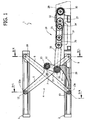
- figure 1 is a side elevational view of a preferred embodiment of the lifting device according to the invention, shown in an opened condition (platform in the raised position),
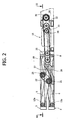
- figure 2 shows a side elevational of view of the device of figure 1 in a closed condition (platform in the lowered position),
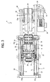
- figure 3 is a plan view, in a cross section taken along line III-III of figure 2, of the device of figures 1, 2,
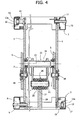
- figure 4 is a front end view and in cross-section of the device of figures 1-3, shown in an opened condition (platform in the raised position) along lines IV L and IV R of figure 1 (with reference to the left-hand part and the right-hand part of figure 4),
- figure 5 is a side view at an enlarged scale of the actuating device forming part of the device according to the invention,
- figure 6 (A-B) shows an array of pantograph-type lifting devices, synchronised with each other, respectively in a side view and in a plan view, and
- figure 7 (A-B) shows a detail of a variant of the actuating device comprising a connecting-rod-and-crank linkage, in a side view and in a plan view.
- In the drawings,
reference numeral 1 generally designates a lifting device of the type comprising a scissors-like linkage.Device 1 comprises alower structure 2 and anupper structure 3 in form of a table or platform movable with respect to thelower structure 2 between a raised position, shown in figure 1, and a lowered position, shown in figure 2. - Table 3 is connected to the
base structure 2 by means of a scissors-like linkage 4 which comprises two pairs of arms articulated to each other according to an X-shape and arranged in two vertical, parallel and spaced apart planes. Each pair of articulated arms comprises anarm 5 and anarm 6 articulated to each other around ahorizontal axis 7. Thearms 5 of the two pairs of articulated arms are arranged inside the twoarms 6, as shown in figure 4. - Each of the two
inner arms 5 has one of its ends articulated to thebase structure 2 around anaxis 8 which is horizontal and parallel toaxis 7, by means of anarticulation pin 9, visible in the left lower part of figure 4. Each of theouter arms 6, on its turn, has one end articulated to the structure of theplatform 3 around anaxis 10 parallel toaxes articulation pin 11 carried by the structure of table 3. Finally, the end of eachinner arm 5 opposite toarticulation 8 and the end of eachouter arm 6 opposite toarticulation 10support rollers 12 and 13 (figure 4) freely rotatable onpins 14, 15 (havingaxes arm 5 and thearm 6 and are guided on cooperatingtracks base structure 2. Due to this arrangement, the ends ofarms arms base structure 2 are movable relative to each other along two parallel horizontal planes, so as to ensure that the horizontal arrangement of table 3 is maintained during the entire raising or lowering movement of the table. - In figure 4, there are also
visible articulation pins 18 by whicharms axis 7. All the above mentioned articulations make preferably use of roller or ball bearings. - The movement of
linkage 4 between the lowered condition and the raised condition is controlled by an actuator unit generally designated byreference numeral 19. - As already specified in the foregoing, the actuator unit may be of any known type, but in the case of the preferred embodiment shown herein it comprises a hoist device with a belt engaged on pulleys.
- The specific arrangement and the operation of the embodiment of the
actuator 19 which is shown in the drawings will be described in detail in the following. For the time being, it will be sufficient to consider that theactuator unit 19 has one end pivotally mounted around anaxis 20 parallel toaxes base structure 2 and the opposite end pivotally connected around anaxis 21 to a connectingelement 22 which connects theactuator unit 19 to thelinkage 4. The connectingelement 22 has one end articulated around anaxis 23 parallel toaxes inner arms 5 of the two pairs of articulated arms of thelinkage 4. In figure 4 there is visible thearticulation pin 24 which is supported by the structure of the connectingelement 22 and is rotatably mounted at its ends within the twoinner arms 5. At the opposite end, the connectingelement 22 has a fork shape, with a pair of brackets to which there is fixed a pin 25 on which a cam-followingroller 26 is freely rotatably mounted. In the preferred embodiment shown herein, the axis of the cam-following roller is coincident with thearticulation axis 21 of theactuator unit 19 on theconnecting element 22. - The cam-following
roller 26 cooperates with acam surface 27 of acam element 28 fixed to thebase structure 2. The arrangement is such that thecam surface 27 causes a raising movement of the cam-followingroller 26 when the distance between thisroller 26 and thefixed axis 20 on which theactuator unit 19 is articulated is decreased, by activating theactuator unit 19. - As is shown, in any operating condition of the device, the
axis 21 of articulation of theactuator unit 19 to the connectingelement 22 is located below theaxis 23 of articulation of the connectingelement 22 to theinner arms 5. - Therefore, when the
actuator unit 19 is shortened to cause a raising movement of the device, the cam-followingroller 26 is compelled to raise along thecam surface 27 and the connectingelement 22 acts as a pushing strut, undergoing substantially to compression between theroller 26 and thearticulation 23 to the articulatedarm 5, so as to transform the pulling force applied by theactuator unit 19 into a force causing lifting of the device. Conversely, when theactuator unit 19 is elongated, the cam-followingroller 26 goes down along thecam surface 27 and the device is lowered in a controlled way, the weight of the upper table 3 and the load which may be present thereon being transformed into a compression force acting on the connectingelement 22, which again acts as a strut. - Also in the case of the preferred embodiment, the geometry of the
cam surface 27 is predetermined so that the force which theactuator unit 19 must exert is substantially constant along the entire movement of the lifting device between its lowered position and its raised position. - With reference to the preferred embodiment of the
actuator unit 19, which is visible particularly in figures 3 and 5, theaxis 20 of articulation of the actuator unit to thebase structure 2 is defined by a shaft 29 (figure 3) which is rotatably supported by thebase structure 2. Theshaft 29 is rotated by anelectric motor 30, by means of atransmission unit 31. In the specific case which is illustrated, the actuator unit is composed of two belt-type hoist devices which are identical and arranged side by side. Obviously the number of actuating systems which can be used may be any, as a function of the value of the masses to be moved. - In the illustrated example, on the
shaft 29 there are fixedly mounted twodrums 30 on each of which there is fixed one end of abelt 31. Eachbelt 31 is wound in more turns around therespective drum 30, which is arranged to receive the entire length of thebelt 31 which is necessary for the entire lifting movement. - On the
shaft 29 there is pivotally mounted a support structure 32 (figure 5) which supports a pair of freelyrotatable pulleys 33 and ashaft 34 to which the two opposite ends of the twobelts 31 are fixed. The actuator unit further comprises asecond structure 35 independent fromstructure 32, which is pivotally mounted aroundaxis 21 on the pin 25 carried by the connectingelement 22. Thestructure 35 freely rotatably supports pairs ofpulleys structures base structure 2 and the connectingelement 22 are separated from each other but connected to each other and kept aligned with each other by thebelts 31 which are wound in many turns around thepulleys flat belts 31, coming out tangentially fromdrums 30, are each wound by 180 degrees onpulley 36 which is freely rotatably mounted by rolling bearings onstructure 35 aroundaxis 36a. Eachbelt 31 is wound by 180 degrees on apulley 33 which also is freely rotatably mounted by means of rolling bearings on astructure 32, around anaxis 33a. Eachbelt 31 is then wound by 180 degrees on therespective pulley 36, which also is freely rotatably mounted by means of rolling bearings onstructure 35, around anaxis 37a. Finally, eachbelt 31 extends towardsshaft 34 which acts as anchoring member for the belt end and as a belt take-up member, on which the belt is fixed by means of a pressure pad (not shown). The anchoringmember 34 is a shaft to which one end of eachbelt 31 is anchored, this shaft being rotatable in order to put each belt under tension by winding the belt thereon. The rotation ofshaft 34 can be driven by a torque wrench (not shown). - Starting from the lowered condition of table 3, a clockwise rotation (with reference to figure 5) of
drums 30 causes winding thereon of the twobelts 31, and as a result, a relative movement of the twoend axes actuator unit 19 towards each other. During this stage, the tension imparted to the belts by winding thereof ondrums 30 keeps the twostructures actuator unit 19 causes the raising movement of the cam-followingroller 26 on thecam surface 27 and the resulting movement oflinkage 4 towards the raised condition, due to the action of the connectingelement 22 acting as a pushing strut. The use of many pulleys on which the belts are wound is equivalent to a conventional pulley lifting system which enables a reduction of the torque which must be imparted by the motor in order to cause lifting of a load. At the same time, as already illustrated, thecam surface 27 is preferably shaped so that the table and the mass thereon can be lifted through the application of a substantially constant torque by the motor. - In the lowering stage, it is the weight of the table 3 and the mass carried thereon which is discharged through the connecting
element 22 on the cam-followingroller 26, thus tending to cause an elongation of theactuator unit 19 which keeps the belts constantly in tension and maintain the twostructures actuator unit 19 aligned with each other. - With reference to figure 6, the device according to the invention can be connected and synchronised with a plurality of similar devices through mechanical connections in series, as shown in figure 6. In the illustrated example, the synchronisation is achieved by connecting tie-
rods 100 interposed between adjacent devices, so that only thedevice 1 at the beginning of each row of devices is provided with anactuator 19. Also the actuator units can have theirshafts 29 mutually connected byshafts 200, so that only a single motor unit is needed on each side of the array ofdevices 1. - The various devices connected in the above described way may have, in groups, the upper table in common, in order to move large masses.
- Figure 7 shows a variant in which the actuator device is not in the form of a belt-type hoist as shown in figure 5, but rather comprises a linkage including a connecting
rod 38 whosefoot 39 is connected to the foot of the connectingelement 22 and is therefore free to move along the profile ofcam 28, whereas thehead 40 of the connectingrod 38 is hinged, with the aid of a pair of rolling bearings, on an off-set pin of atoothed wheel 41 driven by the motor shaft. This solution, which is particularly indicated in the case of reduced displacements, and also for movements of sinusoidal type, has the advantage of having a very simple construction and therefore is particularly advantageous in setting up the device and also in its maintenance. - Furthermore, in the case of the solution of figure 7, the presence of two dead centres of the crank enables the two stop positions to be selected at said dead centres, so that the linkage can be actuated by the motor directly, with no need of an inverter, which is instead preferably used in the case of the previously described linkage. The connecting-rod-and-crank mechanism, along with the cam and the connecting
element 22, provides for the possibility of driving many different types of movements, such as movements at constant speed, or with a triangular profile of the speed variation, or with a trapezoidal profile of the speed, etc. - As it is clearly apparent from the foregoing, the preferred embodiment of the invention has the advantage that the cam is shaped so as to insure that the effort required for the motor remains substantially constant during the entire movement of the linkage. This result enables the use of a lifting motor having the same size which would be used in case of a conventional lifting device with simple vertical movement, where no variation of the torque of the motor is required during the entire lifting movement.
- Therefore, the device of the invention enables to drive the movement of the pantograph linkage in the same manner as is done in any lifting device with a simple vertical movement with a rack-and-pinion transmission or similar, thus ensuring the possibility of very high accelerations and/or speeds and the possibility to vary at will the acceleration and/or speed without implying the use of a lifting motor of larger size.
- It is further to be noted that the above described lifting device can be easily adapted also to linkages which, in their closed position, are very low and flat and characterised by reduced transverse dimensions. It also provides for the possibility of a constant movement at each step of the raising or lowering stage and can be used to lift masses of any amount, with no limitation.
- Naturally, while the principle of the invention remains the same, the details of construction and the embodiments may widely vary with respect to what has been described and illustrated purely by way of example, without departing from the scope of the present invention.
- The example illustrated with reference to the drawings annexed hereto has an
actuator unit 19 which operates with a pulling action in order to cause lifting of the device. This way of operation comes from that thecam surface 27 is facing towards the opposite side with respect to the articulatedend 20 of theactuator unit 19. Obviously, if the articulatedend 20 of the actuator unit is located on the left ofcam 28, with reference to figure 1, the actuator unit should work with a pushing action in order to cause lifting of the device, the lifting movement corresponding to an elongation of the actuator unit.
Claims (14)
- Lifting device, comprising:- a lower structure (2),- an upper structure (3) movable with respect to the lower structure (2) between a lowered position and a raised position,- a linkage (4) connecting the upper structure (3) to the lower structure (2), and including at least one articulated arm (5),- an actuator (19) operatively interposed between the lower structure (2) and the linkage (4), to drive the movement of the upper structure (3) between its lowered position and its raised position,- a connecting element (22) between the actuator (19) and the linkage (4), said connecting element (22) being articulated to said arm (5) of the linkage (4) and being provided with a cam-following element (26) cooperating with a fixed cam (28),characterised in that the actuator (19) is pivotally connected to said connecting element (22) around an axis (21) which is always located below the articulation axis (23) between the connecting element (22) and said articulated arm (5),
in such a way that, when the actuator (19) is activated to cause a lifting movement of the device, said connecting element (22) acts as a pushing strut subjected substantially to compression between the cam (28) and said articulated arm (5). - Device according to claim 1, characterised in that said actuator (19) is arranged to operate with a pushing action during the lifting movement of the device, by causing a raising movement of the cam-following element (26) along the cam (28).
- Device according to claim 1, characterised in that said actuator (19) is arranged to operate with a pulling action during lifting of the device, by causing a raising movement of the cam-following element (26) along the cam (28).
- Device according to claim 3, characterised in that said linkage is a scissors-like pantograph, comprising at least two arms (5, 6) articulated to each other according to a X-shape with two upper ends (10, 12) and two lower ends (8, 13) respectively connected to the upper structure (3) and the lower structure (2), said upper ends (10, 12) and said lower ends (8, 13) being guided on said upper structure (3) and on said lower structure (2) so that they are movable relative to each other along two parallel horizontal directions, the lower end (8) of one of said arms (5) being pivotally connected to the lower structure (2) around a fixed axis (8).
- Device according to claim 4, characterised in that said pushing strut (22) has a head articulated to one arm (5) of the pantograph and a foot pivotally connected to said actuator (19).
- Device according to claim 5, characterised in that said cam-following element is constituted by a roller (26) freely rotatably mounted on said pushing strut (22).
- Device according to claim 6, characterised in that said actuator (19) is pivotally connected to said pushing strut (22) around an axis (21) coincident with, or adjacent to, the axis of said cam-following roller (26).
- Device according to claim 7, characterised in that the scissors-like pantograph comprises two pairs of arms (5, 6) articulated to each other according to a X-shape and in that said pushing strut (22) is articulated to the inner arms (5) by means of a central articulation pin (24).
- Device according to claim 1, characterised in that said cam (28) has a cam surface (27) configured with a predetermined profile so as to keep the force which must be applied by the actuator (19) substantially constant during the entire movement of the lifting device.
- Device according to claim 9, characterised in that said pushing strut (22) has a structure with a fork-shaped end including two brackets connected to each other by a pin (25) on which said cam-following roller (27) is freely rotatably mounted.
- Device according to claim 1, characterised in that the actuator (19) is selected among an actuator unit including an electric motor connected to a screw-and-nut system, preferably with ball recirculation, a unit comprising an electric motor and a rack driven by the electric motor, a hydraulic cylinder, a unit including a motor and reducing unit and a connecting-rod-and-crank mechanism, or a hoist device using a belt, chord or chain.
- Device according to claim 1, characterised in that the actuator comprises a hoist device using a belt, chord or chain and including a number of pulleys on which said belt, chord or chain is engaged.
- Device according to claim 12, characterised in that said hoist device comprises a first structure (32) pivotally mounted around a fixed axis (20) on the lower structure (2), a second structure (35) pivotally mounted on said pushing strut (22), a number of pulleys (33, 34, 36, 37) freely rotatably mounted on said first structure (32) and said second structure (35) and at least one belt, chord or chain (31) having one end connected to a winding drum (30) carried by said first structure (32) and engaged around at least one freely rotatable pulley (36, 37) carried by said second structure (35) and at least one freely rotatable pulley (33) carried by said first structure (32) and having the opposite end anchored to a tensioning element (34) carried by said first structure (32), said actuator further comprising motor means for driving the rotation of said winding drum (30).
- Device according to claim 13, characterised in that it comprises a plurality of hoist devices arranged side by side and operating in synchronism.
Applications Claiming Priority (1)
| Application Number | Priority Date | Filing Date | Title |
|---|---|---|---|
| IT000149A ITFI20040149A1 (en) | 2004-06-29 | 2004-06-29 | LOAD LIFTING DEVICE |
Publications (2)
| Publication Number | Publication Date |
|---|---|
| EP1612183A1 EP1612183A1 (en) | 2006-01-04 |
| EP1612183B1 true EP1612183B1 (en) | 2007-01-10 |
Family
ID=34956549
Family Applications (1)
| Application Number | Title | Priority Date | Filing Date |
|---|---|---|---|
| EP05013103A Expired - Lifetime EP1612183B1 (en) | 2004-06-29 | 2005-06-17 | Load lifting device |
Country Status (12)
| Country | Link |
|---|---|
| US (1) | US7413056B2 (en) |
| EP (1) | EP1612183B1 (en) |
| JP (1) | JP4903400B2 (en) |
| KR (1) | KR101123480B1 (en) |
| CN (1) | CN1715174B (en) |
| AR (1) | AR049837A1 (en) |
| BR (1) | BRPI0502595A (en) |
| CA (1) | CA2510384C (en) |
| DE (1) | DE602005000433T2 (en) |
| ES (1) | ES2278359T3 (en) |
| IT (1) | ITFI20040149A1 (en) |
| MX (1) | MXPA05007055A (en) |
Cited By (1)
| Publication number | Priority date | Publication date | Assignee | Title |
|---|---|---|---|---|
| AU2010305280B2 (en) * | 2009-10-09 | 2015-10-08 | Maclean Engineering & Marketing Co. Limited | High performance equipment elevating device |
Families Citing this family (58)
| Publication number | Priority date | Publication date | Assignee | Title |
|---|---|---|---|---|
| DE102005030746A1 (en) * | 2005-06-29 | 2007-01-18 | Zf Friedrichshafen Ag | Suspension device with scissors pantograph |
| US7896134B2 (en) * | 2006-10-30 | 2011-03-01 | Lift-U, Division Of Hogan Mfg., Inc. | Low-rise vertical platform lift assembly with low-profile lifting mechanism |
| US8162159B2 (en) * | 2007-04-04 | 2012-04-24 | Carter Mark C | Modular garage storage |
| US20130277632A1 (en) * | 2008-09-03 | 2013-10-24 | Cemb S.P.A. | Lifting device, particularly for lifting wheels and the like, for wheel balancing and tire moving machines |
| US8714524B2 (en) * | 2009-12-16 | 2014-05-06 | Herkules Equipment Corporation | Belt-driven transportation system |
| US8662477B2 (en) * | 2009-12-16 | 2014-03-04 | Herkules Equipment Corporation | Belt-driven transportation system |
| US8602392B2 (en) * | 2009-12-24 | 2013-12-10 | Hossein Arghami Nia | Jack assembly for raising and lowering vehicles |
| IT1397438B1 (en) | 2009-12-30 | 2013-01-10 | Comau Spa | INSTALLATION FOR THE ASSEMBLY OF MECHANICAL PARTS ON BODIES OF MOTOR VEHICLES |
| US8733508B2 (en) | 2010-04-02 | 2014-05-27 | Herkules Equipment Corporation | Scissor lift assembly |
| RU2535772C2 (en) * | 2010-07-05 | 2014-12-20 | Коне Корпорейшн | Compensator and elevator |
| US20130094933A1 (en) * | 2011-10-12 | 2013-04-18 | Zhanhe XU | Stacking and unstacking machine, particularly for instrument transformer boxes |
| DE102011118672A1 (en) * | 2011-11-16 | 2013-05-16 | Christoph Mohr | Scissor |
| DE102012006028A1 (en) * | 2012-03-27 | 2013-10-02 | Rofa Industrial Automation Ag | Scissor |
| DK2676918T3 (en) * | 2012-06-20 | 2015-07-13 | develtex ApS | Scissor lift and use of the scissor lift |
| DE202013100340U1 (en) * | 2012-07-13 | 2013-02-08 | Rofa Industrial Automation Ag | Hubtischsteuerung |
| US9296596B2 (en) | 2012-10-15 | 2016-03-29 | Cameron Lanning Cormack | Hybrid wedge jack/scissor lift lifting apparatus and method of operation thereof |
| JP6318343B2 (en) * | 2012-11-13 | 2018-05-09 | 株式会社アグリライト研究所 | Plant cultivation system |
| CN103183294B (en) * | 2012-11-14 | 2015-04-22 | 湖北华昌达智能装备股份有限公司 | Belt tension structure and scissors lifting equipment applying same |
| CA2806456C (en) * | 2013-01-24 | 2014-04-29 | Norwood Industries Inc. | Log rest with rack and pinion system |
| US9254409B2 (en) | 2013-03-14 | 2016-02-09 | Icon Health & Fitness, Inc. | Strength training apparatus with flywheel and related methods |
| US9422142B2 (en) | 2013-08-01 | 2016-08-23 | Herkules Equipment Corporation | Scissor-type lift assembly |
| JP2015037153A (en) * | 2013-08-15 | 2015-02-23 | 富士通株式会社 | Case for electronic device and work table for case |
| CN105848733B (en) | 2013-12-26 | 2018-02-13 | 爱康保健健身有限公司 | Magnetic resistance mechanism in hawser apparatus |
| DK3145852T3 (en) * | 2014-05-22 | 2022-08-22 | Marta Fiorese | VEHICLE LIFT |
| CN103999761A (en) * | 2014-06-04 | 2014-08-27 | 魏延恕 | Hydraulic-driven foldable lifting frame type soilless cultivation system |
| US10426989B2 (en) | 2014-06-09 | 2019-10-01 | Icon Health & Fitness, Inc. | Cable system incorporated into a treadmill |
| US9387869B1 (en) | 2015-04-16 | 2016-07-12 | Aviad Berger | Luggage with mechanically integrated trolley |
| CN104876153B (en) * | 2015-05-29 | 2017-05-03 | 雅迪科技集团有限公司 | Lifting platform |
| CN105035694A (en) * | 2015-06-29 | 2015-11-11 | 广州大学 | Simple offside-preventing four-rod loading and unloading device for AGV (Automatic Guided Vehicle) |
| US9963307B2 (en) | 2015-07-13 | 2018-05-08 | Phillip STOLOFF | Container lifting and positioning support |
| TWI644702B (en) | 2015-08-26 | 2018-12-21 | 美商愛康運動與健康公司 | Strength exercise mechanisms |
| US10940360B2 (en) | 2015-08-26 | 2021-03-09 | Icon Health & Fitness, Inc. | Strength exercise mechanisms |
| EP3138807A1 (en) * | 2015-09-04 | 2017-03-08 | Siemens Aktiengesellschaft | Lifting device |
| WO2017059867A1 (en) * | 2015-10-08 | 2017-04-13 | Motion By Balle A/S | Scissor lift |
| CN105386634B (en) * | 2015-11-18 | 2018-06-01 | 朝阳电力勘测设计院有限公司 | A kind of high-tension line rapid rush-repair tower |
| US10441840B2 (en) | 2016-03-18 | 2019-10-15 | Icon Health & Fitness, Inc. | Collapsible strength exercise machine |
| US10293211B2 (en) | 2016-03-18 | 2019-05-21 | Icon Health & Fitness, Inc. | Coordinated weight selection |
| US10252109B2 (en) | 2016-05-13 | 2019-04-09 | Icon Health & Fitness, Inc. | Weight platform treadmill |
| US10661114B2 (en) | 2016-11-01 | 2020-05-26 | Icon Health & Fitness, Inc. | Body weight lift mechanism on treadmill |
| US10053343B1 (en) * | 2017-02-07 | 2018-08-21 | Rodney Cameron | Truck bed scissor lift |
| CN107963566A (en) * | 2018-01-05 | 2018-04-27 | 青岛诺诚化学品安全科技有限公司 | A kind of pulley cylinder group lifting device |
| WO2019153086A1 (en) * | 2018-02-07 | 2019-08-15 | Terracube International Inc. | Lift table and method of use |
| CN109160418B (en) * | 2018-10-26 | 2023-06-13 | 舟山市沥港船舶修造有限公司 | Multifunctional crane on ship |
| US11382422B1 (en) * | 2019-02-25 | 2022-07-12 | Frank Gatski | Overhead storage system and apparatus configured to raise and lower |
| TWI702072B (en) * | 2019-11-29 | 2020-08-21 | 昌祐科技國際股份有限公司 | Frame lifting mechanism for fitness equipment |
| KR102234491B1 (en) * | 2019-12-16 | 2021-03-31 | 주식회사 모션디바이스 | Apparatus for lifting of loading article |
| CN111115499B (en) * | 2019-12-30 | 2025-06-27 | 苏州市升乐迪机械科技有限公司 | Electric lifting cushion |
| DE102020206304A1 (en) * | 2020-05-19 | 2021-11-25 | Continental Teves Ag & Co. Ohg | Driverless transport vehicle with a payload lifting device and safety device |
| CN111847338B (en) * | 2020-08-01 | 2024-07-12 | 王昌佑 | Multi-tonnage large-amplitude lifting device with lever push-pull structure |
| CN112173385B (en) * | 2020-09-24 | 2022-06-24 | 苏州格力美特实验室科技发展有限公司 | Laboratory is with chemistry experiment instrument strorage device |
| CN112775909A (en) * | 2021-01-12 | 2021-05-11 | 广西汽车集团有限公司 | Mounting device of engine assembly |
| CN112829853B (en) * | 2021-02-07 | 2024-03-12 | 四川国软科技集团有限公司 | Pusher and AGV vehicle |
| JP7715335B2 (en) * | 2021-03-26 | 2025-07-30 | 公立大学法人前橋工科大学 | Transport cart |
| JP7715334B2 (en) * | 2021-03-26 | 2025-07-30 | 公立大学法人前橋工科大学 | Transport cart |
| JP7580719B2 (en) * | 2021-03-26 | 2024-11-12 | 公立大学法人前橋工科大学 | Lifting device |
| CN114191593B (en) * | 2021-12-15 | 2023-05-30 | 北京云迹科技股份有限公司 | Split type disinfection robot |
| KR102612190B1 (en) * | 2022-11-28 | 2023-12-11 | 주식회사 나우로보틱스 | Loading unit for robot and logistic robot system compatible with jacking type and picking type |
| CN117699325B (en) * | 2024-01-04 | 2024-05-10 | 江苏泰柯伟尔自动化设备有限公司 | Light belt conveyor |
Family Cites Families (22)
| Publication number | Priority date | Publication date | Assignee | Title |
|---|---|---|---|---|
| US2533980A (en) * | 1946-01-04 | 1950-12-12 | Weaver Engineering Co | Lifting and lowering appliance |
| US2862689A (en) * | 1955-11-03 | 1958-12-02 | Southworth Machine Co | Paper lift |
| US2928558A (en) * | 1957-04-09 | 1960-03-15 | Globe Machine Mfg Co Inc | Machine for tilting and lifting a load |
| US3246876A (en) * | 1963-12-26 | 1966-04-19 | Jeddeloh Bros Sweed Mills Inc | Scissor-lift mechanism |
| US3785462A (en) * | 1972-06-23 | 1974-01-15 | Applied Radiation Corp | Scissor lift and drive mechanism therefor |
| BR8300034A (en) * | 1982-01-07 | 1983-09-13 | Du Pont | COMPOUND; SUITABLE COMPOSITION TO CONTROL UNWANTED VEGETATION GROWTH; PROCESS TO CONTROL UNWANTED VEGETATION GROWTH |
| DE8229071U1 (en) * | 1982-10-16 | 1983-06-23 | Flexlift Hubgeräte GmbH, 4800 Bielefeld | LIFTING DEVICE |
| JPS60171996A (en) * | 1984-02-13 | 1985-09-05 | 富士変速機株式会社 | Table lift gear |
| US5054578A (en) * | 1987-02-24 | 1991-10-08 | C. M. Smillie & Company | Power-operated lift and presenting mechanism |
| JPS6424094A (en) * | 1987-07-21 | 1989-01-26 | Nat Inst Res Inorganic Mat | Synthesizing apparatus for diamond |
| JPH01104597A (en) * | 1987-10-14 | 1989-04-21 | Cosmic Kogyo Kk | Lifter |
| JPH01301480A (en) * | 1988-05-27 | 1989-12-05 | Honda Motor Co Ltd | Heavy object transfer method and transfer device |
| JPH01303298A (en) * | 1988-05-30 | 1989-12-07 | Matehan Eng Kk | Table lifter |
| CN2104204U (en) * | 1991-07-04 | 1992-05-13 | 山西太原·索斯沃斯升降台有限公司 | Hydraulic lift platform for mine |
| US5395209A (en) * | 1992-04-17 | 1995-03-07 | Busse Bros. Inc. | Palletizer |
| EP0839757A1 (en) * | 1996-10-29 | 1998-05-06 | Hans Balle Christensen | Lifting mechanism |
| JPH10218582A (en) * | 1997-02-03 | 1998-08-18 | Shimadzu Corp | Lifter |
| JP3068591B1 (en) * | 1999-02-19 | 2000-07-24 | 新明和リビテック株式会社 | Lifting equipment |
| JP2001031379A (en) * | 1999-07-22 | 2001-02-06 | Takashi Ito | Lift for wheelchair |
| US6516478B2 (en) * | 2001-05-31 | 2003-02-11 | Health & Technology, Inc. | Adjustable height bed |
| JP3595780B2 (en) * | 2001-07-11 | 2004-12-02 | 日本機器鋼業株式会社 | Lifter |
| DE20209407U1 (en) * | 2002-06-17 | 2003-07-31 | REMECH Systemtechnik GmbH & Co. KG, 07334 Kamsdorf | Lifting device, preferably for skid conveyors |
-
2004
- 2004-06-29 IT IT000149A patent/ITFI20040149A1/en unknown
-
2005
- 2005-06-17 DE DE602005000433T patent/DE602005000433T2/en not_active Expired - Lifetime
- 2005-06-17 ES ES05013103T patent/ES2278359T3/en not_active Expired - Lifetime
- 2005-06-17 EP EP05013103A patent/EP1612183B1/en not_active Expired - Lifetime
- 2005-06-21 CA CA2510384A patent/CA2510384C/en not_active Expired - Fee Related
- 2005-06-27 KR KR1020050055492A patent/KR101123480B1/en not_active Expired - Fee Related
- 2005-06-28 JP JP2005188525A patent/JP4903400B2/en not_active Expired - Fee Related
- 2005-06-28 US US11/169,047 patent/US7413056B2/en not_active Expired - Fee Related
- 2005-06-28 MX MXPA05007055A patent/MXPA05007055A/en active IP Right Grant
- 2005-06-29 BR BR0502595-8A patent/BRPI0502595A/en active Search and Examination
- 2005-06-29 CN CN2005100810692A patent/CN1715174B/en not_active Expired - Fee Related
- 2005-06-29 AR ARP050102682A patent/AR049837A1/en not_active Application Discontinuation
Cited By (1)
| Publication number | Priority date | Publication date | Assignee | Title |
|---|---|---|---|---|
| AU2010305280B2 (en) * | 2009-10-09 | 2015-10-08 | Maclean Engineering & Marketing Co. Limited | High performance equipment elevating device |
Also Published As
| Publication number | Publication date |
|---|---|
| JP2006016211A (en) | 2006-01-19 |
| ES2278359T3 (en) | 2007-08-01 |
| JP4903400B2 (en) | 2012-03-28 |
| KR20060048537A (en) | 2006-05-18 |
| CN1715174A (en) | 2006-01-04 |
| DE602005000433T2 (en) | 2007-10-31 |
| BRPI0502595A (en) | 2006-02-07 |
| DE602005000433D1 (en) | 2007-02-22 |
| CA2510384A1 (en) | 2005-12-29 |
| US7413056B2 (en) | 2008-08-19 |
| US20060169543A1 (en) | 2006-08-03 |
| CA2510384C (en) | 2012-08-21 |
| ITFI20040149A1 (en) | 2004-09-29 |
| MXPA05007055A (en) | 2006-01-11 |
| CN1715174B (en) | 2010-06-16 |
| EP1612183A1 (en) | 2006-01-04 |
| KR101123480B1 (en) | 2012-03-26 |
| AR049837A1 (en) | 2006-09-06 |
Similar Documents
| Publication | Publication Date | Title |
|---|---|---|
| EP1612183B1 (en) | Load lifting device | |
| CN103979459B (en) | Lowering or hoisting gear | |
| US9340398B2 (en) | Scissor lift table | |
| CN1315717C (en) | Scissors type lifting equipment | |
| US4375248A (en) | Lifting apparatus | |
| CN111039196B (en) | Movable counterweight device with combined shear fork of movable arm tower crane and use method of movable counterweight device | |
| JP2002544095A (en) | Scissors type lift table | |
| US6779635B1 (en) | Mechanism for providing motion and force while maintaining parallelism between a base structure and a movable structure | |
| US3836017A (en) | Apparatus for transferring articles between a conveyor and a stack | |
| CN113582075A (en) | Lifting feeding device | |
| SU1401006A1 (en) | Load-lifting table | |
| JP3018710U (en) | Trolley with lift | |
| KR200334043Y1 (en) | Lifting beam driving unit | |
| KR20080006850A (en) | Belt Driven Mechanical Lifts | |
| RU2335454C1 (en) | Load lifting table | |
| US4032019A (en) | Billet conveyor and turner | |
| RU2280007C1 (en) | Load-lifting table | |
| JPH01104597A (en) | Lifter | |
| CN201901450U (en) | Stacking system | |
| RU2342312C1 (en) | Load lifting table | |
| CN110921569B (en) | Automatic unloading machine for strip-shaped material and working method | |
| RU2361807C1 (en) | Hoisting table | |
| RU1768475C (en) | Step-by-step conveyor | |
| SU1664716A1 (en) | Gripping device for palletized cargo | |
| RU2361808C1 (en) | Hoisting table |
Legal Events
| Date | Code | Title | Description |
|---|---|---|---|
| PUAI | Public reference made under article 153(3) epc to a published international application that has entered the european phase |
Free format text: ORIGINAL CODE: 0009012 |
|
| AK | Designated contracting states |
Kind code of ref document: A1 Designated state(s): AT BE BG CH CY CZ DE DK EE ES FI FR GB GR HU IE IS IT LI LT LU MC NL PL PT RO SE SI SK TR |
|
| AX | Request for extension of the european patent |
Extension state: AL BA HR LV MK YU |
|
| 17P | Request for examination filed |
Effective date: 20060505 |
|
| GRAP | Despatch of communication of intention to grant a patent |
Free format text: ORIGINAL CODE: EPIDOSNIGR1 |
|
| AKX | Designation fees paid |
Designated state(s): AT BE BG CH CY CZ DE DK EE ES FI FR GB GR HU IE IS IT LI LT LU MC NL PL PT RO SE SI SK TR |
|
| GRAS | Grant fee paid |
Free format text: ORIGINAL CODE: EPIDOSNIGR3 |
|
| GRAA | (expected) grant |
Free format text: ORIGINAL CODE: 0009210 |
|
| AK | Designated contracting states |
Kind code of ref document: B1 Designated state(s): AT BE BG CH CY CZ DE DK EE ES FI FR GB GR HU IE IS IT LI LT LU MC NL PL PT RO SE SI SK TR |
|
| PG25 | Lapsed in a contracting state [announced via postgrant information from national office to epo] |
Ref country code: CH Free format text: LAPSE BECAUSE OF FAILURE TO SUBMIT A TRANSLATION OF THE DESCRIPTION OR TO PAY THE FEE WITHIN THE PRESCRIBED TIME-LIMIT Effective date: 20070110 Ref country code: FI Free format text: LAPSE BECAUSE OF FAILURE TO SUBMIT A TRANSLATION OF THE DESCRIPTION OR TO PAY THE FEE WITHIN THE PRESCRIBED TIME-LIMIT Effective date: 20070110 Ref country code: PL Free format text: LAPSE BECAUSE OF FAILURE TO SUBMIT A TRANSLATION OF THE DESCRIPTION OR TO PAY THE FEE WITHIN THE PRESCRIBED TIME-LIMIT Effective date: 20070110 Ref country code: SI Free format text: LAPSE BECAUSE OF FAILURE TO SUBMIT A TRANSLATION OF THE DESCRIPTION OR TO PAY THE FEE WITHIN THE PRESCRIBED TIME-LIMIT Effective date: 20070110 Ref country code: NL Free format text: LAPSE BECAUSE OF FAILURE TO SUBMIT A TRANSLATION OF THE DESCRIPTION OR TO PAY THE FEE WITHIN THE PRESCRIBED TIME-LIMIT Effective date: 20070110 Ref country code: LI Free format text: LAPSE BECAUSE OF FAILURE TO SUBMIT A TRANSLATION OF THE DESCRIPTION OR TO PAY THE FEE WITHIN THE PRESCRIBED TIME-LIMIT Effective date: 20070110 Ref country code: DK Free format text: LAPSE BECAUSE OF FAILURE TO SUBMIT A TRANSLATION OF THE DESCRIPTION OR TO PAY THE FEE WITHIN THE PRESCRIBED TIME-LIMIT Effective date: 20070110 |
|
| REG | Reference to a national code |
Ref country code: GB Ref legal event code: FG4D |
|
| REG | Reference to a national code |
Ref country code: IE Ref legal event code: FG4D |
|
| REF | Corresponds to: |
Ref document number: 602005000433 Country of ref document: DE Date of ref document: 20070222 Kind code of ref document: P |
|
| PG25 | Lapsed in a contracting state [announced via postgrant information from national office to epo] |
Ref country code: BG Free format text: LAPSE BECAUSE OF FAILURE TO SUBMIT A TRANSLATION OF THE DESCRIPTION OR TO PAY THE FEE WITHIN THE PRESCRIBED TIME-LIMIT Effective date: 20070410 Ref country code: SE Free format text: LAPSE BECAUSE OF FAILURE TO SUBMIT A TRANSLATION OF THE DESCRIPTION OR TO PAY THE FEE WITHIN THE PRESCRIBED TIME-LIMIT Effective date: 20070410 |
|
| PG25 | Lapsed in a contracting state [announced via postgrant information from national office to epo] |
Ref country code: IS Free format text: LAPSE BECAUSE OF FAILURE TO SUBMIT A TRANSLATION OF THE DESCRIPTION OR TO PAY THE FEE WITHIN THE PRESCRIBED TIME-LIMIT Effective date: 20070510 |
|
| ET | Fr: translation filed | ||
| PG25 | Lapsed in a contracting state [announced via postgrant information from national office to epo] |
Ref country code: PT Free format text: LAPSE BECAUSE OF FAILURE TO SUBMIT A TRANSLATION OF THE DESCRIPTION OR TO PAY THE FEE WITHIN THE PRESCRIBED TIME-LIMIT Effective date: 20070611 |
|
| NLV1 | Nl: lapsed or annulled due to failure to fulfill the requirements of art. 29p and 29m of the patents act | ||
| REG | Reference to a national code |
Ref country code: CH Ref legal event code: PL |
|
| REG | Reference to a national code |
Ref country code: ES Ref legal event code: FG2A Ref document number: 2278359 Country of ref document: ES Kind code of ref document: T3 |
|
| PLBE | No opposition filed within time limit |
Free format text: ORIGINAL CODE: 0009261 |
|
| STAA | Information on the status of an ep patent application or granted ep patent |
Free format text: STATUS: NO OPPOSITION FILED WITHIN TIME LIMIT |
|
| PG25 | Lapsed in a contracting state [announced via postgrant information from national office to epo] |
Ref country code: SK Free format text: LAPSE BECAUSE OF FAILURE TO SUBMIT A TRANSLATION OF THE DESCRIPTION OR TO PAY THE FEE WITHIN THE PRESCRIBED TIME-LIMIT Effective date: 20070110 |
|
| 26N | No opposition filed |
Effective date: 20071011 |
|
| PG25 | Lapsed in a contracting state [announced via postgrant information from national office to epo] |
Ref country code: RO Free format text: LAPSE BECAUSE OF FAILURE TO SUBMIT A TRANSLATION OF THE DESCRIPTION OR TO PAY THE FEE WITHIN THE PRESCRIBED TIME-LIMIT Effective date: 20070110 Ref country code: CZ Free format text: LAPSE BECAUSE OF FAILURE TO SUBMIT A TRANSLATION OF THE DESCRIPTION OR TO PAY THE FEE WITHIN THE PRESCRIBED TIME-LIMIT Effective date: 20070110 |
|
| PG25 | Lapsed in a contracting state [announced via postgrant information from national office to epo] |
Ref country code: MC Free format text: LAPSE BECAUSE OF NON-PAYMENT OF DUE FEES Effective date: 20070630 |
|
| PG25 | Lapsed in a contracting state [announced via postgrant information from national office to epo] |
Ref country code: LT Free format text: LAPSE BECAUSE OF FAILURE TO SUBMIT A TRANSLATION OF THE DESCRIPTION OR TO PAY THE FEE WITHIN THE PRESCRIBED TIME-LIMIT Effective date: 20070110 |
|
| PG25 | Lapsed in a contracting state [announced via postgrant information from national office to epo] |
Ref country code: GR Free format text: LAPSE BECAUSE OF FAILURE TO SUBMIT A TRANSLATION OF THE DESCRIPTION OR TO PAY THE FEE WITHIN THE PRESCRIBED TIME-LIMIT Effective date: 20070411 |
|
| PG25 | Lapsed in a contracting state [announced via postgrant information from national office to epo] |
Ref country code: IE Free format text: LAPSE BECAUSE OF NON-PAYMENT OF DUE FEES Effective date: 20070618 |
|
| PG25 | Lapsed in a contracting state [announced via postgrant information from national office to epo] |
Ref country code: EE Free format text: LAPSE BECAUSE OF FAILURE TO SUBMIT A TRANSLATION OF THE DESCRIPTION OR TO PAY THE FEE WITHIN THE PRESCRIBED TIME-LIMIT Effective date: 20070110 |
|
| PG25 | Lapsed in a contracting state [announced via postgrant information from national office to epo] |
Ref country code: CY Free format text: LAPSE BECAUSE OF FAILURE TO SUBMIT A TRANSLATION OF THE DESCRIPTION OR TO PAY THE FEE WITHIN THE PRESCRIBED TIME-LIMIT Effective date: 20070110 |
|
| PG25 | Lapsed in a contracting state [announced via postgrant information from national office to epo] |
Ref country code: LU Free format text: LAPSE BECAUSE OF NON-PAYMENT OF DUE FEES Effective date: 20070617 |
|
| PG25 | Lapsed in a contracting state [announced via postgrant information from national office to epo] |
Ref country code: TR Free format text: LAPSE BECAUSE OF FAILURE TO SUBMIT A TRANSLATION OF THE DESCRIPTION OR TO PAY THE FEE WITHIN THE PRESCRIBED TIME-LIMIT Effective date: 20070110 Ref country code: HU Free format text: LAPSE BECAUSE OF FAILURE TO SUBMIT A TRANSLATION OF THE DESCRIPTION OR TO PAY THE FEE WITHIN THE PRESCRIBED TIME-LIMIT Effective date: 20070711 |
|
| PG25 | Lapsed in a contracting state [announced via postgrant information from national office to epo] |
Ref country code: IT Free format text: LAPSE BECAUSE OF NON-PAYMENT OF DUE FEES Effective date: 20090617 |
|
| PGRI | Patent reinstated in contracting state [announced from national office to epo] |
Ref country code: IT Effective date: 20110616 |
|
| REG | Reference to a national code |
Ref country code: FR Ref legal event code: PLFP Year of fee payment: 12 |
|
| REG | Reference to a national code |
Ref country code: FR Ref legal event code: PLFP Year of fee payment: 13 |
|
| PGFP | Annual fee paid to national office [announced via postgrant information from national office to epo] |
Ref country code: GB Payment date: 20170630 Year of fee payment: 13 Ref country code: FR Payment date: 20170629 Year of fee payment: 13 |
|
| PGFP | Annual fee paid to national office [announced via postgrant information from national office to epo] |
Ref country code: IT Payment date: 20170619 Year of fee payment: 13 Ref country code: AT Payment date: 20170627 Year of fee payment: 13 Ref country code: BE Payment date: 20170627 Year of fee payment: 13 |
|
| PGFP | Annual fee paid to national office [announced via postgrant information from national office to epo] |
Ref country code: DE Payment date: 20170831 Year of fee payment: 13 Ref country code: ES Payment date: 20170724 Year of fee payment: 13 |
|
| REG | Reference to a national code |
Ref country code: DE Ref legal event code: R119 Ref document number: 602005000433 Country of ref document: DE |
|
| REG | Reference to a national code |
Ref country code: AT Ref legal event code: MM01 Ref document number: 351147 Country of ref document: AT Kind code of ref document: T Effective date: 20180617 |
|
| GBPC | Gb: european patent ceased through non-payment of renewal fee |
Effective date: 20180617 |
|
| REG | Reference to a national code |
Ref country code: BE Ref legal event code: MM Effective date: 20180630 |
|
| PG25 | Lapsed in a contracting state [announced via postgrant information from national office to epo] |
Ref country code: GB Free format text: LAPSE BECAUSE OF NON-PAYMENT OF DUE FEES Effective date: 20180617 Ref country code: IT Free format text: LAPSE BECAUSE OF NON-PAYMENT OF DUE FEES Effective date: 20180617 Ref country code: AT Free format text: LAPSE BECAUSE OF NON-PAYMENT OF DUE FEES Effective date: 20180617 Ref country code: DE Free format text: LAPSE BECAUSE OF NON-PAYMENT OF DUE FEES Effective date: 20190101 Ref country code: FR Free format text: LAPSE BECAUSE OF NON-PAYMENT OF DUE FEES Effective date: 20180630 |
|
| PG25 | Lapsed in a contracting state [announced via postgrant information from national office to epo] |
Ref country code: BE Free format text: LAPSE BECAUSE OF NON-PAYMENT OF DUE FEES Effective date: 20180630 |
|
| REG | Reference to a national code |
Ref country code: ES Ref legal event code: FD2A Effective date: 20190916 |
|
| PG25 | Lapsed in a contracting state [announced via postgrant information from national office to epo] |
Ref country code: ES Free format text: LAPSE BECAUSE OF NON-PAYMENT OF DUE FEES Effective date: 20180618 |