EP1612107A1 - Bumper structure - Google Patents
Bumper structure Download PDFInfo
- Publication number
- EP1612107A1 EP1612107A1 EP05014187A EP05014187A EP1612107A1 EP 1612107 A1 EP1612107 A1 EP 1612107A1 EP 05014187 A EP05014187 A EP 05014187A EP 05014187 A EP05014187 A EP 05014187A EP 1612107 A1 EP1612107 A1 EP 1612107A1
- Authority
- EP
- European Patent Office
- Prior art keywords
- bumper
- garnish
- pipe member
- vehicle
- washer hose
- Prior art date
- Legal status (The legal status is an assumption and is not a legal conclusion. Google has not performed a legal analysis and makes no representation as to the accuracy of the status listed.)
- Granted
Links
Images



Classifications
-
- B—PERFORMING OPERATIONS; TRANSPORTING
- B60—VEHICLES IN GENERAL
- B60S—SERVICING, CLEANING, REPAIRING, SUPPORTING, LIFTING, OR MANOEUVRING OF VEHICLES, NOT OTHERWISE PROVIDED FOR
- B60S1/00—Cleaning of vehicles
- B60S1/02—Cleaning windscreens, windows or optical devices
- B60S1/46—Cleaning windscreens, windows or optical devices using liquid; Windscreen washers
- B60S1/48—Liquid supply therefor
- B60S1/52—Arrangement of nozzles; Liquid spreading means
- B60S1/522—Arrangement of nozzles; Liquid spreading means moving liquid spreading means, e.g. arranged in wiper arms
- B60S1/528—Arrangement of nozzles; Liquid spreading means moving liquid spreading means, e.g. arranged in wiper arms the spreading means being moved between a rest position and a working position
-
- B—PERFORMING OPERATIONS; TRANSPORTING
- B60—VEHICLES IN GENERAL
- B60R—VEHICLES, VEHICLE FITTINGS, OR VEHICLE PARTS, NOT OTHERWISE PROVIDED FOR
- B60R19/00—Wheel guards; Radiator guards, e.g. grilles; Obstruction removers; Fittings damping bouncing force in collisions
- B60R19/02—Bumpers, i.e. impact receiving or absorbing members for protecting vehicles or fending off blows from other vehicles or objects
- B60R19/48—Bumpers, i.e. impact receiving or absorbing members for protecting vehicles or fending off blows from other vehicles or objects combined with, or convertible into, other devices or objects, e.g. bumpers combined with road brushes, bumpers convertible into beds
-
- B—PERFORMING OPERATIONS; TRANSPORTING
- B62—LAND VEHICLES FOR TRAVELLING OTHERWISE THAN ON RAILS
- B62D—MOTOR VEHICLES; TRAILERS
- B62D25/00—Superstructure or monocoque structure sub-units; Parts or details thereof not otherwise provided for
- B62D25/08—Front or rear portions
- B62D25/082—Engine compartments
- B62D25/084—Radiator supports
-
- B—PERFORMING OPERATIONS; TRANSPORTING
- B60—VEHICLES IN GENERAL
- B60R—VEHICLES, VEHICLE FITTINGS, OR VEHICLE PARTS, NOT OTHERWISE PROVIDED FOR
- B60R19/00—Wheel guards; Radiator guards, e.g. grilles; Obstruction removers; Fittings damping bouncing force in collisions
- B60R19/02—Bumpers, i.e. impact receiving or absorbing members for protecting vehicles or fending off blows from other vehicles or objects
- B60R19/18—Bumpers, i.e. impact receiving or absorbing members for protecting vehicles or fending off blows from other vehicles or objects characterised by the cross-section; Means within the bumper to absorb impact
- B60R2019/1886—Bumper fascias and fastening means therefor
-
- B—PERFORMING OPERATIONS; TRANSPORTING
- B60—VEHICLES IN GENERAL
- B60R—VEHICLES, VEHICLE FITTINGS, OR VEHICLE PARTS, NOT OTHERWISE PROVIDED FOR
- B60R19/00—Wheel guards; Radiator guards, e.g. grilles; Obstruction removers; Fittings damping bouncing force in collisions
- B60R19/02—Bumpers, i.e. impact receiving or absorbing members for protecting vehicles or fending off blows from other vehicles or objects
- B60R19/48—Bumpers, i.e. impact receiving or absorbing members for protecting vehicles or fending off blows from other vehicles or objects combined with, or convertible into, other devices or objects, e.g. bumpers combined with road brushes, bumpers convertible into beds
- B60R2019/486—Bumpers, i.e. impact receiving or absorbing members for protecting vehicles or fending off blows from other vehicles or objects combined with, or convertible into, other devices or objects, e.g. bumpers combined with road brushes, bumpers convertible into beds with air passages, e.g. for cooling
Definitions
- the present invention relates to a bumper structure provided with a piping for washing liquid and the like.
- a washer nozzle that sprays a washing liquid towards a headlight is provided on a bumper, and to attain this, a pipe member that supplies washing liquid to this washing nozzle is arranged within the bumper.
- a pipe member that supplies washing liquid to this washing nozzle is arranged within the bumper.
- the pipe member is retained by using separate clips.
- the washing liquid supply path is integrally formed in the bumper (Japanese Unexamined Patent Application, First Publication No. H07-179157).
- clips become unnecessary, it is possible to reduce the number of parts, it is possible to reduce the mounting time, and at the same time, it is possible to improve the appearance after the pipe member is arranged.
- the washing liquid supply path is integrally formed on the upper surface of the bumper body, which mainly forms the design surface (design surface).
- the shape of the bumper body is complicated, shrinkage defects may occur during molding. This kind of defect is particularly conspicuous when it occurs in the bumper body, and thereby in terms of the quality of the external appearance, there is a new problem differing from that of the clips described above.
- an object of the present invention is to provide a bumper structure that enables reducing the number of parts, enables reducing the mounting time, enables improving the appearance after a pipe member is arranged, and thereby enables preventing degradation in the quality of the external appearance of the bumper body.
- a first aspect of the present invention provides a bumper structure including: a bumper body; a bumper garnish disposed in an opening defined in the bumper body; and a retaining device integrally formed in the bumper garnish and retaining a pipe member.
- the retaining device that retains the pipe member is integrally formed on the bumper garnish that is provided in an opening formed on the bumper body, the pipe member needs only to be retained by the retaining device, and it is not necessary to use separate clips. Therefore, it is possible to reduce the number of parts and to reduce the mounting time. At the same time, it is possible to improve the appearance after the pipe member is arranged.
- the retaining device that retains the pipe member is integrally formed in the bumper garnish, even if shrinkage defects occur in the bumper garnish, this will not affect the bumper body, which forms the main portion of the design surface. Therefore, it is possible to prevent degradation in the quality of the external appearance of the bumper body.
- the bumper garnish may be is disposed along a lengthwise direction of the bumper body, and the retaining device may retain the pipe member in an arrangement in which the pipe member is arranged along a lengthwise direction of the bumper garnish and along an edge portion of the bumper garnish that extends in the lengthwise direction of the bumper garnish.
- the pipe member is arranged along the lengthwise direction of the bumper garnish with respect to the retaining device that retains the pipe member so as to be oriented along the edge of the bumper garnish that extends in the lengthwise direction.
- the retaining orientation and the arrangement direction are identical, and as a result, it is possible to arrange the pipe member easily. Therefore, large bends and the like do not occur in the pipe member, and the flow of liquid therein is not hindered.
- the retaining device may include, in a lengthwise end region of the bumper garnish, a clamping device that conforms to a shape of the pipe member, and a slit portion that is located closer to an end of the bumper garnish than the clamping device, and the pipe member may be arranged by being retained by the clamping device and being inserted through the slit portion.
- the pipe member is inserted through the slit portions at the ends of the bumper garnish in the lengthwise direction, which are closer to the end portions than the clamping devices, so as to be guided to the outside.
- the pipe member is guided to the outside, and arrangement is carried out easily while avoiding the center portion in the lengthwise direction, whose layout design is difficult. Therefore, large bends and the like do not occur in the pipe member, and the flow of the liquid therein is not hindered.
- the pipe member is inserted through the slit portions after being retained in the bumper garnish by the clamping devices, and thus the pipe member can be guided through the slit portions to the outside without separating from the bumper garnish.
- the bumper garnish may be disposed below of a bumper beam that is connected to a body frame, and the pipe member may be arranged along a lower edge portion of the bumper garnish.
- the pipe member is provided along the lower edge portion of the bumper garnish that is provided below the bumper beam, and thus it is possible to arrange the pipe member while avoiding the bumper beam.
- the term longitudinal refers to the front-to-back direction of the vehicle body.
- FIG. 1 is a drawing viewing a bumper 11 and the vicinity thereof from the back side (rear side).
- a bumper beam 13 is provided along the widthwise direction of the vehicle on the front side of the frame-shaped radiator core support 12, and the bumper 11 is provided along the widthwise direction of the vehicle closer to the front than this bumper beam 13.
- the bumper 11 has a bumper body 20 that extends in the widthwise direction of the vehicle and mainly forms the design surface of the vehicle.
- Nozzle openings 21 are formed in the upper portion of both ends of the bumper body 20 in the widthwise direction of the vehicle.
- an air intake opening 22 (an opening) extending in the widthwise direction of the vehicle is formed in the lower portion of the bumper body 20 in the center in the widthwise direction of the vehicle.
- the bumper body 20 is integrally formed using a synthetic resin, and normally is used after the surface is coated.
- the nozzle opening 21 allows the washer nozzle 25 shown in FIG. 3 to project and retract.
- the washer nozzle 25 is for washing the headlight 24.
- the washer nozzle 25 includes a base portion 26 that is mounted on the back side of the bumper body 20 and a nozzle body 27 that projects outside of the bumper body 20 from the base portion 26 through the nozzle opening 21 and retracts therein.
- a cover 28 is provided on the upper end of the nozzle body 27, and the nozzle opening 21 is closed by this cover 28 when the nozzle body 27 retracts into the bumper body 20.
- the bumper 11 has a bumper garnish 31 that is provided over the entire air intake opening 22, which extends in the lengthwise direction of the bumper body 20.
- This bumper garnish 31 has a shape that extends in the widthwise direction of the vehicle, conforming to the shape of the air intake opening 22. That is, the bumper garnish 31 is provided along the lengthwise direction of the bumper body 20.
- the bumper garnish 31 includes a frame 32 that forms the outside edge thereof, a transverse plate 33 extending along the widthwise direction of the vehicle at the center of the frame 32 in the vertical direction, and vertical plates 34 extending along the vertical direction at a plurality of locations on the frame 32 in the widthwise direction of the vehicle.
- the center upper portions in the widthwise direction of the vehicle form the closed portions 35 and the remainder forms the openings 36, which are open.
- This bumper garnish 31 is mounted on a plurality of installation portions 38 provided on the upper edge of the frame 32 and on an installation portion (not illustrated) provided on the lower edge of the frame so as to be in contact with the back surface of the peripheral edge of the air intake opening 22 of the bumper body 20. Note that, as shown in FIG. 1, the bumper garnish 31 is disposed below the bumper body 13.
- Clamping devices (a retaining device) 42 that conform to the shape of the washer hose 41 are formed in plurality on the bumper garnish 31 at predetermined intervals in the widthwise direction of the vehicle.
- the clamping devices 42 are for retaining the washer hose (pipe member) 41 along the lower edge of the frame 32.
- the washer hose 41 communicates with the washer nozzle 25 described above and supplies washing liquid.
- the slit portions (a retaining device) 43 that retain the washer hose 41 are formed in the widthwise direction outside the clamping devices 42 at both ends in the widthwise direction of the vehicle. That is, the clamping devices 42, which conform to the shape of the washer hose 41, and slit portions 43, which are closer to the end portions than the clamping devices 42, are formed at the ends of the bumper garnish 31 in the lengthwise direction.
- each of the clamping devices 42 perpendicular to the widthwise direction of the vehicle opens upward so as to conform to the shape of the washer hose 41, and at the same time, the upper end forms a curved shape that is closer to the frame 32 than the bottom thereof, and this cross-section forms a shape that is continuous in the widthwise direction of the vehicle.
- the circular shaped washer hose 41 is pushed downward from the top into each of the clamping devices 42 to an orientation that extends in the widthwise direction of the vehicle, and thereby each of the clamping devices 42 retains the circumferential surface of the washer hose 41 against the frame 32. In this state, the clamping devices 42 retain the washer hose 41 oriented along the lower edge of the frame 32 of the bumper garnish 31 that extends in the lengthwise direction and in proximity to the lower edge thereof.
- the slit portions 43 are formed in outside regions, as viewed in the widthwise direction of the vehicle, of the frames 32 that respectively house clamping devices 42 located at both ends in the widthwise direction of the vehicle at intervals that are narrower than the intervals between adjacent clamping devices 42.
- the slit portions 43 have a shape that passes through the frame 32 in a substantially longitudinal direction of the vehicle and exit at the bottom.
- the outer edges of the slit portions 43 in the widthwise direction of the vehicle are offset more than the inner edges of the slit portions 43 in the widthwise direction of the vehicle on the rear side in the lengthwise direction of the vehicle.
- the washer hose 41 that is pressed into the slit portions 43 from below is retained in an orientation substantially along the lengthwise direction of the bumper garnish 31.
- the width of the bottom of the slit portions 43 is narrower than the width of the top so that the washer hose 41 can be retained at the top.
- the bumper garnish 31 is integrally formed using a synthetic resin, and is used without coating.
- the clamping devices 42 and the slit portions 43 that retain the washer hose 41 are both integrally formed on the bumper garnish 31.
- the entire washer hose 41 is aligned in the widthwise direction of the vehicle.
- the washer hose 41 is guided to the outside (front side) of the bumper garnish 31, and thereby the center portion of the washer hose 41 provided inside (rear side) the bumper garnish 31 is retained by being inserted into the plurality of clamps 42.
- the washer hose 41 which is retained by the clamps 42 so as to be oriented along the lower edge portion of the bumper garnish 31 that extends in the lengthwise direction, is arranged along and in proximity to the lower edge portion of the bumper garnish 31 that extends in the lengthwise direction.
- a portion of the washer hose 41 that exits through the slit portions 43 to the front of the bumper garnish 31 and extends to the outside in the widthwise direction of the vehicle passes between the bumper body 20 and the radiator core support 12.
- the washer hose 41 described above communicates with the washer nozzle 25 via another separate washer hose 45, and at the same time, communicates with a washer pump 46 after branching from the communication position of the washer hose 41 and one of the washer hoses 45, and further communicates with a washing liquid supply side (not illustrated).
- clamping devices 42 and slit portions 43 that retain the washer hose 41 are integrally formed on the bumper garnish 31 that is provided in the air intake opening 22 formed in the bumper body 20, and thus the washer hose 41 can be retained in the integrally formed clamping devices 42 and the slit portions 43, and separate clips become unnecessary. Therefore, it is possible to reduce the number of parts, possible to reduce the mounting time, and possible to improve the appearance after the pipe member is arranged.
- the clamping devices 42 and the slit portions 43 that retain the washer hose 41 are integrally formed on the bumper garnish 31, and thus even if shrinkage defects occur in the bumper garnish 31 that originate in the formation thereof, the bumper body 20, which mainly forms the design surface, will not be affected. Therefore, it is possible to prevent degradation in the quality of the external appearance of the bumper body 20.
- the washer hose 41 is arranged along the lengthwise direction of the bumper garnish 31 in the clamping devices 42 and the slit portions 43 that retain the washer hose 41 oriented along the lower edge of the bumper garnish 31 extending in the lengthwise direction.
- the retaining orientation and the arrangement direction are identical, and thus it is possible to arrange the washer hose 41 easily. Therefore, large bends and the like do not occur in the washer hose 41, and the flow of liquid therein is not hindered.
- the washer hose 41 is retained in the clamps 42 that conform to the shape thereof, it is inserted through slit portions 43 closer to ends and guided to the outside.
- the washer hose 41 can be guided to the outside while avoiding the center portion in the lengthwise direction, whose design layout is difficult, and the arrangement can be carried out easily. Therefore, large bends do not occur in the washer hose 41, and the flow of the liquid therein is not hindered.
- the washer hose 41 is retained in the bumper garnish 31 by the clamping devices 42, it is passed through the slit portions 43.
- the washer hose 41 can be guided to the outside from the slit portions 43 without becoming separated from the bumper garnish 31.
- the washer hose 41 is provided along the lower edge portion of the bumper garnish 31 provided under the bumper beam 13, and thus it is possible to arrange the washer hose 41 avoiding the bumper beam 13.
Landscapes
- Engineering & Computer Science (AREA)
- Mechanical Engineering (AREA)
- Water Supply & Treatment (AREA)
- Chemical & Material Sciences (AREA)
- Combustion & Propulsion (AREA)
- Transportation (AREA)
- Vehicle Cleaning, Maintenance, Repair, Refitting, And Outriggers (AREA)
- Body Structure For Vehicles (AREA)
Abstract
Description
- The present invention relates to a bumper structure provided with a piping for washing liquid and the like.
- A washer nozzle that sprays a washing liquid towards a headlight is provided on a bumper, and to attain this, a pipe member that supplies washing liquid to this washing nozzle is arranged within the bumper. In the case in which such a pipe member is arranged within the bumper, usually the pipe member is retained by using separate clips. However, technology exists in which, instead of such a pipe member being provided on the upper surface side of the bumper, the washing liquid supply path is integrally formed in the bumper (Japanese Unexamined Patent Application, First Publication No. H07-179157). In this technology, because clips become unnecessary, it is possible to reduce the number of parts, it is possible to reduce the mounting time, and at the same time, it is possible to improve the appearance after the pipe member is arranged.
- In the technology described above, among the structural members that form the bumper, the washing liquid supply path is integrally formed on the upper surface of the bumper body, which mainly forms the design surface (design surface). However, because the shape of the bumper body is complicated, shrinkage defects may occur during molding. This kind of defect is particularly conspicuous when it occurs in the bumper body, and thereby in terms of the quality of the external appearance, there is a new problem differing from that of the clips described above.
- Therefore, in consideration of the problems described above, an object of the present invention is to provide a bumper structure that enables reducing the number of parts, enables reducing the mounting time, enables improving the appearance after a pipe member is arranged, and thereby enables preventing degradation in the quality of the external appearance of the bumper body.
- In order to achieve the above object, a first aspect of the present invention provides a bumper structure including: a bumper body; a bumper garnish disposed in an opening defined in the bumper body; and a retaining device integrally formed in the bumper garnish and retaining a pipe member.
- According to the first aspect of the present invention, because the retaining device that retains the pipe member is integrally formed on the bumper garnish that is provided in an opening formed on the bumper body, the pipe member needs only to be retained by the retaining device, and it is not necessary to use separate clips. Therefore, it is possible to reduce the number of parts and to reduce the mounting time. At the same time, it is possible to improve the appearance after the pipe member is arranged. In addition, because the retaining device that retains the pipe member is integrally formed in the bumper garnish, even if shrinkage defects occur in the bumper garnish, this will not affect the bumper body, which forms the main portion of the design surface. Therefore, it is possible to prevent degradation in the quality of the external appearance of the bumper body.
- As a second aspect of the invention, the bumper garnish may be is disposed along a lengthwise direction of the bumper body, and the retaining device may retain the pipe member in an arrangement in which the pipe member is arranged along a lengthwise direction of the bumper garnish and along an edge portion of the bumper garnish that extends in the lengthwise direction of the bumper garnish.
- According to the second aspect, the pipe member is arranged along the lengthwise direction of the bumper garnish with respect to the retaining device that retains the pipe member so as to be oriented along the edge of the bumper garnish that extends in the lengthwise direction. Thus, the retaining orientation and the arrangement direction are identical, and as a result, it is possible to arrange the pipe member easily. Therefore, large bends and the like do not occur in the pipe member, and the flow of liquid therein is not hindered.
- As a third aspect of the invention, the retaining device may include, in a lengthwise end region of the bumper garnish, a clamping device that conforms to a shape of the pipe member, and a slit portion that is located closer to an end of the bumper garnish than the clamping device, and the pipe member may be arranged by being retained by the clamping device and being inserted through the slit portion.
- According to the third aspect, after the pipe member is retained by the clamping devices that conform to the shape of the pipe member, the pipe member is inserted through the slit portions at the ends of the bumper garnish in the lengthwise direction, which are closer to the end portions than the clamping devices, so as to be guided to the outside. Thus, the pipe member is guided to the outside, and arrangement is carried out easily while avoiding the center portion in the lengthwise direction, whose layout design is difficult. Therefore, large bends and the like do not occur in the pipe member, and the flow of the liquid therein is not hindered. In addition, the pipe member is inserted through the slit portions after being retained in the bumper garnish by the clamping devices, and thus the pipe member can be guided through the slit portions to the outside without separating from the bumper garnish.
- As a fourth aspect of the invention, the bumper garnish may be disposed below of a bumper beam that is connected to a body frame, and the pipe member may be arranged along a lower edge portion of the bumper garnish.
- According to the fourth aspect, the pipe member is provided along the lower edge portion of the bumper garnish that is provided below the bumper beam, and thus it is possible to arrange the pipe member while avoiding the bumper beam.
-
- FIG. 1 is a back view showing bumper structure of the embodiment of the present invention, along with the bumper beam and the radiator core support.
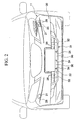
- FIG. 2 is a front view showing the vehicle that includes the bumper structure of the embodiment of the present invention.
- FIG. 3 is a perspective drawing showing the washer nozzle provided in the bumper structure of the embodiment of the present invention.
- FIG. 4 is a back view showing the bumper structure of the embodiment of the present invention.
- FIG. 5 is a perspective drawing viewing the bumper structure of the embodiment of the present invention from the back right side in the longitudinal direction of the vehicle.
- FIG. 6 is an enlarged perspective drawing viewing the essential components of the bumper structure of the embodiment of the present invention in the longitudinal direction of the vehicle from the right side.
- An embodiment of the bumper structure of the present invention will be explained with reference to the drawings. Note that in the following explanation, the term longitudinal refers to the front-to-back direction of the vehicle body.
- FIG. 1 is a drawing viewing a
bumper 11 and the vicinity thereof from the back side (rear side). In the front portion of the vehicle body, abumper beam 13 is provided along the widthwise direction of the vehicle on the front side of the frame-shapedradiator core support 12, and thebumper 11 is provided along the widthwise direction of the vehicle closer to the front than thisbumper beam 13. - As shown in FIG. 2, the
bumper 11 has abumper body 20 that extends in the widthwise direction of the vehicle and mainly forms the design surface of the vehicle.Nozzle openings 21 are formed in the upper portion of both ends of thebumper body 20 in the widthwise direction of the vehicle. In addition, an air intake opening 22 (an opening) extending in the widthwise direction of the vehicle is formed in the lower portion of thebumper body 20 in the center in the widthwise direction of the vehicle. Note that thebumper body 20 is integrally formed using a synthetic resin, and normally is used after the surface is coated. - Here, the
nozzle opening 21 allows thewasher nozzle 25 shown in FIG. 3 to project and retract. Thewasher nozzle 25 is for washing the headlight 24. Thewasher nozzle 25 includes abase portion 26 that is mounted on the back side of thebumper body 20 and anozzle body 27 that projects outside of thebumper body 20 from thebase portion 26 through the nozzle opening 21 and retracts therein. Acover 28 is provided on the upper end of thenozzle body 27, and the nozzle opening 21 is closed by thiscover 28 when thenozzle body 27 retracts into thebumper body 20. - As shown in FIG. 2 and FIG. 4, the
bumper 11 has abumper garnish 31 that is provided over the entire air intake opening 22, which extends in the lengthwise direction of thebumper body 20. Thisbumper garnish 31 has a shape that extends in the widthwise direction of the vehicle, conforming to the shape of the air intake opening 22. That is, thebumper garnish 31 is provided along the lengthwise direction of thebumper body 20. - As shown in FIG. 5, the
bumper garnish 31 includes aframe 32 that forms the outside edge thereof, atransverse plate 33 extending along the widthwise direction of the vehicle at the center of theframe 32 in the vertical direction, andvertical plates 34 extending along the vertical direction at a plurality of locations on theframe 32 in the widthwise direction of the vehicle. Among the plurality of portions enclosed by thetransverse plate 33 and thevertical plates 34, the center upper portions in the widthwise direction of the vehicle form the closedportions 35 and the remainder forms theopenings 36, which are open. - This
bumper garnish 31 is mounted on a plurality ofinstallation portions 38 provided on the upper edge of theframe 32 and on an installation portion (not illustrated) provided on the lower edge of the frame so as to be in contact with the back surface of the peripheral edge of the air intake opening 22 of thebumper body 20. Note that, as shown in FIG. 1, thebumper garnish 31 is disposed below thebumper body 13. - Clamping devices (a retaining device) 42 that conform to the shape of the
washer hose 41 are formed in plurality on thebumper garnish 31 at predetermined intervals in the widthwise direction of the vehicle. Theclamping devices 42 are for retaining the washer hose (pipe member) 41 along the lower edge of theframe 32. Thewasher hose 41 communicates with thewasher nozzle 25 described above and supplies washing liquid. In addition, the slit portions (a retaining device) 43 that retain thewasher hose 41 are formed in the widthwise direction outside theclamping devices 42 at both ends in the widthwise direction of the vehicle. That is, theclamping devices 42, which conform to the shape of thewasher hose 41, and slitportions 43, which are closer to the end portions than theclamping devices 42, are formed at the ends of thebumper garnish 31 in the lengthwise direction. - As shown in FIG. 6, the cross-section of each of the
clamping devices 42 perpendicular to the widthwise direction of the vehicle opens upward so as to conform to the shape of thewasher hose 41, and at the same time, the upper end forms a curved shape that is closer to theframe 32 than the bottom thereof, and this cross-section forms a shape that is continuous in the widthwise direction of the vehicle. In addition, the circularshaped washer hose 41 is pushed downward from the top into each of theclamping devices 42 to an orientation that extends in the widthwise direction of the vehicle, and thereby each of theclamping devices 42 retains the circumferential surface of thewasher hose 41 against theframe 32. In this state, theclamping devices 42 retain thewasher hose 41 oriented along the lower edge of theframe 32 of thebumper garnish 31 that extends in the lengthwise direction and in proximity to the lower edge thereof. - The
slit portions 43 are formed in outside regions, as viewed in the widthwise direction of the vehicle, of theframes 32 that respectively house clampingdevices 42 located at both ends in the widthwise direction of the vehicle at intervals that are narrower than the intervals betweenadjacent clamping devices 42. Theslit portions 43 have a shape that passes through theframe 32 in a substantially longitudinal direction of the vehicle and exit at the bottom. In theframe 32, the outer edges of theslit portions 43 in the widthwise direction of the vehicle are offset more than the inner edges of theslit portions 43 in the widthwise direction of the vehicle on the rear side in the lengthwise direction of the vehicle. As a result, thewasher hose 41 that is pressed into theslit portions 43 from below is retained in an orientation substantially along the lengthwise direction of thebumper garnish 31. Note that the width of the bottom of theslit portions 43 is narrower than the width of the top so that thewasher hose 41 can be retained at the top. - The
bumper garnish 31 is integrally formed using a synthetic resin, and is used without coating. Here, during integral molding, theclamping devices 42 and theslit portions 43 that retain thewasher hose 41 are both integrally formed on thebumper garnish 31. - When arranging the
washer hose 41 on thebumper 11 having thebumper garnish 31 and thebumper body 20 described above, theentire washer hose 41 is aligned in the widthwise direction of the vehicle. By inserting both ends thereof through theslit portions 43, thewasher hose 41 is guided to the outside (front side) of thebumper garnish 31, and thereby the center portion of thewasher hose 41 provided inside (rear side) thebumper garnish 31 is retained by being inserted into the plurality ofclamps 42. As a result, thewasher hose 41, which is retained by theclamps 42 so as to be oriented along the lower edge portion of thebumper garnish 31 that extends in the lengthwise direction, is arranged along and in proximity to the lower edge portion of thebumper garnish 31 that extends in the lengthwise direction. In addition, a portion of thewasher hose 41 that exits through theslit portions 43 to the front of thebumper garnish 31 and extends to the outside in the widthwise direction of the vehicle passes between thebumper body 20 and theradiator core support 12. - In addition, at both ends of in the widthwise direction of the vehicle, the
washer hose 41 described above communicates with thewasher nozzle 25 via anotherseparate washer hose 45, and at the same time, communicates with awasher pump 46 after branching from the communication position of thewasher hose 41 and one of thewasher hoses 45, and further communicates with a washing liquid supply side (not illustrated). - According to the present embodiment described above, clamping
devices 42 and slitportions 43 that retain thewasher hose 41 are integrally formed on thebumper garnish 31 that is provided in theair intake opening 22 formed in thebumper body 20, and thus thewasher hose 41 can be retained in the integrally formed clampingdevices 42 and theslit portions 43, and separate clips become unnecessary. Therefore, it is possible to reduce the number of parts, possible to reduce the mounting time, and possible to improve the appearance after the pipe member is arranged. In addition, theclamping devices 42 and theslit portions 43 that retain thewasher hose 41 are integrally formed on thebumper garnish 31, and thus even if shrinkage defects occur in thebumper garnish 31 that originate in the formation thereof, thebumper body 20, which mainly forms the design surface, will not be affected. Therefore, it is possible to prevent degradation in the quality of the external appearance of thebumper body 20. - In addition, the
washer hose 41 is arranged along the lengthwise direction of thebumper garnish 31 in theclamping devices 42 and theslit portions 43 that retain thewasher hose 41 oriented along the lower edge of thebumper garnish 31 extending in the lengthwise direction. Thereby, the retaining orientation and the arrangement direction are identical, and thus it is possible to arrange thewasher hose 41 easily. Therefore, large bends and the like do not occur in thewasher hose 41, and the flow of liquid therein is not hindered. - Furthermore, at the ends of the
bumper garnish 31 in the lengthwise direction, after thewasher hose 41 is retained in theclamps 42 that conform to the shape thereof, it is inserted throughslit portions 43 closer to ends and guided to the outside. Thus, thewasher hose 41 can be guided to the outside while avoiding the center portion in the lengthwise direction, whose design layout is difficult, and the arrangement can be carried out easily. Therefore, large bends do not occur in thewasher hose 41, and the flow of the liquid therein is not hindered. In addition, after thewasher hose 41 is retained in thebumper garnish 31 by theclamping devices 42, it is passed through theslit portions 43. Thus, thewasher hose 41 can be guided to the outside from theslit portions 43 without becoming separated from thebumper garnish 31. - In addition, the
washer hose 41 is provided along the lower edge portion of thebumper garnish 31 provided under thebumper beam 13, and thus it is possible to arrange thewasher hose 41 avoiding thebumper beam 13. - While preferred embodiments of the invention have been described and illustrated above, it should be understood that these are exemplary of the invention and are not to be considered as limiting. Additions, omissions, substitutions, and other modifications can be made without departing from the spirit or scope of the present invention. Accordingly, the invention is not to be considered as being limited by the foregoing description, and is only limited by the scope of the appended claims.
Claims (4)
- A bumper structure comprising:a bumper body (20);a bumper garnish (31) disposed in an opening (22) defined in the bumper body (20); anda retaining device (42, 43) integrally formed in the bumper garnish (31) and retaining a pipe member (41).
- A bumper structure according to claim 1, wherein the bumper garnish (31) is disposed along a lengthwise direction of the bumper body (20), and the retaining device (42, 43) retains the pipe member (41) in an arrangement in which the pipe member (41) is arranged along a lengthwise direction of the bumper garnish (31) and along an edge portion of the bumper garnish (31) that extends in the lengthwise direction of the bumper garnish (31).
- A bumper structure according to claim 2,wherein the retaining device (42, 43) comprises, in a lengthwise end region of the bumper garnish (31), a clamping device (42) that conforms to a shape of the pipe member (41), and a slit portion (43) that is located closer to an end of the bumper garnish (31) than the clamping device (42), andwherein the pipe member (41) is arranged by being retained by the clamping device (42) and being inserted through the slit portion (43).
- A bumper structure according to any one of claims 1 to 3, wherein the bumper garnish (31) is disposed below of a bumper beam (13) that is connected to a body frame, and the pipe member (41) is arranged along a lower edge portion of the bumper garnish (31).
Applications Claiming Priority (1)
| Application Number | Priority Date | Filing Date | Title |
|---|---|---|---|
| JP2004196658A JP4358051B2 (en) | 2004-07-02 | 2004-07-02 | Bumper structure |
Publications (2)
| Publication Number | Publication Date |
|---|---|
| EP1612107A1 true EP1612107A1 (en) | 2006-01-04 |
| EP1612107B1 EP1612107B1 (en) | 2006-11-22 |
Family
ID=34937727
Family Applications (1)
| Application Number | Title | Priority Date | Filing Date |
|---|---|---|---|
| EP20050014187 Expired - Lifetime EP1612107B1 (en) | 2004-07-02 | 2005-06-30 | Bumper structure |
Country Status (3)
| Country | Link |
|---|---|
| EP (1) | EP1612107B1 (en) |
| JP (1) | JP4358051B2 (en) |
| DE (1) | DE602005000277T2 (en) |
Families Citing this family (3)
| Publication number | Priority date | Publication date | Assignee | Title |
|---|---|---|---|---|
| DE102009056016B4 (en) * | 2009-11-27 | 2024-10-02 | Dr. Ing. H.C. F. Porsche Aktiengesellschaft | planking part |
| JP2013256150A (en) * | 2012-06-11 | 2013-12-26 | Faltec Co Ltd | Front grill structure |
| DE102019122202B4 (en) | 2019-08-19 | 2023-06-07 | Webasto SE | Roof module with environment sensor for autonomous or semi-autonomous driving |
Citations (4)
| Publication number | Priority date | Publication date | Assignee | Title |
|---|---|---|---|---|
| US4318510A (en) * | 1978-11-20 | 1982-03-09 | Nissan Motor Company, Limited | Washer system for an automotive vehicle |
| JPH0761330A (en) * | 1993-08-27 | 1995-03-07 | Toyota Motor Corp | Head hose cleaner cleaner hose holding structure |
| JPH07179157A (en) | 1993-12-24 | 1995-07-18 | Nissan Motor Co Ltd | Automotive bumper |
| JPH08104193A (en) * | 1994-10-03 | 1996-04-23 | Nishikawa Kasei Co Ltd | Car bumper structure |
-
2004
- 2004-07-02 JP JP2004196658A patent/JP4358051B2/en not_active Expired - Fee Related
-
2005
- 2005-06-30 EP EP20050014187 patent/EP1612107B1/en not_active Expired - Lifetime
- 2005-06-30 DE DE200560000277 patent/DE602005000277T2/en not_active Expired - Lifetime
Patent Citations (4)
| Publication number | Priority date | Publication date | Assignee | Title |
|---|---|---|---|---|
| US4318510A (en) * | 1978-11-20 | 1982-03-09 | Nissan Motor Company, Limited | Washer system for an automotive vehicle |
| JPH0761330A (en) * | 1993-08-27 | 1995-03-07 | Toyota Motor Corp | Head hose cleaner cleaner hose holding structure |
| JPH07179157A (en) | 1993-12-24 | 1995-07-18 | Nissan Motor Co Ltd | Automotive bumper |
| JPH08104193A (en) * | 1994-10-03 | 1996-04-23 | Nishikawa Kasei Co Ltd | Car bumper structure |
Non-Patent Citations (3)
| Title |
|---|
| PATENT ABSTRACTS OF JAPAN vol. 1995, no. 06 31 July 1995 (1995-07-31) * |
| PATENT ABSTRACTS OF JAPAN vol. 1995, no. 10 30 November 1995 (1995-11-30) * |
| PATENT ABSTRACTS OF JAPAN vol. 1996, no. 08 30 August 1996 (1996-08-30) * |
Also Published As
| Publication number | Publication date |
|---|---|
| DE602005000277T2 (en) | 2007-03-01 |
| JP4358051B2 (en) | 2009-11-04 |
| EP1612107B1 (en) | 2006-11-22 |
| DE602005000277D1 (en) | 2007-01-04 |
| JP2006015906A (en) | 2006-01-19 |
Similar Documents
| Publication | Publication Date | Title |
|---|---|---|
| US7354082B2 (en) | Bumper structure for vehicle | |
| US5527081A (en) | Convertible vehicle topwell drainage arrangement | |
| JP6797754B2 (en) | Camera unit | |
| CN103112378A (en) | Headrest structure | |
| JP2003072475A (en) | Vehicle roof rack fixing device | |
| US8151809B2 (en) | Cleaning apparatus for vehicle lamp | |
| US6598924B2 (en) | Holding and mounting device and method for a front/rear panel of a vehicle | |
| US20130105638A1 (en) | Supply system for supplying passengers in a passenger compartment of a vehicle | |
| EP1612107B1 (en) | Bumper structure | |
| KR102730544B1 (en) | Inlet duct structure for vehicle battery system | |
| CN102862526B (en) | The leakproofing material fixed sturcture of the cover plate ornamental parts of vehicle | |
| CN101456352A (en) | Structure for mounting radiator to front-end module carrier | |
| CN113386695A (en) | Rear bumper installing system and vehicle | |
| JP3692280B2 (en) | Cover member mounting structure for vehicle roof groove | |
| JP5630201B2 (en) | Split windows for vehicles | |
| US8991910B2 (en) | Water drain valve for the water box of a motor vehicle | |
| US7270363B1 (en) | Golf car splash guard | |
| CN103043108A (en) | Column structure of car | |
| WO2024068401A1 (en) | Air guiding assembly and front bumper assembly | |
| CN211001220U (en) | A car bumper support structure | |
| US20050211486A1 (en) | Filler neck for motor vehicle fuel tank | |
| CN110770075B (en) | Motor vehicle equipped with a central console comprising an electronic box | |
| US10434957B2 (en) | Vehicle interior structure | |
| CN220017894U (en) | Bottle holders and refrigeration equipment | |
| CN217274747U (en) | Pipe casting die and air conditioner with same |
Legal Events
| Date | Code | Title | Description |
|---|---|---|---|
| PUAI | Public reference made under article 153(3) epc to a published international application that has entered the european phase |
Free format text: ORIGINAL CODE: 0009012 |
|
| AK | Designated contracting states |
Kind code of ref document: A1 Designated state(s): AT BE BG CH CY CZ DE DK EE ES FI FR GB GR HU IE IS IT LI LT LU MC NL PL PT RO SE SI SK TR |
|
| AX | Request for extension of the european patent |
Extension state: AL BA HR LV MK YU |
|
| 17P | Request for examination filed |
Effective date: 20060224 |
|
| GRAP | Despatch of communication of intention to grant a patent |
Free format text: ORIGINAL CODE: EPIDOSNIGR1 |
|
| AKX | Designation fees paid |
Designated state(s): DE GB |
|
| GRAS | Grant fee paid |
Free format text: ORIGINAL CODE: EPIDOSNIGR3 |
|
| GRAA | (expected) grant |
Free format text: ORIGINAL CODE: 0009210 |
|
| AK | Designated contracting states |
Kind code of ref document: B1 Designated state(s): DE GB |
|
| REG | Reference to a national code |
Ref country code: GB Ref legal event code: FG4D |
|
| REF | Corresponds to: |
Ref document number: 602005000277 Country of ref document: DE Date of ref document: 20070104 Kind code of ref document: P |
|
| PLBE | No opposition filed within time limit |
Free format text: ORIGINAL CODE: 0009261 |
|
| STAA | Information on the status of an ep patent application or granted ep patent |
Free format text: STATUS: NO OPPOSITION FILED WITHIN TIME LIMIT |
|
| 26N | No opposition filed |
Effective date: 20070823 |
|
| PGFP | Annual fee paid to national office [announced via postgrant information from national office to epo] |
Ref country code: DE Payment date: 20100625 Year of fee payment: 6 Ref country code: GB Payment date: 20100630 Year of fee payment: 6 |
|
| GBPC | Gb: european patent ceased through non-payment of renewal fee |
Effective date: 20110630 |
|
| PG25 | Lapsed in a contracting state [announced via postgrant information from national office to epo] |
Ref country code: DE Free format text: LAPSE BECAUSE OF NON-PAYMENT OF DUE FEES Effective date: 20120103 |
|
| REG | Reference to a national code |
Ref country code: DE Ref legal event code: R119 Ref document number: 602005000277 Country of ref document: DE Effective date: 20120103 |
|
| PG25 | Lapsed in a contracting state [announced via postgrant information from national office to epo] |
Ref country code: GB Free format text: LAPSE BECAUSE OF NON-PAYMENT OF DUE FEES Effective date: 20110630 |