EP1612084B1 - Electrically assisted bicycle - Google Patents
Electrically assisted bicycle Download PDFInfo
- Publication number
- EP1612084B1 EP1612084B1 EP05014180A EP05014180A EP1612084B1 EP 1612084 B1 EP1612084 B1 EP 1612084B1 EP 05014180 A EP05014180 A EP 05014180A EP 05014180 A EP05014180 A EP 05014180A EP 1612084 B1 EP1612084 B1 EP 1612084B1
- Authority
- EP
- European Patent Office
- Prior art keywords
- motor
- state
- battery
- bicycle
- control unit
- Prior art date
- Legal status (The legal status is an assumption and is not a legal conclusion. Google has not performed a legal analysis and makes no representation as to the accuracy of the status listed.)
- Expired - Fee Related
Links
Images

Classifications
-
- B—PERFORMING OPERATIONS; TRANSPORTING
- B60—VEHICLES IN GENERAL
- B60L—PROPULSION OF ELECTRICALLY-PROPELLED VEHICLES; SUPPLYING ELECTRIC POWER FOR AUXILIARY EQUIPMENT OF ELECTRICALLY-PROPELLED VEHICLES; ELECTRODYNAMIC BRAKE SYSTEMS FOR VEHICLES IN GENERAL; MAGNETIC SUSPENSION OR LEVITATION FOR VEHICLES; MONITORING OPERATING VARIABLES OF ELECTRICALLY-PROPELLED VEHICLES; ELECTRIC SAFETY DEVICES FOR ELECTRICALLY-PROPELLED VEHICLES
- B60L7/00—Electrodynamic brake systems for vehicles in general
- B60L7/10—Dynamic electric regenerative braking
- B60L7/18—Controlling the braking effect
-
- B—PERFORMING OPERATIONS; TRANSPORTING
- B60—VEHICLES IN GENERAL
- B60L—PROPULSION OF ELECTRICALLY-PROPELLED VEHICLES; SUPPLYING ELECTRIC POWER FOR AUXILIARY EQUIPMENT OF ELECTRICALLY-PROPELLED VEHICLES; ELECTRODYNAMIC BRAKE SYSTEMS FOR VEHICLES IN GENERAL; MAGNETIC SUSPENSION OR LEVITATION FOR VEHICLES; MONITORING OPERATING VARIABLES OF ELECTRICALLY-PROPELLED VEHICLES; ELECTRIC SAFETY DEVICES FOR ELECTRICALLY-PROPELLED VEHICLES
- B60L50/00—Electric propulsion with power supplied within the vehicle
- B60L50/20—Electric propulsion with power supplied within the vehicle using propulsion power generated by humans or animals
-
- B—PERFORMING OPERATIONS; TRANSPORTING
- B60—VEHICLES IN GENERAL
- B60L—PROPULSION OF ELECTRICALLY-PROPELLED VEHICLES; SUPPLYING ELECTRIC POWER FOR AUXILIARY EQUIPMENT OF ELECTRICALLY-PROPELLED VEHICLES; ELECTRODYNAMIC BRAKE SYSTEMS FOR VEHICLES IN GENERAL; MAGNETIC SUSPENSION OR LEVITATION FOR VEHICLES; MONITORING OPERATING VARIABLES OF ELECTRICALLY-PROPELLED VEHICLES; ELECTRIC SAFETY DEVICES FOR ELECTRICALLY-PROPELLED VEHICLES
- B60L50/00—Electric propulsion with power supplied within the vehicle
- B60L50/40—Electric propulsion with power supplied within the vehicle using propulsion power supplied by capacitors
-
- B—PERFORMING OPERATIONS; TRANSPORTING
- B60—VEHICLES IN GENERAL
- B60L—PROPULSION OF ELECTRICALLY-PROPELLED VEHICLES; SUPPLYING ELECTRIC POWER FOR AUXILIARY EQUIPMENT OF ELECTRICALLY-PROPELLED VEHICLES; ELECTRODYNAMIC BRAKE SYSTEMS FOR VEHICLES IN GENERAL; MAGNETIC SUSPENSION OR LEVITATION FOR VEHICLES; MONITORING OPERATING VARIABLES OF ELECTRICALLY-PROPELLED VEHICLES; ELECTRIC SAFETY DEVICES FOR ELECTRICALLY-PROPELLED VEHICLES
- B60L50/00—Electric propulsion with power supplied within the vehicle
- B60L50/50—Electric propulsion with power supplied within the vehicle using propulsion power supplied by batteries or fuel cells
- B60L50/51—Electric propulsion with power supplied within the vehicle using propulsion power supplied by batteries or fuel cells characterised by AC-motors
-
- B—PERFORMING OPERATIONS; TRANSPORTING
- B60—VEHICLES IN GENERAL
- B60L—PROPULSION OF ELECTRICALLY-PROPELLED VEHICLES; SUPPLYING ELECTRIC POWER FOR AUXILIARY EQUIPMENT OF ELECTRICALLY-PROPELLED VEHICLES; ELECTRODYNAMIC BRAKE SYSTEMS FOR VEHICLES IN GENERAL; MAGNETIC SUSPENSION OR LEVITATION FOR VEHICLES; MONITORING OPERATING VARIABLES OF ELECTRICALLY-PROPELLED VEHICLES; ELECTRIC SAFETY DEVICES FOR ELECTRICALLY-PROPELLED VEHICLES
- B60L7/00—Electrodynamic brake systems for vehicles in general
- B60L7/24—Electrodynamic brake systems for vehicles in general with additional mechanical or electromagnetic braking
- B60L7/26—Controlling the braking effect
-
- B—PERFORMING OPERATIONS; TRANSPORTING
- B62—LAND VEHICLES FOR TRAVELLING OTHERWISE THAN ON RAILS
- B62M—RIDER PROPULSION OF WHEELED VEHICLES OR SLEDGES; POWERED PROPULSION OF SLEDGES OR SINGLE-TRACK CYCLES; TRANSMISSIONS SPECIALLY ADAPTED FOR SUCH VEHICLES
- B62M6/00—Rider propulsion of wheeled vehicles with additional source of power, e.g. combustion engine or electric motor
- B62M6/40—Rider propelled cycles with auxiliary electric motor
- B62M6/45—Control or actuating devices therefor
-
- B—PERFORMING OPERATIONS; TRANSPORTING
- B62—LAND VEHICLES FOR TRAVELLING OTHERWISE THAN ON RAILS
- B62M—RIDER PROPULSION OF WHEELED VEHICLES OR SLEDGES; POWERED PROPULSION OF SLEDGES OR SINGLE-TRACK CYCLES; TRANSMISSIONS SPECIALLY ADAPTED FOR SUCH VEHICLES
- B62M6/00—Rider propulsion of wheeled vehicles with additional source of power, e.g. combustion engine or electric motor
- B62M6/80—Accessories, e.g. power sources; Arrangements thereof
- B62M6/90—Batteries
-
- B—PERFORMING OPERATIONS; TRANSPORTING
- B60—VEHICLES IN GENERAL
- B60L—PROPULSION OF ELECTRICALLY-PROPELLED VEHICLES; SUPPLYING ELECTRIC POWER FOR AUXILIARY EQUIPMENT OF ELECTRICALLY-PROPELLED VEHICLES; ELECTRODYNAMIC BRAKE SYSTEMS FOR VEHICLES IN GENERAL; MAGNETIC SUSPENSION OR LEVITATION FOR VEHICLES; MONITORING OPERATING VARIABLES OF ELECTRICALLY-PROPELLED VEHICLES; ELECTRIC SAFETY DEVICES FOR ELECTRICALLY-PROPELLED VEHICLES
- B60L2200/00—Type of vehicles
- B60L2200/12—Bikes
-
- B—PERFORMING OPERATIONS; TRANSPORTING
- B60—VEHICLES IN GENERAL
- B60L—PROPULSION OF ELECTRICALLY-PROPELLED VEHICLES; SUPPLYING ELECTRIC POWER FOR AUXILIARY EQUIPMENT OF ELECTRICALLY-PROPELLED VEHICLES; ELECTRODYNAMIC BRAKE SYSTEMS FOR VEHICLES IN GENERAL; MAGNETIC SUSPENSION OR LEVITATION FOR VEHICLES; MONITORING OPERATING VARIABLES OF ELECTRICALLY-PROPELLED VEHICLES; ELECTRIC SAFETY DEVICES FOR ELECTRICALLY-PROPELLED VEHICLES
- B60L2250/00—Driver interactions
- B60L2250/16—Driver interactions by display
-
- Y—GENERAL TAGGING OF NEW TECHNOLOGICAL DEVELOPMENTS; GENERAL TAGGING OF CROSS-SECTIONAL TECHNOLOGIES SPANNING OVER SEVERAL SECTIONS OF THE IPC; TECHNICAL SUBJECTS COVERED BY FORMER USPC CROSS-REFERENCE ART COLLECTIONS [XRACs] AND DIGESTS
- Y02—TECHNOLOGIES OR APPLICATIONS FOR MITIGATION OR ADAPTATION AGAINST CLIMATE CHANGE
- Y02T—CLIMATE CHANGE MITIGATION TECHNOLOGIES RELATED TO TRANSPORTATION
- Y02T10/00—Road transport of goods or passengers
- Y02T10/60—Other road transportation technologies with climate change mitigation effect
- Y02T10/70—Energy storage systems for electromobility, e.g. batteries
Definitions
- the present invention relates to a method for controlling a regenerative state of a motor of an electrically assisted bicycle which is driven with human power and with auxiliary power afforded by an assisting power device.
- auxiliary power given by an electric motor or like power device is used for assisting in running in addition to the force produced by the rider by pedaling so as to reduce the pedaling force to be produced by the rider.
- the electrically assisted bicycles disclosed in these publications are adapted to perform regenerative braking when the brake lever is manipulated. Accordingly, the charging by regenerative braking can be effected only when the brake is actuated on descents, failing to fully increase the cycling distance.
- EP 0 994 015 A2 is concerned with a bicycle with power assisting function that have a human power drive mechanism for producing a drive force with human power, a battery adapted for discharging and recharging, an electric power drive mechanism including an electric motor for producing a drive force with electric power output from the battery, speed detecting means for detecting the running speed of the bicycle and a control unit for controlling the electric motor of the power drive mechanism.
- the electric motor can be operated as an electric generator for utilizing part of regenerated electric energy to recharge the battery.
- a regenerating mode is set to regenerate electric energy.
- EP 0 798 204 A1 discloses a regeneration control device for a bicycle with an auxiliary motor wherein the auxiliary motor can be used as a generator for generating electric power to recharge the battery.
- the re-generation control device judges the necessity of regeneration based on the bicycle speed detected by a bicycle speed detection means and pressing force detected by pressing force detection means and changes the motor to a state of regeneration according to the detected speed and pressing force.
- the regenerating state is set when the bicycle speed is higher than a certain value and the pressing force is lower than a certain level.
- An object of the present invention which has been accomplished to solve the above problem, is to provide a method for controlling a regenerative state of a motor of an electrically assisted bicycle to remarkably increase the cycling distance by effectively utilizing auxiliary power.
- the battery can be charged by effectively utilizing the running energy of the bicycle, whereby the cycling distance can be increased remarkably.
- the battery is charged only while the bicycle is running at a speed not lower than the predetermined value, and the bicycle is assisted with the drive force of the electric power drive mechanism when running at a speed below the predetermined value. Accordingly, no trouble occurs in the stability of running at a low speed range.
- the regenerative state is changed over to the nonregenerative state, the running efficiency will not be impaired. Since a changeover takes place when a lower running speed remains for the specified period of time, a changeover from the regenerative state to the nonregenerative state and vice verse will not occur frequently, whereby a stabilized state of running can be ensured.
- a changeover between an "economical charging” mode wherein the motor is set in the regenerative state when the running speed detected by the speed detecting means is not lower than the predetermined value and a "standard mode" wherein the motor is set in the nonregenerative state irrespective of the running speed detected by the speed detecting means is effected by changeover means.
- the battery can be charged by effectively utilizing the running energy of the bicycle when the "economical charging” mode is selected, whereby the cycling distance can be increased remarkably.
- the battery is charged in the "economical charging” mode only while the bicycle is running at a speed not lower than the predetermined value, and the bicycle is assisted with the drive force of the electric power drive mechanism when running at a speed below the predetermined value. Accordingly, no trouble occurs in the stability of running at a low speed range.
- the rider can select the "economical charging" mode or the "standard” mode as required, with the result that the bicycle is usable with improved convenience.
- charging of the battery with the power generated by the motor is interrupted by the control unit when the remaining capacity of the battery is not lower than a specified value.
- the control unit interrupts the charging of the battery with the power generated by the motor. This obviates the likelihood of the battery becoming overcharged.
- charging of the battery with the power generated by the motor is interrupted by the control unit when the running speed detected by the speed detecting means is not lower than a given value.
- the control unit interrupts the charging of the battery with the power generated by the motor. This obviates the likelihood of the battery becoming overcharged.
- regenerative braking upon detecting braking to charge the battery is effected by the control unit. Since the control unit performs regenerative braking upon detecting the application of the brake, improved safety will result, while the battery can be charged by the regenerative braking, whereby the cycling distance can further be increased.
- the pedaling force of the bicycle is detected by means of a pedal torque sensor, and the regenerative state is changed over by the control unit to the nonregenerative state when the running speed detected by the speed detecting means is below the predetermined value and when the pedaling force detected by the pedal torque sensor is not lower than a specified value.
- the regenerative state is changed over to the nonregenerative state when the running speed drops and when the pedaling force is not lower than the specified value.
- the electric power to be generated by the motor is set at a greater value as the running speed detected by the speed detecting means increases.
- the battery can be charged to a greater level utilizing the excessive force of the rider, consequently serving to further increase the cycling distance.
- the auxiliary power of the electric power drive mechanism in the nonregenerative state is set by the control unit (13) at a lower value when selecting the "economical charging” mode than when selecting the "standard” mode.
- the auxiliary power of the electric power drive mechanism in the nonregenerative state is set at a lower value when in the "economical charging” mode than when in the "standard” mode, so that the consumption of the power of the battery can be diminished to result in a further increase in the cycling distance.
- Electrically assisted bicycles comprise a human power drive mechanism for transmitting the pedaling force of the rider from pedals to a wheel via a crank, chain, etc., an electric power drive mechanism including an electric motor serving as a drive source for assisting the pedaling force of the human power mechanism and a battery which is adapted for discharging and recharging for supplying electric power to the electric power drive mechanism.
- FIG. 1 is a block diagram showing control means of an electrically assisting bicycle
- FIG. 2 is a diagram showing a charge-discharge circuit of the bicycle.
- an electric motor 1 is coupled to an unillustrated bicycle wheel for transmitting power thereto.
- the motor rotates the wheel with the electric power supplied from a battery 3 through the charge-discharge circuit 2.
- the battery 3 is charged with the power generated utilizing the rotation of the wheel.
- the state in which the wheel is rotated with the electric power supplied from the battery 3 will hereinafter be referred to as the "nonregenerative state,” and the state in which the battery 3 is charged with the power generated utilizing the rotation of the wheel as the "regenerative state.”
- Indicated at 4 is a torque sensor for detecting the pedaling force exerted on the pedals.
- a speed detecting means 5 detects the running speed of the bicycle from the rotational speed of the motor 1.
- a braking sensor 6 detects the actuation of the brake of the bicycle.
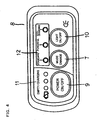
- a mode setting switch 7 is provided on a manipulation unit 8 mountable in the vicinity of the handle and to be described later, and is used by the rider.
- FIG. 3 shows the manipulation unit 8 provided with the mode setting switch 7.
- the bicycle is set for one of operating modes, i.e., "standard,” “powerful” and “economical charging” (hereinafter referred to briefly as “eco-charging").
- the manipulation unit 8 is provided, in addition to the mode setting switch 7, with a power source switch 9, lighting switch 10 for on-off controlling a light serving as the unillustrated headlight of the bicycle, battery empty indicator 11, and mode indicator 12 for indicating the mode selected by the mode setting switch 7.
- Indicated at 13 is a control unit for receiving signals from the torque sensor 4, speed detecting means 5, braking sensor 6, mode setting switch 7, power source switch 9 and lighting switch 10 and controlling the charge-discharge circuit 2, battery empty indicator 11, mode indicator 12 and the unillustrated light.
- a MOSFET circuit 14 is provided between the motor 1 and the battery 3 for controlling the motor 1.
- An FET 15 is connected between the MOSFET circuit 14 and the positive electrode of the battery 3.
- the MOSFET circuit 14 and the FET 15 are controlled by a drive circuit 16 of the control unit 13. Indicated at 17 is a capacitor, and at 18 a resistor.
- the drive circuit 16 turns off the FET 15, preventing the electromotive force of the motor 1 from increasing and charging the battery 3. If the electromotive force of the motor 1 increases during running at a high speed, and the output voltage of the battery 3 becomes 24 V or higher according to the embodiment, the battery 3 is likely to be charged and become overcharged. Accordingly, when the running speed is at least a given value, the FET 15 is turned off to prevent overcharging.
- the given speed is a value sufficiently higher than a predetermined speed of step 6 to be described later and at least a speed at which the battery 3 is undesirably charged with the electromotive force of the motor 1.
- the control unit 13 further detects the remaining capacity of the battery 3, and when the remaining capacity is not smaller than a predetermined value, i.e., at least 90% according to the embodiment, the control unit 13 turns off the FET 15 to prevent the battery 3 from being overcharged with the power to be generated by the motor 1 as when the brake is actuated. Overcharging is prevented in this way even in the case where any of the "standard” mode, "powerful” mode and “eco-charging” mode is selected.
- the FET 15 is connected between the battery 3 and the MOSFET circuit 14 for controlling the connection between the battery 3 and the MOSFET 14, whereas other component capable of controlling the connection, such as a relay, may alternatively be used.
- the torque sensor 4 detects the pedaling force, whereupon the motor 1 is driven in accordance with the pedaling force to add an auxiliary force of the motor 1 to the human pedaling force and run the bicycle.
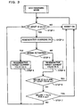
- the bicycle speed setting switch 7 When the "eco-charging" mode is set by the mode setting switch 7, an inquiry is made as to whether the bicycle speed is not lower than a predetermined value, i.e., at least 12 kg/h in the present embodiment, with reference to the speed detecting means 5 as shown in the flow chart of FIG. 3 (step 1). If the running speed is less than the predetermined value, the bicycle is brought into a nonregenerative state to add to the pedaling force auxiliary power of the motor 1 in accordance with the pedaling force for running the bicycle. This auxiliary power is set 50% of the power in the "standard" mode to diminish the consumption of the battery 3.
- a predetermined value i.e., at least 12 kg/h in the present embodiment
- step 1 When the speed is found to be at least the predetermined value in step 1, the mode is changed over to the regenerative state, in which power is generated by the motor 1 to charge the battery 3 (step 2). At this time, an inquiry is made as to whether the brake is applied (step 3). When the inquiry is answered in the negative, the bicycle is in the usual state of running. If great current is produced, running load increases, so that a current value of 0.8 A is generated for charging the battery 3 (step 4). If the brake is on, regenerative braking can be utilized to obtain great current. Current of up to 6 A is therefore generated for charging the battery 3 (step 5). The greater the speed, the greater the current value to be generation by this regenerative braking is and the greater the braking force feels, so that improved safety can be achieved on descents.
- the regenerative state is promptly changed over to the nonregenerative state since the rider will be greatly burdened in the regenerative state (step 6).
- the regenerative state is changed over to the nonregenerative state in the case where the bicycle remains at a speed less than the predetermined value, i.e., less than 11 km/h according to the present embodiment, for a specified period of time, i.e., for 3 seconds (sep 7). This specified period of time is provided to avoid frequent changeovers between the regenerative state and the nonregenerative state.
- the auxiliary power of the motor 1 is greater than in the "eco-charging” mode, the motor is not brought into the regenerative state but is held in the nonregenerative state even if the speed is not lower than the predetermined value.
- the motor is brought into the regenerative state only when the brake is actuated.
- the auxiliary power of the motor 1 is greater than in the "standard” mode to lessen the burden on the rider.
- the charging current value may be increased as the running speed increases.
- the speed detecting means 5 is adapted to detect the running speed by detecting the rotation of the motor 1, the rotation of the wheel of the bicycle may be detected for the calculation of the running speed, or other detecting structure may be used.
Landscapes
- Engineering & Computer Science (AREA)
- Transportation (AREA)
- Mechanical Engineering (AREA)
- Power Engineering (AREA)
- Chemical & Material Sciences (AREA)
- Combustion & Propulsion (AREA)
- Life Sciences & Earth Sciences (AREA)
- Sustainable Development (AREA)
- Sustainable Energy (AREA)
- Physics & Mathematics (AREA)
- Electromagnetism (AREA)
- Electric Propulsion And Braking For Vehicles (AREA)
Description
- The present invention relates to a method for controlling a regenerative state of a motor of an electrically assisted bicycle which is driven with human power and with auxiliary power afforded by an assisting power device.
- Electrically assisted bicycles are known in recent years wherein auxiliary power given by an electric motor or like power device is used for assisting in running in addition to the force produced by the rider by pedaling so as to reduce the pedaling force to be produced by the rider.
- With such electrically assisted bicycles, regenerative braking is performed on descents to charge a battery with the power generated by regenerative braking. This realizes savings in energy, resulting in a great increase in the distance of cycling by effectively utilizing the auxiliary power with the capacity of the battery remaining unchanged although such an increase is unavailable if the regenerative braking is not practiced (see, for example, the publications of
JP-A No. 9-254861 JP-A No. 10-147150 - The electrically assisted bicycles disclosed in these publications are adapted to perform regenerative braking when the brake lever is manipulated. Accordingly, the charging by regenerative braking can be effected only when the brake is actuated on descents, failing to fully increase the cycling distance.
-
EP 0 994 015 A2 is concerned with a bicycle with power assisting function that have a human power drive mechanism for producing a drive force with human power, a battery adapted for discharging and recharging, an electric power drive mechanism including an electric motor for producing a drive force with electric power output from the battery, speed detecting means for detecting the running speed of the bicycle and a control unit for controlling the electric motor of the power drive mechanism. The electric motor can be operated as an electric generator for utilizing part of regenerated electric energy to recharge the battery. - When the running speed of the bicycle is higher than a predetermined level while the bicycle is running on the flat terrain, a regenerating mode is set to regenerate electric energy.
-
EP 0 798 204 A1 discloses a regeneration control device for a bicycle with an auxiliary motor wherein the auxiliary motor can be used as a generator for generating electric power to recharge the battery. The re-generation control device judges the necessity of regeneration based on the bicycle speed detected by a bicycle speed detection means and pressing force detected by pressing force detection means and changes the motor to a state of regeneration according to the detected speed and pressing force. In particular, the regenerating state is set when the bicycle speed is higher than a certain value and the pressing force is lower than a certain level. - An object of the present invention, which has been accomplished to solve the above problem, is to provide a method for controlling a regenerative state of a motor of an electrically assisted bicycle to remarkably increase the cycling distance by effectively utilizing auxiliary power.
- According to the present invention the above object is achieved by the method of
claim 1. - By controlling a regenerative state of a motor of an electrically assisted bicycle as described in
claim 1, the battery can be charged by effectively utilizing the running energy of the bicycle, whereby the cycling distance can be increased remarkably. The battery is charged only while the bicycle is running at a speed not lower than the predetermined value, and the bicycle is assisted with the drive force of the electric power drive mechanism when running at a speed below the predetermined value. Accordingly, no trouble occurs in the stability of running at a low speed range. In addition, when the state of reduced running speed continues for the specified period of time, the regenerative state is changed over to the nonregenerative state, the running efficiency will not be impaired. Since a changeover takes place when a lower running speed remains for the specified period of time, a changeover from the regenerative state to the nonregenerative state and vice verse will not occur frequently, whereby a stabilized state of running can be ensured. - Preferably, a changeover between an "economical charging" mode wherein the motor is set in the regenerative state when the running speed detected by the speed detecting means is not lower than the predetermined value and a "standard mode" wherein the motor is set in the nonregenerative state irrespective of the running speed detected by the speed detecting means is effected by changeover means.
- Thereby, the battery can be charged by effectively utilizing the running energy of the bicycle when the "economical charging" mode is selected, whereby the cycling distance can be increased remarkably. The battery is charged in the "economical charging" mode only while the bicycle is running at a speed not lower than the predetermined value, and the bicycle is assisted with the drive force of the electric power drive mechanism when running at a speed below the predetermined value. Accordingly, no trouble occurs in the stability of running at a low speed range. The rider can select the "economical charging" mode or the "standard" mode as required, with the result that the bicycle is usable with improved convenience.
- Preferably, charging of the battery with the power generated by the motor is interrupted by the control unit when the remaining capacity of the battery is not lower than a specified value.
- Accordingly, when the remaining capacity of the battery is not lower than the specified value, the control unit interrupts the charging of the battery with the power generated by the motor. This obviates the likelihood of the battery becoming overcharged.
- Preferably, charging of the battery with the power generated by the motor is interrupted by the control unit when the running speed detected by the speed detecting means is not lower than a given value.
- Accordingly, when the running speed is not lower than the given value, the control unit interrupts the charging of the battery with the power generated by the motor. This obviates the likelihood of the battery becoming overcharged.
- Preferably, regenerative braking upon detecting braking to charge the battery is effected by the control unit. Since the control unit performs regenerative braking upon detecting the application of the brake, improved safety will result, while the battery can be charged by the regenerative braking, whereby the cycling distance can further be increased.
- Preferably, the pedaling force of the bicycle is detected by means of a pedal torque sensor, and the regenerative state is changed over by the control unit to the nonregenerative state when the running speed detected by the speed detecting means is below the predetermined value and when the pedaling force detected by the pedal torque sensor is not lower than a specified value. Thus, the regenerative state is changed over to the nonregenerative state when the running speed drops and when the pedaling force is not lower than the specified value. When a great pedaling force is required as on an ascent, therefore, the regenerative state can be promptly changed to the nonregenerative state without the likelihood of impairing the running performance.
- It is desired that the electric power to be generated by the motor is set at a greater value as the running speed detected by the speed detecting means increases. Thus, since the electric power to be generated is set to a greater value with an increase in the running speed, the battery can be charged to a greater level utilizing the excessive force of the rider, consequently serving to further increase the cycling distance.
- Preferably, the auxiliary power of the electric power drive mechanism in the nonregenerative state is set by the control unit (13) at a lower value when selecting the "economical charging" mode than when selecting the "standard" mode. Thus, the auxiliary power of the electric power drive mechanism in the nonregenerative state is set at a lower value when in the "economical charging" mode than when in the "standard" mode, so that the consumption of the power of the battery can be diminished to result in a further increase in the cycling distance.
-
-
FIG. 1 is a block diagram showing control means embodying the invention; -
FIG. 2 is a circuit diagram for illustrating a charge-discharge circuit; -
FIG. 3 is a flow chart for illustrating an "economical charging" mode; and -
FIG. 4 is a plan view showing a manipulation unit mountable in the vicinity of the handle of an electrically assisted bicycle. - Electrically assisted bicycles comprise a human power drive mechanism for transmitting the pedaling force of the rider from pedals to a wheel via a crank, chain, etc., an electric power drive mechanism including an electric motor serving as a drive source for assisting the pedaling force of the human power mechanism and a battery which is adapted for discharging and recharging for supplying electric power to the electric power drive mechanism.
- An embodiment of the present invention will be described below in detail with reference to the drawings.
-
FIG. 1 is a block diagram showing control means of an electrically assisting bicycle, andFIG. 2 is a diagram showing a charge-discharge circuit of the bicycle. - With reference to
FIG. 1 , anelectric motor 1 is coupled to an unillustrated bicycle wheel for transmitting power thereto. The motor rotates the wheel with the electric power supplied from abattery 3 through the charge-discharge circuit 2. Through the charge-discharge circuit 2, thebattery 3 is charged with the power generated utilizing the rotation of the wheel. The state in which the wheel is rotated with the electric power supplied from thebattery 3 will hereinafter be referred to as the "nonregenerative state," and the state in which thebattery 3 is charged with the power generated utilizing the rotation of the wheel as the "regenerative state." - Indicated at 4 is a torque sensor for detecting the pedaling force exerted on the pedals. A speed detecting means 5 detects the running speed of the bicycle from the rotational speed of the
motor 1. Abraking sensor 6 detects the actuation of the brake of the bicycle. Amode setting switch 7 is provided on a manipulation unit 8 mountable in the vicinity of the handle and to be described later, and is used by the rider.FIG. 3 shows the manipulation unit 8 provided with themode setting switch 7. The bicycle is set for one of operating modes, i.e., "standard," "powerful" and "economical charging" (hereinafter referred to briefly as "eco-charging"). - The manipulation unit 8 is provided, in addition to the
mode setting switch 7, with apower source switch 9,lighting switch 10 for on-off controlling a light serving as the unillustrated headlight of the bicycle, batteryempty indicator 11, andmode indicator 12 for indicating the mode selected by themode setting switch 7. - Indicated at 13 is a control unit for receiving signals from the
torque sensor 4, speed detecting means 5,braking sensor 6,mode setting switch 7,power source switch 9 andlighting switch 10 and controlling the charge-discharge circuit 2, batteryempty indicator 11,mode indicator 12 and the unillustrated light. - The charge-
discharge circuit 2 will be described below with reference toFIG. 2 . AMOSFET circuit 14 is provided between themotor 1 and thebattery 3 for controlling themotor 1. AnFET 15 is connected between theMOSFET circuit 14 and the positive electrode of thebattery 3. TheMOSFET circuit 14 and theFET 15 are controlled by adrive circuit 16 of thecontrol unit 13. Indicated at 17 is a capacitor, and at 18 a resistor. - When the running speed detected by the
speed detecting means 5 is not lower than a specified value, i.e., at least 24 km/h according to the present invention, thedrive circuit 16 turns off theFET 15, preventing the electromotive force of themotor 1 from increasing and charging thebattery 3. If the electromotive force of themotor 1 increases during running at a high speed, and the output voltage of thebattery 3 becomes 24 V or higher according to the embodiment, thebattery 3 is likely to be charged and become overcharged. Accordingly, when the running speed is at least a given value, theFET 15 is turned off to prevent overcharging. The given speed is a value sufficiently higher than a predetermined speed ofstep 6 to be described later and at least a speed at which thebattery 3 is undesirably charged with the electromotive force of themotor 1. Thecontrol unit 13 further detects the remaining capacity of thebattery 3, and when the remaining capacity is not smaller than a predetermined value, i.e., at least 90% according to the embodiment, thecontrol unit 13 turns off theFET 15 to prevent thebattery 3 from being overcharged with the power to be generated by themotor 1 as when the brake is actuated. Overcharging is prevented in this way even in the case where any of the "standard" mode, "powerful" mode and "eco-charging" mode is selected. - According to the present embodiment, the
FET 15 is connected between thebattery 3 and theMOSFET circuit 14 for controlling the connection between thebattery 3 and theMOSFET 14, whereas other component capable of controlling the connection, such as a relay, may alternatively be used. - The operation of the embodiment will be described next.
- When the pedals are stepped on by the rider, the
torque sensor 4 detects the pedaling force, whereupon themotor 1 is driven in accordance with the pedaling force to add an auxiliary force of themotor 1 to the human pedaling force and run the bicycle. - When the "eco-charging" mode is set by the
mode setting switch 7, an inquiry is made as to whether the bicycle speed is not lower than a predetermined value, i.e., at least 12 kg/h in the present embodiment, with reference to thespeed detecting means 5 as shown in the flow chart ofFIG. 3 (step 1). If the running speed is less than the predetermined value, the bicycle is brought into a nonregenerative state to add to the pedaling force auxiliary power of themotor 1 in accordance with the pedaling force for running the bicycle. This auxiliary power is set 50% of the power in the "standard" mode to diminish the consumption of thebattery 3. When the speed is found to be at least the predetermined value instep 1, the mode is changed over to the regenerative state, in which power is generated by themotor 1 to charge the battery 3 (step 2). At this time, an inquiry is made as to whether the brake is applied (step 3). When the inquiry is answered in the negative, the bicycle is in the usual state of running. If great current is produced, running load increases, so that a current value of 0.8 A is generated for charging the battery 3 (step 4). If the brake is on, regenerative braking can be utilized to obtain great current. Current of up to 6 A is therefore generated for charging the battery 3 (step 5). The greater the speed, the greater the current value to be generation by this regenerative braking is and the greater the braking force feels, so that improved safety can be achieved on descents. - For example, when the bicycle starts to ascend a slope during running in the regenerative state, and the speed drops to below the predetermined value, i.e., less than 12 km/h, with a pedaling force not lower than a specified value, i.e., 250 N·cm in the present embodiment, applied, the regenerative state is promptly changed over to the nonregenerative state since the rider will be greatly burdened in the regenerative state (step 6).
- Even if the bicycle is not in condition for a changeover to the nonreqenerative state in
step 6, the regenerative state is changed over to the nonregenerative state in the case where the bicycle remains at a speed less than the predetermined value, i.e., less than 11 km/h according to the present embodiment, for a specified period of time, i.e., for 3 seconds (sep 7). This specified period of time is provided to avoid frequent changeovers between the regenerative state and the nonregenerative state. - In the "standard" mode, the auxiliary power of the
motor 1 is greater than in the "eco-charging" mode, the motor is not brought into the regenerative state but is held in the nonregenerative state even if the speed is not lower than the predetermined value. The motor is brought into the regenerative state only when the brake is actuated. - In the "powerful" mode, the auxiliary power of the
motor 1 is greater than in the "standard" mode to lessen the burden on the rider. - Although the
battery 3 is charged at a specified current value when the speed is not lower than the predetermined value (12 km/h) according to the embodiment, the charging current value may be increased as the running speed increases. - The
speed detecting means 5 according to the embodiment is adapted to detect the running speed by detecting the rotation of themotor 1, the rotation of the wheel of the bicycle may be detected for the calculation of the running speed, or other detecting structure may be used.
Claims (8)
- A method for controlling a regenerative state of a motor of an electrically assisted bicycle, the bicycle having-- a human power drive mechanism for producing a drive force with human power,-- a battery (3) adapted for discharging and recharging,-- an electric power drive mechanism including an electric motor (1) for producing a drive force with electric power output from the battery (3), the electric motor (1) being changeable between a regenerative state and a nonregenerative state for generating electric power with the kinetic energy of the bicycle in the regenerative state to charge the battery (3) and interrupting the generation of power in the nonregenerative state,-- a speed detecting means (5) for detecting the running speed of the bicycle, and-- a control unit (13) for setting the motor (1)the method comprising the step of:- setting the motor (1) by the control unit (13) in the regenerative state when the running speed detected by the speed detecting means (5) is not lower than a predetermined value, and being characterized by- changing over the regenerative state of the motor (1) to the nonregenerative state by the control unit (13) when the running speed detected by the speed detecting means (5) remains below the predetermined value for a specified period of time.
- The method according to claim 1, wherein a changeover between an "economical charging" mode wherein the motor (1) is set in the regenerative state when the running speed detected by the speed detecting means (5) is not lower than the predetermined value and a "standard mode" wherein the motor (1) is set in the nonregenerative state irrespective of the running speed detected by the speed detecting means (5) is effected by changeover means.
- The method according to claim 1, wherein the charging of the battery (3) with the power generated by the motor (1) is interrupted by the control unit (13) when the remaining capacity of the battery (3) is not lower than a specified value.
- The method according to claim 1, wherein the charging of the battery (3) with the power generated by the motor (1) is interrupted by the control unit (13) when the running speed detected by the speed detecting means (5) is not lower than a given value.
- The method according to any one of claims 1 to 4 wherein regenerative braking upon detecting braking to charge the battery (3) is effected by the control unit (13).
- The method according to any one of claims 1 to 4 wherein- the pedaling force of the bicycle is detected by means of a pedal torque sensor (4), and- the regenerative state is changed over by the control unit (13) to the nonregenerative state when the running speed detected by the speed detecting means is below the predetermined value and when the pedaling force detected by the pedal torque sensor (4) is not lower than a specified value.
- The method according to any one of claims 1 to 4 wherein the electric power to be generated by the motor (1) is set at a greater value as the running speed detected by the speed detecting means (5) increases.
- The method according to claim 2 wherein the auxiliary power of the electric power drive mechanism in the nonregenerative state is set by the control unit (13) at a lower value when selecting the "economical charging" mode than when selecting the "standard" mode.
Applications Claiming Priority (1)
| Application Number | Priority Date | Filing Date | Title |
|---|---|---|---|
| JP2004196272A JP2006015887A (en) | 2004-07-02 | 2004-07-02 | Motor-assisted bicycle |
Publications (2)
| Publication Number | Publication Date |
|---|---|
| EP1612084A1 EP1612084A1 (en) | 2006-01-04 |
| EP1612084B1 true EP1612084B1 (en) | 2009-02-25 |
Family
ID=34937726
Family Applications (1)
| Application Number | Title | Priority Date | Filing Date |
|---|---|---|---|
| EP05014180A Expired - Fee Related EP1612084B1 (en) | 2004-07-02 | 2005-06-30 | Electrically assisted bicycle |
Country Status (6)
| Country | Link |
|---|---|
| EP (1) | EP1612084B1 (en) |
| JP (1) | JP2006015887A (en) |
| CN (1) | CN100410138C (en) |
| CA (1) | CA2511260C (en) |
| DE (1) | DE602005012888D1 (en) |
| TW (1) | TWI289125B (en) |
Families Citing this family (34)
| Publication number | Priority date | Publication date | Assignee | Title |
|---|---|---|---|---|
| JP4853378B2 (en) * | 2007-05-18 | 2012-01-11 | 株式会社ダイフク | Picking cart |
| JP4877827B2 (en) * | 2007-09-20 | 2012-02-15 | 三洋電機株式会社 | Electric vehicle |
| JP5160882B2 (en) * | 2007-12-27 | 2013-03-13 | 本田技研工業株式会社 | Motor drive circuit |
| KR100913501B1 (en) | 2009-06-08 | 2009-08-21 | 주식회사 삼현 | Method for control of hybrid bicycle |
| KR100912404B1 (en) | 2009-06-08 | 2009-08-14 | 주식회사 삼현 | Bicycle and method for power control thereof |
| WO2011019743A1 (en) * | 2009-08-10 | 2011-02-17 | Michael Krieger | Motorized bicycle with trainer mode |
| JP2011173457A (en) * | 2010-02-23 | 2011-09-08 | Sanyo Electric Co Ltd | Motor control device, motor driving system and electric bicycle |
| JP5537994B2 (en) * | 2010-03-01 | 2014-07-02 | 三洋電機株式会社 | Electric assist bicycle |
| JP5073015B2 (en) * | 2010-06-11 | 2012-11-14 | 株式会社シマノ | Bicycle regenerative braking control device |
| JP5174855B2 (en) | 2010-06-11 | 2013-04-03 | 株式会社シマノ | Electric motor control system for bicycles |
| JP5106603B2 (en) | 2010-08-30 | 2012-12-26 | 株式会社シマノ | Bicycle regenerative braking control device |
| JP5564389B2 (en) * | 2010-09-30 | 2014-07-30 | 本田技研工業株式会社 | Control device for battery-assisted bicycle |
| US20120145469A1 (en) * | 2010-12-14 | 2012-06-14 | Gabriel Yui Lung Tong | Wheeled device with lever pedal mechanism |
| JP5211181B2 (en) * | 2011-01-14 | 2013-06-12 | 三洋電機株式会社 | Electric assist bicycle |
| IT1404164B1 (en) | 2011-02-03 | 2013-11-15 | Milano Politecnico | ELECTRICALLY ASSISTED RIDING BICYCLE |
| KR20130025822A (en) | 2011-09-02 | 2013-03-12 | 삼성에스디아이 주식회사 | Apparatus and method for charging a battery of electric device having motor |
| JP2013209077A (en) * | 2012-02-27 | 2013-10-10 | Honda Motor Co Ltd | Power-assisted bicycle |
| JP5655989B2 (en) * | 2012-06-28 | 2015-01-21 | 株式会社村田製作所 | Control device for mobile device with auxiliary power, and mobile device with auxiliary power provided with the control device |
| CN103507644A (en) * | 2012-06-29 | 2014-01-15 | 凹凸电子(武汉)有限公司 | Mileage device and method and controller for electric vehicle |
| KR101309514B1 (en) * | 2012-09-19 | 2013-10-14 | 주식회사 만도 | Apparatus for driving electric bicycle |
| KR102220897B1 (en) | 2014-09-03 | 2021-02-26 | 삼성에스디아이 주식회사 | Electric transfer means |
| DE102015102345A1 (en) | 2015-02-19 | 2016-08-25 | Dr. Ing. H.C. F. Porsche Aktiengesellschaft | Method for charging a rechargeable battery |
| ITUB20155621A1 (en) * | 2015-11-16 | 2017-05-16 | Piaggio & C Spa | Method of managing the energy autonomy of an electric pedal assisted bicycle |
| JP2017100540A (en) | 2015-12-01 | 2017-06-08 | ヤマハ発動機株式会社 | Power-assisted bicycle |
| IT201600080022A1 (en) * | 2016-07-29 | 2018-01-29 | Zehus S P A | Bicycle dynamo |
| IT201700003184A1 (en) * | 2017-01-13 | 2018-07-13 | Zehus S P A | Adaptive system for the control of a pedal assisted bicycle |
| JP6817113B2 (en) | 2017-03-10 | 2021-01-20 | 株式会社シマノ | Bicycle controller and bicycle drive including this controller |
| JP2019119345A (en) * | 2018-01-05 | 2019-07-22 | 太陽誘電株式会社 | Motor drive controller and power-assisted vehicle |
| JP7269315B2 (en) * | 2018-01-05 | 2023-05-08 | 太陽誘電株式会社 | Motor drive control device and electrically assisted vehicle |
| CN110077517A (en) * | 2018-01-26 | 2019-08-02 | 上海腾通信息科技有限公司 | A kind of hybrid power electricity vehicle using motor and its control method |
| CN112752706A (en) * | 2018-09-28 | 2021-05-04 | 本田技研工业株式会社 | Saddle-ride type electric vehicle |
| JPWO2021200441A1 (en) * | 2020-03-30 | 2021-10-07 | ||
| TWI790579B (en) | 2021-03-25 | 2023-01-21 | 宏碁股份有限公司 | Driving device and driving method for electric assisted bicycle |
| CN115140231B (en) * | 2021-03-31 | 2023-10-13 | 宏碁股份有限公司 | Driving device and driving method for electric auxiliary bicycle |
Family Cites Families (8)
| Publication number | Priority date | Publication date | Assignee | Title |
|---|---|---|---|---|
| US3921745A (en) * | 1973-07-23 | 1975-11-25 | Mcculloch Corp | Electric bicycle |
| IL71233A (en) * | 1984-03-14 | 1986-11-30 | Iliya Goldenfeld | Auxiliary drive for pedal-driven road vehicles |
| JPH09254861A (en) | 1996-03-26 | 1997-09-30 | Yazaki Corp | Electric power-assisted bicycle |
| JP3642364B2 (en) * | 1996-03-29 | 2005-04-27 | 本田技研工業株式会社 | Bicycle regeneration control device with auxiliary power |
| JPH10147150A (en) | 1996-11-20 | 1998-06-02 | Kanto Auto Works Ltd | Drip-proof structure for luggage-door-attached lamp |
| JP2000118477A (en) * | 1998-10-12 | 2000-04-25 | Sony Corp | Bicycle with assistance function |
| CN2352441Y (en) * | 1998-10-14 | 1999-12-08 | 林煜财 | Power structure of motor vehicle having two power source |
| US6157149A (en) * | 1999-09-17 | 2000-12-05 | Tokyo R&D Co., Ltd. | Kinetic energy regenerating device for an electric motor bicycle |
-
2004
- 2004-07-02 JP JP2004196272A patent/JP2006015887A/en active Pending
-
2005
- 2005-05-19 TW TW094116277A patent/TWI289125B/en not_active IP Right Cessation
- 2005-06-30 DE DE602005012888T patent/DE602005012888D1/en active Active
- 2005-06-30 CA CA2511260A patent/CA2511260C/en not_active Expired - Fee Related
- 2005-06-30 EP EP05014180A patent/EP1612084B1/en not_active Expired - Fee Related
- 2005-07-01 CN CNB2005100821841A patent/CN100410138C/en not_active Expired - Fee Related
Also Published As
| Publication number | Publication date |
|---|---|
| CN1715134A (en) | 2006-01-04 |
| EP1612084A1 (en) | 2006-01-04 |
| CA2511260C (en) | 2014-04-15 |
| DE602005012888D1 (en) | 2009-04-09 |
| JP2006015887A (en) | 2006-01-19 |
| CN100410138C (en) | 2008-08-13 |
| TWI289125B (en) | 2007-11-01 |
| TW200607701A (en) | 2006-03-01 |
| CA2511260A1 (en) | 2006-01-02 |
Similar Documents
| Publication | Publication Date | Title |
|---|---|---|
| EP1612084B1 (en) | Electrically assisted bicycle | |
| CN100453400C (en) | Electric bicycle | |
| EP1886913B1 (en) | Electrically assisted bicycle | |
| JP2005520472A (en) | Regenerative braking system for electric vehicles | |
| WO2012014396A1 (en) | Electric bicycle | |
| JP2003204602A (en) | Regenerative control device for electric motor vehicle | |
| JP6669422B1 (en) | Electric bicycle that can run on self-charge | |
| JP2005063682A (en) | Battery cooling control device | |
| TWI733136B (en) | Motor control device, method and electric auxiliary vehicle | |
| CN111017103A (en) | Power-assisted bicycle | |
| JP2002291104A (en) | Battery controller for motor-driven vehicle | |
| EP1535789B1 (en) | Control device for motor-driven 4wd vehicle and related method | |
| JP2010187479A (en) | Motor car | |
| JPH08140212A (en) | Regenerative controller | |
| JP5931025B2 (en) | Bicycle with electric motor | |
| JP3799786B2 (en) | Electric brake device | |
| JPH10271607A (en) | Brake control equipment of electric vehicle | |
| JP5931024B2 (en) | Bicycle with electric motor | |
| JP3327162B2 (en) | Electric bicycle | |
| JP5150317B2 (en) | Electric bicycle | |
| JP5326333B2 (en) | Vehicle power supply system | |
| JPH09123982A (en) | Bicycle with auxiliary power | |
| JP3917337B2 (en) | Series hybrid electric vehicle | |
| JPH11139368A (en) | Power generating device for bicycle | |
| KR0138179Y1 (en) | A regenerating brake apparatus for an electric vehicle |
Legal Events
| Date | Code | Title | Description |
|---|---|---|---|
| PUAI | Public reference made under article 153(3) epc to a published international application that has entered the european phase |
Free format text: ORIGINAL CODE: 0009012 |
|
| AK | Designated contracting states |
Kind code of ref document: A1 Designated state(s): AT BE BG CH CY CZ DE DK EE ES FI FR GB GR HU IE IS IT LI LT LU MC NL PL PT RO SE SI SK TR |
|
| AX | Request for extension of the european patent |
Extension state: AL BA HR LV MK YU |
|
| 17P | Request for examination filed |
Effective date: 20060614 |
|
| AKX | Designation fees paid |
Designated state(s): BE DE FR GB IT NL |
|
| 17Q | First examination report despatched |
Effective date: 20070201 |
|
| GRAP | Despatch of communication of intention to grant a patent |
Free format text: ORIGINAL CODE: EPIDOSNIGR1 |
|
| GRAS | Grant fee paid |
Free format text: ORIGINAL CODE: EPIDOSNIGR3 |
|
| GRAA | (expected) grant |
Free format text: ORIGINAL CODE: 0009210 |
|
| AK | Designated contracting states |
Kind code of ref document: B1 Designated state(s): BE DE FR GB IT NL |
|
| REG | Reference to a national code |
Ref country code: GB Ref legal event code: FG4D |
|
| REF | Corresponds to: |
Ref document number: 602005012888 Country of ref document: DE Date of ref document: 20090409 Kind code of ref document: P |
|
| PG25 | Lapsed in a contracting state [announced via postgrant information from national office to epo] |
Ref country code: NL Free format text: LAPSE BECAUSE OF FAILURE TO SUBMIT A TRANSLATION OF THE DESCRIPTION OR TO PAY THE FEE WITHIN THE PRESCRIBED TIME-LIMIT Effective date: 20090225 |
|
| NLV1 | Nl: lapsed or annulled due to failure to fulfill the requirements of art. 29p and 29m of the patents act | ||
| PG25 | Lapsed in a contracting state [announced via postgrant information from national office to epo] |
Ref country code: BE Free format text: LAPSE BECAUSE OF FAILURE TO SUBMIT A TRANSLATION OF THE DESCRIPTION OR TO PAY THE FEE WITHIN THE PRESCRIBED TIME-LIMIT Effective date: 20090225 |
|
| PLBE | No opposition filed within time limit |
Free format text: ORIGINAL CODE: 0009261 |
|
| STAA | Information on the status of an ep patent application or granted ep patent |
Free format text: STATUS: NO OPPOSITION FILED WITHIN TIME LIMIT |
|
| 26N | No opposition filed |
Effective date: 20091126 |
|
| REG | Reference to a national code |
Ref country code: FR Ref legal event code: ST Effective date: 20100226 |
|
| PG25 | Lapsed in a contracting state [announced via postgrant information from national office to epo] |
Ref country code: FR Free format text: LAPSE BECAUSE OF NON-PAYMENT OF DUE FEES Effective date: 20090630 |
|
| PG25 | Lapsed in a contracting state [announced via postgrant information from national office to epo] |
Ref country code: IT Free format text: LAPSE BECAUSE OF FAILURE TO SUBMIT A TRANSLATION OF THE DESCRIPTION OR TO PAY THE FEE WITHIN THE PRESCRIBED TIME-LIMIT Effective date: 20090225 |
|
| PGFP | Annual fee paid to national office [announced via postgrant information from national office to epo] |
Ref country code: GB Payment date: 20110629 Year of fee payment: 7 |
|
| GBPC | Gb: european patent ceased through non-payment of renewal fee |
Effective date: 20120630 |
|
| PG25 | Lapsed in a contracting state [announced via postgrant information from national office to epo] |
Ref country code: GB Free format text: LAPSE BECAUSE OF NON-PAYMENT OF DUE FEES Effective date: 20120630 |
|
| PGFP | Annual fee paid to national office [announced via postgrant information from national office to epo] |
Ref country code: DE Payment date: 20130626 Year of fee payment: 9 |
|
| REG | Reference to a national code |
Ref country code: DE Ref legal event code: R119 Ref document number: 602005012888 Country of ref document: DE |
|
| REG | Reference to a national code |
Ref country code: DE Ref legal event code: R119 Ref document number: 602005012888 Country of ref document: DE Effective date: 20150101 |
|
| PG25 | Lapsed in a contracting state [announced via postgrant information from national office to epo] |
Ref country code: DE Free format text: LAPSE BECAUSE OF NON-PAYMENT OF DUE FEES Effective date: 20150101 |