JP5160882B2 - Motor drive circuit - Google Patents
Motor drive circuit Download PDFInfo
- Publication number
- JP5160882B2 JP5160882B2 JP2007336361A JP2007336361A JP5160882B2 JP 5160882 B2 JP5160882 B2 JP 5160882B2 JP 2007336361 A JP2007336361 A JP 2007336361A JP 2007336361 A JP2007336361 A JP 2007336361A JP 5160882 B2 JP5160882 B2 JP 5160882B2
- Authority
- JP
- Japan
- Prior art keywords
- battery
- motor
- line
- voltage
- power
- Prior art date
- Legal status (The legal status is an assumption and is not a legal conclusion. Google has not performed a legal analysis and makes no representation as to the accuracy of the status listed.)
- Active
Links
Images


Classifications
-
- Y—GENERAL TAGGING OF NEW TECHNOLOGICAL DEVELOPMENTS; GENERAL TAGGING OF CROSS-SECTIONAL TECHNOLOGIES SPANNING OVER SEVERAL SECTIONS OF THE IPC; TECHNICAL SUBJECTS COVERED BY FORMER USPC CROSS-REFERENCE ART COLLECTIONS [XRACs] AND DIGESTS
- Y02—TECHNOLOGIES OR APPLICATIONS FOR MITIGATION OR ADAPTATION AGAINST CLIMATE CHANGE
- Y02T—CLIMATE CHANGE MITIGATION TECHNOLOGIES RELATED TO TRANSPORTATION
- Y02T10/00—Road transport of goods or passengers
- Y02T10/60—Other road transportation technologies with climate change mitigation effect
- Y02T10/64—Electric machine technologies in electromobility
-
- Y—GENERAL TAGGING OF NEW TECHNOLOGICAL DEVELOPMENTS; GENERAL TAGGING OF CROSS-SECTIONAL TECHNOLOGIES SPANNING OVER SEVERAL SECTIONS OF THE IPC; TECHNICAL SUBJECTS COVERED BY FORMER USPC CROSS-REFERENCE ART COLLECTIONS [XRACs] AND DIGESTS
- Y02—TECHNOLOGIES OR APPLICATIONS FOR MITIGATION OR ADAPTATION AGAINST CLIMATE CHANGE
- Y02T—CLIMATE CHANGE MITIGATION TECHNOLOGIES RELATED TO TRANSPORTATION
- Y02T10/00—Road transport of goods or passengers
- Y02T10/60—Other road transportation technologies with climate change mitigation effect
- Y02T10/70—Energy storage systems for electromobility, e.g. batteries
-
- Y—GENERAL TAGGING OF NEW TECHNOLOGICAL DEVELOPMENTS; GENERAL TAGGING OF CROSS-SECTIONAL TECHNOLOGIES SPANNING OVER SEVERAL SECTIONS OF THE IPC; TECHNICAL SUBJECTS COVERED BY FORMER USPC CROSS-REFERENCE ART COLLECTIONS [XRACs] AND DIGESTS
- Y02—TECHNOLOGIES OR APPLICATIONS FOR MITIGATION OR ADAPTATION AGAINST CLIMATE CHANGE
- Y02T—CLIMATE CHANGE MITIGATION TECHNOLOGIES RELATED TO TRANSPORTATION
- Y02T10/00—Road transport of goods or passengers
- Y02T10/60—Other road transportation technologies with climate change mitigation effect
- Y02T10/72—Electric energy management in electromobility
Landscapes
- Electric Propulsion And Braking For Vehicles (AREA)
- Control Of Ac Motors In General (AREA)
- Charge And Discharge Circuits For Batteries Or The Like (AREA)
Description
本発明は、電動車両等に適用されるモータ駆動回路に関し、特に、バッテリからモータ及びモータを駆動する電圧より低電圧の補機に対して電力を供給するモータ駆動回路に関する。 The present invention relates to a motor drive circuit applied to an electric vehicle or the like, and more particularly to a motor drive circuit that supplies electric power from a battery to an auxiliary machine having a lower voltage than a voltage for driving the motor and the motor.
近時、モータを駆動源とした電動車両やハイブリッド車両の開発がなされており、一部が実用化されている。このような車両でモータを駆動するためには、高電圧が用いられており、通常の12Vバッテリの他に高電圧用のバッテリが搭載され、電力の融通を図るために異なる電圧系統間にDC・DCコンバータが適用されている。 Recently, electric vehicles and hybrid vehicles using a motor as a drive source have been developed, and some of them have been put into practical use. In order to drive a motor in such a vehicle, a high voltage is used, and a battery for high voltage is mounted in addition to a normal 12V battery, and a DC is connected between different voltage systems for power interchange.・ DC converter is applied.
このような車両では、ブレーキ時又は減速時等に、モータを発電機として利用し、回生電流をバッテリに充電させることによりエネルギー効率を向上させている。 In such a vehicle, energy efficiency is improved by using a motor as a generator and charging a battery with a regenerative current during braking or deceleration.
一方、このような回生を行うとバッテリが過充電となる場合もあることから、電圧を監視して過充電となる前に回生を停止させる。また、ドライバ又はその周辺の回路の状態によってはドライバへの電力供給を停止させることがある。このような目的のためにバッテリとドライバとの間には開閉可能なコンタクタが設けられている(例えば、特許文献1参照)。 On the other hand, when such regeneration is performed, the battery may be overcharged. Therefore, the voltage is monitored and the regeneration is stopped before overcharging. Further, the power supply to the driver may be stopped depending on the state of the driver or a peripheral circuit. For this purpose, a contactor that can be opened and closed is provided between the battery and the driver (see, for example, Patent Document 1).
他方、バッテリからドライバに電力を供給している状態でコンタクタを切り離して電力供給を停止させようとすると、コンタクタにアークが発生することがあるので、該コンタクタに対して並列に半導体素子を設けておき、該半導体素子に電流を流しておきながらコンタクタを制御し、アークを防止することが提案されている(例えば、特許文献2及び特許文献3参照)。
On the other hand, if the contactor is disconnected and power supply is stopped while power is being supplied from the battery to the driver, an arc may be generated in the contactor, so a semiconductor element is provided in parallel to the contactor. In addition, it has been proposed to prevent the arc by controlling the contactor while passing a current through the semiconductor element (see, for example,
前記の特許文献2及び特許文献3のように、コンタクタに対して半導体素子を設けるとコンタクタにおけるアークの発生は防止できるが、半導体素子を保護するためにフライホイールダイオードを設けておくことが望ましい。
As described in
しかしながら、半導体素子に対して並列にフライホイールダイオードを設けると、コンタクタを切り離しても該フライホールダイオードにより一方向へは電流が流れることになってしまう。 However, if a flywheel diode is provided in parallel to the semiconductor element, even if the contactor is disconnected, a current flows in one direction by the flyhole diode.
また、バッテリに対してドライバを切り離した後にも、それ以外の補機に対しては電力供給を継続できることが望ましい。補機に対しては専用の12Vバッテリを設けておけばよいのだが、モータ用の高電圧のバッテリと12Vバッテリを併存させることはレイアウトスペース、配線の複雑さ、重量増及びコスト上昇の観点から望ましくない。特に、自動二輪車のようにレイアウトスペースが限られている車両の場合には、バッテリを2台搭載することは好ましくない。 In addition, it is desirable that the power supply can be continued to other auxiliary machines even after the driver is disconnected from the battery. A dedicated 12V battery may be provided for the auxiliary equipment, but coexistence of a high voltage battery for the motor and a 12V battery from the viewpoint of layout space, wiring complexity, weight increase, and cost increase Not desirable. In particular, in the case of a vehicle having a limited layout space such as a motorcycle, it is not preferable to mount two batteries.
本発明はこのような課題を考慮してなされたものであり、モータ用ドライバをバッテリから確実に切り離すことができ、切り離しをする作用部においてアークの発生を抑制することができ、しかもドライバを切り離した後にもモータ用のバッテリから補機に対して電力供給を継続することのできるモータ駆動回路を提供することを目的とする。 The present invention has been made in consideration of such a problem, and the motor driver can be surely disconnected from the battery, the generation of an arc can be suppressed in the operating portion to be disconnected, and the driver is disconnected. Another object of the present invention is to provide a motor drive circuit that can continue to supply power to the auxiliary machine from the battery for the motor.
本発明に係るモータ駆動回路は以下の特徴を有する。 The motor drive circuit according to the present invention has the following features.
第1の特徴; 第1極(12p)及び第2極(12n)を備えるバッテリ(12)からモータ(14)及び前記モータ(14)を駆動する電圧より低電圧の補機(16)に対して電力を供給するモータ駆動回路(10)であって、前記バッテリ(12)から供給される電圧を降圧して前記補機(16)に供給するDC・DCコンバータ(18)と、前記バッテリ(12)から供給される電力を制御して前記モータ(14)を駆動するとともに、前記モータ(14)の回転で発生する電力を前記バッテリ(12)に回生するドライバ(20)と、前記バッテリ(12)の前記第1極(12p)と前記ドライバ(20)の第1極ライン(20p)とを接続する第1電源ライン(P2)に設けられた機械的接点を備えるコンタクタ(22)と、前記DC・DCコンバータ(18)の第2極ライン(18n)と前記ドライバ(20)の第2極ライン(20n)とを接続する接続ライン(N2)と、前記接続ライン(N2)と前記バッテリ(12)の前記第2極(12n)とを接続する第2電源ライン(N1)に設けられた半導体素子であるスイッチング手段(24)と、前記スイッチング手段(24)に対して並列で、前記バッテリ(12)の放電方向の電流を許容する向きに設けられたダイオード(76)と、前記バッテリ(12)及び前記ドライバ(20)の過電圧を検出する過電圧検出手段(25、61)と、を有し、前記半導体素子は、前記ドライバ(20)の基板上に実装され、且つ、前記モータ(14)に電流を供給するインバータ回路(58)の半導体素子と共通の放熱手段に取り付けられており、前記コンタクタ(22)をオンオフするときには、先に前記スイッチング手段(24)をオフにし、前記スイッチング手段(24)は、過電圧が検出されると前記過電圧検出手段(25、61)によってスイッチング制御されることを特徴とする。 First feature: From a battery (12) having a first pole (12p) and a second pole (12n) to a motor (14) and an auxiliary machine (16) having a lower voltage than a voltage for driving the motor (14) A motor drive circuit (10) for supplying electric power, stepping down a voltage supplied from the battery (12) and supplying it to the auxiliary machine (16); and the battery ( 12) drives the motor (14) by controlling the power supplied from the motor (14), and regenerates the power generated by the rotation of the motor (14) to the battery (12), and the battery ( 12) a contactor (22) having a mechanical contact provided on a first power supply line (P2) connecting the first pole (12p) of 12) and the first pole line (20p) of the driver (20); D A connection line (N2) for connecting the second pole line (18n) of the C / DC converter (18) and the second pole line (20n) of the driver (20), the connection line (N2), and the battery ( 12) the switching means (24) which is a semiconductor element provided in the second power supply line (N1) connecting the second pole (12n), and the battery in parallel with the switching means (24). A diode (76) provided in a direction allowing the current in the discharge direction of (12), and overvoltage detection means (25, 61) for detecting an overvoltage of the battery (12) and the driver (20). and said semiconductor element, said mounted on a substrate of the driver (20), and the semiconductor element and the common heat radiating means of said motor inverter circuit for supplying current to (14) (58) Ri is attached, when off the contactor (22) turns off said first switching means (24), said switching means (24), the overvoltage is detected overvoltage detection means (25, 61), switching control is performed .
このように、接続ラインとバッテリの第2極とを接続する電源ラインにスイッチング素子を設けることにより、モータ用ドライバをバッテリから確実に切り離すことができ、切り離しをするコンタクタにおいてアークの発生を抑制することができ、バッテリ及びドライバに対する過電圧の発生を防止できる。また、半導体素子は、制御性、耐久性、実装容易性に優れており、モータ駆動回路におけるスイッチング手段に好適である。更に、半導体素子用の専用の基板を設ける必要がない上、半導体素子専用の放熱板を設ける必要がない。 Thus, by providing the switching element in the power supply line that connects the connection line and the second electrode of the battery, the motor driver can be reliably disconnected from the battery, and the generation of arcs in the disconnecting contactor is suppressed. Therefore, it is possible to prevent an overvoltage from being generated for the battery and the driver. In addition, the semiconductor element is excellent in controllability, durability, and ease of mounting, and is suitable for a switching means in a motor drive circuit. Furthermore, it is not necessary to provide a dedicated substrate for the semiconductor element, and it is not necessary to provide a heat sink dedicated to the semiconductor element.
本発明に係るモータ駆動回路によれば、接続ラインとバッテリの第2極とを接続する電源ラインにスイッチング素子を設けることにより、モータ用ドライバをバッテリから確実に切り離すことができ、切り離しをするコンタクタにおいてアークの発生を抑制することができる。 According to the motor drive circuit of the present invention, by providing the switching element in the power supply line that connects the connection line and the second pole of the battery, the motor driver can be reliably disconnected from the battery and disconnected. The generation of arc can be suppressed.
また、スイッチング素子には並列にダイオードが設けられており、スイッチング素子によりドライバを切り離した後にもバッテリから補機に対して電力供給を継続することができる。 Further, the switching element is provided with a diode in parallel, and power can be continuously supplied from the battery to the auxiliary machine even after the driver is disconnected by the switching element.
以下、本発明に係るモータ駆動回路について実施の形態を挙げ、添付の図1〜図5を参照しながら説明する。本実施の形態に係るモータ駆動回路10は、例えば電動の自動二輪車に適用される。
DESCRIPTION OF EMBODIMENTS Hereinafter, a motor drive circuit according to the present invention will be described with reference to FIGS. The
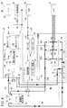
図1に示すように、本実施の形態に係るモータ駆動回路10は、バッテリ12から供給される電力によりモータ14を駆動する回路であり、該モータ14を駆動する電圧より低電圧の補機16についても、バッテリ12から電力を供給する。バッテリ12は、例えばリチウム・イオン型の二次電池である。なお、図1では電力線を太線、信号線を細線で区別して示している。
As shown in FIG. 1, a
モータ14は車両駆動用であり、図示しないタイヤを駆動する。車両のブレーキ時又は減速時には、モータ14は発電機として回生作用を奏し、バッテリ12に対して充電をすることができる。このように、モータ14は発電機としての機能も有しているが、便宜上モータと呼ぶ。バッテリ12は、例えば電圧が36V仕様であり、モータ14は36V駆動の仕様である。バッテリ12は、余裕をもって37V程度の充放電が可能である。モータ14は余裕をもって37V程度での駆動が可能である。
The motor 14 is for driving a vehicle and drives a tire (not shown). When the vehicle is braked or decelerated, the motor 14 acts as a generator and can recharge the
モータ駆動回路10は、バッテリ12、モータ14、補機16、DC・DCコンバータ18、パワードライブユニット(ドライバ)20、コンタクタ22、スイッチング素子(スイッチング手段)24及び過電圧検出回路25とを有する。コンタクタ22は、電磁力により動作する機械的接点によりオン・オフ制御をする。コンタクタ22によれば、パワードライブユニット20とバッテリ12とを切り離すことができ、暗電流によるバッテリ12の容量低下を防止するとともに、メンテナンス性の向上を図ることができる。
The
補機16は、例えば12V仕様であり、メータ26、ECU28及び一般電装品30を含む。一般電装品30に対してはスイッチ32を介して電力線を接続している。メータ26は、スピードメータ、モータ14の回転数メータ、オドメータ等を含む。一般電装品30は、ライト、エアコンディショナ、オーディオ機器等を含む。スイッチ32は、低耐圧で小型の廉価品であり、リレー34を介してDC・DCコンバータ18のオン・オフを行うことができる。
The
補機16に対しては、バッテリ12からDC・DCコンバータ18を介して電圧を12V(又は余裕を持って13V程度)に降圧して電力を供給している。このモータ駆動回路10では、補機16の専用の低電圧バッテリは設けられておらず、高電圧のバッテリ12が兼用している。これにより、レイアウトスペースの有効利用、配線の容易さ、軽量化及びコスト低減を図ることができる。
The
補機16の各グランド線は、DC・DCコンバータ18に接続され、該DC・DCコンバータ18内でグランドライン18nと接続している。
Each ground line of the
DC・DCコンバータ18は、スイッチ32によって開閉してオン・オフ制御するリレー34と、該リレー34から供給される電圧を12Vに降圧して補機16に供給する降圧コンバータ36と、12V電圧を36V(又は37V程度)に昇圧してパワードライブユニット20に供給する昇圧コンバータ38と、降圧コンバータ36の入力電圧を検出する電圧検出回路40とを有する。昇圧コンバータ38は、例えば図示しないキックスタータに対応しており、該キックスタータによって発生する電圧を昇圧してECU28等が安定して動作できる電圧を得ることができる。キックスタータによれば、例えばバッテリ12の電圧が低い場合にも車両の始動が可能になる。
The DC /
電圧検出回路40は、スイッチ32がオフの状態でクランク軸が回されたときに、モータ14が非制御状態で発電した電力を検出し、DC・DCコンバータ18から出力をしてECU28及びパワードライブユニット20を起動し、モータ14の発電制御を行うために設けられている。
The
リレー34と降圧コンバータ36との間には順方向のダイオード42が設けられ、電圧検出回路40と降圧コンバータ36の入力ラインとの間にはダイオード44が設けられている。
A
バッテリ12はプラス端子(第1極)12pと、マイナス端子(第2極)12nとを有する。プラス端子12pは、DC・DCコンバータ18のプラスライン18pに対してプラス電力線P1で接続されるとともに、パワードライブユニット20のプラスライン20pに対してプラス電力線(第1電源ライン)P2によりコンタクタ22を介して接続されている。プラス電力線P1及びP2は、それぞれ独立的にプラス端子12pに接続されていてもよいし、プラス端子12pに対する接続線を共通として途中で分岐していてもよい。
The
バッテリ12のマイナス端子12nとパワードライブユニット20はマイナス電力線(第2電源ライン)N1で接続されている。マイナス電力線N1は、パワードライブユニット20内で、スイッチング素子24を介してグランドライン(第2極ライン)20nと接続されている。
The
パワードライブユニット20のグランドライン20nとDC・DCコンバータ18のグランドライン(第2極ライン)18nは、接続ラインN2で接続されている。
The
パワードライブユニット20は、制御回路50と、降圧コンバータ52と、昇圧コンバータ54と、プリドライブ回路56と、インバータ回路58とを有する。
The
降圧コンバータ52は、補機16に供給される12V系統の電力線を入力とし、12Vの電圧(又は13V程度の電圧)を5Vに降圧して制御回路50に供給する。制御回路50はECU28と通信線59により接続されており、双方向の通信(例えば、CAN通信)を行う。制御回路50は供給される5V電圧を電力として動作し、ECU28から得られる情報に基づき、コンタクタ22開閉制御及びプリドライブ回路56の制御をする。制御回路50と過電圧検出回路25は信号線により接続され、情報交換が可能である。
The step-
昇圧コンバータ54は、補機16に供給される12V系統の電力線を入力とし、12Vの電圧(又は13V程度の電圧)を15Vに昇圧してプリドライブ回路56に供給する。プリドライブ回路56は、供給される15V電圧を電力として動作し、インバータ回路58の制御をする。
The step-up
インバータ回路58は、プラスライン20pとグランドライン20nとの間に直列接続された3組のスイッチング素子対60a、60b及び60cを有する。各スイッチング素子対60a〜60cは、上アーム62と下アーム64との直列接続構成であり、それぞれの接続ラインが三相出力となってモータ14に接続されている。上アーム62及び下アーム64は、それぞれ半導体素子であり、ゲートが個別にプリドライブ回路56に接続されている。プリドライブ回路56では、これらのゲートを制御して、プラスライン20pとグランドライン20nとの間の直流電圧を所望の周波数の三相交流に変換してモータ14に供給し、又はモータ14で発電した電力を直流に変換してバッテリ12に回生、充電をする。
The
インバータ回路58には、該回路内の過電圧を検出して制御回路50に検出結果を供給するドライバ過電圧検出回路61が設けられている。
The
スイッチング素子24は、例えばMOS−FETであり、ゲート70が過電圧検出回路25に接続され、ドレイン72がマイナス電力線N1に接続され、ソース74がグランドライン20nに接続されている。過電圧検出回路25はバッテリ12の電圧を監視し、過電圧を検出したときにはスイッチング素子24のゲートを制御し、該スイッチング素子24をオフにする。過電圧検出回路25に替え、又は併存させてバッテリ12の温度を検出してスイッチング素子24の制御をする手段を設けてもよい。
The switching
スイッチング素子24は、寄生ダイオードとしてのダイオード76が並列に設けられており、バッテリ12の放電方向(図1におけるマイナス電力線N1で右から左へ向かう方向)の電流を許容する向きに設定されている。つまり、ダイオード76のカソード側はマイナス電力線N1に接続され、アノード側はグランドライン20nに接続されている。スイッチング素子24に対して並列接続するダイオード76は、内蔵、外付け及びそれらの併存のいずれでもよい。
The switching
スイッチング素子24は、インバータ回路58内に設けられており、スイッチング素子24は、インバータ回路58の基板上に実装されており、スイッチング素子24専用の基板を設ける必要がない。
The switching
また、図2に示すように、スイッチング素子24は、各スイッチング素子対60a〜60cとともに共通の放熱板(放熱手段)78に取り付けられている。これにより、スイッチング素子24専用の放熱板を設ける必要がなく、省スペース、簡便構成となる。スイッチング素子24及びスイッチング素子対60a〜60cの放熱手段は放熱板78に限らず、例えば冷却水が流れる冷却管路、又は放熱板と冷却管路の複合体であってもよい。スイッチング素子24及びスイッチング素子対60a〜60cは、MOS−FET以外にも、IGBTやトランジスタ等の半導体素子であってもよい。半導体素子は、制御性、耐久性、実装容易性に優れており、モータ駆動回路10にけるスイッチング手段に好適である。
As shown in FIG. 2, the switching
次に、このように構成されるモータ駆動回路10の作用について説明する。
Next, the operation of the
図3に示すように、車両の通常運転時には、コンタクタ22は制御回路50によってオンに保持され、スイッチング素子24は過電圧検出回路25によってオンに保持される。これにより、バッテリ12から36Vの電圧がパワードライブユニット20に供給されて、インバータ回路58によって直流から三相交流に変換されてモータ14を駆動することができる。なお、図3、図4及び図5では、電源線において説明上の主要な線に太線で示すとともに電流の流れる向きを併記し、電流の流れない主要な線を破線で示してる。
As shown in FIG. 3, during normal operation of the vehicle, the
一方、補機16に対しては、バッテリ12からDC・DCコンバータ18で電圧を降圧して供給する。補機16の各グランド線はDC・DCコンバータ18の降圧コンバータ36及び昇圧コンバータ38内でグランドライン18nに接続されているが補機16の消費分は、結果としてプラス電力線P1及びプラスライン18pを流れるDC・DCコンバータ18の消費電流としてグランドライン18n及び接続ラインN2を介して、スイッチング素子24及びマイナス電力線N1を通りマイナス端子12nに流れ込む。
On the other hand, a voltage is stepped down from the
次に、図4に示すように、ブレーキ時又は減速時にモータ14が発電機として作用するときには、3組のスイッチング素子対60a、60b及び60cが制御回路50及びプリドライブ回路56によって適切にオン・オフ制御され、モータ14から供給される三相の電力は直流に変換されてプラスライン20p、コンタクタ22及びプラス電力線P2を介してプラス端子12pに流れ込み、バッテリ12が充電できる。このとき、マイナス端子12nからは電流が流れ出し、マイナス電力線N1、スイッチング素子24及びグランドライン20nを介してモータ14に流れ込んでいる。
Next, as shown in FIG. 4, when the motor 14 acts as a generator during braking or deceleration, the three switching
一方、補機16の消費分は結果としてDC・DCコンバータ18の消費電流として接続ラインN2を介してスイッチング素子24〜マイナス電力線N1〜マイナス端子12nに流れ込む。したがって、マイナス電力線N1では、補機16から流れ込む順方向電流と、モータ14に向かって流れ出す逆方向電流との差に応じた電流が流れることになる。
On the other hand, the consumption of the
図5に示すように、バッテリ12には充電の限界があり、過度に充電をすると過電圧となるため、過電圧検出回路25による検出をして、スイッチング素子24をオフにし、その後コンタクタ22をオフにする。コンタクタ22をオフにする以前にスイッチング素子24をオフにすることによりコンタクタ22には電流が流れなくなっているので、該コンタクタ22をオフにしてもアークの発生がない。
As shown in FIG. 5, the
この場合、インバータ回路58は停止することになるが、DC・DCコンバータ18及び補機16は有効となっている。すなわち、バッテリ12から供給される電力は、DC・DCコンバータ18で降圧されて各補機16へ分配され、各補機16の消費分はDC−DCコンバータ18の消費電流としてグランドライン20nに流れる。ここで、スイッチング素子24はオフだがダイオード76を通ってマイナス端子12nに流れ込む。
In this case, the
このようにして、バッテリ12が過電圧となって、スイッチング素子24をオフとしてインバータ回路58を停止させた場合であっても、補機16は継続的に稼動することができる。このとき、パワードライブユニット20の制御回路50及びプリドライブ回路56についても、12V系から降圧コンバータ52及び昇圧コンバータ54を介して電力が供給されるため有効であることはもちろんである。
In this way, even when the
なお、モータ駆動回路10の起動時には、先ずコンタクタ22をオンにし、微小時間後にスイッチング素子24をオンにし、モータ駆動回路10の終了時には、先ずスイッチング素子24をオフにして、微小時間後にコンタクタ22をオフにするとよい。つまり、コンタクタ22のオン、オフ時にはスイッチング素子24をオフにしておき、コンタクタ22に電圧が印加されていない状態とすることで、該コンタクタ22にアークが発生することを防止できる。もちろん、コンタクタ22が大型で大電流を遮断可能であればよいのだが、コスト及びスペース利用の観点からは小型であることが望ましい。したがって、上記の通りスイッチング素子24を併用することによってコンタクタ22を小型化することができる。
When the
スイッチング素子24及びコンタクタ22をオフにするのは、バッテリ12が過電圧になった場合だけでなく、インバータ回路58内で過電圧が発生した場合においても、ドライバ過電圧検出回路61にて検出し、制御回路50、過電圧検出回路25を介してスイッチング素子24をオフにするとともに、コンタクタ22をオフにしてもよい。
The switching
上述したように、本実施の形態に係るモータ駆動回路10によれば、接続ラインN2とバッテリ12のマイナス端子12nとを接続するマイナス電力線N1にスイッチング素子24を設けることにより、インバータ回路58をバッテリ12から確実に切り離すことができ、切り離しをするコンタクタ22においてアークの発生を抑制することができる。
As described above, according to the
また、スイッチング素子24には並列にダイオード76が設けられており、スイッチング素子24によりインバータ回路58を切り離した後にもバッテリ12から補機16に対して電力供給を継続することができる。
In addition, the switching
スイッチング素子24は、過電圧検出回路25及びドライバ過電圧検出回路61によってスイッチング制御され、バッテリ12及びインバータ回路58に対しする過電圧の発生を防止できる。
The switching
このようなモータ駆動回路10は、ハイブリッド車両等にも適用可能であることはもちろんである。モータ駆動回路10をハイブリッド車両に適用する場合には、モータ14は、独立的な走行駆動源として作用する他に、エンジンアシスト、エンジン始動等の作用を奏する。モータ駆動回路10を自動二輪車のハイブリッド車に適用する場合には、モータ14をクランク軸の左に取り付けるとよい。ハイブリッド車両の場合には、キックスタータを併用してもよい。
Of course, such a
モータ駆動回路10をハイブリッド車両に適用した場合におけるシステム始動時の制御手順について図6を参照しながら説明する。
A control procedure at the time of starting the system when the
ステップS1において、スイッチ32をオンすることによりシステムが起動する。
In step S1, the system is started by turning on the
ステップS2において、バッテリ12の状態を確認し、該バッテリ12が過放電となっていないか確認する。過放電である場合にはステップS15へ移り、そうでない場合にはステップS3へ移る。
In step S2, the state of the
ステップS3において、DC・DCコンバータ18内のリレー34をオンにする。
In step S3, the
ステップS4において、降圧コンバータ36が出力を開始する。
In step S4, the step-
ステップS5において、ECU28、パワードライブユニット20等が起動する。
In step S5, the
ステップS6において、所定のシステムチェックを行う。 In step S6, a predetermined system check is performed.
ステップS7において、システムチェックの結果によりフェイルが検出されたときにはステップS8において所定のワーニング表示を行い、起動処理を中断し、フェイルがないときにはステップS9へ移る。ワーニング表示は、例えばメータ26に表示する。
In step S7, when a failure is detected as a result of the system check, a predetermined warning is displayed in step S8, the activation process is interrupted, and if there is no failure, the process proceeds to step S9. The warning display is displayed on the
ステップS9において、コンタクタ22及びスイッチング素子24をオンにする。
In step S9, the
ステップS10において、所定のスタータスイッチを確認し、該スタータスイッチがオンになればステップS12へ移り、オフであるときにはステップS11へ移る。 In step S10, a predetermined starter switch is confirmed. If the starter switch is turned on, the process proceeds to step S12. If the starter switch is turned off, the process proceeds to step S11.
ステップS11において、キックスタータによる始動が行われたか確認する。キックスタータによる始動が行われた場合にはステップS13へ移り、それ以外の場合にはステップS10へ戻る。 In step S11, it is confirmed whether the kick starter has been started. When the start by the kick starter is performed, the process proceeds to step S13, and otherwise, the process returns to step S10.
ステップS12において、モータ14の駆動を開始する。 In step S12, driving of the motor 14 is started.
ステップS13において、エンジンの点火制御を開始する。 In step S13, engine ignition control is started.
この後、ステップS14において所定の走行制御に移行する。 Thereafter, the process proceeds to predetermined traveling control in step S14.
一方、ステップS15においては、キックスタータによる始動が行われたか確認する。キックスタータによる始動が行われた場合にはステップS16へ移り、それ以外の場合には待機する。 On the other hand, in step S15, it is confirmed whether the start by the kick starter has been performed. When the start by the kick starter has been performed, the process proceeds to step S16, and in other cases, the process waits.
ステップS16において、昇圧コンバータ38が出力を開始する。
In step S16,
ステップS17において、ECU28、パワードライブユニット20等が起動する。
In step S17, the
ステップS18において、所定のシステムチェックを行う。 In step S18, a predetermined system check is performed.
ステップS19において、システムチェックの結果によりフェイルが検出されたときにはステップS20において所定のワーニング表示を行い、起動処理を中断し、フェイルがないときにはステップS21へ移る。 In step S19, when a failure is detected as a result of the system check, a predetermined warning display is performed in step S20, the activation process is interrupted, and if there is no failure, the process proceeds to step S21.
ステップS21において、エンジンの点火制御を開始する。 In step S21, engine ignition control is started.
ステップS22において、コンタクタ22及びスイッチング素子24をオンにする。この後、ステップS14へ移る。
In step S22, the
本発明に係るモータ駆動回路は、上述の実施の形態に限らず、本発明の要旨を逸脱することなく、種々の構成を採り得ることはもちろんである。 The motor drive circuit according to the present invention is not limited to the above-described embodiment, and various configurations can be adopted without departing from the gist of the present invention.
10…モータ駆動回路 12…バッテリ
12n…マイナス端子(第2極) 12p…プラス端子(第1極)
14…モータ 16…補機
18…コンバータ 18n、20n…グランドライン
18p、20p…プラスライン 20…パワードライブユニット
22…コンタクタ 24…スイッチング素子
25…過電圧検出回路 26…メータ
28…ECU 30…一般電装品
36、52…降圧コンバータ 38、54…昇圧コンバータ
50…制御回路 56…プリドライブ回路
58…インバータ回路 61…ドライバ過電圧検出回路
76…ダイオード 78…放熱板
P1、P2…プラス電力線(第1電源ライン)
N1…マイナス電力線N1(第2電源ライン)
N2…接続ライン
DESCRIPTION OF
DESCRIPTION OF SYMBOLS 14 ...
N1... Negative power line N1 (second power supply line)
N2 ... Connection line
Claims (1)
前記バッテリ(12)から供給される電圧を降圧して前記補機(16)に供給するDC・DCコンバータ(18)と、
前記バッテリ(12)から供給される電力を制御して前記モータ(14)を駆動するとともに、前記モータ(14)の回転で発生する電力を前記バッテリ(12)に回生するドライバ(20)と、
前記バッテリ(12)の前記第1極(12p)と前記ドライバ(20)の第1極ライン(20p)とを接続する第1電源ライン(P2)に設けられた機械的接点を備えるコンタクタ(22)と、
前記DC・DCコンバータ(18)の第2極ライン(18n)と前記ドライバ(20)の第2極ライン(20n)とを接続する接続ライン(N2)と、
前記接続ライン(N2)と前記バッテリ(12)の前記第2極(12n)とを接続する第2電源ライン(N1)に設けられた半導体素子であるスイッチング手段(24)と、
前記スイッチング手段(24)に対して並列で、前記バッテリ(12)の放電方向の電流を許容する向きに設けられたダイオード(76)と、
前記バッテリ(12)及び前記ドライバ(20)の過電圧を検出する過電圧検出手段(25、61)と、
を有し、
前記半導体素子は、前記ドライバ(20)の基板上に実装され、且つ、前記モータ(14)に電流を供給するインバータ回路(58)の半導体素子と共通の放熱手段に取り付けられており、
前記コンタクタ(22)をオンオフするときには、先に前記スイッチング手段(24)をオフにし、
前記スイッチング手段(24)は、過電圧が検出されると前記過電圧検出手段(25、61)によってスイッチング制御される
ことを特徴とするモータ駆動回路(10)。 Electric power is supplied from a battery (12) having a first pole (12p) and a second pole (12n) to a motor (14) and an auxiliary machine (16) having a lower voltage than a voltage for driving the motor (14). A motor drive circuit (10),
A DC / DC converter (18) that steps down the voltage supplied from the battery (12) and supplies the voltage to the auxiliary machine (16);
A driver (20) for controlling the power supplied from the battery (12) to drive the motor (14) and regenerating the power generated by the rotation of the motor (14) to the battery (12);
Contactor (22) provided with a mechanical contact provided on a first power supply line (P2) connecting the first pole (12p) of the battery (12) and the first pole line (20p) of the driver (20). )When,
A connection line (N2) connecting the second pole line (18n) of the DC / DC converter (18) and the second pole line (20n) of the driver (20);
Switching means (24) which is a semiconductor element provided in a second power supply line (N1) for connecting the connection line (N2) and the second pole (12n) of the battery (12);
A diode (76) provided in parallel with the switching means (24) and in a direction allowing a current in a discharging direction of the battery (12);
Overvoltage detection means (25, 61) for detecting overvoltage of the battery (12) and the driver (20);
Have
The semiconductor element is mounted on a substrate of the driver (20) and attached to a heat dissipating means common to the semiconductor element of the inverter circuit (58) for supplying current to the motor (14).
When turning on or off the contactor (22), the switching means (24) is turned off first ,
The motor drive circuit (10), wherein the switching means (24) is switching-controlled by the overvoltage detection means (25, 61) when an overvoltage is detected .
Priority Applications (1)
| Application Number | Priority Date | Filing Date | Title |
|---|---|---|---|
| JP2007336361A JP5160882B2 (en) | 2007-12-27 | 2007-12-27 | Motor drive circuit |
Applications Claiming Priority (1)
| Application Number | Priority Date | Filing Date | Title |
|---|---|---|---|
| JP2007336361A JP5160882B2 (en) | 2007-12-27 | 2007-12-27 | Motor drive circuit |
Publications (3)
| Publication Number | Publication Date |
|---|---|
| JP2009159755A JP2009159755A (en) | 2009-07-16 |
| JP2009159755A5 JP2009159755A5 (en) | 2010-08-19 |
| JP5160882B2 true JP5160882B2 (en) | 2013-03-13 |
Family
ID=40963148
Family Applications (1)
| Application Number | Title | Priority Date | Filing Date |
|---|---|---|---|
| JP2007336361A Active JP5160882B2 (en) | 2007-12-27 | 2007-12-27 | Motor drive circuit |
Country Status (1)
| Country | Link |
|---|---|
| JP (1) | JP5160882B2 (en) |
Families Citing this family (5)
| Publication number | Priority date | Publication date | Assignee | Title |
|---|---|---|---|---|
| JP2011078272A (en) * | 2009-10-01 | 2011-04-14 | Mitsubishi Electric Corp | Power supply device for in-vehicle equipment |
| KR101360820B1 (en) | 2009-12-21 | 2014-02-10 | 에스케이이노베이션 주식회사 | Hybrid protection circuit in hybrid vehicle |
| JP2013176241A (en) * | 2012-02-27 | 2013-09-05 | Auto Network Gijutsu Kenkyusho:Kk | Circuit unit |
| CN107709080B (en) | 2015-04-27 | 2020-10-27 | 松下知识产权经营株式会社 | Battery management device and power supply system |
| JP6724455B2 (en) * | 2016-03-22 | 2020-07-15 | トヨタ自動車株式会社 | Vehicle power supply system |
Family Cites Families (4)
| Publication number | Priority date | Publication date | Assignee | Title |
|---|---|---|---|---|
| JPH06276608A (en) * | 1993-03-19 | 1994-09-30 | Fuji Electric Co Ltd | Electric system for electric motor vehicle |
| JPH11134992A (en) * | 1997-10-28 | 1999-05-21 | Ando Electric Co Ltd | Relay switching circuit |
| JP2006015887A (en) * | 2004-07-02 | 2006-01-19 | Sanyo Electric Co Ltd | Motor-assisted bicycle |
| JP4519728B2 (en) * | 2005-07-15 | 2010-08-04 | 本田技研工業株式会社 | Control device for electric vehicle |
-
2007
- 2007-12-27 JP JP2007336361A patent/JP5160882B2/en active Active
Also Published As
| Publication number | Publication date |
|---|---|
| JP2009159755A (en) | 2009-07-16 |
Similar Documents
| Publication | Publication Date | Title |
|---|---|---|
| JP4735000B2 (en) | Motor drive device | |
| US8508066B2 (en) | Emergency control apparatus and method for use | |
| JP5648211B2 (en) | Plug-in hybrid vehicle charging device | |
| JP4701821B2 (en) | Load driving device and vehicle equipped with the same | |
| US9843184B2 (en) | Voltage conversion apparatus | |
| JP6469424B2 (en) | Vehicle power supply | |
| JP2012125137A (en) | High voltage system of electric vehicle | |
| KR20110054513A (en) | Mild hybrid system and method controlling thereof | |
| JP2008149897A (en) | Control device for power supply circuit | |
| CN105006852A (en) | Power supply | |
| JP2014131404A (en) | Vehicle charger | |
| JP2009290920A (en) | Power supply controller for electric vehicle | |
| JP2006304390A (en) | Power unit for hybrid vehicle | |
| JP5160882B2 (en) | Motor drive circuit | |
| JP2019006263A (en) | Vehicle control apparatus | |
| JP2016187236A (en) | Battery system control device | |
| JP2015180140A (en) | Power supply system for vehicle | |
| JP6651605B2 (en) | Control device for hybrid vehicle | |
| JP2011147237A (en) | Apparatus for control of regenerative charge for electric vehicles | |
| JP2007089264A (en) | Motor driver | |
| JP6673046B2 (en) | Power supply system for electric vehicles | |
| KR101836643B1 (en) | Mild hybrid system of vehicle | |
| JP2015523257A (en) | Transient polarity control with insulated contactors | |
| JP2013150525A (en) | Electric vehicle | |
| JP5808707B2 (en) | Electric car |
Legal Events
| Date | Code | Title | Description |
|---|---|---|---|
| A521 | Written amendment |
Free format text: JAPANESE INTERMEDIATE CODE: A523 Effective date: 20100702 |
|
| A621 | Written request for application examination |
Free format text: JAPANESE INTERMEDIATE CODE: A621 Effective date: 20100702 |
|
| A977 | Report on retrieval |
Free format text: JAPANESE INTERMEDIATE CODE: A971007 Effective date: 20110829 |
|
| A131 | Notification of reasons for refusal |
Free format text: JAPANESE INTERMEDIATE CODE: A131 Effective date: 20110906 |
|
| A521 | Written amendment |
Free format text: JAPANESE INTERMEDIATE CODE: A523 Effective date: 20111102 |
|
| A131 | Notification of reasons for refusal |
Free format text: JAPANESE INTERMEDIATE CODE: A131 Effective date: 20120605 |
|
| A521 | Written amendment |
Free format text: JAPANESE INTERMEDIATE CODE: A523 Effective date: 20120713 |
|
| TRDD | Decision of grant or rejection written | ||
| A01 | Written decision to grant a patent or to grant a registration (utility model) |
Free format text: JAPANESE INTERMEDIATE CODE: A01 Effective date: 20121204 |
|
| A61 | First payment of annual fees (during grant procedure) |
Free format text: JAPANESE INTERMEDIATE CODE: A61 Effective date: 20121213 |
|
| R150 | Certificate of patent or registration of utility model |
Ref document number: 5160882 Country of ref document: JP Free format text: JAPANESE INTERMEDIATE CODE: R150 Free format text: JAPANESE INTERMEDIATE CODE: R150 |
|
| FPAY | Renewal fee payment (event date is renewal date of database) |
Free format text: PAYMENT UNTIL: 20151221 Year of fee payment: 3 |
|
| R250 | Receipt of annual fees |
Free format text: JAPANESE INTERMEDIATE CODE: R250 |