EP1612029A1 - Method and device for forming composite synthetic resin material - Google Patents
Method and device for forming composite synthetic resin material Download PDFInfo
- Publication number
- EP1612029A1 EP1612029A1 EP04704327A EP04704327A EP1612029A1 EP 1612029 A1 EP1612029 A1 EP 1612029A1 EP 04704327 A EP04704327 A EP 04704327A EP 04704327 A EP04704327 A EP 04704327A EP 1612029 A1 EP1612029 A1 EP 1612029A1
- Authority
- EP
- European Patent Office
- Prior art keywords
- synthetic resin
- channel
- outermost
- outlet
- opening
- Prior art date
- Legal status (The legal status is an assumption and is not a legal conclusion. Google has not performed a legal analysis and makes no representation as to the accuracy of the status listed.)
- Granted
Links
Images



Classifications
-
- B—PERFORMING OPERATIONS; TRANSPORTING
- B29—WORKING OF PLASTICS; WORKING OF SUBSTANCES IN A PLASTIC STATE IN GENERAL
- B29B—PREPARATION OR PRETREATMENT OF THE MATERIAL TO BE SHAPED; MAKING GRANULES OR PREFORMS; RECOVERY OF PLASTICS OR OTHER CONSTITUENTS OF WASTE MATERIAL CONTAINING PLASTICS
- B29B11/00—Making preforms
- B29B11/06—Making preforms by moulding the material
- B29B11/10—Extrusion moulding
-
- B—PERFORMING OPERATIONS; TRANSPORTING
- B29—WORKING OF PLASTICS; WORKING OF SUBSTANCES IN A PLASTIC STATE IN GENERAL
- B29C—SHAPING OR JOINING OF PLASTICS; SHAPING OF MATERIAL IN A PLASTIC STATE, NOT OTHERWISE PROVIDED FOR; AFTER-TREATMENT OF THE SHAPED PRODUCTS, e.g. REPAIRING
- B29C48/00—Extrusion moulding, i.e. expressing the moulding material through a die or nozzle which imparts the desired form; Apparatus therefor
- B29C48/25—Component parts, details or accessories; Auxiliary operations
- B29C48/285—Feeding the extrusion material to the extruder
-
- B—PERFORMING OPERATIONS; TRANSPORTING
- B29—WORKING OF PLASTICS; WORKING OF SUBSTANCES IN A PLASTIC STATE IN GENERAL
- B29C—SHAPING OR JOINING OF PLASTICS; SHAPING OF MATERIAL IN A PLASTIC STATE, NOT OTHERWISE PROVIDED FOR; AFTER-TREATMENT OF THE SHAPED PRODUCTS, e.g. REPAIRING
- B29C48/00—Extrusion moulding, i.e. expressing the moulding material through a die or nozzle which imparts the desired form; Apparatus therefor
- B29C48/001—Combinations of extrusion moulding with other shaping operations
- B29C48/0017—Combinations of extrusion moulding with other shaping operations combined with blow-moulding or thermoforming
-
- B—PERFORMING OPERATIONS; TRANSPORTING
- B29—WORKING OF PLASTICS; WORKING OF SUBSTANCES IN A PLASTIC STATE IN GENERAL
- B29C—SHAPING OR JOINING OF PLASTICS; SHAPING OF MATERIAL IN A PLASTIC STATE, NOT OTHERWISE PROVIDED FOR; AFTER-TREATMENT OF THE SHAPED PRODUCTS, e.g. REPAIRING
- B29C48/00—Extrusion moulding, i.e. expressing the moulding material through a die or nozzle which imparts the desired form; Apparatus therefor
- B29C48/03—Extrusion moulding, i.e. expressing the moulding material through a die or nozzle which imparts the desired form; Apparatus therefor characterised by the shape of the extruded material at extrusion
- B29C48/09—Articles with cross-sections having partially or fully enclosed cavities, e.g. pipes or channels
-
- B—PERFORMING OPERATIONS; TRANSPORTING
- B29—WORKING OF PLASTICS; WORKING OF SUBSTANCES IN A PLASTIC STATE IN GENERAL
- B29C—SHAPING OR JOINING OF PLASTICS; SHAPING OF MATERIAL IN A PLASTIC STATE, NOT OTHERWISE PROVIDED FOR; AFTER-TREATMENT OF THE SHAPED PRODUCTS, e.g. REPAIRING
- B29C48/00—Extrusion moulding, i.e. expressing the moulding material through a die or nozzle which imparts the desired form; Apparatus therefor
- B29C48/03—Extrusion moulding, i.e. expressing the moulding material through a die or nozzle which imparts the desired form; Apparatus therefor characterised by the shape of the extruded material at extrusion
- B29C48/09—Articles with cross-sections having partially or fully enclosed cavities, e.g. pipes or channels
- B29C48/10—Articles with cross-sections having partially or fully enclosed cavities, e.g. pipes or channels flexible, e.g. blown foils
-
- B—PERFORMING OPERATIONS; TRANSPORTING
- B29—WORKING OF PLASTICS; WORKING OF SUBSTANCES IN A PLASTIC STATE IN GENERAL
- B29C—SHAPING OR JOINING OF PLASTICS; SHAPING OF MATERIAL IN A PLASTIC STATE, NOT OTHERWISE PROVIDED FOR; AFTER-TREATMENT OF THE SHAPED PRODUCTS, e.g. REPAIRING
- B29C48/00—Extrusion moulding, i.e. expressing the moulding material through a die or nozzle which imparts the desired form; Apparatus therefor
- B29C48/16—Articles comprising two or more components, e.g. co-extruded layers
-
- B—PERFORMING OPERATIONS; TRANSPORTING
- B29—WORKING OF PLASTICS; WORKING OF SUBSTANCES IN A PLASTIC STATE IN GENERAL
- B29C—SHAPING OR JOINING OF PLASTICS; SHAPING OF MATERIAL IN A PLASTIC STATE, NOT OTHERWISE PROVIDED FOR; AFTER-TREATMENT OF THE SHAPED PRODUCTS, e.g. REPAIRING
- B29C48/00—Extrusion moulding, i.e. expressing the moulding material through a die or nozzle which imparts the desired form; Apparatus therefor
- B29C48/16—Articles comprising two or more components, e.g. co-extruded layers
- B29C48/18—Articles comprising two or more components, e.g. co-extruded layers the components being layers
- B29C48/19—Articles comprising two or more components, e.g. co-extruded layers the components being layers the layers being joined at their edges
-
- B—PERFORMING OPERATIONS; TRANSPORTING
- B29—WORKING OF PLASTICS; WORKING OF SUBSTANCES IN A PLASTIC STATE IN GENERAL
- B29C—SHAPING OR JOINING OF PLASTICS; SHAPING OF MATERIAL IN A PLASTIC STATE, NOT OTHERWISE PROVIDED FOR; AFTER-TREATMENT OF THE SHAPED PRODUCTS, e.g. REPAIRING
- B29C48/00—Extrusion moulding, i.e. expressing the moulding material through a die or nozzle which imparts the desired form; Apparatus therefor
- B29C48/16—Articles comprising two or more components, e.g. co-extruded layers
- B29C48/18—Articles comprising two or more components, e.g. co-extruded layers the components being layers
- B29C48/21—Articles comprising two or more components, e.g. co-extruded layers the components being layers the layers being joined at their surfaces
-
- B—PERFORMING OPERATIONS; TRANSPORTING
- B29—WORKING OF PLASTICS; WORKING OF SUBSTANCES IN A PLASTIC STATE IN GENERAL
- B29C—SHAPING OR JOINING OF PLASTICS; SHAPING OF MATERIAL IN A PLASTIC STATE, NOT OTHERWISE PROVIDED FOR; AFTER-TREATMENT OF THE SHAPED PRODUCTS, e.g. REPAIRING
- B29C48/00—Extrusion moulding, i.e. expressing the moulding material through a die or nozzle which imparts the desired form; Apparatus therefor
- B29C48/25—Component parts, details or accessories; Auxiliary operations
- B29C48/30—Extrusion nozzles or dies
- B29C48/304—Extrusion nozzles or dies specially adapted for bringing together components, e.g. melts within the die
-
- B—PERFORMING OPERATIONS; TRANSPORTING
- B29—WORKING OF PLASTICS; WORKING OF SUBSTANCES IN A PLASTIC STATE IN GENERAL
- B29C—SHAPING OR JOINING OF PLASTICS; SHAPING OF MATERIAL IN A PLASTIC STATE, NOT OTHERWISE PROVIDED FOR; AFTER-TREATMENT OF THE SHAPED PRODUCTS, e.g. REPAIRING
- B29C48/00—Extrusion moulding, i.e. expressing the moulding material through a die or nozzle which imparts the desired form; Apparatus therefor
- B29C48/25—Component parts, details or accessories; Auxiliary operations
- B29C48/30—Extrusion nozzles or dies
- B29C48/32—Extrusion nozzles or dies with annular openings, e.g. for forming tubular articles
- B29C48/335—Multiple annular extrusion nozzles in coaxial arrangement, e.g. for making multi-layered tubular articles
- B29C48/336—Multiple annular extrusion nozzles in coaxial arrangement, e.g. for making multi-layered tubular articles the components merging one by one down streams in the die
- B29C48/3366—Multiple annular extrusion nozzles in coaxial arrangement, e.g. for making multi-layered tubular articles the components merging one by one down streams in the die using a die with concentric parts, e.g. rings, cylinders
-
- B—PERFORMING OPERATIONS; TRANSPORTING
- B29—WORKING OF PLASTICS; WORKING OF SUBSTANCES IN A PLASTIC STATE IN GENERAL
- B29C—SHAPING OR JOINING OF PLASTICS; SHAPING OF MATERIAL IN A PLASTIC STATE, NOT OTHERWISE PROVIDED FOR; AFTER-TREATMENT OF THE SHAPED PRODUCTS, e.g. REPAIRING
- B29C48/00—Extrusion moulding, i.e. expressing the moulding material through a die or nozzle which imparts the desired form; Apparatus therefor
- B29C48/25—Component parts, details or accessories; Auxiliary operations
- B29C48/36—Means for plasticising or homogenising the moulding material or forcing it through the nozzle or die
- B29C48/375—Plasticisers, homogenisers or feeders comprising two or more stages
- B29C48/387—Plasticisers, homogenisers or feeders comprising two or more stages using a screw extruder and a gear pump
-
- B—PERFORMING OPERATIONS; TRANSPORTING
- B29—WORKING OF PLASTICS; WORKING OF SUBSTANCES IN A PLASTIC STATE IN GENERAL
- B29C—SHAPING OR JOINING OF PLASTICS; SHAPING OF MATERIAL IN A PLASTIC STATE, NOT OTHERWISE PROVIDED FOR; AFTER-TREATMENT OF THE SHAPED PRODUCTS, e.g. REPAIRING
- B29C48/00—Extrusion moulding, i.e. expressing the moulding material through a die or nozzle which imparts the desired form; Apparatus therefor
- B29C48/25—Component parts, details or accessories; Auxiliary operations
- B29C48/36—Means for plasticising or homogenising the moulding material or forcing it through the nozzle or die
- B29C48/49—Means for plasticising or homogenising the moulding material or forcing it through the nozzle or die using two or more extruders to feed one die or nozzle
-
- B—PERFORMING OPERATIONS; TRANSPORTING
- B29—WORKING OF PLASTICS; WORKING OF SUBSTANCES IN A PLASTIC STATE IN GENERAL
- B29C—SHAPING OR JOINING OF PLASTICS; SHAPING OF MATERIAL IN A PLASTIC STATE, NOT OTHERWISE PROVIDED FOR; AFTER-TREATMENT OF THE SHAPED PRODUCTS, e.g. REPAIRING
- B29C49/00—Blow-moulding, i.e. blowing a preform or parison to a desired shape within a mould; Apparatus therefor
- B29C49/02—Combined blow-moulding and manufacture of the preform or the parison
- B29C49/04—Extrusion blow-moulding
- B29C49/04102—Extrusion blow-moulding extruding the material continuously
Definitions
- This invention relates to a composite synthetic resin material formation method and apparatus for forming a composite synthetic resin material including an outer synthetic resin layer, and at least one inner synthetic resin layer wrapped in the outer synthetic resin layer.
- a composite synthetic resin material including an outer synthetic resin layer, and at least one inner synthetic resin layer wrapped in the outer synthetic resin layer is often used as a synthetic resin material for forming a preforming product (generally called a preform) to be blow molded into a beverage container, or for forming a container closure.
- a synthetic resin excellent in mechanical properties and hygienic properties is selected as the outer synthetic resin, while a synthetic resin excellent in gas barrier properties is selected as the inner synthetic resin.
- Japanese Published Unexamined Patent Application No. Hei 1-195016 discloses a composite synthetic resin material forming apparatus comprising an outermost channel having an outermost outlet, an outer channel having an outer outlet opening into the outermost channel, an inner channel having an inner outlet opening into the outer channel, an outermost synthetic resin supply means for flowing an outermost synthetic resin through the outermost channel, an outer synthetic resin supply means for flowing an outer synthetic resin through the outer channel, and an inner synthetic resin supply means for flowing an inner synthetic resin through the inner channel.
- the inner outlet has an opening and closing means annexed thereto for selectively opening and closing the inner outlet. In accordance with the opening and closing of the inner outlet by the opening and closing means, the inner synthetic resin is intermittently flowed from the inner channel into the outermost channel via the outer channel.
- This inner synthetic resin is wrapped in the outermost synthetic resin directly flowed into the outermost channel, and the outer synthetic resin (the outer synthetic resin and the outermost synthetic resin may be the same synthetic resin) flowed into the outermost channel via the outer channel. As a result, a composite synthetic resin material is flowed out of the outermost outlet.
- Japanese Published Unexamined Patent Application No. Hei 6-15715 also discloses a composite synthetic resin material forming apparatus comprising an outermost channel having an outermost outlet, an outer channel having an outer outlet opening into the outermost channel, an inner channel having an inner outlet opening into the outer channel, an outermost synthetic resin supply means for flowing an outermost synthetic resin through the outermost channel, an outer synthetic resin supply means for flowing an outer synthetic resin through the outer channel, and an inner synthetic resin supply means for flowing an inner synthetic resin through the inner channel.
- the outermost synthetic resin supply means is continuously operated to continuously flow the outermost synthetic resin directly into the outermost channel.
- the inner synthetic resin supply means is intermittently operated to intermittently flow the inner synthetic resin into the outermost channel via the outer channel.
- the outer synthetic resin supply means is intermittently operated a required time behind the intermittent operation of the inner synthetic resin supply means to intermittently flow the outer synthetic resin (the outer synthetic resin and the outermost synthetic resin may be the same synthetic resin) into the outer channel.
- the composite synthetic resin material forming apparatus disclosed in the aforementioned Japanese Published Unexamined Patent Application No. Hei 1-195016 has the following problems to be solved: Particularly when the composite synthetic resin material is to be flowed out of the outermost outlet at a relatively high speed, the inner synthetic resin, which has been wrapped in the outermost synthetic resin and the outer synthetic resin, leaves a relatively long, thin trail in the flowing direction. Thus, the length, in the flowing direction, of a region where the inner synthetic resin is not present becomes markedly short.
- the outer synthetic resin is intermittently caused to inflow a predetermined time behind the intermittent inflow of the inner synthetic resin to pressurize the inner synthetic resin from the upstream side in the flowing direction, thereby shortening the length, in the flowing direction, of the inner synthetic resin so that the above problem with the composite synthetic resin material forming apparatus disclosed in the aforementioned Japanese Published Unexamined Patent Application No. Hei 1-195016 can be solved.
- the composite synthetic resin material forming apparatus disclosed in the above-described Japanese Published Unexamined Patent Application No. Hei 6-15715 is still not fully satisfactory.
- the inventors conducted in-depth studies, and have found that the above principal object can be attained by selectively opening and closing an inner outlet, and intermittently supplying an outer synthetic resin into an outer channel in accordance with the opening and closing of the inner outlet, in a composite synthetic resin material forming mode in which the outer synthetic resin is flowed through the outer channel having an outer outlet, and an inner synthetic resin is flowed through an inner channel having the inner outlet opening into the outer channel.
- a composite synthetic resin material forming method for attaining the above principal object a composite synthetic resin material forming method arranged to flow an outer synthetic resin through an outer channel having an outer outlet, and flow an inner synthetic resin through an inner channel having an inner outlet opening into the outer channel, the method comprising:
- the method includes flowing an outermost synthetic resin through an outermost channel having an outermost outlet, and the outer outlet preferably opens into the outermost channel.
- a composite synthetic resin material forming apparatus for attaining the above principal object, a composite synthetic resin material forming apparatus comprising:
- the outer synthetic resin supply means starts the supply of the outer synthetic resin simultaneously with or before the closing of the inner outlet by the opening and closing means, and stops the supply of the outer synthetic resin simultaneously with or before the opening of the inner outlet by the opening and closing means.
- the inner synthetic resin supply means is continuously operated.
- the composite synthetic resin material forming apparatus further comprises an outermost channel having an outermost outlet, and an outermost synthetic resin supply means for flowing an outermost synthetic resin through the outermost channel, and the outer outlet opens into the outermost channel.
- the outermost synthetic resin supply means may be operated continuously or intermittently.
- the outer synthetic resin supply means can be constructed of an extruder which is continuously operated, and a gear pump connected downwardly of the extruder and intermittently operated.
- the outer synthetic resin supply means can be constructed of an extruder which is continuously operated, two plunger means, and a switching means which is alternately set in a first state where the switching means brings one of the plunger means into communication with the extruder, and brings the other plunger means into communication with the outer channel, and a second state where the switching means brings the one of the plunger means into communication with the outer channel, and brings the other plunger means into communication with the extruder.
- the outer synthetic resin supply means can be constructed of an extruder which is continuously operated, and an intermittent communications means which intermittently brings the extruder into communication with the outer channel.
- a composite synthetic resin material to be formed may be compression molded into a preforming product (usually called a preform) which is, for example, blow molded later into a container.
- FIG. 1 shows a main portion of the composite synthetic resin material forming apparatus constructed in accordance with the present invention.
- This apparatus has a nozzle means 2, only a tip portion of which is shown.
- the nozzle means 2 which can be constructed by combining a plurality of members formable from a suitable metal, an outermost channel 4, an outer channel 6, and an inner channel 8 are formed.
- the outermost channel 4 includes an introduction portion 4a of an annular cross sectional shape, and a discharge portion 4b of a circular cross sectional shape.
- a downstream part of the introduction portion 4a extends toward a downstream side progressively obliquely in a radially inward direction, and the downstream end of the introduction portion 4a is connected to an upstream end peripheral edge portion of the discharge portion 4b.
- An outermost outlet 4c is formed at the downstream end of the discharge portion 4b.
- the outer channel 6 similarly includes an introduction portion 6a of an annular cross sectional shape, and a discharge portion 6b of a circular cross sectional shape.
- a downstream part of the introduction portion 6a extends toward a downstream side progressively obliquely in a radially inward direction, and the downstream end of the introduction portion 6a is connected to an upstream end peripheral edge portion of the discharge portion 6b.
- the discharge portion 6b is relatively short, and an outer outlet 6c is formed at the downstream end of the discharge portion 6b.
- the outer outlet 6c is open at the upper end center of the discharge portion 4b of the outermost channel 4.
- the inner channel 8 similarly includes an introduction portion 8a of an annular cross sectional shape, and a discharge portion 8b of a circular cross sectional shape.
- a downstream part of the introduction portion 8a extends toward a downstream side obliquely in a radially inward direction, and the downstream end of the introduction portion 8a is connected to the discharge portion 8b.
- the discharge portion 8b is relatively short, and an inner outlet 8c is formed at the downstream end of the discharge portion 8b.
- the inner outlet 8c is open at the upper end of the discharge portion 6b of the outer channel 6.
- the upstream end of the outermost channel 4 is connected to an outermost synthetic resin supply means 10 via a suitable communication passage (not shown).
- the outermost synthetic resin supply means 10 includes an extruder 12, and a gear pump 14 connected downstream of the extruder 12, whereby an outermost synthetic resin A (FIGS. 3(i) to 3(vi)) in a molten state extruded from the extruder 12 is supplied to the outermost channel 4 via the gear pump 14.
- the upstream end of the outer channel 6 is connected to an outer synthetic resin supply means 16 via a suitable communication passage (not shown).
- the outer synthetic resin supply means 16 includes an extruder 18, and a gear pump 20 connected downstream of the extruder 18, whereby an outer synthetic resin B (FIGS.
- the outermost synthetic resin A and the outer synthetic resin B may be the same synthetic resin, which is advantageously polyester, especially, polyethylene terephthalate.
- the upstream end of the inner channel 8 is connected to an inner synthetic resin supply means 22.
- the inner synthetic resin supply means 22 includes an extruder 24, and a gear pump 26 connected downstream of the extruder 24, whereby an inner synthetic resin C (FIGS. 3(i) to 3(vi)) in a molten state extruded from the extruder 24 is supplied to the inner channel 8 via the gear pump 26.
- the opening and closing means 28 in the illustrated embodiment includes a rod 30 and an operating means 32.
- the rod 30 has substantially the same external diameter as the internal diameter of the discharge portion 8b of the inner channel 8, and has a front end portion of a conical shape.
- the operating means 32 which can be constructed of a cam mechanism or a fluid pressure cylinder mechanism, selectively locates the rod 28 at an open position indicated by solid lines, and a closed position indicated by dashed double-dotted lines.
- the inner outlet 8c disposed at the downstream end of the inner channel 8 is opened to bring the inner channel 8 into communication with the outer channel 6.
- the inner outlet 8c disposed at the downstream end of the inner channel 8 is closed to block the inner channel 8 from the outer channel 6.
- the outermost synthetic resin supply means 10 is preferably operated continuously (the extruder 12 is continuously operated, and the gear pump 14 is also continuously operated) to supply the outermost synthetic resin A continuously into the outermost channel 4.
- the outermost synthetic resin supply means 10 can be operated intermittently (the extruder 12 is continuously operated, but the gear pump 14 is intermittently operated).
- the inner synthetic resin supply means 22 is also continuously operated (the extruder 24 is continuously operated, and the gear pump 26 is also continuously operated), but it is important that the opening and closing means 28 annexed to the inner channel 8 is located alternately at the open position and the closed position.
- the inner synthetic resin C supplied from the inner synthetic resin supply mean 22 into the inner channel 8 is flowed into the discharge portion 4b of the outermost channel 4 via the discharge portion 6b of the outer channel 6.
- the inner outlet 8c of the inner channel 8 is closed and, thus, the inner synthetic resin C does not flow into the discharge portion 6b of the outer channel 6.
- the outer synthetic resin supply means 16 is intermittently operated in accordance with the opening and closing of the opening and closing means 28 annexed to the inner channel 8 (the extruder 18 is continuously operated, but the gear pump 26 is intermittently operated).
- the outer synthetic resin supply means 16 starts to be operated simultaneously with or prior to the closure of the inner outlet 8c by the locating of the opening and closing means 28 at the closed position, and the operation of the outer synthetic resin supply means 16 is stopped simultaneously with or prior to the opening of the inner outlet 8c by the locating of the opening and closing means 28 at the open position.
- the duration of the time that the opening and closing means 28 is located at the closed position to keep the inner outlet 8c closed is advantageously of the order of 1 to 4 times the time duration for which the opening and closing means 28 is located at the open position to keep the inner outlet 8c open.
- the gear pump 14 and/or the gear pump 26 can be omitted if desired. To render the flow of the continuously supplied synthetic resin uniform and smooth, however, the gear pump 14 and/or the gear pump 26 should desirably be disposed.
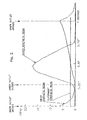
- FIG. 2 shows changes, over time, in the pressure of the outermost synthetic resin A in the outermost channel 4, the pressure of the outer synthetic resin B in the outer channel 6, and the pressure of the inner synthetic resin C in the inner channel 8 in the preferred embodiment.
- FIGS. 3(i) to 3(vi) show the states of the outermost synthetic resin A, the outer synthetic resin B, and the inner synthetic resin C in the outermost channel 4, the outer channel 6, and the inner channel 8 at various points in time.
- the opening and closing means 28 is brought to the open position at a point in time 0.0T in FIG. 2, whereby the inner outlet 8c is opened.
- the outer synthetic resin supply means 16 is not in operation.
- the opening and closing means 28 is brought to the open position to open the inner outlet 8c
- the inner synthetic resin C is flowed from the inner channel 8 into the discharge portion 4b of the outermost channel 4 via the discharge portion 6b of the outer channel 6, as shown in FIGS. 3(i) and 3(ii).
- the outer synthetic resin B flowed from the outer channel 6 is present at the center of the discharge portion 4b of the outer channel 4, and the outermost synthetic resin A is present in a peripheral edge portion of the discharge portion 4b of the outermost channel 4.
- the inner synthetic resin C is flowed into the outer synthetic resin B.
- the opening and closing means 28 is brought to the closed position to close the inner outlet 8c, as shown in FIG. 3(iii).
- the outer synthetic resin supply means 16 starts to be operated slightly before the point in time 0.25T (or at the point in time 0.25T), and its operation is stopped at a point in time 0.75T.
- the pressure of the outer synthetic resin B in the outer channel 6 gradually increases and then gradually decreases.
- the outer synthetic resin B flows from the outer channel 6 into the discharge portion 4b of the outermost channel 4, acts on the upstream side of the inner synthetic resin C previously flowed into the outer synthetic resin B, and fluidizes the inner synthetic resin C gradually downstream while shortening the length, in the flowing direction, of the inner synthetic resin C.
- the inner synthetic resin C in the discharge portion 4b of the outermost channel 4 is positioned between the outer synthetic resin B caused to inflow previously and the outer synthetic resin B caused to inflow subsequently at a time interval. Consequently, a state is achieved in which the outer synthetic resin B exists over a considerable length between the inner synthetic resin C caused to inflow previously and the inner synthetic resin C caused to inflow subsequently at a time interval.
- the inner synthetic resin supply means 22 is operated even while the opening and closing means 28 is kept at the closed position.
- the pressure of the inner synthetic resin C in the inner channel 8 is gradually increased.
- the opening and closing means 28 is brought to the open position at a point in time T, the inner synthetic resin C is flowed again from the inner channel 8 into the discharge portion 4b of the outermost channel 4 via the discharge portion 6b of the outer channel 6, and the pressure of the inner synthetic resin C in the inner channel 8 is gradually decreased. Since the outermost synthetic resin supply means 10 is continuously operated, the pressure of the outermost synthetic resin A in the outermost channel 4 is maintained at a substantially constant level.
- a composite synthetic resin consisting of the outermost synthetic resin A, the outer synthetic resin B and the inner synthetic resin C, which is flowed out of the outermost outlet 4c of the outermost channel 4, is cut at a site between two of the inner synthetic resins C to form a composite synthetic resin material D (FIG. 3(vi)). Cutting of the composite synthetic resin can be performed, for example, by a cutting member (not shown) which is moved across the outermost outlet 4c.
- the inner synthetic resin C is completely wrapped in the outer synthetic resin B and the outermost synthetic resin A, as will be clearly understood from FIG. 3(vi).
- the inner synthetic resin C tends to have an upstream side rendered somewhat concave under the action of the outer synthetic resin B.
- the composite synthetic resin material D can be used preferably as a composite synthetic resin material which is formed into a preform by compression molding.
- the outermost channel 4 is also disposed in addition to the inner channel 8 and the outer channel 6. If desired, however, it is permissible to omit the outermost channel 4 and the outermost synthetic resin supply means 10 disposed in associated therewith.
- the discharge portion of the outer channel 6 is configured to have an upstream part of a relatively small diameter (corresponding to the discharge portion 6b of the outer channel 6 in FIG. 1) and a downstream part of a relatively large diameter (corresponding to the discharge portion 4b of the outermost channel 4 in FIG. 1).
- a two-layer composite synthetic resin material is formed in which the inner synthetic resin C is wrapped in the outer synthetic resin B and the outermost synthetic resin A (the outer synthetic resin B and the outermost synthetic resin A may be the same).
- the present invention can be applied to the formation of a composite synthetic resin material of three or more layers in which the inner synthetic resin C itself has wrapped therein another layer or a plurality of other layers of synthetic resin.
- the relation between the flow of the inner synthetic resin C and the flow of the other synthetic resin wrapped therein can be rendered substantially the same as the relation between the flow of the outer synthetic resin B (and the outermost synthetic resin A) and the flow of the inner synthetic resin C in the illustrated embodiment.
- FIGS. 4(i) and 4(ii) show a modification of the outer synthetic resin supply means.
- This outer synthetic resin supply means 116 is constructed of an extruder 118, two plunger means 119a and 119b, and a switching means 121.
- the switching means 121 which can be constructed of a valve having two communication passages, is alternately set in a first state shown in FIG. 4(i) and a second state shown in FIG. 4(ii).
- the switching means 121 is set in the first state shown in FIG. 4(i)
- the plunger 119a is in communication with the extruder 118, and synthetic resin extruded from the extruder 118 is accumulated in the plunger 119a.
- the plunger 119b is in communication with the outer channel 6 (FIG. 1) and, at a required point in time, a piston actuating means (not shown) is actuated to advance the piston of the plunger 119b (move it rightward in FIG. 4(i)), whereby the synthetic resin accumulated in the plunger 119b is supplied into the outer channel 6 (FIG. 1).
- the switching means 121 is set in the second state shown in FIG. 4(ii)
- the plunger 119a is brought into communication with the outer channel 6 (FIG. 1) and, at a required point in time, a piston actuating means (not shown) is actuated to advance the piston of the plunger 119a (move it leftward in FIG.
- the plunger 119b is in communication with the extruder 118, and the synthetic resin extruded from the extruder 118 is accumulated in the plunger 119b.
- a gear pump can be disposed between the extruder 118 and the switching means 121 to render the flow of the synthetic resin toward the switching means 121 uniform and smooth.
- FIG. 5 shows still another embodiment of the outer synthetic resin supply means.
- the outer synthetic resin supply means 216 is constructed of an extruder 218, and an intermittent communication means 219 disposed downstream of the extruder 218.
- the intermittent communication means 219 is constructed of a stationary member 223, where a communication passage 221 is formed, and a rotary member 227 where a communication passage 225 is formed.
- the rotary member 227 is rotated continuously or intermittently and, when the communication passage 225 formed in the rotary member 227 is intermittently brought into communication with the communication passage 221 formed in the stationary member 223, synthetic resin extruded from the extruder 218 is supplied into the outer channel 6 (FIG. 1) through the communication passages 221 and 225.
- a gear pump can be disposed between the extruder 218 and the intermittent communication means 219 to render the flow of the synthetic resin toward the intermittent communication means 219 uniform and smooth.
Landscapes
- Engineering & Computer Science (AREA)
- Mechanical Engineering (AREA)
- Manufacturing & Machinery (AREA)
- Extrusion Moulding Of Plastics Or The Like (AREA)
- Processing And Handling Of Plastics And Other Materials For Molding In General (AREA)
Abstract
Description
- This invention relates to a composite synthetic resin material formation method and apparatus for forming a composite synthetic resin material including an outer synthetic resin layer, and at least one inner synthetic resin layer wrapped in the outer synthetic resin layer.
- As well known among people skilled in the art, a composite synthetic resin material including an outer synthetic resin layer, and at least one inner synthetic resin layer wrapped in the outer synthetic resin layer is often used as a synthetic resin material for forming a preforming product (generally called a preform) to be blow molded into a beverage container, or for forming a container closure. Usually, a synthetic resin excellent in mechanical properties and hygienic properties is selected as the outer synthetic resin, while a synthetic resin excellent in gas barrier properties is selected as the inner synthetic resin.
- Japanese Published Unexamined Patent Application No. Hei 1-195016 discloses a composite synthetic resin material forming apparatus comprising an outermost channel having an outermost outlet, an outer channel having an outer outlet opening into the outermost channel, an inner channel having an inner outlet opening into the outer channel, an outermost synthetic resin supply means for flowing an outermost synthetic resin through the outermost channel, an outer synthetic resin supply means for flowing an outer synthetic resin through the outer channel, and an inner synthetic resin supply means for flowing an inner synthetic resin through the inner channel. The inner outlet has an opening and closing means annexed thereto for selectively opening and closing the inner outlet. In accordance with the opening and closing of the inner outlet by the opening and closing means, the inner synthetic resin is intermittently flowed from the inner channel into the outermost channel via the outer channel. This inner synthetic resin is wrapped in the outermost synthetic resin directly flowed into the outermost channel, and the outer synthetic resin (the outer synthetic resin and the outermost synthetic resin may be the same synthetic resin) flowed into the outermost channel via the outer channel. As a result, a composite synthetic resin material is flowed out of the outermost outlet.
- Japanese Published Unexamined Patent Application No. Hei 6-15715 also discloses a composite synthetic resin material forming apparatus comprising an outermost channel having an outermost outlet, an outer channel having an outer outlet opening into the outermost channel, an inner channel having an inner outlet opening into the outer channel, an outermost synthetic resin supply means for flowing an outermost synthetic resin through the outermost channel, an outer synthetic resin supply means for flowing an outer synthetic resin through the outer channel, and an inner synthetic resin supply means for flowing an inner synthetic resin through the inner channel. The outermost synthetic resin supply means is continuously operated to continuously flow the outermost synthetic resin directly into the outermost channel. The inner synthetic resin supply means is intermittently operated to intermittently flow the inner synthetic resin into the outermost channel via the outer channel. The outer synthetic resin supply means is intermittently operated a required time behind the intermittent operation of the inner synthetic resin supply means to intermittently flow the outer synthetic resin (the outer synthetic resin and the outermost synthetic resin may be the same synthetic resin) into the outer channel.
- However, the composite synthetic resin material forming apparatus disclosed in the aforementioned Japanese Published Unexamined Patent Application No. Hei 1-195016 has the following problems to be solved: Particularly when the composite synthetic resin material is to be flowed out of the outermost outlet at a relatively high speed, the inner synthetic resin, which has been wrapped in the outermost synthetic resin and the outer synthetic resin, leaves a relatively long, thin trail in the flowing direction. Thus, the length, in the flowing direction, of a region where the inner synthetic resin is not present becomes markedly short. This makes it necessary to cut the composite synthetic resin in a markedly restricted region in the flowing direction of the composite synthetic resin, when cutting the composite synthetic resin, which has been discharged from the outermost outlet, in a direction perpendicular to the flowing direction to cut off the composite synthetic resin from the composite synthetic resin forming apparatus. Owing to a slight error in the cutting, therefore, it is highly likely that a defective composite synthetic resin material having the inner synthetic resin exposed at the cut surface will be formed.
- In the composite synthetic resin material forming apparatus disclosed in the above-described Japanese Published Unexamined Patent Application No. Hei 6-15715, the outer synthetic resin is intermittently caused to inflow a predetermined time behind the intermittent inflow of the inner synthetic resin to pressurize the inner synthetic resin from the upstream side in the flowing direction, thereby shortening the length, in the flowing direction, of the inner synthetic resin so that the above problem with the composite synthetic resin material forming apparatus disclosed in the aforementioned Japanese Published Unexamined Patent Application No. Hei 1-195016 can be solved. However, the composite synthetic resin material forming apparatus disclosed in the above-described Japanese Published Unexamined Patent Application No. Hei 6-15715 is still not fully satisfactory. Particularly when the composite synthetic resin is flowed at a considerably high velocity, the phenomenon of the inner synthetic resin leaving a long trail is not sufficiently suppressed, partly because no opening and closing means is annexed to the inner outlet. Thus, a relatively long, thin trail of the inner synthetic resin tends to be generated.
- It is a principal object of the present invention, therefore, to provide a novel and improved composite synthetic resin material forming method and apparatus which can sufficiently shorten the length, in the flowing direction, of the inner synthetic resin wrapped in the outer synthetic resin (or the outer synthetic resin and the outermost synthetic resin) even when the discharge speed of the composite synthetic resin is rendered fully high.
- The inventors conducted in-depth studies, and have found that the above principal object can be attained by selectively opening and closing an inner outlet, and intermittently supplying an outer synthetic resin into an outer channel in accordance with the opening and closing of the inner outlet, in a composite synthetic resin material forming mode in which the outer synthetic resin is flowed through the outer channel having an outer outlet, and an inner synthetic resin is flowed through an inner channel having the inner outlet opening into the outer channel.
- According to a first aspect of the present invention, there is provided, as a composite synthetic resin material forming method for attaining the above principal object, a composite synthetic resin material forming method arranged to flow an outer synthetic resin through an outer channel having an outer outlet, and flow an inner synthetic resin through an inner channel having an inner outlet opening into the outer channel, the method comprising:
- selectively opening or closing the inner outlet; and
- intermittently supplying the outer synthetic resin into the outer channel in accordance with the opening or closing of the inner outlet.
- Furthermore, it is preferred for the method to include flowing an outermost synthetic resin through an outermost channel having an outermost outlet, and the outer outlet preferably opens into the outermost channel.
- According to a second aspect of the present invention, there is provided, as a composite synthetic resin material forming apparatus for attaining the above principal object, a composite synthetic resin material forming apparatus comprising:
- an outer channel having an outer outlet;
- an inner channel having an inner outlet opening into the outer channel;
- an outer synthetic resin supply means for flowing an outer synthetic resin through the outer channel; and
- an inner synthetic resin supply means for flowing an inner synthetic resin through Lhe inner channel, and
- further comprising an opening and closing means for selectively opening and closing the inner outlet, and wherein the outer synthetic resin supply means is intermittently operated in accordance with the opening and closing of the inner outlet by the opening and closing means to intermittently supply the outer synthetic resin into the outer channel.
- Preferably, the outer synthetic resin supply means starts the supply of the outer synthetic resin simultaneously with or before the closing of the inner outlet by the opening and closing means, and stops the supply of the outer synthetic resin simultaneously with or before the opening of the inner outlet by the opening and closing means. Preferably, the inner synthetic resin supply means is continuously operated. In preferred embodiments, the composite synthetic resin material forming apparatus further comprises an outermost channel having an outermost outlet, and an outermost synthetic resin supply means for flowing an outermost synthetic resin through the outermost channel, and the outer outlet opens into the outermost channel. The outermost synthetic resin supply means may be operated continuously or intermittently. The outer synthetic resin supply means can be constructed of an extruder which is continuously operated, and a gear pump connected downwardly of the extruder and intermittently operated. Alternatively, the outer synthetic resin supply means can be constructed of an extruder which is continuously operated, two plunger means, and a switching means which is alternately set in a first state where the switching means brings one of the plunger means into communication with the extruder, and brings the other plunger means into communication with the outer channel, and a second state where the switching means brings the one of the plunger means into communication with the outer channel, and brings the other plunger means into communication with the extruder. The outer synthetic resin supply means can be constructed of an extruder which is continuously operated, and an intermittent communications means which intermittently brings the extruder into communication with the outer channel. A composite synthetic resin material to be formed may be compression molded into a preforming product (usually called a preform) which is, for example, blow molded later into a container.
-
- FIG. 1 is a partial sectional view showing a main portion of a preferred embodiment of the composite synthetic resin material forming apparatus constructed in accordance with the present invention.
- FIG. 2 is a diagrammatic view showing changes in the pressure of an outermost synthetic resin in an outermost channel, the pressure of an outer synthetic resin in an outer channel, and the pressure of an inner synthetic resin in an inner channel in the composite synthetic resin material forming apparatus of FIG. 1.
- FIGS. 3(i) to 3(vi) are partial sectional views showing the states of the outermost synthetic resin, the outer synthetic resin, and the inner synthetic resin in the outermost channel, the outer channel, and the inner channel at various points in time in the composite synthetic resin material forming apparatus of FIG. 1.
- FIGS. 4(i) and 4(ii) are schematic views showing a modification of outer synthetic resin supply means.
- FIG. 5 is a schematic view showing still another modification of the outer synthetic resin supply means.
- The preferred embodiments of the composite synthetic resin material forming method and apparatus constructed in accordance with the present invention will now be described in greater detail with reference to the accompanying drawings.
- FIG. 1 shows a main portion of the composite synthetic resin material forming apparatus constructed in accordance with the present invention. This apparatus has a nozzle means 2, only a tip portion of which is shown. In the nozzle means 2, which can be constructed by combining a plurality of members formable from a suitable metal, an
outermost channel 4, anouter channel 6, and aninner channel 8 are formed. Theoutermost channel 4 includes anintroduction portion 4a of an annular cross sectional shape, and adischarge portion 4b of a circular cross sectional shape. A downstream part of theintroduction portion 4a extends toward a downstream side progressively obliquely in a radially inward direction, and the downstream end of theintroduction portion 4a is connected to an upstream end peripheral edge portion of thedischarge portion 4b. Anoutermost outlet 4c is formed at the downstream end of thedischarge portion 4b. Theouter channel 6 similarly includes anintroduction portion 6a of an annular cross sectional shape, and adischarge portion 6b of a circular cross sectional shape. A downstream part of theintroduction portion 6a extends toward a downstream side progressively obliquely in a radially inward direction, and the downstream end of theintroduction portion 6a is connected to an upstream end peripheral edge portion of thedischarge portion 6b. Thedischarge portion 6b is relatively short, and anouter outlet 6c is formed at the downstream end of thedischarge portion 6b. Theouter outlet 6c is open at the upper end center of thedischarge portion 4b of theoutermost channel 4. Theinner channel 8 similarly includes anintroduction portion 8a of an annular cross sectional shape, and adischarge portion 8b of a circular cross sectional shape. A downstream part of theintroduction portion 8a extends toward a downstream side obliquely in a radially inward direction, and the downstream end of theintroduction portion 8a is connected to thedischarge portion 8b. Thedischarge portion 8b is relatively short, and aninner outlet 8c is formed at the downstream end of thedischarge portion 8b. Theinner outlet 8c is open at the upper end of thedischarge portion 6b of theouter channel 6. - With further reference to FIG. 1, the upstream end of the
outermost channel 4 is connected to an outermost synthetic resin supply means 10 via a suitable communication passage (not shown). The outermost synthetic resin supply means 10 includes anextruder 12, and agear pump 14 connected downstream of theextruder 12, whereby an outermost synthetic resin A (FIGS. 3(i) to 3(vi)) in a molten state extruded from theextruder 12 is supplied to theoutermost channel 4 via thegear pump 14. The upstream end of theouter channel 6 is connected to an outer synthetic resin supply means 16 via a suitable communication passage (not shown). The outer synthetic resin supply means 16 includes anextruder 18, and agear pump 20 connected downstream of theextruder 18, whereby an outer synthetic resin B (FIGS. 3(i) to 3(vi)) in a molten state extruded from theextruder 18 is supplied to theouter channel 6 via thegear pump 20. The outermost synthetic resin A and the outer synthetic resin B may be the same synthetic resin, which is advantageously polyester, especially, polyethylene terephthalate. The upstream end of theinner channel 8 is connected to an inner synthetic resin supply means 22. The inner synthetic resin supply means 22 includes anextruder 24, and a gear pump 26 connected downstream of theextruder 24, whereby an inner synthetic resin C (FIGS. 3(i) to 3(vi)) in a molten state extruded from theextruder 24 is supplied to theinner channel 8 via the gear pump 26. - In the apparatus constructed in accordance with the present invention, it is important to dispose an opening and closing means 28 for selectively opening and closing the
inner outlet 8c disposed at the downstream end of theinner channel 8. The opening and closing means 28 in the illustrated embodiment includes arod 30 and an operating means 32. Therod 30 has substantially the same external diameter as the internal diameter of thedischarge portion 8b of theinner channel 8, and has a front end portion of a conical shape. The operating means 32, which can be constructed of a cam mechanism or a fluid pressure cylinder mechanism, selectively locates therod 28 at an open position indicated by solid lines, and a closed position indicated by dashed double-dotted lines. When therod 28 is located at the open position, theinner outlet 8c disposed at the downstream end of theinner channel 8 is opened to bring theinner channel 8 into communication with theouter channel 6. When therod 28 is located at the closed position, theinner outlet 8c disposed at the downstream end of theinner channel 8 is closed to block theinner channel 8 from theouter channel 6. - In the above-described apparatus, the outermost synthetic resin supply means 10 is preferably operated continuously (the
extruder 12 is continuously operated, and thegear pump 14 is also continuously operated) to supply the outermost synthetic resin A continuously into theoutermost channel 4. If desired, the outermost synthetic resin supply means 10 can be operated intermittently (theextruder 12 is continuously operated, but thegear pump 14 is intermittently operated). Advantageously, the inner synthetic resin supply means 22 is also continuously operated (theextruder 24 is continuously operated, and the gear pump 26 is also continuously operated), but it is important that the opening and closing means 28 annexed to theinner channel 8 is located alternately at the open position and the closed position. When the opening and closing means 28 is located at the open position, the inner synthetic resin C supplied from the inner synthetic resin supply mean 22 into theinner channel 8 is flowed into thedischarge portion 4b of theoutermost channel 4 via thedischarge portion 6b of theouter channel 6. When the opening and closing means 28 is located at the closed position, theinner outlet 8c of theinner channel 8 is closed and, thus, the inner synthetic resin C does not flow into thedischarge portion 6b of theouter channel 6. On the other hand, it is important that the outer synthetic resin supply means 16 is intermittently operated in accordance with the opening and closing of the opening and closing means 28 annexed to the inner channel 8 (theextruder 18 is continuously operated, but the gear pump 26 is intermittently operated). Preferably, the outer synthetic resin supply means 16 starts to be operated simultaneously with or prior to the closure of theinner outlet 8c by the locating of the opening and closing means 28 at the closed position, and the operation of the outer synthetic resin supply means 16 is stopped simultaneously with or prior to the opening of theinner outlet 8c by the locating of the opening and closing means 28 at the open position. The duration of the time that the opening and closing means 28 is located at the closed position to keep theinner outlet 8c closed is advantageously of the order of 1 to 4 times the time duration for which the opening and closing means 28 is located at the open position to keep theinner outlet 8c open. - If the outermost synthetic resin supply means 10 and/or the inner synthetic resin supply means 22 are or is continuously operated to supply synthetic resin continuously, the
gear pump 14 and/or the gear pump 26 can be omitted if desired. To render the flow of the continuously supplied synthetic resin uniform and smooth, however, thegear pump 14 and/or the gear pump 26 should desirably be disposed. - FIG. 2 shows changes, over time, in the pressure of the outermost synthetic resin A in the
outermost channel 4, the pressure of the outer synthetic resin B in theouter channel 6, and the pressure of the inner synthetic resin C in theinner channel 8 in the preferred embodiment. FIGS. 3(i) to 3(vi) show the states of the outermost synthetic resin A, the outer synthetic resin B, and the inner synthetic resin C in theoutermost channel 4, theouter channel 6, and theinner channel 8 at various points in time. With further reference to FIGS. 2 and FIGS. 3(i) to 3(vi) along with FIG. 1, in the illustrated embodiment, the opening and closing means 28 is brought to the open position at a point in time 0.0T in FIG. 2, whereby theinner outlet 8c is opened. At this point in time, the outer synthetic resin supply means 16 is not in operation. When the opening and closing means 28 is brought to the open position to open theinner outlet 8c, the inner synthetic resin C is flowed from theinner channel 8 into thedischarge portion 4b of theoutermost channel 4 via thedischarge portion 6b of theouter channel 6, as shown in FIGS. 3(i) and 3(ii). The outer synthetic resin B flowed from theouter channel 6 is present at the center of thedischarge portion 4b of theouter channel 4, and the outermost synthetic resin A is present in a peripheral edge portion of thedischarge portion 4b of theoutermost channel 4. Thus, the inner synthetic resin C is flowed into the outer synthetic resin B. - At a point in time 0.25T in FIG. 2, the opening and closing means 28 is brought to the closed position to close the
inner outlet 8c, as shown in FIG. 3(iii). Thus, inflow of the inner synthetic resin C from theinner channel 8 into theouter channel 6 and theoutermost channel 4 is stopped. On the other hand, the outer synthetic resin supply means 16 starts to be operated slightly before the point in time 0.25T (or at the point in time 0.25T), and its operation is stopped at a point in time 0.75T. Thus, during the period from the start of operation to the stoppage of operation of the outer synthetic resin supply means 16, the pressure of the outer synthetic resin B in theouter channel 6 gradually increases and then gradually decreases. During the operation of the outer synthetic resin supply means 16, as will be understood by reference to FIGS. 3(iv), 3(v) and 3(vi), the outer synthetic resin B flows from theouter channel 6 into thedischarge portion 4b of theoutermost channel 4, acts on the upstream side of the inner synthetic resin C previously flowed into the outer synthetic resin B, and fluidizes the inner synthetic resin C gradually downstream while shortening the length, in the flowing direction, of the inner synthetic resin C. As a result, the inner synthetic resin C in thedischarge portion 4b of theoutermost channel 4 is positioned between the outer synthetic resin B caused to inflow previously and the outer synthetic resin B caused to inflow subsequently at a time interval. Consequently, a state is achieved in which the outer synthetic resin B exists over a considerable length between the inner synthetic resin C caused to inflow previously and the inner synthetic resin C caused to inflow subsequently at a time interval. - The inner synthetic resin supply means 22 is operated even while the opening and closing means 28 is kept at the closed position. Thus, during the period from locating of the opening and closing means 28 at the closed position until re-locating of the opening and closing means 28 at the open position, the pressure of the inner synthetic resin C in the
inner channel 8 is gradually increased. When the opening and closing means 28 is brought to the open position at a point in time T, the inner synthetic resin C is flowed again from theinner channel 8 into thedischarge portion 4b of theoutermost channel 4 via thedischarge portion 6b of theouter channel 6, and the pressure of the inner synthetic resin C in theinner channel 8 is gradually decreased. Since the outermost synthetic resin supply means 10 is continuously operated, the pressure of the outermost synthetic resin A in theoutermost channel 4 is maintained at a substantially constant level. - A composite synthetic resin, consisting of the outermost synthetic resin A, the outer synthetic resin B and the inner synthetic resin C, which is flowed out of the
outermost outlet 4c of theoutermost channel 4, is cut at a site between two of the inner synthetic resins C to form a composite synthetic resin material D (FIG. 3(vi)). Cutting of the composite synthetic resin can be performed, for example, by a cutting member (not shown) which is moved across theoutermost outlet 4c. In the resulting composite synthetic resin material D, the inner synthetic resin C is completely wrapped in the outer synthetic resin B and the outermost synthetic resin A, as will be clearly understood from FIG. 3(vi). In addition, the inner synthetic resin C tends to have an upstream side rendered somewhat concave under the action of the outer synthetic resin B. Thus, the composite synthetic resin material D can be used preferably as a composite synthetic resin material which is formed into a preform by compression molding. - In the illustrated preferred embodiment, the
outermost channel 4 is also disposed in addition to theinner channel 8 and theouter channel 6. If desired, however, it is permissible to omit theoutermost channel 4 and the outermost synthetic resin supply means 10 disposed in associated therewith. In this case, in order that the inner synthetic resin C is reliably wrapped in the outer synthetic resin B, it is advantageous that the discharge portion of theouter channel 6 is configured to have an upstream part of a relatively small diameter (corresponding to thedischarge portion 6b of theouter channel 6 in FIG. 1) and a downstream part of a relatively large diameter (corresponding to thedischarge portion 4b of theoutermost channel 4 in FIG. 1). In the illustrated embodiment, moreover, a two-layer composite synthetic resin material is formed in which the inner synthetic resin C is wrapped in the outer synthetic resin B and the outermost synthetic resin A (the outer synthetic resin B and the outermost synthetic resin A may be the same). If desired, however, the present invention can be applied to the formation of a composite synthetic resin material of three or more layers in which the inner synthetic resin C itself has wrapped therein another layer or a plurality of other layers of synthetic resin. In this case, the relation between the flow of the inner synthetic resin C and the flow of the other synthetic resin wrapped therein can be rendered substantially the same as the relation between the flow of the outer synthetic resin B (and the outermost synthetic resin A) and the flow of the inner synthetic resin C in the illustrated embodiment. - FIGS. 4(i) and 4(ii) show a modification of the outer synthetic resin supply means. This outer synthetic resin supply means 116 is constructed of an
extruder 118, two plunger means 119a and 119b, and a switching means 121. The switching means 121, which can be constructed of a valve having two communication passages, is alternately set in a first state shown in FIG. 4(i) and a second state shown in FIG. 4(ii). When the switching means 121 is set in the first state shown in FIG. 4(i), theplunger 119a is in communication with theextruder 118, and synthetic resin extruded from theextruder 118 is accumulated in theplunger 119a. Theplunger 119b is in communication with the outer channel 6 (FIG. 1) and, at a required point in time, a piston actuating means (not shown) is actuated to advance the piston of theplunger 119b (move it rightward in FIG. 4(i)), whereby the synthetic resin accumulated in theplunger 119b is supplied into the outer channel 6 (FIG. 1). When the switching means 121 is set in the second state shown in FIG. 4(ii), theplunger 119a is brought into communication with the outer channel 6 (FIG. 1) and, at a required point in time, a piston actuating means (not shown) is actuated to advance the piston of the plunger 119a (move it leftward in FIG. 4(ii)), whereby the synthetic resin accumulated in theplunger 119a is supplied into the outer channel 6 (FIG. 1). Theplunger 119b is in communication with theextruder 118, and the synthetic resin extruded from theextruder 118 is accumulated in theplunger 119b. If desired, a gear pump can be disposed between theextruder 118 and the switching means 121 to render the flow of the synthetic resin toward the switching means 121 uniform and smooth. - FIG. 5 shows still another embodiment of the outer synthetic resin supply means. The outer synthetic resin supply means 216 is constructed of an
extruder 218, and an intermittent communication means 219 disposed downstream of theextruder 218. The intermittent communication means 219 is constructed of astationary member 223, where acommunication passage 221 is formed, and arotary member 227 where acommunication passage 225 is formed. Therotary member 227 is rotated continuously or intermittently and, when thecommunication passage 225 formed in therotary member 227 is intermittently brought into communication with thecommunication passage 221 formed in thestationary member 223, synthetic resin extruded from theextruder 218 is supplied into the outer channel 6 (FIG. 1) through thecommunication passages extruder 218 and the intermittent communication means 219 to render the flow of the synthetic resin toward the intermittent communication means 219 uniform and smooth.
Claims (11)
- A composite synthetic resin material forming method arranged to flow an outer synthetic resin through an outer channel having an outer outlet, and flow an inner synthetic resin through an inner channel having an inner outlet opening into the outer channel, and comprising:selectively opening and closing the inner outlet; andintermittently supplying the outer synthetic resin into the outer channel in accordance with opening and closing of the inner outlet.
- The composite synthetic resin material forming method according to claim 1, further comprising flowing an outermost synthetic resin through an outermost channel having an outermost outlet, and wherein the outer outlet opens into the outermost channel.
- A composite synthetic resin material forming apparatus comprising:an outer channel having an outer outlet;an inner channel having an inner outlet opening into the outer channel;outer synthetic resin supply means for flowing an outer synthetic resin through the outer channel; andinner synthetic resin supply means for flowing an inner synthetic resin through the inner channel, andfurther comprising opening and closing means for selectively opening and closing the inner outlet, and wherein the outer synthetic resin supply means intermittently supplies the outer synthetic resin to the outer channel in accordance with opening and closing of the inner outlet by the opening and closing means.
- The composite synthetic resin material forming apparatus according to claim 3, wherein the outer synthetic resin supply means starts supply of the outer synthetic resin simultaneously with or before the closing of the inner outlet by the opening and closing means, and stops the supply of the outer synthetic resin simultaneously with or before the opening of the inner outlet by the opening and closing means.
- The composite synthetic resin material forming apparatus according to claim 3 or 4, wherein the inner synthetic resin supply means is continuously operated.
- The composite synthetic resin material forming apparatus according to any one of claims 3 to 5, further comprising an outermost channel having an outermost outlet and outermost synthetic resin supply means for flowing an outermost synthetic resin through the outermost channel, and wherein the outer outlet opens into the outermost channel.
- The composite synthetic resin material forming apparatus according to claim 6, wherein the outermost synthetic resin supply means is operated continuously or intermittently.
- The composite synthetic resin material forming apparatus according to any one of claims 3 to 7, wherein the outer synthetic resin supply means is constructed of an extruder which is continuously operated, and a gear pump connected downwardly of the extruder and intermittently operated.
- The composite synthetic resin material forming apparatus according to any one of claims 3 to 7, wherein the outer synthetic resin supply means is constructed of an extruder which is continuously operated, two plunger means, and switching means which is alternately set in a first state where the switching means brings one of the plunger means into communication with the extruder, and brings other of the plunger means into communication with the outer channel, and a second state where the switching means brings the one of the plunger means into communication with the outer channel, and brings the other of the plunger means into communication with the extruder.
- The composite synthetic resin material forming apparatus according to any one of claims 3 to 7, wherein the outer synthetic resin supply means is constructed of an extruder which is continuously operated, and intermittent communications means which intermittently brings the extruder into communication with the outer channel.
- The composite synthetic resin material forming apparatus according to any one of claims 3 to 10, wherein a composite synthetic resin material to be formed is compression molded into a required form.
Applications Claiming Priority (2)
| Application Number | Priority Date | Filing Date | Title |
|---|---|---|---|
| JP2003014472 | 2003-01-23 | ||
| PCT/JP2004/000530 WO2004065101A1 (en) | 2003-01-23 | 2004-01-22 | Method and device for forming composite synthetic resin material |
Publications (3)
| Publication Number | Publication Date |
|---|---|
| EP1612029A1 true EP1612029A1 (en) | 2006-01-04 |
| EP1612029A4 EP1612029A4 (en) | 2012-02-08 |
| EP1612029B1 EP1612029B1 (en) | 2019-01-09 |
Family
ID=32767403
Family Applications (1)
| Application Number | Title | Priority Date | Filing Date |
|---|---|---|---|
| EP04704327.8A Expired - Lifetime EP1612029B1 (en) | 2003-01-23 | 2004-01-22 | Method and device for forming composite synthetic resin material |
Country Status (8)
| Country | Link |
|---|---|
| US (1) | US7341684B2 (en) |
| EP (1) | EP1612029B1 (en) |
| JP (1) | JP4449904B2 (en) |
| KR (1) | KR100977820B1 (en) |
| CN (1) | CN1741891B (en) |
| AU (1) | AU2004205594B8 (en) |
| CA (1) | CA2513994A1 (en) |
| WO (1) | WO2004065101A1 (en) |
Cited By (1)
| Publication number | Priority date | Publication date | Assignee | Title |
|---|---|---|---|---|
| DE102011016761A1 (en) * | 2011-04-12 | 2012-10-18 | RWR Patentverwaltung GbR(vertreten durch Josef Rothen, 42699 Solingen, Michael Rothen, 40764 Langenfeld, Harald Wallner, 51371 Leverkusen) | Device, coextrusion nozzle and method for applying and / or producing a laminar composite material and planar composite material |
Families Citing this family (6)
| Publication number | Priority date | Publication date | Assignee | Title |
|---|---|---|---|---|
| JP4442325B2 (en) | 2004-05-31 | 2010-03-31 | 東洋製罐株式会社 | Method for producing multilayer structure |
| AU2005324740B2 (en) * | 2005-01-12 | 2009-09-24 | Toyo Seikan Kaisha, Ltd. | Extrusion feed device for composite resin and composite resin lump |
| US8765038B2 (en) | 2006-04-27 | 2014-07-01 | Toyo Seikan Kaisha, Ltd. | Method of feeding composite molten resin and apparatus for feeding the same |
| CN101400227B (en) * | 2007-09-24 | 2011-10-19 | 黄强 | Glue dropping method of composite conductive sealing adhesive strip |
| US20090230081A1 (en) * | 2008-03-12 | 2009-09-17 | Vinperfect Inc. | Vented screwcap closure with diffusive membrane liner |
| JP6175978B2 (en) * | 2013-08-23 | 2017-08-09 | 東洋製罐グループホールディングス株式会社 | Composite synthetic resin extrusion head |
Family Cites Families (12)
| Publication number | Priority date | Publication date | Assignee | Title |
|---|---|---|---|---|
| US4056344A (en) * | 1970-09-01 | 1977-11-01 | Lemelson Jerome H | Apparatus for producing composite extrusions |
| US4149839A (en) * | 1975-12-30 | 1979-04-17 | Ishikawajima-Harima Jukogyo Kabushiki Kaisha | Blow molding apparatus |
| US4934915A (en) * | 1983-04-13 | 1990-06-19 | American National Can Company | Apparatus for injection molding multi-layer articles |
| JPS61158409A (en) * | 1984-12-29 | 1986-07-18 | Ishikawajima Harima Heavy Ind Co Ltd | Filling method of resin in multi-layer blow molding device |
| GB8616460D0 (en) * | 1986-07-05 | 1986-08-13 | Metal Box Plc | Manufacture of articles |
| US4906421A (en) * | 1987-07-01 | 1990-03-06 | Avery International Corporation | Process for making high performance pressure sensitive adhesive tapes |
| JPH0649318B2 (en) * | 1988-01-30 | 1994-06-29 | 東洋製罐株式会社 | Nozzle device for composite synthetic resin extrusion |
| US5162121A (en) * | 1988-01-30 | 1992-11-10 | Toyo Seikan Kaisha, Ltd. | Apparatus for extruding multiple synthetic resins |
| US5350211A (en) * | 1991-09-30 | 1994-09-27 | Tokai Kogyo Kabushiki Kaisha | Windshield molding for vehicles and the production method thereof |
| JP2500724B2 (en) * | 1992-04-06 | 1996-05-29 | 東洋製罐株式会社 | Method and apparatus for forming composite synthetic resin material |
| US6655945B1 (en) * | 1999-03-18 | 2003-12-02 | Mold Masters Limited | Apparatus and method for multi-layer injection molding |
| JP3514674B2 (en) | 1999-09-21 | 2004-03-31 | 株式会社プラ技研 | Extrusion molding equipment for resin multiple tubes |
-
2004
- 2004-01-22 JP JP2005508115A patent/JP4449904B2/en not_active Expired - Lifetime
- 2004-01-22 EP EP04704327.8A patent/EP1612029B1/en not_active Expired - Lifetime
- 2004-01-22 KR KR1020057013427A patent/KR100977820B1/en not_active Expired - Fee Related
- 2004-01-22 CN CN2004800025963A patent/CN1741891B/en not_active Expired - Lifetime
- 2004-01-22 WO PCT/JP2004/000530 patent/WO2004065101A1/en not_active Ceased
- 2004-01-22 CA CA002513994A patent/CA2513994A1/en not_active Abandoned
- 2004-01-22 US US10/543,211 patent/US7341684B2/en not_active Expired - Fee Related
- 2004-01-22 AU AU2004205594A patent/AU2004205594B8/en not_active Ceased
Cited By (1)
| Publication number | Priority date | Publication date | Assignee | Title |
|---|---|---|---|---|
| DE102011016761A1 (en) * | 2011-04-12 | 2012-10-18 | RWR Patentverwaltung GbR(vertreten durch Josef Rothen, 42699 Solingen, Michael Rothen, 40764 Langenfeld, Harald Wallner, 51371 Leverkusen) | Device, coextrusion nozzle and method for applying and / or producing a laminar composite material and planar composite material |
Also Published As
| Publication number | Publication date |
|---|---|
| EP1612029A4 (en) | 2012-02-08 |
| WO2004065101A1 (en) | 2004-08-05 |
| AU2004205594B8 (en) | 2008-10-09 |
| JPWO2004065101A1 (en) | 2006-05-18 |
| CN1741891B (en) | 2010-06-09 |
| AU2004205594A1 (en) | 2004-08-05 |
| KR100977820B1 (en) | 2010-08-25 |
| KR20050094453A (en) | 2005-09-27 |
| CN1741891A (en) | 2006-03-01 |
| JP4449904B2 (en) | 2010-04-14 |
| US7341684B2 (en) | 2008-03-11 |
| AU2004205594B2 (en) | 2008-09-04 |
| CA2513994A1 (en) | 2004-08-05 |
| EP1612029B1 (en) | 2019-01-09 |
| US20060051444A1 (en) | 2006-03-09 |
Similar Documents
| Publication | Publication Date | Title |
|---|---|---|
| US6349886B1 (en) | Injector nozzle and method | |
| EP1334786B1 (en) | Mold cooling device | |
| US7341684B2 (en) | Composite synthetic resin material forming method and apparatus | |
| KR920019519A (en) | Extrusion Control Method of Multi-Layered Parison | |
| KR20180101993A (en) | Device of controlling gate valves in a hot runner injection mold having multiple gate valves | |
| CN110520269B (en) | Dual seal valve pin tip with vent | |
| JP2009131901A (en) | Molding agent injection device for casting machine | |
| JPH08198233A (en) | Laminate peeling bottle, manufacturing method thereof, and die head assembly | |
| JP2011104807A (en) | Method and apparatus for producing composite synthetic resin | |
| US5403529A (en) | Method for forming composite synthetic resin material | |
| JP2002513694A (en) | Filter device for extrusion and injection molding machines | |
| SE500303C2 (en) | Device for making hollow plastic articles by injection molding | |
| JP4407796B2 (en) | Parison molding method and apparatus | |
| JP2832504B2 (en) | Apparatus for producing a flowable reaction mixture from at least two flowable reaction components that react with each other to a bulk or foam material | |
| KR101322047B1 (en) | Open gate typed hot runner injection molding apparatus having undercut nozzle tip | |
| JP2792590B2 (en) | Die for blow molding | |
| CA2523708C (en) | Apparatus for producing a tubular body | |
| JP4822948B2 (en) | Rubber coating apparatus and rubber coating cord manufacturing method | |
| JPH07171879A (en) | Multi-layer blow molding dies | |
| JPH09131758A (en) | Method for manufacturing synthetic resin molded body | |
| JPS6076315A (en) | Composite nozzle uniting and guiding at least two fluid reaction component for manufacturing fluid reaction mixture reacting so as to form plastic, particularly, foam plastic | |
| JPH11151735A (en) | Projection device for injection molded products | |
| JP2795371B2 (en) | Multilayer blow molding method | |
| KR100583770B1 (en) | Valve device for injection molding machine to prevent sprue | |
| JP4243840B2 (en) | Extrusion feeder |
Legal Events
| Date | Code | Title | Description |
|---|---|---|---|
| PUAI | Public reference made under article 153(3) epc to a published international application that has entered the european phase |
Free format text: ORIGINAL CODE: 0009012 |
|
| 17P | Request for examination filed |
Effective date: 20050718 |
|
| AK | Designated contracting states |
Kind code of ref document: A1 Designated state(s): AT BE BG CH CY CZ DE DK EE ES FI FR GB GR HU IE IT LI LU MC NL PT RO SE SI SK TR |
|
| AX | Request for extension of the european patent |
Extension state: AL LT LV MK |
|
| DAX | Request for extension of the european patent (deleted) | ||
| RBV | Designated contracting states (corrected) |
Designated state(s): DE FR GB IT |
|
| A4 | Supplementary search report drawn up and despatched |
Effective date: 20120105 |
|
| RIC1 | Information provided on ipc code assigned before grant |
Ipc: B29C 47/12 20060101ALI20111230BHEP Ipc: B29B 11/10 20060101ALI20111230BHEP Ipc: B29C 47/10 20060101AFI20111230BHEP Ipc: B29C 47/06 20060101ALI20111230BHEP Ipc: B29C 47/58 20060101ALI20111230BHEP Ipc: B29C 47/04 20060101ALI20111230BHEP |
|
| RAP1 | Party data changed (applicant data changed or rights of an application transferred) |
Owner name: TOYO SEIKAN KAISHA, LTD. |
|
| 17Q | First examination report despatched |
Effective date: 20140429 |
|
| GRAP | Despatch of communication of intention to grant a patent |
Free format text: ORIGINAL CODE: EPIDOSNIGR1 |
|
| INTG | Intention to grant announced |
Effective date: 20180620 |
|
| RIN1 | Information on inventor provided before grant (corrected) |
Inventor name: WATANABE, KAZUNOBU, TOYO SEIKAN GROUP Inventor name: KOMATSU, IKUO, TOYO SEIKAN GROUP Inventor name: FUKABORI, HOTAKA, TOYO SEIKAN GROUP Inventor name: IMATANI, TSUNEO, TOYO SEIKAN GROUP Inventor name: ETOH, MAKOTO, TOYO SEIKAN GROUP |
|
| GRAJ | Information related to disapproval of communication of intention to grant by the applicant or resumption of examination proceedings by the epo deleted |
Free format text: ORIGINAL CODE: EPIDOSDIGR1 |
|
| GRAP | Despatch of communication of intention to grant a patent |
Free format text: ORIGINAL CODE: EPIDOSNIGR1 |
|
| INTC | Intention to grant announced (deleted) | ||
| INTG | Intention to grant announced |
Effective date: 20180913 |
|
| GRAS | Grant fee paid |
Free format text: ORIGINAL CODE: EPIDOSNIGR3 |
|
| GRAA | (expected) grant |
Free format text: ORIGINAL CODE: 0009210 |
|
| AK | Designated contracting states |
Kind code of ref document: B1 Designated state(s): DE FR GB IT |
|
| REG | Reference to a national code |
Ref country code: GB Ref legal event code: FG4D |
|
| REG | Reference to a national code |
Ref country code: DE Ref legal event code: R096 Ref document number: 602004053618 Country of ref document: DE |
|
| RAP2 | Party data changed (patent owner data changed or rights of a patent transferred) |
Owner name: TOYO SEIKAN GROUP HOLDINGS, LTD. |
|
| PGFP | Annual fee paid to national office [announced via postgrant information from national office to epo] |
Ref country code: DE Payment date: 20190130 Year of fee payment: 16 Ref country code: GB Payment date: 20190218 Year of fee payment: 16 Ref country code: FR Payment date: 20190130 Year of fee payment: 16 |
|
| PGFP | Annual fee paid to national office [announced via postgrant information from national office to epo] |
Ref country code: IT Payment date: 20190430 Year of fee payment: 16 |
|
| REG | Reference to a national code |
Ref country code: DE Ref legal event code: R097 Ref document number: 602004053618 Country of ref document: DE |
|
| PLBE | No opposition filed within time limit |
Free format text: ORIGINAL CODE: 0009261 |
|
| STAA | Information on the status of an ep patent application or granted ep patent |
Free format text: STATUS: NO OPPOSITION FILED WITHIN TIME LIMIT |
|
| 26N | No opposition filed |
Effective date: 20191010 |
|
| REG | Reference to a national code |
Ref country code: DE Ref legal event code: R119 Ref document number: 602004053618 Country of ref document: DE |
|
| GBPC | Gb: european patent ceased through non-payment of renewal fee |
Effective date: 20200122 |
|
| PG25 | Lapsed in a contracting state [announced via postgrant information from national office to epo] |
Ref country code: GB Free format text: LAPSE BECAUSE OF NON-PAYMENT OF DUE FEES Effective date: 20200122 Ref country code: DE Free format text: LAPSE BECAUSE OF NON-PAYMENT OF DUE FEES Effective date: 20200801 Ref country code: FR Free format text: LAPSE BECAUSE OF NON-PAYMENT OF DUE FEES Effective date: 20200131 |
|
| PG25 | Lapsed in a contracting state [announced via postgrant information from national office to epo] |
Ref country code: IT Free format text: LAPSE BECAUSE OF NON-PAYMENT OF DUE FEES Effective date: 20200122 |