JP2009131901A - Mold release agent spraying device for casting machine - Google Patents
Mold release agent spraying device for casting machine Download PDFInfo
- Publication number
- JP2009131901A JP2009131901A JP2008306442A JP2008306442A JP2009131901A JP 2009131901 A JP2009131901 A JP 2009131901A JP 2008306442 A JP2008306442 A JP 2008306442A JP 2008306442 A JP2008306442 A JP 2008306442A JP 2009131901 A JP2009131901 A JP 2009131901A
- Authority
- JP
- Japan
- Prior art keywords
- release agent
- injection
- chamber
- metering
- release
- Prior art date
- Legal status (The legal status is an assumption and is not a legal conclusion. Google has not performed a legal analysis and makes no representation as to the accuracy of the status listed.)
- Pending
Links
Images


Classifications
-
- B—PERFORMING OPERATIONS; TRANSPORTING
- B22—CASTING; POWDER METALLURGY
- B22D—CASTING OF METALS; CASTING OF OTHER SUBSTANCES BY THE SAME PROCESSES OR DEVICES
- B22D17/00—Pressure die casting or injection die casting, i.e. casting in which the metal is forced into a mould under high pressure
- B22D17/20—Accessories: Details
- B22D17/2007—Methods or apparatus for cleaning or lubricating moulds
-
- B—PERFORMING OPERATIONS; TRANSPORTING
- B05—SPRAYING OR ATOMISING IN GENERAL; APPLYING FLUENT MATERIALS TO SURFACES, IN GENERAL
- B05B—SPRAYING APPARATUS; ATOMISING APPARATUS; NOZZLES
- B05B12/00—Arrangements for controlling delivery; Arrangements for controlling the spray area
- B05B12/02—Arrangements for controlling delivery; Arrangements for controlling the spray area for controlling time, or sequence, of delivery
-
- B—PERFORMING OPERATIONS; TRANSPORTING
- B05—SPRAYING OR ATOMISING IN GENERAL; APPLYING FLUENT MATERIALS TO SURFACES, IN GENERAL
- B05B—SPRAYING APPARATUS; ATOMISING APPARATUS; NOZZLES
- B05B12/00—Arrangements for controlling delivery; Arrangements for controlling the spray area
- B05B12/08—Arrangements for controlling delivery; Arrangements for controlling the spray area responsive to condition of liquid or other fluent material to be discharged, of ambient medium or of target ; responsive to condition of spray devices or of supply means, e.g. pipes, pumps or their drive means
- B05B12/085—Arrangements for controlling delivery; Arrangements for controlling the spray area responsive to condition of liquid or other fluent material to be discharged, of ambient medium or of target ; responsive to condition of spray devices or of supply means, e.g. pipes, pumps or their drive means responsive to flow or pressure of liquid or other fluent material to be discharged
- B05B12/087—Flow or presssure regulators, i.e. non-electric unitary devices comprising a sensing element, e.g. a piston or a membrane, and a controlling element, e.g. a valve
- B05B12/088—Flow or presssure regulators, i.e. non-electric unitary devices comprising a sensing element, e.g. a piston or a membrane, and a controlling element, e.g. a valve the sensing element being a flexible member, e.g. membrane, diaphragm, bellows
-
- B—PERFORMING OPERATIONS; TRANSPORTING
- B05—SPRAYING OR ATOMISING IN GENERAL; APPLYING FLUENT MATERIALS TO SURFACES, IN GENERAL
- B05B—SPRAYING APPARATUS; ATOMISING APPARATUS; NOZZLES
- B05B7/00—Spraying apparatus for discharge of liquids or other fluent materials from two or more sources, e.g. of liquid and air, of powder and gas
- B05B7/02—Spray pistols; Apparatus for discharge
- B05B7/12—Spray pistols; Apparatus for discharge designed to control volume of flow, e.g. with adjustable passages
- B05B7/1254—Spray pistols; Apparatus for discharge designed to control volume of flow, e.g. with adjustable passages the controlling means being fluid actuated
- B05B7/1263—Spray pistols; Apparatus for discharge designed to control volume of flow, e.g. with adjustable passages the controlling means being fluid actuated pneumatically actuated
-
- B—PERFORMING OPERATIONS; TRANSPORTING
- B05—SPRAYING OR ATOMISING IN GENERAL; APPLYING FLUENT MATERIALS TO SURFACES, IN GENERAL
- B05B—SPRAYING APPARATUS; ATOMISING APPARATUS; NOZZLES
- B05B9/00—Spraying apparatus for discharge of liquids or other fluent material, without essentially mixing with gas or vapour
- B05B9/03—Spraying apparatus for discharge of liquids or other fluent material, without essentially mixing with gas or vapour characterised by means for supplying liquid or other fluent material
- B05B9/04—Spraying apparatus for discharge of liquids or other fluent material, without essentially mixing with gas or vapour characterised by means for supplying liquid or other fluent material with pressurised or compressible container; with pump
- B05B9/0403—Spraying apparatus for discharge of liquids or other fluent material, without essentially mixing with gas or vapour characterised by means for supplying liquid or other fluent material with pressurised or compressible container; with pump with pumps for liquids or other fluent material
- B05B9/0413—Spraying apparatus for discharge of liquids or other fluent material, without essentially mixing with gas or vapour characterised by means for supplying liquid or other fluent material with pressurised or compressible container; with pump with pumps for liquids or other fluent material with reciprocating pumps, e.g. membrane pump, piston pump, bellow pump
-
- B—PERFORMING OPERATIONS; TRANSPORTING
- B05—SPRAYING OR ATOMISING IN GENERAL; APPLYING FLUENT MATERIALS TO SURFACES, IN GENERAL
- B05B—SPRAYING APPARATUS; ATOMISING APPARATUS; NOZZLES
- B05B9/00—Spraying apparatus for discharge of liquids or other fluent material, without essentially mixing with gas or vapour
- B05B9/03—Spraying apparatus for discharge of liquids or other fluent material, without essentially mixing with gas or vapour characterised by means for supplying liquid or other fluent material
- B05B9/04—Spraying apparatus for discharge of liquids or other fluent material, without essentially mixing with gas or vapour characterised by means for supplying liquid or other fluent material with pressurised or compressible container; with pump
Abstract
Description
本発明は、請求項1のプリアンブル記載の鋳造機用の離型剤噴射装置に関する。
The present invention relates to a release agent injection device for a casting machine according to the preamble of
この種の離型剤噴射装置は、たとえば離型剤噴射システムとしてダイカスト機内の鋳型の自動化噴射に使用される。鋳造品質、耐用期間、保守、材料消費量および環境保護に対して進歩する要件と共に、それに対応して離型剤噴射システムに対する要件が増大する。 This type of release agent injection apparatus is used for, for example, automatic injection of a mold in a die casting machine as a release agent injection system. Along with the increasing requirements for casting quality, service life, maintenance, material consumption and environmental protection, there is a corresponding increase in requirements for the release agent injection system.
各噴射ノズルへ供給する遮断可能の離型剤供給通路が噴射中の一定の期間に対してのみ開放され、かつ噴射ノズルに同時に圧縮空気が供給され、その結果、離型剤が噴射ノズルの中へ吸引され、かつ該噴射ノズルから圧縮空気支援されて噴流として放出されることによって離型剤を1または複数本の噴射ノズルを介して断続的な噴射で放出することが知られている。特許文献1および特許文献2は、噴射ノズルへの離型剤供給通路の制御可能の開放および遮断のために制御空気によって作動可能の制御ピストンを設けたこの種の離型剤噴射装置を開示する。それによって噴射あたりに放出される離型剤の量は、特に制御ピストンの調整可能の行程と、該制御ピストンが離型剤供給通路を解放する該制御ピストンの開放時間とに左右される。離型剤圧力、形状および特に噴射ノズルの断面ならびに噴射ノズルに供給され、かつ離型剤を吸引する噴射空気押出のようなその他のパラメータへの付加的な依存性のために噴射および噴射ノズルあたりに噴射される離型剤量が前記従来の噴射システムでは正確に知られておらず、かつ正確に設定されてもいない。
The shut-off release agent supply passage for supplying to each injection nozzle is opened only for a certain period during injection, and compressed air is supplied to the injection nozzle at the same time. It is known that the release agent is discharged intermittently through one or a plurality of injection nozzles by being sucked into the nozzle and discharged as a jet flow with the aid of compressed air from the injection nozzle.
鋳造工程中の短いサイクル時間を達成するために、最新のダイカスト機に対してそれに対応する高速の離型剤噴射システムと、それによって非常に短い噴射時間が一様に優れた再現可能の噴射特性で要求されている。特に噴射特性と、とりわけ噴射された離型剤量は、遮断弁等の加わったシステム構成要素に生じ得る切換遅延によって影響を受けてはならない。さらに噴射された離型剤量は最小限に保持されるべきである。
本発明の技術的課題は、各噴射において設定可能な離型剤量の確実な放出を1または複数本の噴射ノズルを介して可能にする冒頭に挙げた形式の離型剤噴射装置の提供することである。 The technical problem of the present invention is to provide a release agent injection device of the type mentioned at the beginning which enables reliable release of a release agent amount that can be set in each injection via one or more injection nozzles. That is.
本発明は、請求項1の特徴を有する離型剤噴射装置の提供によって前記問題を解決する。この離型剤噴射装置において、放出手段が少なくとも1本の噴射ノズルに割り当てられ、かつ次の噴射で少なくとも1本の割り当てられた噴射ノズルによって放出される離型剤量を規定し、かつ離型剤供給から分離して次の噴射で放出するために供給するすくなくとも1つの配量ユニットを含む。
The present invention solves the above problem by providing a release agent injection device having the features of
このような本発明に係る離型剤噴射装置により、少ない噴射時間および/または低い離型剤圧力および/または比較的小さいノズル断面でも噴射あたりに比較的少ない離型剤量を正確に配量かつ放出することもできる。
配量ユニットによって一定に規定された次の噴射用の離型剤量は、離型剤源からの離型剤供給通路を介した離型剤の供給のような離型剤供給からは分離して提供され、次の噴射において、変動するパラメータ、および/または、正確に知られていない離型剤圧力、ノズル形状ならびにそれぞれ噴射ノズルに供給される噴射空気押出の圧力推移および期間のようなシステムパラメータに影響されることなく放出される。
噴射あたりの所望の離型剤量の正確な放出は、非常に短い噴射時間でも、切換遅延、または、その他の正確に知られていない、または、非再現性の、弁、制御ピストン等の加わったシステム構成要素の機能特性によって影響されない。
With such a release agent injection apparatus according to the present invention, a relatively small release agent amount can be accurately distributed per injection even with a short injection time and / or low release agent pressure and / or a relatively small nozzle cross section It can also be released.
The amount of release agent for the next injection that is fixed by the metering unit is separated from the release agent supply, such as the release agent supply via the release agent supply passage from the release agent source. Provided in the next injection, parameters such as fluctuating parameters and / or release agent pressure, nozzle shape and the pressure transition and duration of the injection air extrusion supplied to the injection nozzle respectively, which are not exactly known Released without being affected by parameters.
Accurate release of the desired amount of release agent per injection is possible even with very short injection times, addition of switching delays or other precisely unknown or non-reproducible valves, control pistons, etc. Not affected by the functional characteristics of the system components.
請求項2の態様においては、各量ユニットは遮断可能に離型剤供給通路を介して離型剤源に、かつノズル接続管を介して少なくとも1本の割り当てられた噴射ノズルに接続されている離型剤チャンバと、移動可能にかつそれによって前記離型剤チャンバを可変容積によって制限する配量要素とを包含する。この方法により次の噴射で1または複数本の割り当てられた噴射ノズルを介して放出される離型剤量を離型剤チャンバの中に貯蔵することができ、次いで該離型剤チャンバから前記離型剤量を次の噴射で放出することができる。 According to a second aspect of the present invention, each quantity unit is connected to a release agent source via a release agent supply passage and to at least one assigned injection nozzle via a nozzle connection pipe so as to be shut off. Including a release agent chamber and a dispensing element that is movable and thereby restricts said release agent chamber by a variable volume. In this way, the amount of release agent released through one or more assigned injection nozzles in the next injection can be stored in the release agent chamber and then released from the release agent chamber. The amount of mold can be released in the next injection.
請求項3の態様では、各々1つの逆止弁が離型剤供給通路および/またはノズル接続管の中にある。この自動弁制御手段は次の噴射前の離型剤チャンバの中への離型剤の所望の供給と、次の噴射で1または複数本の割り当てられた噴射ノズルを介したそこに貯蔵された離型剤量の放出とを可能にし、離型剤が離型剤チャンバから離型剤供給通路もしくは離型剤源の中へ逆流しない。
請求項4の態様においては、配量要素は少なくとも1または複数本の該配量要素に割り当てられた噴射ノズルと共に1つの共通のハウジングボディの中にあり、その結果、前記配量要素は該当する噴射ノズルと一緒に1つの構造ユニットとして組み込むことができる。
In one embodiment of the present invention, each one check valve is in the release agent supply passage and / or the nozzle connection pipe. This automatic valve control means is stored in the desired supply of release agent into the release agent chamber prior to the next injection and via one or more assigned injection nozzles in the next injection. The release agent amount can be released, and the release agent does not flow back from the release agent chamber into the release agent supply passage or the release agent source.
In an embodiment of
請求項5記載の態様においては、配量ユニットは制御媒体源と接続される、配量要素を制御できる制御媒体チャンバを有する。
請求項6記載の態様においては、制御媒体源は少なくとも2つの異なる制御圧力により配量要素の制御された作動のための手段を有していてよく、第1の制御圧力は離型剤チャンバ内への離型剤の配量のための配量要素を駆動し、かつ第1の制御圧力と異なる第2の制御圧力が離型剤チャンバから配量された離型剤を放出するための配量要素を駆動する。
In an embodiment as claimed in
In an embodiment as claimed in
本発明の請求項7の態様においては、それぞれ次の噴射でおよび/または異なる配量ユニットから放出される離型剤量を可変調整するための放出手段が設置されている。このように必要に応じて、同一の噴射ノズルを介して様々な離型剤量を連続する噴射で噴射することができ、または平行の噴射で様々な離型剤量を種々の配量ユニットに割り当てられた噴射ノズルを介して噴射することができる。 According to the seventh aspect of the present invention, there is provided a discharge means for variably adjusting the amount of the release agent discharged in the next injection and / or from different dispensing units. Thus, if necessary, various release agent amounts can be injected by continuous injection through the same injection nozzle, or various release agent amounts can be distributed to various dispensing units by parallel injection. Injection can be performed through the assigned injection nozzle.
請求項8の態様においては、各配量ユニットの配量要素に離型剤チャンバの中へ配量されもしくは該離型剤チャンバから放出される離型剤量の可変調整のための調整可能の運動制限器が組み込まれている。これは、噴射あたりに放出される離型剤量の可変調整のための有利な簡単な措置である。
In an embodiment of
本発明の有利な実施態様は図面に表示し、かつ以下これを説明する。 Advantageous embodiments of the invention are shown in the drawings and will be described below.
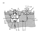
図1および2にそれぞれここで注目すべき構成要素と共に示した離型剤噴射装置は、たとえば金属ダイカスト用のダイカスト機において常用される離型剤もしくは離型媒体を、たとえば型表面に自動化して噴射するのに好適である。離型剤噴射装置は、それぞれ必要に応じて1または複数本の噴射ノズルを含み、それらのうち図1および2の正面図に噴射ノズル1が代表して示されている。各噴射ノズル1は、噴射ブロックもしくはハウジングボディ2の噴射側2aに取り付けられており、さらにその中に1または複数の配量ユニットが設けられており、それらのうち図1および2の正面図に図示した噴射ノズル1に割り当てられた配量ユニット3が代表して示されている。
The release agent injection device shown in FIGS. 1 and 2 together with the components to be noted here automates, for example, a release agent or a release medium commonly used in a die casting machine for metal die casting, for example, on the die surface. Suitable for spraying. The release agent injection device includes one or a plurality of injection nozzles as necessary, and the
図示した配量ユニット3は、配量要素として機能する軸線方向に移動可能に離型剤チャンバ6の中に配置された配量ピストン5と、制御媒体チャンバ7とに分割されたハウジングボディ2の中に設けられた中空チャンバ4を含む。制御媒体チャンバ7は制御媒体通路8を通して図示しない常用される制御媒体源に接続されている。圧縮空気またはその他のガス状または液状の制御媒体の供給または排出によって、制御媒体チャンバ7は選択的に加圧または減圧することができる。離型剤チャンバ6は離型剤供給通路9を通して図示しない常用される離型剤源に接続されている。逆止弁10は、離型剤を離型剤源から離型剤チャンバ6の中に給送できるが、離型剤チャンバ6から離型剤源への離型剤逆流が阻止されるように、離型剤供給通路9の中に配置されている。
The illustrated
噴射ノズル1はノズル接続管11を介して離型剤チャンバ6と接続されており、離型剤を離型剤チャンバ6から噴射ノズル1へ給送できるが、離型剤チャンバ6の中への逆流が阻止されるように、該ノズル接続管11の中に逆止弁12が配置されている。噴射支援媒体通路13を介して、平行に供給される液状の離型剤の噴射が生ぜしめられる、たとえば圧縮空気のような噴射支援媒体を供給できるようにするために図示しない常用される噴射支援媒体源に噴射ノズル1が接続されている。付属のノズル通路1aを備える好適な形状をもつ噴射ノズル1の形成によって、従来の方法で離型剤と噴射支援媒体、たとえば空気の混合と、所望の噴射効果とが生じる。
The
配量ピストン5から延伸しているピストン軸15は、密閉されて噴射側2aからハウジングボディ2の中へ取り付けられる穴16の中へ案内されている。ピストン軸15の中に前面側に外側からストッパ17aと共に可変調整可能のピストン行程制限器として機能する調整ネジ17が固定されている。その反対側では配量ピストン5がコイルバネ18上に支持されており、該コイルバネは該バネ側で離型剤チャンバ6の底面19に支持され、かつピストン軸端部20によって側面支承体に対して固定されている。
The
それぞれの必要性と適用事例に応じて、各々1つの配量ユニットは個別的に1本の噴射ノズルに割り当てることができる。すなわち、この場合においては1本のみの噴射ノズルが該当する配量ユニットの離型剤チャンバに接続されている。代替的に複数本の噴射ノズルを平行に1つの配量ユニットに接続してもよい。別の言葉を用いれば、本発明の好適な実施態様において所定の噴射ノズルの本数および配列において、ただ1つの配量ユニットが全噴射ノズルに対してまたは多数の噴射ノズルの1本をそれぞれ1本の噴射ノズルに割り当てられた配量ユニットの対応する数または複数の配量ユニットのうち少なくとも1つが複数の噴射ノズルに割り当てられた配量ユニットが設けられている。その際同様にそれぞれの必要性と適用事例とに応じて、各々1つの配量ユニットと該配量ユニットに割り当てられた噴射ノズル(群)を図示したように1つの共通の噴射ブロックモジュール体の中に組み込むことができ、その場合に全噴射システムをモジュール式に複数の噴射ブロックモジュールから構成することができ、または代替的には全部またはいずれにせよ複数の配量ユニットを該配量ユニットに接続された噴射ノズルと共に1つの噴射ブロックの中に組み込まれている。複数の配量ユニットが有る場合、前記配量ユニットは同一または別々に組み込むことができる。たとえば、それぞれ個別的に規定可能の噴射ノズルの本数が割り当てられた離型剤チャンバの同一または異なる断面を有する複数の配量ユニットを設けることができる。 Depending on the respective needs and application examples, each one dispensing unit can be individually assigned to one injection nozzle. That is, in this case, only one injection nozzle is connected to the release agent chamber of the corresponding dispensing unit. Alternatively, a plurality of spray nozzles may be connected in parallel to one dispensing unit. In other words, in a preferred embodiment of the present invention, in a given number and arrangement of injection nozzles, only one dispensing unit can be used for all injection nozzles or for each of a number of injection nozzles. A metering unit is provided in which at least one of a plurality of metering units or a plurality of metering units allocated to a plurality of spray nozzles is allocated to a plurality of spray nozzles. In the same way, according to the respective needs and application examples, one common dispensing block module body as shown in the figure, each with one dispensing unit and the injection nozzle (s) assigned to the dispensing unit. In which case the entire injection system can be modularly composed of a plurality of injection block modules, or alternatively all or any of a plurality of dispensing units can be integrated into the dispensing unit. It is integrated into a single injection block with a connected injection nozzle. When there are a plurality of metering units, the metering units can be incorporated identically or separately. For example, it is possible to provide a plurality of metering units having the same or different cross-sections of the release agent chamber, each assigned a number of spray nozzles that can be individually defined.
本発明に係る離型剤噴射装置の中に使用される放出手段は、特に配量ユニット(群)および付属の媒体通路もしくは媒体管路のような上記の構成要素のほかに、それぞれの適用事例に応じて、従来の形式であるためここに詳しく図示および説明しないその他のシステム構成要素を包含する。特に放出手段は加わった装置構成要素の駆動に好適な噴射制御ユニットを含む。前記制御ユニットにおいて本発明に係る離型剤噴射方法を実施するために好適な制御アルゴリズムが実装されていることは自明であり、以下これについてより詳しく説明する。 The release means used in the release agent injection device according to the present invention includes, in addition to the above-mentioned components, in particular the metering unit (s) and the associated media passages or media conduits, each application case Accordingly, other system components that are not shown and described in detail herein because of their conventional form are included. In particular, the discharge means comprises an injection control unit suitable for driving the added device components. It is obvious that a control algorithm suitable for implementing the release agent injection method according to the present invention is implemented in the control unit, which will be described in more detail below.
図1および2を利用して上述した本発明に係る離型剤噴射装置は、離型剤の制御された噴射放出のための該離型剤噴射装置の特殊放出手段によってそれぞれの噴射ノズル1から特性化された配量ユニット(群)3の使用下に、各噴射から相応の離型剤量が配量ピストン5から離型剤チャンバ6の中に吸入され、それに続き次の噴射で配量ピストン5から接続された噴射ノズル1または噴射ノズル群の中に圧縮され、かつ噴射ノズルを介して放出もしくは噴射されることによって、噴射あたりの非常に正確に規定可能の離型剤量の放出を可能にする。
The release agent injection device according to the present invention described above with reference to FIGS. 1 and 2 is provided by the special discharge means of the release agent injection device for controlled injection and release of the release agent from each
図1は、そのために離型剤の吸引時の動作状態を具示する。制御媒体チャンバ7は、制御媒体の排出によって制御媒体通路8を介して減圧され、その結果、配量ピストン5はコイルバネ18の圧力および/または負圧によって図1記載の制御媒体チャンバ7の中で上方へ、すなわち離型剤チャンバ6の拡大方向へ移動される。従って、離型剤供給通路9と開放される逆止弁10とを介して離型剤チャンバが離型剤源から離型剤チャンバ6の中へ流れ、逆止弁12はノズル接続管11の中で閉鎖された状態にとどまる。それによって、吸引された離型剤量は正確に配量ピストン6の吸引行程によって規定可能である。これは、配量ピストン5に設けられたストッパ5aが図1上の制御媒体チャンバ7の仕切面に当接することによって規定することができる。代替的には、制御媒体チャンバ7内の制御媒体の残留制限圧力の好適な調整によって配量ピストン5の吸引行程の制限を考慮することができる。すなわち、配量ピストン5の対応する最終位置でコイルバネ18の圧力は制御媒体の配量ピストン5への所定の残留圧力の値まで減少されている。
For this purpose, FIG. 1 shows an operating state when the release agent is sucked. The control
吸引行程の終了後、それに続き噴射がおこなわれる。これは図1に具示されている。そのために、制御媒体通路8を介した制御媒体の供給によって制御媒体圧力が制御媒体チャンバ7内で十分に増大され、その結果、配量ピストン5は離型剤チャンバ6の縮小方向へ、すなわち図1下方へ圧縮バネ18に抗して移動される。これは結果的に、逆止弁12がノズル接続管11の中で開放され、その結果、離型剤が離型剤チャンバ6からノズル接続管11を介して噴射ノズル1へ給送され、他方、逆止弁10は離型剤供給通路9の中で閉鎖され、かつ離型剤源への離型剤の逆流を阻止することを生ぜしめる。配量ピストン5の移動は図1および2に移動を示す矢印Dによって示されており、離型剤の流れはそれぞれ流れを示す矢印Tによって示されている。
After completion of the suction stroke, injection is performed subsequently. This is illustrated in FIG. For this purpose, the supply of the control medium via the control
流れを示す矢印Sによって示されるように、離型剤と一緒に噴射ノズル1に噴射支援媒体が供給され、その結果、噴射ノズル1は供給された離型剤を噴流21で噴射し、前記噴流21に対して所望の特性を噴射ノズル1の好適な形成と、離型剤および噴射支援媒体の供給によって、たとえば形状および方向へ必要に応じて可変式に調整することもできる。それぞれの必要に応じて、噴射ノズル1はそのために従来の方法で内部または外部混合方式で構成することができる。
As indicated by the arrow S indicating the flow, the injection assisting medium is supplied to the
各噴射における配量ピストン5の放出運動の終了は、ハウジングボディ2の噴射側2aでの調整ネジ17のピストン行程制限器17aの係止によって規定される。この終端位置は図2に示されている。対応する調整ネジ17の調整によって配量ピストン5の前記終端位置は可変式に調整することができる。調整ネジ17の可変式に調整可能のピストン行程制限器17aの代替として任意の、当業者に自体公知の別のピストン行程制限措置を考慮してもよいことは当然である。たとえば、最大のまたは制御媒体の放出制御圧力によって規定可能の範囲まで圧縮されたコイル圧縮バネ18の状態は、このような代替的な終端係止を規定することができ、あるいは、離型剤チャンバ6の中で別の従来の非可変式に、あるいは、内部から、あるいは、遠隔制御式に外部から、可変式に調整可能の終端係止を考慮することができる。
The end of the discharge movement of the
上記の方法で規定して設定される配量ピストン5の両方の反対終端位置は、配量ピストン5の行程と共に正確に各噴射前に離型剤チャンバ6の中に吸引かつ貯蔵された離型剤チャンバ容積を規定し、それに続き前記容積は次の噴射で正確に前記の直前に吸引された量が噴射ノズル(群)を介して放出もしくは噴射される。従って、配量ユニット3の前記の構成によって、非常に少ない離型剤量を各個別噴射に対して正確に規定し、離型剤チャンバ6の中に貯蔵し、かつ該当する噴射で噴射させることができる。その際に各噴射で放出される離型剤量を各システム構成に応じて非可変式にまたは上述のように可変式に規定することができる。離型剤量は、必要に応じて同一の噴射ノズルの連続の噴射に対しても可変式に考慮することができ、および/または様々な離型剤量を幾つかの噴射ノズルに対して規定することができる。各噴射において規定された所定の離型剤量の放出は離型剤源からの離型剤供給から分離すなわち脱結合されている。
The opposite end positions of both of the
図3および4は、図1および2に示した離型剤噴射装置の変形を示しており、同一または機能的に等価の構成要素には同じ参照符号を付けており、その限りで図1および2の離型剤噴射装置についての上記説明を参照することができる。図3および4に記載の離型剤噴射装置は、変形された配量ユニット3’の図1および2の装置から区別される。前記配量ユニット3’の場合、環状の配量膜5’は図1および2の離型剤噴射装置の配量ピストン5の機能を継承している。配量膜5はその外周縁部とハウジングボディ2で液密に固定されており、他方該配量膜はその中心領域で軸線方向に可動する膜制御ボルト15’に固定されている。そのために膜5’は、膜制御ボルト15’がそれを通して延伸する中心開口部を有する。膜制御ボルト15’に、膜5’がその中心開口部周縁と液密に保持された環状の固定ギャップを備える膜保持部22がある。その他の点で膜制御ボルト15’は図示したように対応する構成要素と、図1および2の実施例のピストン軸15のような機能とを有し、その限りで再び対応する図1および2についての上記説明を参照できる。
3 and 4 show a variation of the release agent injection device shown in FIGS. 1 and 2, wherein the same or functionally equivalent components have the same reference numerals, and to that extent FIG. Reference can be made to the above description of the release
図3および4の例において、中空チャンバ4はハウジングボディ2の中の2段穴の小径の内側部分によって形成されており、前記内側部分は環状凹所を形成して大径の外側部分へ移行する。膜5’はその外周縁部と共に環状凹所に置かれ、そこで液密に外側の穴部の中に挿入されたラッチ部材23によって液密に固定される。ラッチ部材23は同時に、該ラッチ部材がラッチ部材23の中心穴を通して延伸することによって、膜制御ボルト用のガイド部を形成し、環状ギャップを密閉するためのリングシールが膜制御ボルト15’とラッチ部材23との間に設けられている。
3 and 4, the
上記のように固定保持された配量膜5’は、図1および2の実施例における配量ピストン5に対応して離型剤チャンバ6および制御媒体チャンバ7内の中空チャンバ4を分割する分離要素として機能する。膜制御ボルト15’の軸線方向の移動は図3に示された離型剤チャンバ6の大容積部の折畳まれた膜位置と、図4に示された離型剤チャンバ6の小容積部の膨張した膜位置との間の配量膜5’を動かす。前記両方の終端位置の間の膜5’と膜制御ボルト15’の移動は、図1および2の実施例と同様に制御媒体通路8を介した制御媒体チャンバ7の中もしくは該制御媒体チャンバからの圧縮空気または別の制御媒体の供給もしくは排出によって行われる。従って図3は、図1と同様に離型剤の吸引時の作動状態に相当し、他方、図4は図2と同様に噴射を示す。その限りでこの機能は完全に図1および2の例の機能に相当するので、これに関する上記説明を参照することができる。これは図3および4に示した膜制御ボルト15’もしくは配量膜5’の両方の終端位置の固定手段の構成および機能にも、ここでそのストッパ17aによって可変式に調節可能の膜制御ボルト15’用の行程制限器として機能する調整ネジ17の調整による各噴射で放出される離型剤量の可変調整の構成および機能にも当てはまる。
The
図5および6は、図1および2に示した離型剤噴射装置のもう1つの変形を具示しており、再び同一または機能的に等価の構成要素には同じ参照符号を付けており、その限りで図1および2の離型剤噴射装置についての上記説明を参照することができる。図5および6記載の離型剤噴射装置は、逆止弁に代わり離型剤供給通路9およびノズル接続管11が図示したように好適に接続された媒体制御式3/2制御弁24が設けられたことにより図1および2の離型剤噴射装置から区別される。
FIGS. 5 and 6 show another variation of the release agent injection device shown in FIGS. 1 and 2, again with identical or functionally equivalent components having the same reference numerals, As far as reference can be made to the above description of the release agent injection device of FIGS. 5 and 6 is provided with a
特に弁24が図5に示した吸引過程において離型剤供給通路9用の弁内通路25を形成し、その結果、離型剤供給通路9を介して離型剤を離型剤チャンバ6の中で吸引でき、かつ同時に離型剤チャンバ6からノズル接続管11への接続が遮断されるように接続が選択されている。図6に示した噴射運転において弁24は離型剤供給通路9を分離し、それによって離型剤チャンバ6と離型剤源との間の接続を遮断し、他方、同時にノズル接続管11用の弁内通路26を提供し、その結果、離型剤は離型剤チャンバ6からノズル接続管11を介して噴射ノズル1へ給送もしくは該噴射ノズルから噴射される。
In particular, the
一方で図5の吸引運転中の両方の図示した前記弁の位置と、他方で図6の噴射運転との間の弁24の切換制御は、媒体制御式に離型剤自体によって行われ、そのために両方の弁分岐通路24a、24bが設けられている。吸引運転中に離型剤供給通路9と前記離型剤供給通路に接続された分岐管24aと相対的に分岐管24b内に負圧が発生し、それによって弁24がその図5に示した切換位置に保持され、他方、噴射運転中に分岐管24b内に離型剤過圧が生じ、それによって弁24がその図6に示した切換位置に保持される。
On the one hand, the switching control of the
図示した媒体制御式3/2制御弁の代替として、上記の弁機能を満たし、かつ媒体制御式または別の方法で制御されるタイプである任意の別の好適な従来の分路弁も使用可能であることは自明である。 As an alternative to the media-controlled 3/2 control valve shown, any other suitable conventional shunt valve that meets the above valve functions and is of the media-controlled or otherwise controlled type can be used. It is self-evident.
その他の点で、図5および6の変形に対して図1〜4の別の変形について上記と同様の特性および長所が生じ、これは特に各噴射における一定に設定可能の離型剤量の確実な放出に関しておよび装置の構造におけるその他の可能な変形に関しても参照することができる。さらに、前記変形はその機能安全性において、図1〜4の変形で設けられているように、逆止弁の障害のない作動に依存しない。 5 and 6 have the same characteristics and advantages as described above with respect to the other variants of FIGS. 1 to 4, which in particular ensure a fixed amount of release agent that can be set constant for each injection. Reference may also be made to the specific release and other possible variations in the structure of the device. Furthermore, the deformation does not depend on the function-safe operation of the check valve, as provided by the deformation of FIGS.
本発明に係る離型剤噴射装置によって達成可能の噴射あたりに放出される離型剤量の精度は、上記の説明から明らかなように、方式に制約されて噴射ノズル(群)のノズル断面、各噴射の噴射時期および離型剤源もしくは前記離型剤源から排出される離型剤供給通路内の離型剤圧力に左右されない。本発明に係る離型剤噴射装置により、問題なく1秒以下の非常に短い噴射時間を不利な効果なしに実現することができる。パタつく噴流、不均一な離型剤放出および異なる液滴サイズのような従来の多くの離型剤噴射装置の問題は、本発明に係る離型剤噴射装置によって回避することができる。それによって本発明に係る離型剤噴射装置は鋳造品質、環境負担、材料消費量、耐用期間および保守に関する好適な長所を可能にする。 As is apparent from the above description, the accuracy of the amount of release agent released per injection that can be achieved by the release agent injection device according to the present invention is limited by the method, and the nozzle cross section of the injection nozzle (s), It does not depend on the injection timing of each injection and the release agent pressure in the release agent source or the release agent supply passage discharged from the release agent source. With the release agent injection device according to the present invention, a very short injection time of 1 second or less can be realized without any problem without any problem. The problems of many conventional release agent injectors such as fluttering jets, uneven release agent release and different droplet sizes can be avoided by the release agent injection device according to the present invention. Thereby, the release agent injection device according to the present invention enables suitable advantages regarding casting quality, environmental burden, material consumption, service life and maintenance.
本発明は、従来使用されている噴射ノズルをそのまま引き続き使用することができ、かつ単にそれぞれ個々のまたは一群の複数の噴射ノズルに割り当てられた配量ユニットおよびその駆動装置を付加的に設けられるので、従来の離型剤噴射装置の非常に簡単な後装備を可能にする。離型剤源、制御媒体源および噴射支援媒体源ならびに付属の制御構成要素のような従来の常法の全てのシステム構成要素は、実質的にそのまま維持することができる。 In the present invention, conventionally used injection nozzles can be used as they are, and a metering unit assigned to each individual or group of plural injection nozzles and its driving device are additionally provided. It enables a very simple after-installation of the conventional release agent injection device. All conventional system components, such as release agent sources, control media sources and jet assist media sources and associated control components, can be maintained substantially intact.
1 噴射ノズル
1a ノズル通路
2 ハウジングボディ
3 配量ユニット
4 中空チャンバ
5 配量ピストン
5’ 膜
6 離型剤チャンバ
7 制御媒体チャンバ
8 制御媒体通路
9 離型剤供給通路
10,12 逆止弁
11 ノズル接続管
13 噴射支援媒体通路
15 ピストン軸
15’ 膜制御ボルト
16 穴
17 調整ネジ
17a ストッパ( ピストン行程制限器)
18 コイルバネ
19 底面
20 ピストン軸ドラム
23 ラッチ部材
24 媒体制御式3/2制御弁
24a、24b 弁分岐通路
25、26 弁内通路
DESCRIPTION OF
18
Claims (9)
1または複数本の噴射ノズル(1)と、
各噴射ノズルから制御された離型剤を放出するための放出手段と、
を有するものにおいて、
放出手段が少なくとも1つの配量ユニット(3)を具備し、
該配量ユニットは、
少なくとも1本の噴射ノズル(1)に割り当てられ、かつ、
次の噴射で少なくとも1本の割り当てられた噴射ノズルから放出される離型剤量を予め指定し、かつ、
離型剤供給から分離して次の噴射で放出するために供給する、
ことを特徴とする離型剤噴射装置。 A release agent injection device for a casting machine,
One or more injection nozzles (1);
Release means for releasing controlled release agent from each spray nozzle;
In what has
The discharge means comprises at least one dispensing unit (3);
The metering unit is
Assigned to at least one injection nozzle (1), and
Pre-designating the amount of release agent released from at least one assigned injection nozzle in the next injection; and
Separated from the release agent supply and supplied for release in the next jet,
A release agent injection device characterized by that.
離型剤供給通路(9)を介して離型剤源に、かつ、ノズル接続管(11)を介して、少なくとも1本の割り当てられた噴射ノズルに、遮断可能に、接続された離型剤チャンバ(6)と、
前記離型剤チャンバの容積を変化させるために移動可能に配設された前記離型剤チャンバを制限する配量要素(5、5’)と、を有する、
ことを特徴とする請求項1に記載の離型剤噴射装置。 In addition, each metering unit
The release agent connected to the release agent source via the release agent supply passage (9) and to at least one assigned injection nozzle via the nozzle connection pipe (11) so as to be shut off. A chamber (6);
A metering element (5, 5 ′) for restricting the release agent chamber movably disposed to change the volume of the release agent chamber;
The mold release agent injection device according to claim 1.
逆止弁(10)が、離型剤供給通路の中に、および/または、逆止弁(12)がノズル接続管の中に設けられている、
または、
多分路弁が、選択的に、噴射ノズルと離型剤チャンバの接続を遮断し、かつ、離型剤源と離型剤チャンバの接続を解放するために、もしくは、噴射ノズルと離型剤チャンバの接続を解放し、かつ、離型剤源と離型剤チャンバの接続を遮断するために、設けられている、
ことを特徴とする請求項2に記載の離型剤噴射装置。 further,
A check valve (10) is provided in the release agent supply passage and / or a check valve (12) is provided in the nozzle connection pipe,
Or
A multi-way valve selectively disconnects the connection between the injection nozzle and the release agent chamber and releases the connection between the release agent source and the release agent chamber, or the injection nozzle and the release agent chamber Provided to release the connection between the release agent source and the release agent chamber.
The mold release agent injection device according to claim 2.
Applications Claiming Priority (1)
| Application Number | Priority Date | Filing Date | Title |
|---|---|---|---|
| EP07023220A EP2065099A1 (en) | 2007-11-30 | 2007-11-30 | Separating agent spraying device for a casting machine |
Publications (1)
| Publication Number | Publication Date |
|---|---|
| JP2009131901A true JP2009131901A (en) | 2009-06-18 |
Family
ID=39201896
Family Applications (1)
| Application Number | Title | Priority Date | Filing Date |
|---|---|---|---|
| JP2008306442A Pending JP2009131901A (en) | 2007-11-30 | 2008-12-01 | Mold release agent spraying device for casting machine |
Country Status (9)
| Country | Link |
|---|---|
| US (1) | US8042750B2 (en) |
| EP (2) | EP2065099A1 (en) |
| JP (1) | JP2009131901A (en) |
| CN (1) | CN101486067B (en) |
| AT (1) | ATE481179T1 (en) |
| DE (2) | DE202008017846U1 (en) |
| ES (1) | ES2350462T3 (en) |
| HK (1) | HK1128901A1 (en) |
| PL (1) | PL2065100T3 (en) |
Cited By (1)
| Publication number | Priority date | Publication date | Assignee | Title |
|---|---|---|---|---|
| JP2011079241A (en) * | 2009-10-07 | 2011-04-21 | Asahi Sunac Corp | Application device of release agent |
Families Citing this family (6)
| Publication number | Priority date | Publication date | Assignee | Title |
|---|---|---|---|---|
| FR2949983B1 (en) * | 2009-09-14 | 2013-06-14 | Air Et Pulverisation | SPRAYING DEVICE FOR PAINTING |
| DE102011005996A1 (en) * | 2011-03-23 | 2012-09-27 | Kaltenbach & Voigt Gmbh | metering |
| CN103936279A (en) * | 2013-01-23 | 2014-07-23 | 上海福耀客车玻璃有限公司 | Automatic control system of releasing agent for automobile skylight glass |
| CN106985312A (en) * | 2017-05-19 | 2017-07-28 | 林兮 | A kind of plastic forming mould fuel injector |
| AT521693B1 (en) * | 2019-01-11 | 2020-04-15 | Nowe Gmbh | Method for controlling a device for metering granules and metering device for metering granules |
| CN110899650B (en) * | 2019-12-18 | 2020-10-23 | 浙江上风高科专风实业有限公司 | High-pressure casting process of weldless axial flow fan |
Citations (3)
| Publication number | Priority date | Publication date | Assignee | Title |
|---|---|---|---|---|
| JPH06307332A (en) * | 1993-04-26 | 1994-11-01 | Honda Motor Co Ltd | Cylinder suction pressure feeding device |
| JP2004337849A (en) * | 2003-04-19 | 2004-12-02 | Oskar Frech Gmbh & Co Kg | Spray element for spray head |
| JP2006274892A (en) * | 2005-03-29 | 2006-10-12 | Robotech Co Ltd | Fluid supply device |
Family Cites Families (7)
| Publication number | Priority date | Publication date | Assignee | Title |
|---|---|---|---|---|
| US3059860A (en) * | 1959-11-17 | 1962-10-23 | Hugo Boskamp | Atomizing nozzle assembly |
| US3693757A (en) * | 1970-08-03 | 1972-09-26 | Mccord Corp | Lubricating apparatus |
| US3888420A (en) * | 1973-11-16 | 1975-06-10 | Uni Mist | Positive-displacement mist lubricator |
| DE3238201A1 (en) | 1982-10-15 | 1984-06-20 | Oskar Frech GmbH + Co, 7060 Schorndorf | Spray head, in particular for applying and dispersing parting agent onto diecasting moulds and injection moulds |
| US4714199A (en) * | 1986-05-09 | 1987-12-22 | Heath Allan B | Liquid atomizing nozzle for spray apparatus |
| US4955953A (en) * | 1988-11-15 | 1990-09-11 | Kls International Corporation | Lubricating device |
| DE4318647A1 (en) * | 1993-06-04 | 1994-12-08 | Baldwin Gegenheimer Gmbh | Liquid spray device, in particular for printing machines |
-
2007
- 2007-11-30 EP EP07023220A patent/EP2065099A1/en not_active Withdrawn
-
2008
- 2008-11-21 DE DE202008017846U patent/DE202008017846U1/en not_active Expired - Lifetime
- 2008-11-21 AT AT08020282T patent/ATE481179T1/en active
- 2008-11-21 ES ES08020282T patent/ES2350462T3/en active Active
- 2008-11-21 PL PL08020282T patent/PL2065100T3/en unknown
- 2008-11-21 EP EP08020282A patent/EP2065100B1/en active Active
- 2008-11-21 DE DE502008001307T patent/DE502008001307D1/en active Active
- 2008-11-28 CN CN2008101909637A patent/CN101486067B/en active Active
- 2008-12-01 JP JP2008306442A patent/JP2009131901A/en active Pending
- 2008-12-01 US US12/325,805 patent/US8042750B2/en active Active
-
2009
- 2009-07-29 HK HK09106979.3A patent/HK1128901A1/en unknown
Patent Citations (3)
| Publication number | Priority date | Publication date | Assignee | Title |
|---|---|---|---|---|
| JPH06307332A (en) * | 1993-04-26 | 1994-11-01 | Honda Motor Co Ltd | Cylinder suction pressure feeding device |
| JP2004337849A (en) * | 2003-04-19 | 2004-12-02 | Oskar Frech Gmbh & Co Kg | Spray element for spray head |
| JP2006274892A (en) * | 2005-03-29 | 2006-10-12 | Robotech Co Ltd | Fluid supply device |
Cited By (1)
| Publication number | Priority date | Publication date | Assignee | Title |
|---|---|---|---|---|
| JP2011079241A (en) * | 2009-10-07 | 2011-04-21 | Asahi Sunac Corp | Application device of release agent |
Also Published As
| Publication number | Publication date |
|---|---|
| EP2065099A1 (en) | 2009-06-03 |
| CN101486067B (en) | 2012-08-01 |
| US20090302192A1 (en) | 2009-12-10 |
| ES2350462T3 (en) | 2011-01-24 |
| ATE481179T1 (en) | 2010-10-15 |
| PL2065100T3 (en) | 2011-03-31 |
| EP2065100A1 (en) | 2009-06-03 |
| DE502008001307D1 (en) | 2010-10-28 |
| EP2065100B1 (en) | 2010-09-15 |
| US8042750B2 (en) | 2011-10-25 |
| HK1128901A1 (en) | 2009-11-13 |
| CN101486067A (en) | 2009-07-22 |
| DE202008017846U1 (en) | 2010-08-26 |
Similar Documents
| Publication | Publication Date | Title |
|---|---|---|
| JP2009131901A (en) | Mold release agent spraying device for casting machine | |
| JP6339637B2 (en) | Injection of individual quantities of highly viscous liquids | |
| US10150134B2 (en) | Liquid dispensing applicators having backpressure control devices, and related methods | |
| JP4732429B2 (en) | Pressure regulating valve and fuel supply device | |
| JP4283494B2 (en) | Material distributor | |
| CN101417486B (en) | High speed manufacture of injection-moulded part | |
| KR101805141B1 (en) | Apparatus for supplying electrolytic solution | |
| JP2006297933A (en) | Injection molding nozzle | |
| US10704515B2 (en) | Device for metering fuel | |
| CN110520269B (en) | Dual seal valve pin tip with vent | |
| JPH07185768A (en) | Method of imparting die wall processing agent and jet element | |
| JP2008504146A (en) | Injection molding machine shooting pot with integrated check valve | |
| US9610601B2 (en) | Paint spraying device | |
| US6000925A (en) | Gas assisted injection molding system | |
| EP1439006B1 (en) | Liquid material delivering method and device therefor | |
| US20030075837A1 (en) | Method and apparatus for injection moulding plastics material | |
| AU2011205505B2 (en) | Apparatus and methods for jetting liquid material in desired patterns | |
| JP4386917B2 (en) | Valve and supply device for filling polymerizable cavity with polymerizable material | |
| JPH07185741A (en) | Molding device with liquid spray means | |
| US20150144817A1 (en) | Shutoff valve | |
| KR101664255B1 (en) | A raw material supply system of foaming machine | |
| EP0763414A1 (en) | Gas injection nozzle for use in gas-assisted plastics injection | |
| CN116685423A (en) | Die casting machine with shut-off valve in melt inlet channel and method for operating the same | |
| JP2004076806A (en) | Control valve for injection machine | |
| KR20070055842A (en) | Adhesive ejector |
Legal Events
| Date | Code | Title | Description |
|---|---|---|---|
| A621 | Written request for application examination |
Free format text: JAPANESE INTERMEDIATE CODE: A621 Effective date: 20110926 |
|
| A977 | Report on retrieval |
Free format text: JAPANESE INTERMEDIATE CODE: A971007 Effective date: 20121017 |
|
| A131 | Notification of reasons for refusal |
Free format text: JAPANESE INTERMEDIATE CODE: A131 Effective date: 20121023 |
|
| A521 | Request for written amendment filed |
Free format text: JAPANESE INTERMEDIATE CODE: A523 Effective date: 20130122 |
|
| A02 | Decision of refusal |
Free format text: JAPANESE INTERMEDIATE CODE: A02 Effective date: 20131105 |