EP1610724B1 - Endoluminaler stent mit mittelverbindungsgliedern - Google Patents
Endoluminaler stent mit mittelverbindungsgliedern Download PDFInfo
- Publication number
- EP1610724B1 EP1610724B1 EP04757798A EP04757798A EP1610724B1 EP 1610724 B1 EP1610724 B1 EP 1610724B1 EP 04757798 A EP04757798 A EP 04757798A EP 04757798 A EP04757798 A EP 04757798A EP 1610724 B1 EP1610724 B1 EP 1610724B1
- Authority
- EP
- European Patent Office
- Prior art keywords
- elements
- stent
- interconnecting
- endoluminal stent
- struts
- Prior art date
- Legal status (The legal status is an assumption and is not a legal conclusion. Google has not performed a legal analysis and makes no representation as to the accuracy of the status listed.)
- Expired - Lifetime
Links
- 238000000034 method Methods 0.000 claims description 24
- PXHVJJICTQNCMI-UHFFFAOYSA-N Nickel Chemical compound [Ni] PXHVJJICTQNCMI-UHFFFAOYSA-N 0.000 claims description 16
- 229910001000 nickel titanium Inorganic materials 0.000 claims description 16
- 238000007740 vapor deposition Methods 0.000 claims description 10
- 229910052759 nickel Inorganic materials 0.000 claims description 8
- 239000000463 material Substances 0.000 description 36
- 239000000758 substrate Substances 0.000 description 18
- 230000007797 corrosion Effects 0.000 description 16
- 238000005260 corrosion Methods 0.000 description 16
- 238000000151 deposition Methods 0.000 description 16
- 230000008021 deposition Effects 0.000 description 11
- HZEWFHLRYVTOIW-UHFFFAOYSA-N [Ti].[Ni] Chemical compound [Ti].[Ni] HZEWFHLRYVTOIW-UHFFFAOYSA-N 0.000 description 9
- 229910045601 alloy Inorganic materials 0.000 description 8
- 239000000956 alloy Substances 0.000 description 8
- 229910052751 metal Inorganic materials 0.000 description 8
- 239000002184 metal Substances 0.000 description 8
- 239000013590 bulk material Substances 0.000 description 7
- 238000004519 manufacturing process Methods 0.000 description 7
- 239000000126 substance Substances 0.000 description 7
- 239000000203 mixture Substances 0.000 description 6
- XKRFYHLGVUSROY-UHFFFAOYSA-N Argon Chemical compound [Ar] XKRFYHLGVUSROY-UHFFFAOYSA-N 0.000 description 5
- 238000013461 design Methods 0.000 description 5
- 239000002244 precipitate Substances 0.000 description 5
- IJGRMHOSHXDMSA-UHFFFAOYSA-N Atomic nitrogen Chemical compound N#N IJGRMHOSHXDMSA-UHFFFAOYSA-N 0.000 description 4
- KDLHZDBZIXYQEI-UHFFFAOYSA-N Palladium Chemical compound [Pd] KDLHZDBZIXYQEI-UHFFFAOYSA-N 0.000 description 4
- 238000005530 etching Methods 0.000 description 4
- 230000000004 hemodynamic effect Effects 0.000 description 4
- BASFCYQUMIYNBI-UHFFFAOYSA-N platinum Chemical compound [Pt] BASFCYQUMIYNBI-UHFFFAOYSA-N 0.000 description 4
- 229910052782 aluminium Inorganic materials 0.000 description 3
- XAGFODPZIPBFFR-UHFFFAOYSA-N aluminium Chemical compound [Al] XAGFODPZIPBFFR-UHFFFAOYSA-N 0.000 description 3
- 229910052786 argon Inorganic materials 0.000 description 3
- 230000008901 benefit Effects 0.000 description 3
- 239000007789 gas Substances 0.000 description 3
- 238000002513 implantation Methods 0.000 description 3
- 238000010884 ion-beam technique Methods 0.000 description 3
- 238000003754 machining Methods 0.000 description 3
- HLXZNVUGXRDIFK-UHFFFAOYSA-N nickel titanium Chemical compound [Ti].[Ti].[Ti].[Ti].[Ti].[Ti].[Ti].[Ti].[Ti].[Ti].[Ti].[Ni].[Ni].[Ni].[Ni].[Ni].[Ni].[Ni].[Ni].[Ni].[Ni].[Ni].[Ni].[Ni].[Ni] HLXZNVUGXRDIFK-UHFFFAOYSA-N 0.000 description 3
- 238000000059 patterning Methods 0.000 description 3
- 238000004544 sputter deposition Methods 0.000 description 3
- 229910001220 stainless steel Inorganic materials 0.000 description 3
- 239000010935 stainless steel Substances 0.000 description 3
- 238000002207 thermal evaporation Methods 0.000 description 3
- 238000001771 vacuum deposition Methods 0.000 description 3
- VYZAMTAEIAYCRO-UHFFFAOYSA-N Chromium Chemical compound [Cr] VYZAMTAEIAYCRO-UHFFFAOYSA-N 0.000 description 2
- FYYHWMGAXLPEAU-UHFFFAOYSA-N Magnesium Chemical compound [Mg] FYYHWMGAXLPEAU-UHFFFAOYSA-N 0.000 description 2
- ZOKXTWBITQBERF-UHFFFAOYSA-N Molybdenum Chemical compound [Mo] ZOKXTWBITQBERF-UHFFFAOYSA-N 0.000 description 2
- XUIMIQQOPSSXEZ-UHFFFAOYSA-N Silicon Chemical compound [Si] XUIMIQQOPSSXEZ-UHFFFAOYSA-N 0.000 description 2
- BQCADISMDOOEFD-UHFFFAOYSA-N Silver Chemical compound [Ag] BQCADISMDOOEFD-UHFFFAOYSA-N 0.000 description 2
- RTAQQCXQSZGOHL-UHFFFAOYSA-N Titanium Chemical compound [Ti] RTAQQCXQSZGOHL-UHFFFAOYSA-N 0.000 description 2
- QCWXUUIWCKQGHC-UHFFFAOYSA-N Zirconium Chemical compound [Zr] QCWXUUIWCKQGHC-UHFFFAOYSA-N 0.000 description 2
- 238000002679 ablation Methods 0.000 description 2
- 238000000137 annealing Methods 0.000 description 2
- 230000017531 blood circulation Effects 0.000 description 2
- 230000008859 change Effects 0.000 description 2
- 229910052804 chromium Inorganic materials 0.000 description 2
- 239000011651 chromium Substances 0.000 description 2
- 229910017052 cobalt Inorganic materials 0.000 description 2
- 239000010941 cobalt Substances 0.000 description 2
- GUTLYIVDDKVIGB-UHFFFAOYSA-N cobalt atom Chemical compound [Co] GUTLYIVDDKVIGB-UHFFFAOYSA-N 0.000 description 2
- 230000006835 compression Effects 0.000 description 2
- 238000007906 compression Methods 0.000 description 2
- 230000007547 defect Effects 0.000 description 2
- 238000005137 deposition process Methods 0.000 description 2
- PCHJSUWPFVWCPO-UHFFFAOYSA-N gold Chemical compound [Au] PCHJSUWPFVWCPO-UHFFFAOYSA-N 0.000 description 2
- 229910052737 gold Inorganic materials 0.000 description 2
- 239000010931 gold Substances 0.000 description 2
- 239000011261 inert gas Substances 0.000 description 2
- 230000001788 irregular Effects 0.000 description 2
- 238000003698 laser cutting Methods 0.000 description 2
- 229910052749 magnesium Inorganic materials 0.000 description 2
- 239000011777 magnesium Substances 0.000 description 2
- WPBNNNQJVZRUHP-UHFFFAOYSA-L manganese(2+);methyl n-[[2-(methoxycarbonylcarbamothioylamino)phenyl]carbamothioyl]carbamate;n-[2-(sulfidocarbothioylamino)ethyl]carbamodithioate Chemical compound [Mn+2].[S-]C(=S)NCCNC([S-])=S.COC(=O)NC(=S)NC1=CC=CC=C1NC(=S)NC(=O)OC WPBNNNQJVZRUHP-UHFFFAOYSA-L 0.000 description 2
- 238000004377 microelectronic Methods 0.000 description 2
- 229910052750 molybdenum Inorganic materials 0.000 description 2
- 239000011733 molybdenum Substances 0.000 description 2
- 229910052758 niobium Inorganic materials 0.000 description 2
- 239000010955 niobium Substances 0.000 description 2
- GUCVJGMIXFAOAE-UHFFFAOYSA-N niobium atom Chemical compound [Nb] GUCVJGMIXFAOAE-UHFFFAOYSA-N 0.000 description 2
- 229910052757 nitrogen Inorganic materials 0.000 description 2
- 229910052763 palladium Inorganic materials 0.000 description 2
- 238000005240 physical vapour deposition Methods 0.000 description 2
- 229910052697 platinum Inorganic materials 0.000 description 2
- 238000001556 precipitation Methods 0.000 description 2
- 230000008569 process Effects 0.000 description 2
- 238000012545 processing Methods 0.000 description 2
- 229910052706 scandium Inorganic materials 0.000 description 2
- SIXSYDAISGFNSX-UHFFFAOYSA-N scandium atom Chemical compound [Sc] SIXSYDAISGFNSX-UHFFFAOYSA-N 0.000 description 2
- 229910052710 silicon Inorganic materials 0.000 description 2
- 239000010703 silicon Substances 0.000 description 2
- 229910052709 silver Inorganic materials 0.000 description 2
- 239000004332 silver Substances 0.000 description 2
- 229910052715 tantalum Inorganic materials 0.000 description 2
- GUVRBAGPIYLISA-UHFFFAOYSA-N tantalum atom Chemical compound [Ta] GUVRBAGPIYLISA-UHFFFAOYSA-N 0.000 description 2
- 229910052719 titanium Inorganic materials 0.000 description 2
- 239000010936 titanium Substances 0.000 description 2
- 230000007704 transition Effects 0.000 description 2
- 229910052720 vanadium Inorganic materials 0.000 description 2
- LEONUFNNVUYDNQ-UHFFFAOYSA-N vanadium atom Chemical compound [V] LEONUFNNVUYDNQ-UHFFFAOYSA-N 0.000 description 2
- 239000011800 void material Substances 0.000 description 2
- 229910052726 zirconium Inorganic materials 0.000 description 2
- 206010004966 Bite Diseases 0.000 description 1
- OKTJSMMVPCPJKN-UHFFFAOYSA-N Carbon Chemical compound [C] OKTJSMMVPCPJKN-UHFFFAOYSA-N 0.000 description 1
- 229910001362 Ta alloys Inorganic materials 0.000 description 1
- WYTGDNHDOZPMIW-RCBQFDQVSA-N alstonine Natural products C1=CC2=C3C=CC=CC3=NC2=C2N1C[C@H]1[C@H](C)OC=C(C(=O)OC)[C@H]1C2 WYTGDNHDOZPMIW-RCBQFDQVSA-N 0.000 description 1
- -1 argon ions Chemical class 0.000 description 1
- 230000006399 behavior Effects 0.000 description 1
- 239000000560 biocompatible material Substances 0.000 description 1
- 230000015572 biosynthetic process Effects 0.000 description 1
- 230000036760 body temperature Effects 0.000 description 1
- 229910052799 carbon Inorganic materials 0.000 description 1
- 238000006243 chemical reaction Methods 0.000 description 1
- 238000005336 cracking Methods 0.000 description 1
- 238000002788 crimping Methods 0.000 description 1
- 238000004090 dissolution Methods 0.000 description 1
- 230000009977 dual effect Effects 0.000 description 1
- 230000000694 effects Effects 0.000 description 1
- 238000005566 electron beam evaporation Methods 0.000 description 1
- 230000001747 exhibiting effect Effects 0.000 description 1
- 239000012530 fluid Substances 0.000 description 1
- 238000010438 heat treatment Methods 0.000 description 1
- 239000012535 impurity Substances 0.000 description 1
- 238000007737 ion beam deposition Methods 0.000 description 1
- 238000010849 ion bombardment Methods 0.000 description 1
- 238000000608 laser ablation Methods 0.000 description 1
- 230000013011 mating Effects 0.000 description 1
- 230000008018 melting Effects 0.000 description 1
- 238000002844 melting Methods 0.000 description 1
- 238000001465 metallisation Methods 0.000 description 1
- 150000002739 metals Chemical class 0.000 description 1
- 229910052754 neon Inorganic materials 0.000 description 1
- GKAOGPIIYCISHV-UHFFFAOYSA-N neon atom Chemical compound [Ne] GKAOGPIIYCISHV-UHFFFAOYSA-N 0.000 description 1
- 238000012856 packing Methods 0.000 description 1
- 238000000206 photolithography Methods 0.000 description 1
- 230000000704 physical effect Effects 0.000 description 1
- 230000006461 physiological response Effects 0.000 description 1
- 238000005498 polishing Methods 0.000 description 1
- 102000004169 proteins and genes Human genes 0.000 description 1
- 108090000623 proteins and genes Proteins 0.000 description 1
- 238000010791 quenching Methods 0.000 description 1
- 230000000171 quenching effect Effects 0.000 description 1
- 230000001105 regulatory effect Effects 0.000 description 1
- 239000007787 solid Substances 0.000 description 1
- 238000005477 sputtering target Methods 0.000 description 1
- WILOFBYLLUPEHC-UHFFFAOYSA-N tantalum titanium zirconium Chemical compound [Ti].[Zr].[Ta] WILOFBYLLUPEHC-UHFFFAOYSA-N 0.000 description 1
- 238000012360 testing method Methods 0.000 description 1
- 238000012876 topography Methods 0.000 description 1
- 230000002792 vascular Effects 0.000 description 1
- 210000005166 vasculature Anatomy 0.000 description 1
- 229910052724 xenon Inorganic materials 0.000 description 1
- FHNFHKCVQCLJFQ-UHFFFAOYSA-N xenon atom Chemical compound [Xe] FHNFHKCVQCLJFQ-UHFFFAOYSA-N 0.000 description 1
Images

Classifications
-
- A—HUMAN NECESSITIES
- A61—MEDICAL OR VETERINARY SCIENCE; HYGIENE
- A61F—FILTERS IMPLANTABLE INTO BLOOD VESSELS; PROSTHESES; DEVICES PROVIDING PATENCY TO, OR PREVENTING COLLAPSING OF, TUBULAR STRUCTURES OF THE BODY, e.g. STENTS; ORTHOPAEDIC, NURSING OR CONTRACEPTIVE DEVICES; FOMENTATION; TREATMENT OR PROTECTION OF EYES OR EARS; BANDAGES, DRESSINGS OR ABSORBENT PADS; FIRST-AID KITS
- A61F2/00—Filters implantable into blood vessels; Prostheses, i.e. artificial substitutes or replacements for parts of the body; Appliances for connecting them with the body; Devices providing patency to, or preventing collapsing of, tubular structures of the body, e.g. stents
- A61F2/82—Devices providing patency to, or preventing collapsing of, tubular structures of the body, e.g. stents
- A61F2/86—Stents in a form characterised by the wire-like elements; Stents in the form characterised by a net-like or mesh-like structure
- A61F2/90—Stents in a form characterised by the wire-like elements; Stents in the form characterised by a net-like or mesh-like structure characterised by a net-like or mesh-like structure
- A61F2/91—Stents in a form characterised by the wire-like elements; Stents in the form characterised by a net-like or mesh-like structure characterised by a net-like or mesh-like structure made from perforated sheet material or tubes, e.g. perforated by laser cuts or etched holes
- A61F2/915—Stents in a form characterised by the wire-like elements; Stents in the form characterised by a net-like or mesh-like structure characterised by a net-like or mesh-like structure made from perforated sheet material or tubes, e.g. perforated by laser cuts or etched holes with bands having a meander structure, adjacent bands being connected to each other
- A61F2002/91533—Stents in a form characterised by the wire-like elements; Stents in the form characterised by a net-like or mesh-like structure characterised by a net-like or mesh-like structure made from perforated sheet material or tubes, e.g. perforated by laser cuts or etched holes with bands having a meander structure, adjacent bands being connected to each other characterised by the phase between adjacent bands
-
- A—HUMAN NECESSITIES
- A61—MEDICAL OR VETERINARY SCIENCE; HYGIENE
- A61F—FILTERS IMPLANTABLE INTO BLOOD VESSELS; PROSTHESES; DEVICES PROVIDING PATENCY TO, OR PREVENTING COLLAPSING OF, TUBULAR STRUCTURES OF THE BODY, e.g. STENTS; ORTHOPAEDIC, NURSING OR CONTRACEPTIVE DEVICES; FOMENTATION; TREATMENT OR PROTECTION OF EYES OR EARS; BANDAGES, DRESSINGS OR ABSORBENT PADS; FIRST-AID KITS
- A61F2/00—Filters implantable into blood vessels; Prostheses, i.e. artificial substitutes or replacements for parts of the body; Appliances for connecting them with the body; Devices providing patency to, or preventing collapsing of, tubular structures of the body, e.g. stents
- A61F2/82—Devices providing patency to, or preventing collapsing of, tubular structures of the body, e.g. stents
- A61F2/86—Stents in a form characterised by the wire-like elements; Stents in the form characterised by a net-like or mesh-like structure
- A61F2/90—Stents in a form characterised by the wire-like elements; Stents in the form characterised by a net-like or mesh-like structure characterised by a net-like or mesh-like structure
- A61F2/91—Stents in a form characterised by the wire-like elements; Stents in the form characterised by a net-like or mesh-like structure characterised by a net-like or mesh-like structure made from perforated sheet material or tubes, e.g. perforated by laser cuts or etched holes
- A61F2/915—Stents in a form characterised by the wire-like elements; Stents in the form characterised by a net-like or mesh-like structure characterised by a net-like or mesh-like structure made from perforated sheet material or tubes, e.g. perforated by laser cuts or etched holes with bands having a meander structure, adjacent bands being connected to each other
- A61F2002/9155—Adjacent bands being connected to each other
- A61F2002/91583—Adjacent bands being connected to each other by a bridge, whereby at least one of its ends is connected along the length of a strut between two consecutive apices within a band
-
- A—HUMAN NECESSITIES
- A61—MEDICAL OR VETERINARY SCIENCE; HYGIENE
- A61F—FILTERS IMPLANTABLE INTO BLOOD VESSELS; PROSTHESES; DEVICES PROVIDING PATENCY TO, OR PREVENTING COLLAPSING OF, TUBULAR STRUCTURES OF THE BODY, e.g. STENTS; ORTHOPAEDIC, NURSING OR CONTRACEPTIVE DEVICES; FOMENTATION; TREATMENT OR PROTECTION OF EYES OR EARS; BANDAGES, DRESSINGS OR ABSORBENT PADS; FIRST-AID KITS
- A61F2230/00—Geometry of prostheses classified in groups A61F2/00 - A61F2/26 or A61F2/82 or A61F9/00 or A61F11/00 or subgroups thereof
- A61F2230/0002—Two-dimensional shapes, e.g. cross-sections
- A61F2230/0028—Shapes in the form of latin or greek characters
- A61F2230/0054—V-shaped
-
- A—HUMAN NECESSITIES
- A61—MEDICAL OR VETERINARY SCIENCE; HYGIENE
- A61F—FILTERS IMPLANTABLE INTO BLOOD VESSELS; PROSTHESES; DEVICES PROVIDING PATENCY TO, OR PREVENTING COLLAPSING OF, TUBULAR STRUCTURES OF THE BODY, e.g. STENTS; ORTHOPAEDIC, NURSING OR CONTRACEPTIVE DEVICES; FOMENTATION; TREATMENT OR PROTECTION OF EYES OR EARS; BANDAGES, DRESSINGS OR ABSORBENT PADS; FIRST-AID KITS
- A61F2250/00—Special features of prostheses classified in groups A61F2/00 - A61F2/26 or A61F2/82 or A61F9/00 or A61F11/00 or subgroups thereof
- A61F2250/0014—Special features of prostheses classified in groups A61F2/00 - A61F2/26 or A61F2/82 or A61F9/00 or A61F11/00 or subgroups thereof having different values of a given property or geometrical feature, e.g. mechanical property or material property, at different locations within the same prosthesis
- A61F2250/0036—Special features of prostheses classified in groups A61F2/00 - A61F2/26 or A61F2/82 or A61F9/00 or A61F11/00 or subgroups thereof having different values of a given property or geometrical feature, e.g. mechanical property or material property, at different locations within the same prosthesis differing in thickness
Definitions
- the present invention relates generally to endoluminal stents, covered stents and stent-grafts designed for delivery into an anatomical passageway using minimally invasive techniques, such as percutaneous intravascular delivery using a delivery catheter passed over a guidewire. More particularly, the present invention relates to endoluminal stents having a scaffold structure and structural geometry which is particularly well-suited for providing physiologically acceptable radial or hoop strength and longitudinal flexibility, while also presenting a luminal surface thereof which presents less obstruction to longitudinal shear forces during fluid flow across the luminal surface of the inventive device while maximizing fatigue life and corrosion resistance. Additionally, the endoluminal stent has a geometry that has a negative coefficient of longitudinal foreshortening upon radial expansion. Thus, an aspect of the endoluminal stent is that it elongates upon radial expansion.
- Endoluminal stents are generally tubular scaffolds fabricated from implantable biocompatible materials. Stents have a generally tubular geometry characterized by a cental lumen, a longitudinal axis, a circumferential axis and a radial axis. Conventional endoluminal stents fall within three general classifications: balloon expandable, self-expanding and shape-memory. Balloon expandable stents require mechanical intervention, such as by using a balloon catheter, to apply a positive pressure radially outward from a central lumen of the stent to mechanically deform the stent and urge it to a larger diameter. Self-expanding stents utilize inherent material mechanical properties of the stent material to expand the stent.
- self-expanding stents are fabricated of materials that rebound when a positive pressure is exerted against the material.
- Self-expanding stents are fabricated such that their zero-stress configuration conforms to the second larger diameter.
- the self-expanding stents are drawn down to the first smaller diameter and constrained within a delivery catheter for endoluminal delivery. Removal of the constraint releases the constraining pressure and the self-expanding stent, under its own mechanical properties, rebounds to the second larger diameter.
- shape-memory stents rely upon unique alloys that exhibit shape memory under certain thermal conditions.
- Conventional shape-memory stents are typically nickel-titanium alloys known genetically as nitinol, which have a transition phase at or near normal body temperature, i.e , 37 degrees Centigrade.
- WO 99/39661 describes a radially expandable stent having a tubular shape formed from a plurality of support sections arranged successively along the longitudinal axis.
- the support section has a plurality of primary bends connected by struts where the primary bends and struts are arranged in a zigzag pattern when the stent is in the expanded state.
- Adjacent support sections are connected by a longitudinal member which may be attached to the struts at the midpoint length of the struts between the primary bends.
- the stent configuration is such that the length of the body of the stent along the longitudinal axis will exhibit substantially no change between the compressed and the expanded state.
- an endoluminal stent which employs a series of first and interconnecting members arrayed in geometrical patterns which achieve a balance between hoop strength, column strength and longitudinal flexibility of the endohuminal stent.
- Many conventional stents employ a series of circunferential structural elements and longitudinal structural elements of varying configurations.
- a large number of conventional stents utilize circumferential structural elements configured into a serpentine configuration or a zig-zag configuration. The reason underlying this configuration is the need for radial expansion of the stent.
- fish-scaling is used in the art and herein to describe a condition where some stent structural elements extend beyond the circumferential plane of the stent during either radial expansion, implantation or while passing the stent through a bend in the vasculature. Those of ordinary skill in the art understand that fish-scaling of stent structural elements may cause the stent to impinge or snag upon the anatomical tissue either during endoluminal delivery or after implantation.
- the term "unibody” as used herein is intended to mean a stent that is fabricated without the use of welds and as an integral body of material.
- the inventive endoluminal stent is fabricated by vapor deposition techniques.
- Vapor deposition fabrication of the inventive stents offers many advantages, including, without limitation, the ability to fabricate stents of complex geometries, the ability to control fatigue life, corrosion resistance, corrosion fatigue, bulk and surface material properties, and the ability to vary the transverse profiles, Z-axis thickness and X-Y-axis surface area of the stent's structural elements in manners that affect the longitudinal flexibility, hoop strength of the stent and radial expansion profiles.
- the invention is defined by claim 1.
- Endoluminal stent, covered stent and stent-graft design inherently attempts to optimize the functional aspects of radial expandability, i.e ., the ratio of delivery diameter to expanded diameter, hoop strength, longitudinal flexibility, longitudinal foreshortening characteristics, column strength, fish-scaling of individual structural members of the stent, fatigue life, corrosion resistance, corrosion fatigue, hemodynamics, biocompatibility and the capability of stent-through-stent delivery.
- the inventive endoluminal stent is formed of a single piece of biocompatible metal or pseudometal and having a plurality of circumferential expansion members co-axially aligned along a longitudinal axis of the stent and a plurality of interconnecting members interconnecting adjacent pairs of circumferential expansion members.
- Each of the plurality of circumferential expansion members comprises a generally sinusoidal ring structure having successive peaks and valleys interconnected by stent strut members.
- Each of the interconnecting members interconnects adjacent pairs of circumferential expansion members at approximate mid-points of stent strut members on the adjacent pairs of circumferential expansion members.
- each interconnecting member In order to enhance longitudinal flexibility of the inventive stent, it has been found desirable to include minor terminal regions of each interconnecting member that are narrower in width than a major intermediate region of the interconnecting member.
- the minor terminal regions are positioned at both the proxinal and distal end of each interconnecting member and are narrower in width to enhance flexion at the junction region between the stent strut member and the interconnecting member.
- each of the plurality of circumferential expansion members and the plurality of intereconnecting members is made from a nickel-titanium alloy having shape memory and comprising in excess of about 51.5 atomic percent nickel.
- both the plurality of circumferential expansion elements and the plurality of interconnecting members have like physical material properties, e . g ., tensile strength, modulus of elasticity, plastic deformability, spring biss, shape memory or super-elastic properties.
- joints between discrete sections of endoluminal stents requited welds in order to join sections of the stent.
- One particular advantage of the present invention is that by forming the stent using vapor deposition techniques, not only are discrete sections atomically joined without the use of welds, but different materials may be employed in different and discrete sections of the stent in order to impart distinct material properties and, therefore, functionality, to the discrete section.
- the present disclosure also includes a self-suppporting endoluminal graft.
- graft is intended to indicate any type of tubular member that exhibits integral colummar and circumferential strength and which has openings that pass through the thickness of the tubular member.
- the self-supporting endoluminal graft preferably consists of a member formed of at least one of a plurality of layers, each layer being comprised of a plurality of first and interconnecting members which intersect one another, as described above, to define a plurality of open regions between intersecting pairs of the first and interconnecting members.
- a web region subtends at least a portion of the open region to at least partially enclose each of the plurality of open regions.
- Successive adjacent layers of the plurality of layers are positioned such that the open regions are staggered in the Z-axis transverse through the wall of the self-supporting endoluminal graft. By staggering the open regions, interlamellar spaces are created to facilitate endotholialization of the endoluminal graft.
- the general configuration of the inventive endoluminal stent is substantially the same.
- the inventive endoluminal stent 10 consists generally of a tubular cylindrical element comprised of a plurality of circumferential expansion elements 12 generally forming closed rings about the circumferential axis C' of the stent 10 and arrayed in spaced apart relationship relative to one another coaxially along the longitudinal axis L' of stent 10.
- a plurality of interconnecting members 14 interconnects adjacent pairs of the plurality of circumferential expansion elements 12.
- Each of the plurality of circumferential expansion elements 12 have a generally sinusoidal configuration with a plurality of peaks 12p and a plurality of troughs 12t of each circumferential expansion member and a plurality of struts 16 interconnecting adjacent peaks 12p and troughs 12t.
- the plurality of peaks 12p and the plurality of troughs 12t in one circumferential ring member 12 may either be in phase or out of phase with the plurality of peaks 12p and troughs 12t in adjacent circumferential ring members 12.
- each of the plurality of interconnecting members 14 may have either regular or irregular periodicity or each of the plurality of circumferential expansion elements may have regions of regular periodicity and regions of irregular periodicity.
- Each of the plurality of interconnecting members 14 preferably comprise generally linear elements having a width W i that interconnect a strut 16 of a first circumferential expansion element 12 with a strut 16 of a second, adjacent circumferential element 12.
- Each of the plurality of interconnecting members has a generally rectangular transverse cross-sectional shape.
- the interconnection between each of the plurality of interconnecting members 14 and the struts 16 occurs at an approximate mid-point along the length of the strut 16.
- Each of the plurality of struts 16 has a width W s and is generally rectangular in transverse cross-section.
- a plurality of terminal flange members 11, shown in phantom, may be provided in order to provide affixation points for mounting a graft covering (not shown) onto the stent 10.
- the terminal flange members 11 may be positioned at the distal end, the proximal end or both ends of the stent 10 and preferably are formed generally linear projections from either peak 12p or a trough 12t of a terminal circumferential expansion element 12 at either or both of the proximal or distal ends of the stent 10.
- Each of the plurality of flange members 11 may further include a rounded distal or proximal end region to facilitate affixation of a graft covering.
- each generally U-shaped hinge element 22 that connects adjacent struts along each circumferential expansion member 12.
- W h width of the struts 16 to which it is connected.
- strain-relief sections 18 and 20 at opposing ends of each of the plurality of interconnecting members 14.
- the strain-relief sections 18 and 20 comprise terminal sections of the interconnecting member 14 and have a width W t that is less than the width W i of the interconnecting member 14.
- the strain-relief sections 18 and 20 each have a generally C-shaped configuration and traverse a radius in connecting the interconnection member 14 with the struts 16 of adjacent circumferential expansion members 12.
- C-shaped terminal strain-relief sections 18 and 20 are also contemplated by the present invention, such as S-shaped, V-shaped, M-shaped, W-shaped, U-shaped, or merely generally I-shaped extensions projecting co-axially along the longitudinal axis of each interconnecting member 14.
- Figures 2-5 depict alternative preferred embodiments of the stent 10 of the present invention.
- Each of the preferred embodiments depicted in Figures 2-5 include the same circumferential expansion elements 12, each having a plurality of peaks 12p and troughs 12t and formed of a plurality of struts 16 interconnected at the peaks 12p and troughs 12t, and the generally U-shaped elements 22 forming the peaks 12p and troughs 12t, with adjacent pairs of circumferential expansion elements 12 being interconnected by the plurality of interconnecting members 14.
- like elements are identified by like reference numerals.
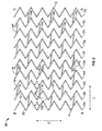
- each of the stents 30, 40, 50 and 60 are illustrated in planar views.
- planar views are depicted for ease of illustration and that the stents depicted are tubular with lines A-A and B-B forming division lines along the longitudinal axis L' of the stents in order to illustrate the stent geometry in a planar view.
- stent 30 is comprised of a plurality of circumferential expansion members 12 and a plurality of interconnecting members 14.
- Each of the plurality of interconnecting members 14 joins adjacent pairs of circumferential expansion members 14.
- Each interconnecting member 14 forms a junction with a strut 16 of each of the adjacent circumferential expansion members 12 and intersects the strut 16 at approximately a mid-point along the length of each strut 16.
- the plurality of interconnecting members 14 form groupings 14a, 14b, 14c, 14d, 14e and 14f along the longitudinal axis L' of the stent 30.
- each of the interconnecting members 14 lie in the folding planes of the peaks 12p and troughs 12t and struts 16 about angle ⁇ , it has been found desirable to offset each of the interconnecting members 14 from the a line parallel to the longitudinal axis L' of the stent 30 by an angle ⁇ in order to enhance the folding properties of the circumferential expansion members 12 from a larger diameter to a smaller diameter of the stent 30.
- each of the plurality of interconnecting members 14 in groupings 14a-14f have the same offset angle ⁇ and all of the plurality of interconnecting members 14 are parallel to each other.
- first strain relief section 18 has a generally C-shaped configuration that has a right-handed or clockwise orientation
- second strain relief section 20 also having a generally C-shaped configuration has a generally left-handed or counterclockwise orientation.
- peaks 12p or troughs 12t there are six peaks 12p and six peaks 12t in each of the plurality of circumferential expansion elements 12 and three interconnecting members 14 interconnect each pair of adjacent circumferential expansion elements 12.
- the interconnecting members 14 are circumferentially offset one peak 12p and one trough 12t from the interconnecting members 14 in an adjacent pair of circumferential expansion elements 12.
- interconnecting elements in groups 14a, 14c and 14e interconnect circumferential expansion element pairs 12a-12b, 12c-12d, 12e-12f, 12g-12h and 12i-12j
- interconnecting elements in groups 14b, 14d and 14f interconnect circumferential expansion element pairs 12b-12c, 12d-12f, 12f-12g, 12g-12h.
- the interconnecting elements in group 14a, 14c and 14e each being offset by one peak 12p and one trough 12t along the circumferential axis of each circumferential expansion element 12.
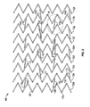
- stent 40 is illustrated and has a substantially identical configuration of circumferential expansion elements 12 and interconnecting elements 14, except that instead of employing a 2:1 ratio of peaks 12p or trough's 12t to interconnecting elements, stent 40 employs a 3:1 ratio, such that each circumferential expansion element 12a-12i has six peaks 12p and six troughs 12t, but adjacent pairs of circumferential elements 12 are interconnected by only two interconnecting elements 14.
- the interconnecting elements of a first circumferential expansion element pair are circumferentially offset from the interconnecting elements of a second adjacent circumferential expansion element pair, except in stent 40, the offset is either one peak 12p and two troughs 12t or two peaks 12p and one trough 12t.
- the offset is either one peak 12p and two troughs 12t or two peaks 12p and one trough 12t.
- Interconnecting element groups 14a and 14c interconnects circumferential expansion element pairs 12b-12c, 12d-12e, 12f-12g and 12h-12i, and interconnecting element groups 14b and 14d interconnect circumferential expansion element pairs 12a-12b, 12c-12d, 12e-12f and 12g-12h.
- each of the interconnecting elements 14 are also angularly offset from the longitudinal axis of the stent by an angle ⁇ , except that the plurality of interconnecting elements 14 are not all parallel relative to each other. Rather, the interconnecting elements in interconnecting element groups 14a and 14c are parallel to each other and the interconnecting elements in interconnecting elements groups 14b and 14d are parallel to each other, with the interconnecting elements in groups 14a and 14c being offset from the longitudinal axis of the stent by an angle ⁇ - which is alternate to the angle ⁇ , also denoted angle ⁇ +, forming the offset from the longitudinal axis L' for the interconnecting elements in groups 14b and 14d.
- angle ⁇ + and angle ⁇ - is intended to denote that these angles represent the substantially the same angular offset from the longitudinal axis L', but have alternate orientations relative to the circumferential axis of the stent 40.
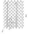
- stent 50 shares the common elements of circumferential expansion elements 12, having a plurality of peaks 12p and troughs 12t interconnecting a plurality of struts 16, and U-shaped sections 22, and interconnecting elements 14.
- the plurality of interconnecting elements 14 form two groups of interconnecting elements 14a and interconnecting elements 14b.
- Each of the individual interconnecting elements 14 in interconnecting element groups 14a and 14b are also angularly offset from the longitudinal axis L' of the stent 50 by angle ⁇ .
- each of the plurality of individual interconnecting elements 14 are generally aligned along a common longitudinal axis. In this manner, with the exception of the most proximal 12a and the most distal 12b circumferential ring elements, each of the plurality of interconnecting elements form a substantially four-point junction 19 at approximately a mid-point a strut 16 on each of circumferential expansion elements 12b-12h.
- the substantially four-point junction 19 is formed between a distal strain relief section 20 of one interconnecting member with a proximal side of a strut 16 and a proximal strain relief section 18 of an adjacent interconnecting element 14 with a distal side of the same strut 16.
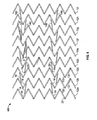
- stent 60 which, like stents 30, 40 and 50 is comprised of a plurality of circumferential expansion elements 12 and interconnecting elements 14 that interconnect adjacent pairs of circumferential expansion elements 12.
- stent 60 has groupings of interconnecting elements 14 into interconnecting element groups 14a, 14b, 14c and 14d.
- interconnecting element groups 14a and 14d interconnect identical pairs of circumferential expansion elements 12 and interconnecting element groups 14b and 14c interconnect identical pairs of circumferential expansion elements 12.
- each of the interconnecting elements in interconnecting element groups 14a and 14d are angularly offset from the longitudinal axis L' of the stent 60 by an angle ⁇ -and are parallel to one and other.
- each of the interconnecting elements in interconnecting element groups 14b and 14c are angularly offset from the longitudinal axis L' of the stent 60 by and angle ⁇ + and are parallel to one and other.
- the interconnecting elements 14 For each adjacent pair of circumferential expansion elements 12, the interconnecting elements 14 have different orientations of angular offset from the longitudinal axis L' of the stent 50.
- the interconnecting elements of group 14b and group 14c are offset by angle ⁇ + and by angle ⁇ -, respectively.
- the interconnecting elements of group 14a and 14d are offset by angle ⁇ - and by angle ⁇ +, respectively.
- the interconnecting elements are out of phase, in that they have different angular orientations of angle ⁇ .
- the interconnecting elements are circumferentially offset by a single peak 12p, with interconnecting element group 14a being circumferentially offset from interconnecting element group by a single peak 12p, and interconnecting element group 14c being circumferentially offset from interconnecting element group 14d by a single peak 12p.
- the circumferential offset between interconnecting element group pair 14b-14c is two peaks 12p and three troughs 12t, while the circumferential offset between interconnecting element group pair 14a-14d is four peaks 12p and three troughs 12t.
- stents 1, 20, 30, 40 and 50 describe various geometries all comprised of common structural elements, namely, circumferential expansion elements 12 having a plurality of peaks 12p and troughs 12t and struts 15 interconnected by hinge elements 22.
- circumferential expansion elements 12 having a plurality of peaks 12p and troughs 12t and struts 15 interconnected by hinge elements 22.
- variations on the number of and positioning of the interconnecting members 14 between adjacent pairs of circumferential expansion elements 12 and along the circumferential axis of the stent are also contemplated by the present invention and that the specific embodiments illustrated and described with reference to the figures is exemplary in nature.
- FIG 3 represents a stent 40.
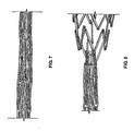
- Stent 40 was fabricated by laser-cutting the described geometry from a nickel-titanium hypotube. After laser cutting, the stent 40 was annealed to set shape memory properties for the stent 40 with a fully expanded, enlarged outer diameter of 5.8 mm and a length of 30.6 mm. Stent 40 was capable of being crimped to a smaller, crimped outer diameter of 1.4 mm and was placed within a constraining sheath as illustrated in Figure 7 . Stent 40 exhibited excellent crimpability with the struts 16 folding at the generally U-shaped hinge elements 22 through angle ⁇ without appreciable interference between the circumferential expansion elements 12 and the interconnecting elements 14.
- the stent 40 During radial expansion of the stent 40 from its first constrained smaller diameter, i.e ., 1.4 mm, to its second enlarged radially expanded diameter, i.e. , 5.8 mm, the stent 40 exhibited no foreshortening characteristic of many stent geometries known in the art. In contrast to foreshortening the stent 40 unexpectedly elongated by 2.5%. Heretofore a stent that elongates upon radial expansion is unknown in the art.
- Figure 8 depicts stent 40 radially expanding as it the constraining sheath is being withdrawn from the stent 40.
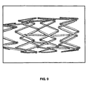
- Figure 9 depicts stent 40 in virtually its fully radially expanded enlarged diameter, with just a proximal section of the stent 40 be constrained in the constraining sheath (not pictured).
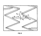
- Figure 6 is an enlarged section of the stent 40 illustrating the mid-strut connection between the circumferential expansion element 12 and the interconnecting element 14 at the proximal and distal strain relief sections 18 and 20, and clearly showing the generally U-shaped hinge elements 22 a the peaks 12p and troughs 12t of each circumferential expansion element 12.
- Figure 6 also clearly depicts the differences in the widths W t of the proximal and distal strain relief sections and the width W i of the body of the interconnecting member 14, as well as the difference between the width W h of the U-shaped hinge element 22 and the width W s of the strut 16.
- the plurality of circumferential expansion elements 12 and interconnecting members 14, and components sections thereof are preferably made of materials selected from the group consisting of titanium, vanadium, aluminum, nickel, tantalum, zirconium, chromium, silver, gold, silicon, magnesium, niobium, scandium, platinum, cobalt, palladium, manganese, molybdenum and alloys thereof, and nitinol and stainless steel.
- the plurality of circumferential expansion elements 12 and the plurality of interconnecting members 14 may be made of the same material or of different materials and have the same material properties or have different material properties.
- material properties is intended to encompass physical properties, including without limitation, elasticity, tensile strength, mechanical properties, hardness, bulk and/or surface grain size, grain composition, and grain boundary size, intra and inter-granular precipitates.
- materials selected for the plurality of circumferential expansion elements 12 aud the plurality of interconnecting members 14 may be selected to have the same or different chemical properties.
- chemical properties is intended to encompass both any chemical reaction and change of state that the material may undergo after being implanted into a body and the physiological response of the body to the material after implantation.
- inventive stents 10, 30, 40, 50 and 60 including each of their elements, namely the plurality of circumferential expansion elements 12 and interconnecting members 14 and component sections thereof, are preferably made of a bulk material having controlled heterogeneities on the luminal surface thereof.
- U.S. Patent Application Serial No. 09/754,304 filed December 22, 2000 which is a divisional of U.S. Patent No.
- 6,379,383 issued April 30,2002 heterogeneities are controlled by fabricating the bulk material of the stent to have defined grain sizes, chemical and intra- and intergranular precipitates and where the bulk and surface morphology differ, yielding areas or sites along the surface of the stent while maintaining acceptable or optimal protein binding capability.
- the characteristically desirable properties of the inventive stent are: (a) optimum mechanical properties consistent with or exceeding regulatory approval criteria, (b) minimization of defects, such as cracking or pin hole defects, (c) a fatigue life of 400 MM cycles as measured by simulated accelerated testing, (d) corrosion and/or corrosion-fatigue resistance, (e) biocompatibility without having biologically significant impurities in the material, (f) a substantially non-frictional abluminal surface to facilitate atraumatic vascular crossing and tracking and compatible with transcatheter techniques for stent introduction, (g) radiopaque at selected sites and MRI compatible, (h) have a luminal surface which is optimized for surface energy and microtopography, (i) minimal manufacturing and material cost consistent with achieving the desired material properties, and (j) high process yields.
- the foregoing properties are achieved by fabricating a stent by the same metal deposition methodologies as are used and standard in the microelectronics and nano-fabrication vacuum coating arts.
- the preferred deposition methodologies include ion-beam assisted evaporative deposition and sputtering techniques.
- ion beam-assisted evaporative deposition it is preferable to employ dual and simultaneous thermal electron beam evaporation with simultaneous ion bombardment of the substrate using an inert gas, such as argon, xenon, nitrogen or neon.
- Bombardment with an inert gas, such as argon ions serves to reduce void content by increasing the atomic packing density in the deposited material during deposition.
- the reduced void content in the deposited material allows the mechanical properties of that deposited material to be similar to the bulk material properties. Deposition rates up to 20 nm/sec are achievable using ion beam-assisted evaporative deposition techniques.
- a 200-micron thick stainless steel film may be deposited within about four hours of deposition time.
- a cylindrical sputtering target a single circumferential source that concentrically surrounds the substrate that is held in a coaxial position within the source.
- Alternate deposition processes which may be employed to form the stent in accordance with the present invention are cathodic arc, laser ablation, and direct ion beam deposition.
- the crystalline structure of the deposited film affects the mechanical properties of the deposited film. These mechanical properties of the deposited film may be modified by post-process treatment, such as by, for example, annealing, highpressure treatment or gas quenching.
- Materials to make the inventive stents are chosen for their biocompatibility, mechanical properties, i.e ., tensile strength, yield strength, and their ease of deposition include the following: elemental titanium, vanadium, aluminum, nickel, tantalum, zirconium, chromium, silver, gold, silicon, magnesium, niobium, scandium, platinum, cobalt, palladium, manganese, molybdenum and alloys thereof, such as zirconium-titanium-tantalum alloys, nitinol, and stainless steel.
- the chamber pressure, the deposition pressure and the partial pressure of the process gases are controlled to optimize deposition of the desired species onto the substrate.
- both the reactive and non-reactive gases are controlled and the inert or non-reactive gaseous species introduced into the deposition chamber are typically argon and nitrogen.
- the substrate may be either stationary or moveable, either rotated about its longitudinal axis, or moved in an X-Y plane within the reactor to facilitate deposition or patterning of the deposited material onto the substrate.
- the deposited material maybe deposited either as a uniform solid film onto the substrate, or patterned by (a) imparting either a positive or negative pattern onto the substrate, such as by etching or photolithography techniques applied to the substrate surface to create a positive or negative image of the desired pattern or (b) using a mask or set of masks which are either stationary or moveable relative to the substrate to define the pattern applied to the substrate.
- Patterning may be employed to achieve complex finished geometries of the resultant stent, both in the context of spatial orientation of the pattern as well as the material thickness at different regions of the deposited film, such as by varying the wall thickness of the material over its length to thicken sections at proximal and distal ends of the stent to prevent flaring of the stent ends upon radial expansion of the stent.
- the stent may be removed from the substrate after stent formation by any of a variety of methods.
- the substrate may be removed by chemical means, such as etching or dissolution, by ablation, by machining or by ultrasonic energy.
- a sacrificial layer of a material such as carbon or aluminum, may be deposited intermediate the substrate and the stent and the sacrificial layer removed by melting, chemical means, ablation, machining or other suitable means to free the stent from the substrate.
- the resulting stent may then be subjected to post-deposition processing to modify the crystalline structure, such as by annealing, or to modify the surface topography, such as by etching to affect and control the heterogeneities on the blood flow surface of the stent.
- a plurality of microgrooves may be imparted onto the luminal and/or abluminal surface of the stent 10, as is more fully described in International Publication No. WO 99/23977, published 20 May 1999 , which is commonly assigned with the present application.
- the plurality of microgrooves may be formed either as a post-deposition process step, such as by etching, or during deposition, such as by depositing the stent-forming material onto a mandrel which has a microtopography on the surface thereof which causes the metal to deposit with the microgroove pattern as part of the deposited material.
- Each of the preferred embodiments of the present invention are fabricated by employing a vapor deposition technique which entails vapor depositing a stent-forming metal onto a substrate.
- the substrate may be planar or cylindrical and is either pre-pattemed with one of the preferred geometries of first and interconnecting members, in either positive or negative image, or the substrate may be un-patterned. Where the substrate is un-patterned, the deposited stent-forming metal is subjected to post-deposition patterning to pattern the deposited stent-forming metal into one of the preferred geometries of the first and interconnecting members.
- the need for post-deposition processing of the patterned endoluminal stent e.g ., modifying the surface of the stent by mechanical, electrical, thermal or chemical machining or polishing, is eliminated or minimized.
- Vapor deposition fabrication of the inventive endoluminal stents offers many advantages, including, for example, the ability to fabricate stents of complex geometries, ultrafine dimensional tolerances on the order of Angstroms, the ability to control fatigue life, corrosion resistance, corrosion fatigue, inter- and intra-granular precipitates and their effect on corrosion resistance and corrosion fatigue, bulk material composition, bulk and surface material properties, radioopacity, and the ability to vary the transverse profiles, Z-axis thickness and X-Y-axis surface area of the stent structural elements in manners that affect the longitudinal flexibility, hoop strength, and radial expansion behavior and profile of the stent.
- Bulk material composition may be adjusted to employ elemental fractions in alloy compositions that are not feasible when using conventionally formed metals.
- nickel-titanium tubes exhibiting shape memory and/or superelastic properties were made employing in excess of 51.5 atomic percent nickel, which is not achievable using conventional working techniques due to high plateau stresses exhibited by the material.
- the present inventors have fabricated nickel-titanium alloy tubes employing the method of the present invention that contain between 51.5 and 55 atomic percent nickel.
- Vapor deposition of the inventive endoluminal stent significantly reduces or virtually eliminates inter- and intra-granular precipitates in the bulk material. It is common practice in the nickel-titanium endoluminal device industry to control transition temperatures and resulting mechanical properties by altering local granular nickel-titanium ratios by precipitation regimens. In the present invention, the need to control precipitates for mechanical properties is eliminated. Where nickel-titanium is employed as the stent-forming metal in the present invention, local nickel-titanium ratios will be the same or virtually identical to the nickel-titanium ratios in the bulk material, while still allowing for optimal morphology and eliminating the need for employing precipitation heat treatment. The resulting deposited stent-forming metal exhibits superior corrosion resistance, and hence, resistance to corrosion fatigue, when compared to conventional wrought nickel-titanium alloys.
- the plurality of circumferential expansion elements 12 and the plurality of interconnecting members 14 may be conformationally configured during vapor deposition to impart a generally rectangular, ovular or elliptical transverse cross-sectional profile with either right angled edges or with chamfered or curved leading and trailing luminal and abluminal surface edges in the longitudinal axis of the stent in order to provide better blood flow surface profiles.
Claims (11)
- Endoluminaler Stent (10), der Folgendes umfasst:a. eine Vielzahl von Umfangserweiterungselementen (12), die koaxial beabstandet sind, um eine röhrenförmige Form auszubilden, und jeweils eine wellenartige Struktur von Spitzen (12p) und Tälern (12t) aufweisen, die durch Verstrebungen (16) verbunden sind, wobei die Verstrebungen lineare Abschnitte bilden und an den Spitzen und Tälern durch Gelenkselemente (22) verbunden sind, die eine geringere Breite als die Verstrebungen (16) aufweisen; undb. eine Vielzahl linearer Verbindungselemente (14), die benachbarte Paare von Umfangserweiterungselementen (12) verbinden und etwa an den Mittelpunkten benachbarter Verstrebungen (16) entlang einer Längsachse des endoluminalen Stents verbunden sind, wobei die Verbindungselemente (14) krummlinige erste und zweite Endabschnitte aufweisen, wobei jeder Abschnitt der ersten und zweiten Endabschnitte eine geringere Breite als die Verbindungselemente aufweist;c. dadurch gekennzeichnet, dass zumindest eines von der Vielzahl der Umfangserweiterungselemente (12) und von der Vielzahl linearer Verbindungselemente (14) aus einer Nickel-Titan-Formgedächtnislegierung besteht, die einen Überschuss von 51,5 Atomprozent Nickel umfasst, und dadurch, dass der Stent durch ein Dampfabscheidungsverfahren hergestellt wird.
- Endoluminaler Stent nach Anspruch 1, worin jedes Element von der Vielzahl der Umfangserweiterungselemente (12) ferner eine Zick-Zack-Form entlang einer Umfangsachse des endoluminalen Stents umfasst, wobei die Verstrebungen (16) im gesamten Abschnitt der Verstrebungen eine einheitliche Breite aufweisen.
- Endoluminaler Stent nach Anspruch 1, worin die krummlinigen ersten und zweiten Endabschnitte an entgegengesetzten Enden jedes Verbindungselements (14), das eine Verbindung mit den Verstrebungen (16) herstellt, angeordnet sind.
- Endoluminaler Stent nach Anspruch 3, worin jedes der Vielzahl an Umfangserweiterungselementen (12) mit jedem der Vielzahl an Verbindungselementen (14) einstückig und monolithisch ausgebildet ist.
- Endoluminaler Stent nach Anspruch 4, worin die krummlinigen ersten und zweiten Endabschnitte der Vielzahl an linearen Verbindungselementen (14) ferner C-förmige Abschnitte umfassen.
- Endoluminaler Stent nach Anspruch 1, worin die Vielzahl linearer Verbindungselemente (14) alle parallel zueinander stehen.
- Endoluminaler Stent nach Anspruch 1, worin die Vielzahl linearer Verbindungselemente (14) entlang einer Längsachse des endoluminalen Stents in zumindest zwei Gruppen von Verbindungselementen gruppiert sind, wobei eine erste der zumindest zwei Gruppen in Bezug auf die Längsachse des endoluminalen Stents eine andere Winkelausrichtung als eine zweite der zumindest zwei Gruppen aufweist.
- Endoluminaler Stent nach Anspruch 1, worin sich der endoluminale Stent entlang der Längsachse des endoluminalen Stents verlängert, wenn er sich von einem kleineren Durchmesser auf einen größeren Durchmesse erweitet.
- Endoluminaler Stent nach Anspruch 1, worin
die Verstrebungen (16) entlang einer Umfangsachse des endoluminalen Stents im Allgemeinen eine Zick-Zack-Form bilden und an den Spitzen und Tälern durch Gelenkselemente (22) mit einer geringeren Breite als die Verstrebungen verbunden sind und worin
die krummlinigen ersten und zweiten Endabschnitte an entgegengesetzten Enden jedes der Verbindungselemente (14) vorliegen, die eine Verbindung zu den Verstrebungen herstellen, wobei jeder der krummlinigen ersten und zweiten Eng-Abschnitte der linearen Verbindungselemente ferner im Allgemeinen C-förmige Abschnitte mit einer geringeren Breite als der Rest des Verbindungselements umfasst, und worin
jedes der Umfangserweiterungselemente (12) mit jedem der Vielzahl an Verbindungselementen einstückig und monolithisch ausgebildet ist. - Endoluminaler Stent nach Anspruch 1, worin die linearen Verbindungselemente (14) etwa an den Mittelpunkten benachbarter Verstrebungen (16) entlang einer Längsachse des endoluminalen Stents durch Zugentlastungsabschnitte (18, 20) verbunden sind, wobei die Zugentlastungsabschnitte eine geringere Breite als jene der Verbindungselemente aufweisen.
- Endoluminaler Stent nach Anspruch 1, worin zumindest eines aus der Vielzahl der Umfangserweiterungselemente (12) und der Veilzahl linearer Verbindungselemente (14) aus einer Nickel-Titan-Formgedächtnislegierung besteht, die zwischen etwa 51,5 und etwa 55 Atomprozent Nickel umfasst.
Priority Applications (1)
| Application Number | Priority Date | Filing Date | Title |
|---|---|---|---|
| EP10185232.5A EP2289464B1 (de) | 2003-03-19 | 2004-03-18 | Endoluminaler Stent mit mittigen Verbindungselementen |
Applications Claiming Priority (2)
| Application Number | Priority Date | Filing Date | Title |
|---|---|---|---|
| US45578303P | 2003-03-19 | 2003-03-19 | |
| PCT/US2004/008247 WO2004084764A2 (en) | 2003-03-19 | 2004-03-18 | Endoluminal stent having mid-interconnecting members |
Related Child Applications (2)
| Application Number | Title | Priority Date | Filing Date |
|---|---|---|---|
| EP10185232.5A Division EP2289464B1 (de) | 2003-03-19 | 2004-03-18 | Endoluminaler Stent mit mittigen Verbindungselementen |
| EP10185232.5 Division-Into | 2010-10-01 |
Publications (3)
| Publication Number | Publication Date |
|---|---|
| EP1610724A2 EP1610724A2 (de) | 2006-01-04 |
| EP1610724A4 EP1610724A4 (de) | 2007-06-13 |
| EP1610724B1 true EP1610724B1 (de) | 2010-12-22 |
Family
ID=34572701
Family Applications (2)
| Application Number | Title | Priority Date | Filing Date |
|---|---|---|---|
| EP04757798A Expired - Lifetime EP1610724B1 (de) | 2003-03-19 | 2004-03-18 | Endoluminaler stent mit mittelverbindungsgliedern |
| EP10185232.5A Expired - Lifetime EP2289464B1 (de) | 2003-03-19 | 2004-03-18 | Endoluminaler Stent mit mittigen Verbindungselementen |
Family Applications After (1)
| Application Number | Title | Priority Date | Filing Date |
|---|---|---|---|
| EP10185232.5A Expired - Lifetime EP2289464B1 (de) | 2003-03-19 | 2004-03-18 | Endoluminaler Stent mit mittigen Verbindungselementen |
Country Status (10)
| Country | Link |
|---|---|
| US (2) | US7122049B2 (de) |
| EP (2) | EP1610724B1 (de) |
| JP (1) | JP5021298B2 (de) |
| CN (1) | CN100558320C (de) |
| AT (1) | ATE492246T1 (de) |
| AU (1) | AU2004224415B2 (de) |
| CA (1) | CA2519226C (de) |
| DE (1) | DE602004030671D1 (de) |
| MX (1) | MXPA05009823A (de) |
| WO (1) | WO2004084764A2 (de) |
Families Citing this family (41)
| Publication number | Priority date | Publication date | Assignee | Title |
|---|---|---|---|---|
| US6261319B1 (en) | 1998-07-08 | 2001-07-17 | Scimed Life Systems, Inc. | Stent |
| US7736687B2 (en) | 2006-01-31 | 2010-06-15 | Advance Bio Prosthetic Surfaces, Ltd. | Methods of making medical devices |
| US6923829B2 (en) | 2002-11-25 | 2005-08-02 | Advanced Bio Prosthetic Surfaces, Ltd. | Implantable expandable medical devices having regions of differential mechanical properties and methods of making same |
| US20080220039A1 (en) * | 2004-09-17 | 2008-09-11 | Sherman Darren R | Thin Film Medical Devices Manufactured on Application Specific Core Shapes |
| US7344560B2 (en) * | 2004-10-08 | 2008-03-18 | Boston Scientific Scimed, Inc. | Medical devices and methods of making the same |
| US20070213810A1 (en) * | 2005-03-14 | 2007-09-13 | Richard Newhauser | Segmented endoprosthesis |
| US20070255094A1 (en) * | 2005-03-14 | 2007-11-01 | Oepen Randolf V | Crack/fatigue resistant endoprosthesis |
| US7837726B2 (en) * | 2005-03-14 | 2010-11-23 | Abbott Laboratories | Visible endoprosthesis |
| US20070061003A1 (en) * | 2005-09-15 | 2007-03-15 | Cappella, Inc. | Segmented ostial protection device |
| US20070088428A1 (en) * | 2005-09-15 | 2007-04-19 | Cappella, Inc. | Intraluminal device with asymmetric cap portion |
| US20100010622A1 (en) * | 2006-03-13 | 2010-01-14 | Abbott Laboratories | Hybrid segmented endoprosthesis |
| US20080097620A1 (en) | 2006-05-26 | 2008-04-24 | Nanyang Technological University | Implantable article, method of forming same and method for reducing thrombogenicity |
| WO2008036870A2 (en) * | 2006-09-21 | 2008-03-27 | Cleveny Technologies | A specially configured and surface modified medical device with certain design features that utilize the intrinsic properties of tungsten, zirconium, tantalum and/or niobium |
| US8974514B2 (en) | 2007-03-13 | 2015-03-10 | Abbott Cardiovascular Systems Inc. | Intravascular stent with integrated link and ring strut |
| US8926689B2 (en) * | 2007-06-22 | 2015-01-06 | C. R. Bard, Inc. | Flexible stent with hinged connectors |
| US20090210049A1 (en) * | 2008-02-15 | 2009-08-20 | Joseph Michael Thielen | Peripheral overlap stent |
| US9173983B2 (en) * | 2008-04-08 | 2015-11-03 | Cook Medical Technologies Llc | Surface structure of a component of a medical device and a method of forming the surface structure |
| US10898620B2 (en) | 2008-06-20 | 2021-01-26 | Razmodics Llc | Composite stent having multi-axial flexibility and method of manufacture thereof |
| US8206636B2 (en) | 2008-06-20 | 2012-06-26 | Amaranth Medical Pte. | Stent fabrication via tubular casting processes |
| US8206635B2 (en) | 2008-06-20 | 2012-06-26 | Amaranth Medical Pte. | Stent fabrication via tubular casting processes |
| WO2011056981A2 (en) | 2009-11-04 | 2011-05-12 | Nitinol Devices And Components, Inc. | Alternating circumferential bridge stent design and methods for use thereof |
| EP3795119A1 (de) * | 2010-05-10 | 2021-03-24 | Edwards Lifesciences Corporation | Herzklappenprothese mit zusammenklappbarem rahmen und freitragenden kommissurenabschnitten |
| US9301864B2 (en) | 2010-06-08 | 2016-04-05 | Veniti, Inc. | Bi-directional stent delivery system |
| US8864811B2 (en) | 2010-06-08 | 2014-10-21 | Veniti, Inc. | Bi-directional stent delivery system |
| US9233014B2 (en) | 2010-09-24 | 2016-01-12 | Veniti, Inc. | Stent with support braces |
| WO2012047308A1 (en) | 2010-10-08 | 2012-04-12 | Nitinol Devices And Components, Inc. | Alternating circumferential bridge stent design and methods for use thereof |
| CN102743245A (zh) * | 2011-04-22 | 2012-10-24 | 陈启星 | 撑开式管状血管支架 |
| US8728563B2 (en) * | 2011-05-03 | 2014-05-20 | Palmaz Scientific, Inc. | Endoluminal implantable surfaces, stents, and grafts and method of making same |
| US20130035753A1 (en) * | 2011-08-01 | 2013-02-07 | Abbott Cardiovascular Systems Inc. | Multiple Scaffold Design And Coating Thereof |
| NZ701992A (en) | 2012-05-14 | 2016-03-31 | Bard Inc C R | Uniformly expandable stent |
| US8834556B2 (en) * | 2012-08-13 | 2014-09-16 | Abbott Cardiovascular Systems Inc. | Segmented scaffold designs |
| US9956097B2 (en) * | 2012-10-23 | 2018-05-01 | Abbott Cardiovascular Systems Inc. | Methods for vascular restoration therapy |
| USD723165S1 (en) | 2013-03-12 | 2015-02-24 | C. R. Bard, Inc. | Stent |
| CN117796970A (zh) | 2013-03-13 | 2024-04-02 | 爱德华兹生命科学卡迪尔克有限责任公司 | 铰接式连合瓣膜支架和方法 |
| US10271975B2 (en) | 2013-03-15 | 2019-04-30 | Atrium Medical Corporation | Stent device having reduced foreshortening and recoil and method of making same |
| CN105451691B (zh) | 2013-06-21 | 2018-07-17 | 波士顿科学国际有限公司 | 具有偏转连接器的支架 |
| US10722389B2 (en) | 2015-01-07 | 2020-07-28 | Sahajanand Medical Technologies Private Limited | Endoluminal stent |
| AU2016344149B2 (en) * | 2015-10-27 | 2020-09-03 | Contego Medical, Inc. | Transluminal angioplasty devices and methods of use |
| JP2019076121A (ja) * | 2016-03-18 | 2019-05-23 | テルモ株式会社 | ステント |
| US10603165B2 (en) * | 2016-12-06 | 2020-03-31 | Edwards Lifesciences Corporation | Mechanically expanding heart valve and delivery apparatus therefor |
| CN109091275B (zh) * | 2018-08-24 | 2024-01-30 | 四川大学 | 生物可降解支架 |
Family Cites Families (72)
| Publication number | Priority date | Publication date | Assignee | Title |
|---|---|---|---|---|
| US4733665C2 (en) | 1985-11-07 | 2002-01-29 | Expandable Grafts Partnership | Expandable intraluminal graft and method and apparatus for implanting an expandable intraluminal graft |
| CA2380683C (en) | 1991-10-28 | 2006-08-08 | Advanced Cardiovascular Systems, Inc. | Expandable stents and method for making same |
| US6336938B1 (en) | 1992-08-06 | 2002-01-08 | William Cook Europe A/S | Implantable self expanding prosthetic device |
| JP2703510B2 (ja) | 1993-12-28 | 1998-01-26 | アドヴァンスド カーディオヴァスキュラー システムズ インコーポレーテッド | 拡大可能なステント及びその製造方法 |
| US5733303A (en) | 1994-03-17 | 1998-03-31 | Medinol Ltd. | Flexible expandable stent |
| US5843120A (en) | 1994-03-17 | 1998-12-01 | Medinol Ltd. | Flexible-expandable stent |
| US6165210A (en) | 1994-04-01 | 2000-12-26 | Gore Enterprise Holdings, Inc. | Self-expandable helical intravascular stent and stent-graft |
| US20020156523A1 (en) | 1994-08-31 | 2002-10-24 | Lilip Lau | Exterior supported self-expanding stent-graft |
| US6015429A (en) | 1994-09-08 | 2000-01-18 | Gore Enterprise Holdings, Inc. | Procedures for introducing stents and stent-grafts |
| AU3783195A (en) | 1994-11-15 | 1996-05-23 | Advanced Cardiovascular Systems Inc. | Intraluminal stent for attaching a graft |
| CA2301351C (en) | 1994-11-28 | 2002-01-22 | Advanced Cardiovascular Systems, Inc. | Method and apparatus for direct laser cutting of metal stents |
| US6896696B2 (en) | 1998-11-20 | 2005-05-24 | Scimed Life Systems, Inc. | Flexible and expandable stent |
| DE69637527D1 (de) | 1995-03-01 | 2008-06-26 | Boston Scient Scimed Inc | Längsflexibler und expandierbarer stent |
| US6124523A (en) | 1995-03-10 | 2000-09-26 | Impra, Inc. | Encapsulated stent |
| US6059810A (en) | 1995-05-10 | 2000-05-09 | Scimed Life Systems, Inc. | Endovascular stent and method |
| US5776161A (en) * | 1995-10-16 | 1998-07-07 | Instent, Inc. | Medical stents, apparatus and method for making same |
| US5938682A (en) | 1996-01-26 | 1999-08-17 | Cordis Corporation | Axially flexible stent |
| US5772864A (en) | 1996-02-23 | 1998-06-30 | Meadox Medicals, Inc. | Method for manufacturing implantable medical devices |
| US6334871B1 (en) | 1996-03-13 | 2002-01-01 | Medtronic, Inc. | Radiopaque stent markers |
| FR2747301B1 (fr) | 1996-04-10 | 1998-09-18 | Nycomed Lab Sa | Dispositif implantable destine a maintenir ou retablir la section normale de passage d'un conduit corporel, ainsi qu'un systeme pour sa mise en place |
| US5807404A (en) | 1996-09-19 | 1998-09-15 | Medinol Ltd. | Stent with variable features to optimize support and method of making such stent |
| US6325826B1 (en) | 1998-01-14 | 2001-12-04 | Advanced Stent Technologies, Inc. | Extendible stent apparatus |
| WO1998020810A1 (en) | 1996-11-12 | 1998-05-22 | Medtronic, Inc. | Flexible, radially expansible luminal prostheses |
| US5868782A (en) | 1996-12-24 | 1999-02-09 | Global Therapeutics, Inc. | Radially expandable axially non-contracting surgical stent |
| US5827321A (en) | 1997-02-07 | 1998-10-27 | Cornerstone Devices, Inc. | Non-Foreshortening intraluminal prosthesis |
| US5853419A (en) | 1997-03-17 | 1998-12-29 | Surface Genesis, Inc. | Stent |
| US5817126A (en) | 1997-03-17 | 1998-10-06 | Surface Genesis, Inc. | Compound stent |
| US6033433A (en) | 1997-04-25 | 2000-03-07 | Scimed Life Systems, Inc. | Stent configurations including spirals |
| IT1292295B1 (it) | 1997-04-29 | 1999-01-29 | Sorin Biomedica Cardio Spa | Stent per angioplastica |
| US6451049B2 (en) | 1998-04-29 | 2002-09-17 | Sorin Biomedica Cardio, S.P.A. | Stents for angioplasty |
| US5741327A (en) | 1997-05-06 | 1998-04-21 | Global Therapeutics, Inc. | Surgical stent featuring radiopaque markers |
| US6070589A (en) * | 1997-08-01 | 2000-06-06 | Teramed, Inc. | Methods for deploying bypass graft stents |
| US6309414B1 (en) | 1997-11-04 | 2001-10-30 | Sorin Biomedica Cardio S.P.A. | Angioplasty stents |
| US6129755A (en) | 1998-01-09 | 2000-10-10 | Nitinol Development Corporation | Intravascular stent having an improved strut configuration |
| US6533807B2 (en) * | 1998-02-05 | 2003-03-18 | Medtronic, Inc. | Radially-expandable stent and delivery system |
| US6077296A (en) | 1998-03-04 | 2000-06-20 | Endologix, Inc. | Endoluminal vascular prosthesis |
| US6103320A (en) | 1998-03-05 | 2000-08-15 | Shincron Co., Ltd. | Method for forming a thin film of a metal compound by vacuum deposition |
| FR2777771B1 (fr) | 1998-04-27 | 2000-08-25 | Microval | Endoprothese vasculaire tubulaire et flexible |
| US6066169A (en) * | 1998-06-02 | 2000-05-23 | Ave Connaught | Expandable stent having articulated connecting rods |
| US6203732B1 (en) * | 1998-07-02 | 2001-03-20 | Intra Therapeutics, Inc. | Method for manufacturing intraluminal device |
| DE19829702C1 (de) * | 1998-07-03 | 2000-03-16 | Heraeus Gmbh W C | Radial aufweitbare Stützvorrichtung V |
| US6261319B1 (en) * | 1998-07-08 | 2001-07-17 | Scimed Life Systems, Inc. | Stent |
| US6461380B1 (en) * | 1998-07-28 | 2002-10-08 | Advanced Cardiovascular Systems, Inc. | Stent configuration |
| US6042597A (en) | 1998-10-23 | 2000-03-28 | Scimed Life Systems, Inc. | Helical stent design |
| US6063101A (en) | 1998-11-20 | 2000-05-16 | Precision Vascular Systems, Inc. | Stent apparatus and method |
| US6120847A (en) | 1999-01-08 | 2000-09-19 | Scimed Life Systems, Inc. | Surface treatment method for stent coating |
| US6325825B1 (en) | 1999-04-08 | 2001-12-04 | Cordis Corporation | Stent with variable wall thickness |
| US6730116B1 (en) * | 1999-04-16 | 2004-05-04 | Medtronic, Inc. | Medical device for intraluminal endovascular stenting |
| US6273911B1 (en) | 1999-04-22 | 2001-08-14 | Advanced Cardiovascular Systems, Inc. | Variable strength stent |
| US6245101B1 (en) * | 1999-05-03 | 2001-06-12 | William J. Drasler | Intravascular hinge stent |
| US6375676B1 (en) | 1999-05-17 | 2002-04-23 | Advanced Cardiovascular Systems, Inc. | Self-expanding stent with enhanced delivery precision and stent delivery system |
| US6540774B1 (en) * | 1999-08-31 | 2003-04-01 | Advanced Cardiovascular Systems, Inc. | Stent design with end rings having enhanced strength and radiopacity |
| US20010047200A1 (en) | 1999-10-13 | 2001-11-29 | Raymond Sun | Non-foreshortening intraluminal prosthesis |
| US6387123B1 (en) | 1999-10-13 | 2002-05-14 | Advanced Cardiovascular Systems, Inc. | Stent with radiopaque core |
| US6537311B1 (en) | 1999-12-30 | 2003-03-25 | Advanced Cardiovascular Systems, Inc. | Stent designs for use in peripheral vessels |
| US6355058B1 (en) | 1999-12-30 | 2002-03-12 | Advanced Cardiovascular Systems, Inc. | Stent with radiopaque coating consisting of particles in a binder |
| US6312463B1 (en) | 2000-02-01 | 2001-11-06 | Endotex Interventional Systems, Inc. | Micro-porous mesh stent with hybrid structure |
| EP1132058A1 (de) | 2000-03-06 | 2001-09-12 | Advanced Laser Applications Holding S.A. | Intravaskuläre Prothese |
| US6699278B2 (en) | 2000-09-22 | 2004-03-02 | Cordis Corporation | Stent with optimal strength and radiopacity characteristics |
| DE60136868D1 (de) | 2000-09-23 | 2009-01-15 | Boston Scient Scimed Inc | Intravaskulärer Stent |
| DE10050971A1 (de) | 2000-10-10 | 2002-04-11 | Biotronik Mess & Therapieg | Stent |
| US6485508B1 (en) | 2000-10-13 | 2002-11-26 | Mcguinness Colm P. | Low profile stent |
| AU2002233936A1 (en) | 2000-11-07 | 2002-05-21 | Advanced Bio Prosthetic Surfaces, Ltd. | Endoluminal stent, self-fupporting endoluminal graft and methods of making same |
| US6506211B1 (en) | 2000-11-13 | 2003-01-14 | Scimed Life Systems, Inc. | Stent designs |
| EP1212986A1 (de) * | 2000-12-08 | 2002-06-12 | SORIN BIOMEDICA CARDIO S.p.A. | Stent für Angioplastie und Herstellungsverfahren dafür |
| US7077859B2 (en) | 2000-12-22 | 2006-07-18 | Avantec Vascular Corporation | Apparatus and methods for variably controlled substance delivery from implanted prostheses |
| US6565599B1 (en) * | 2000-12-28 | 2003-05-20 | Advanced Cardiovascular Systems, Inc. | Hybrid stent |
| US6679911B2 (en) * | 2001-03-01 | 2004-01-20 | Cordis Corporation | Flexible stent |
| US6503272B2 (en) | 2001-03-21 | 2003-01-07 | Cordis Corporation | Stent-based venous valves |
| US6673106B2 (en) | 2001-06-14 | 2004-01-06 | Cordis Neurovascular, Inc. | Intravascular stent device |
| US6605110B2 (en) * | 2001-06-29 | 2003-08-12 | Advanced Cardiovascular Systems, Inc. | Stent with enhanced bendability and flexibility |
| US20040054399A1 (en) | 2002-09-17 | 2004-03-18 | Roth Noah M. | Anti-galvanic stent coating |
-
2004
- 2004-03-18 CN CNB2004800129661A patent/CN100558320C/zh not_active Expired - Lifetime
- 2004-03-18 MX MXPA05009823A patent/MXPA05009823A/es active IP Right Grant
- 2004-03-18 DE DE602004030671T patent/DE602004030671D1/de not_active Expired - Lifetime
- 2004-03-18 EP EP04757798A patent/EP1610724B1/de not_active Expired - Lifetime
- 2004-03-18 US US10/803,392 patent/US7122049B2/en active Active
- 2004-03-18 CA CA2519226A patent/CA2519226C/en not_active Expired - Lifetime
- 2004-03-18 EP EP10185232.5A patent/EP2289464B1/de not_active Expired - Lifetime
- 2004-03-18 WO PCT/US2004/008247 patent/WO2004084764A2/en active Application Filing
- 2004-03-18 AU AU2004224415A patent/AU2004224415B2/en not_active Expired
- 2004-03-18 JP JP2006507303A patent/JP5021298B2/ja not_active Expired - Lifetime
- 2004-03-18 AT AT04757798T patent/ATE492246T1/de not_active IP Right Cessation
-
2006
- 2006-10-13 US US11/549,493 patent/US7980289B2/en active Active
Also Published As
| Publication number | Publication date |
|---|---|
| EP1610724A2 (de) | 2006-01-04 |
| US7980289B2 (en) | 2011-07-19 |
| WO2004084764A2 (en) | 2004-10-07 |
| EP2289464B1 (de) | 2018-08-01 |
| CA2519226C (en) | 2013-01-15 |
| CA2519226A1 (en) | 2004-10-07 |
| US20070088430A1 (en) | 2007-04-19 |
| JP5021298B2 (ja) | 2012-09-05 |
| AU2004224415A1 (en) | 2004-10-07 |
| CN1787793A (zh) | 2006-06-14 |
| AU2004224415B2 (en) | 2011-07-14 |
| JP2006520648A (ja) | 2006-09-14 |
| MXPA05009823A (es) | 2006-03-13 |
| ATE492246T1 (de) | 2011-01-15 |
| US20040186554A1 (en) | 2004-09-23 |
| DE602004030671D1 (de) | 2011-02-03 |
| US7122049B2 (en) | 2006-10-17 |
| EP1610724A4 (de) | 2007-06-13 |
| CN100558320C (zh) | 2009-11-11 |
| WO2004084764A3 (en) | 2005-05-19 |
| EP2289464A1 (de) | 2011-03-02 |
Similar Documents
| Publication | Publication Date | Title |
|---|---|---|
| EP1610724B1 (de) | Endoluminaler stent mit mittelverbindungsgliedern | |
| US8641754B2 (en) | Endoluminal stent, self-supporting endoluminal graft and methods of making same | |
| US9707111B2 (en) | Stent with offset cell geometry | |
| US7625401B2 (en) | Endoprosthesis having foot extensions | |
| US8075610B2 (en) | Endoprosthesis for controlled contraction and expansion | |
| US8882826B2 (en) | Intravascular stent | |
| EP2529707B1 (de) | Endoprothese mit Fussverlängerungen | |
| US6451049B2 (en) | Stents for angioplasty | |
| US7625398B2 (en) | Endoprosthesis having foot extensions | |
| US20100241216A1 (en) | Stents for angioplasty | |
| CA2446863C (en) | Stent design | |
| US20100292777A1 (en) | Stent |
Legal Events
| Date | Code | Title | Description |
|---|---|---|---|
| PUAI | Public reference made under article 153(3) epc to a published international application that has entered the european phase |
Free format text: ORIGINAL CODE: 0009012 |
|
| 17P | Request for examination filed |
Effective date: 20051014 |
|
| AK | Designated contracting states |
Kind code of ref document: A2 Designated state(s): AT BE BG CH CY CZ DE DK EE ES FI FR GB GR HU IE IT LI LU MC NL PL PT RO SE SI SK TR |
|
| AX | Request for extension of the european patent |
Extension state: AL LT LV MK |
|
| DAX | Request for extension of the european patent (deleted) | ||
| A4 | Supplementary search report drawn up and despatched |
Effective date: 20070515 |
|
| RIN1 | Information on inventor provided before grant (corrected) |
Inventor name: ROSENBAUM, DAVID, G. Inventor name: BANAS, CHRISTOPHER, E. |
|
| 17Q | First examination report despatched |
Effective date: 20080313 |
|
| GRAP | Despatch of communication of intention to grant a patent |
Free format text: ORIGINAL CODE: EPIDOSNIGR1 |
|
| RIC1 | Information provided on ipc code assigned before grant |
Ipc: A61F 2/90 20060101AFI20100203BHEP |
|
| GRAS | Grant fee paid |
Free format text: ORIGINAL CODE: EPIDOSNIGR3 |
|
| GRAA | (expected) grant |
Free format text: ORIGINAL CODE: 0009210 |
|
| AK | Designated contracting states |
Kind code of ref document: B1 Designated state(s): AT BE BG CH CY CZ DE DK EE ES FI FR GB GR HU IE IT LI LU MC NL PL PT RO SE SI SK TR |
|
| REG | Reference to a national code |
Ref country code: GB Ref legal event code: FG4D |
|
| REG | Reference to a national code |
Ref country code: CH Ref legal event code: EP |
|
| REG | Reference to a national code |
Ref country code: IE Ref legal event code: FG4D |
|
| REF | Corresponds to: |
Ref document number: 602004030671 Country of ref document: DE Date of ref document: 20110203 Kind code of ref document: P |
|
| REG | Reference to a national code |
Ref country code: DE Ref legal event code: R096 Ref document number: 602004030671 Country of ref document: DE Effective date: 20110203 |
|
| REG | Reference to a national code |
Ref country code: NL Ref legal event code: VDEP Effective date: 20101222 |
|
| PG25 | Lapsed in a contracting state [announced via postgrant information from national office to epo] |
Ref country code: FI Free format text: LAPSE BECAUSE OF FAILURE TO SUBMIT A TRANSLATION OF THE DESCRIPTION OR TO PAY THE FEE WITHIN THE PRESCRIBED TIME-LIMIT Effective date: 20101222 Ref country code: SI Free format text: LAPSE BECAUSE OF FAILURE TO SUBMIT A TRANSLATION OF THE DESCRIPTION OR TO PAY THE FEE WITHIN THE PRESCRIBED TIME-LIMIT Effective date: 20101222 Ref country code: AT Free format text: LAPSE BECAUSE OF FAILURE TO SUBMIT A TRANSLATION OF THE DESCRIPTION OR TO PAY THE FEE WITHIN THE PRESCRIBED TIME-LIMIT Effective date: 20101222 Ref country code: CY Free format text: LAPSE BECAUSE OF FAILURE TO SUBMIT A TRANSLATION OF THE DESCRIPTION OR TO PAY THE FEE WITHIN THE PRESCRIBED TIME-LIMIT Effective date: 20101222 Ref country code: SE Free format text: LAPSE BECAUSE OF FAILURE TO SUBMIT A TRANSLATION OF THE DESCRIPTION OR TO PAY THE FEE WITHIN THE PRESCRIBED TIME-LIMIT Effective date: 20101222 Ref country code: BG Free format text: LAPSE BECAUSE OF FAILURE TO SUBMIT A TRANSLATION OF THE DESCRIPTION OR TO PAY THE FEE WITHIN THE PRESCRIBED TIME-LIMIT Effective date: 20110322 |
|
| PG25 | Lapsed in a contracting state [announced via postgrant information from national office to epo] |
Ref country code: ES Free format text: LAPSE BECAUSE OF FAILURE TO SUBMIT A TRANSLATION OF THE DESCRIPTION OR TO PAY THE FEE WITHIN THE PRESCRIBED TIME-LIMIT Effective date: 20110402 Ref country code: EE Free format text: LAPSE BECAUSE OF FAILURE TO SUBMIT A TRANSLATION OF THE DESCRIPTION OR TO PAY THE FEE WITHIN THE PRESCRIBED TIME-LIMIT Effective date: 20101222 Ref country code: GR Free format text: LAPSE BECAUSE OF FAILURE TO SUBMIT A TRANSLATION OF THE DESCRIPTION OR TO PAY THE FEE WITHIN THE PRESCRIBED TIME-LIMIT Effective date: 20110323 Ref country code: CZ Free format text: LAPSE BECAUSE OF FAILURE TO SUBMIT A TRANSLATION OF THE DESCRIPTION OR TO PAY THE FEE WITHIN THE PRESCRIBED TIME-LIMIT Effective date: 20101222 Ref country code: BE Free format text: LAPSE BECAUSE OF FAILURE TO SUBMIT A TRANSLATION OF THE DESCRIPTION OR TO PAY THE FEE WITHIN THE PRESCRIBED TIME-LIMIT Effective date: 20101222 Ref country code: PT Free format text: LAPSE BECAUSE OF FAILURE TO SUBMIT A TRANSLATION OF THE DESCRIPTION OR TO PAY THE FEE WITHIN THE PRESCRIBED TIME-LIMIT Effective date: 20110422 |
|
| PG25 | Lapsed in a contracting state [announced via postgrant information from national office to epo] |
Ref country code: RO Free format text: LAPSE BECAUSE OF FAILURE TO SUBMIT A TRANSLATION OF THE DESCRIPTION OR TO PAY THE FEE WITHIN THE PRESCRIBED TIME-LIMIT Effective date: 20101222 Ref country code: PL Free format text: LAPSE BECAUSE OF FAILURE TO SUBMIT A TRANSLATION OF THE DESCRIPTION OR TO PAY THE FEE WITHIN THE PRESCRIBED TIME-LIMIT Effective date: 20101222 Ref country code: SK Free format text: LAPSE BECAUSE OF FAILURE TO SUBMIT A TRANSLATION OF THE DESCRIPTION OR TO PAY THE FEE WITHIN THE PRESCRIBED TIME-LIMIT Effective date: 20101222 Ref country code: NL Free format text: LAPSE BECAUSE OF FAILURE TO SUBMIT A TRANSLATION OF THE DESCRIPTION OR TO PAY THE FEE WITHIN THE PRESCRIBED TIME-LIMIT Effective date: 20101222 |
|
| PLBE | No opposition filed within time limit |
Free format text: ORIGINAL CODE: 0009261 |
|
| STAA | Information on the status of an ep patent application or granted ep patent |
Free format text: STATUS: NO OPPOSITION FILED WITHIN TIME LIMIT |
|
| PG25 | Lapsed in a contracting state [announced via postgrant information from national office to epo] |
Ref country code: MC Free format text: LAPSE BECAUSE OF NON-PAYMENT OF DUE FEES Effective date: 20110331 Ref country code: DK Free format text: LAPSE BECAUSE OF FAILURE TO SUBMIT A TRANSLATION OF THE DESCRIPTION OR TO PAY THE FEE WITHIN THE PRESCRIBED TIME-LIMIT Effective date: 20101222 |
|
| REG | Reference to a national code |
Ref country code: CH Ref legal event code: PL |
|
| 26N | No opposition filed |
Effective date: 20110923 |
|
| PG25 | Lapsed in a contracting state [announced via postgrant information from national office to epo] |
Ref country code: IT Free format text: LAPSE BECAUSE OF FAILURE TO SUBMIT A TRANSLATION OF THE DESCRIPTION OR TO PAY THE FEE WITHIN THE PRESCRIBED TIME-LIMIT Effective date: 20101222 |
|
| REG | Reference to a national code |
Ref country code: IE Ref legal event code: MM4A |
|
| REG | Reference to a national code |
Ref country code: DE Ref legal event code: R097 Ref document number: 602004030671 Country of ref document: DE Effective date: 20110923 |
|
| PG25 | Lapsed in a contracting state [announced via postgrant information from national office to epo] |
Ref country code: IE Free format text: LAPSE BECAUSE OF NON-PAYMENT OF DUE FEES Effective date: 20110318 Ref country code: CH Free format text: LAPSE BECAUSE OF NON-PAYMENT OF DUE FEES Effective date: 20110331 Ref country code: LI Free format text: LAPSE BECAUSE OF NON-PAYMENT OF DUE FEES Effective date: 20110331 |
|
| PG25 | Lapsed in a contracting state [announced via postgrant information from national office to epo] |
Ref country code: LU Free format text: LAPSE BECAUSE OF NON-PAYMENT OF DUE FEES Effective date: 20110318 |
|
| PG25 | Lapsed in a contracting state [announced via postgrant information from national office to epo] |
Ref country code: TR Free format text: LAPSE BECAUSE OF FAILURE TO SUBMIT A TRANSLATION OF THE DESCRIPTION OR TO PAY THE FEE WITHIN THE PRESCRIBED TIME-LIMIT Effective date: 20101222 |
|
| PG25 | Lapsed in a contracting state [announced via postgrant information from national office to epo] |
Ref country code: HU Free format text: LAPSE BECAUSE OF FAILURE TO SUBMIT A TRANSLATION OF THE DESCRIPTION OR TO PAY THE FEE WITHIN THE PRESCRIBED TIME-LIMIT Effective date: 20101222 |
|
| REG | Reference to a national code |
Ref country code: FR Ref legal event code: PLFP Year of fee payment: 13 |
|
| REG | Reference to a national code |
Ref country code: DE Ref legal event code: R119 Ref document number: 602004030671 Country of ref document: DE |
|
| REG | Reference to a national code |
Ref country code: DE Ref legal event code: R073 Ref document number: 602004030671 Country of ref document: DE |
|
| REG | Reference to a national code |
Ref country code: DE Ref legal event code: R082 Ref document number: 602004030671 Country of ref document: DE Representative=s name: MICHALSKI HUETTERMANN & PARTNER PATENTANWAELTE, DE |
|
| PG25 | Lapsed in a contracting state [announced via postgrant information from national office to epo] |
Ref country code: DE Free format text: LAPSE BECAUSE OF NON-PAYMENT OF DUE FEES Effective date: 20161001 |
|
| REG | Reference to a national code |
Ref country code: DE Ref legal event code: R082 Ref document number: 602004030671 Country of ref document: DE Representative=s name: MICHALSKI HUETTERMANN & PARTNER PATENTANWAELTE, DE Ref country code: DE Ref legal event code: R081 Ref document number: 602004030671 Country of ref document: DE Owner name: VACTRONIX SCIENTIFIC, INC., SAN ANTONIO, US Free format text: FORMER OWNER: ADVANCED BIO PROTHESTIC SURFACES, LTD., SAN ANTONIO, TEX., US |
|
| REG | Reference to a national code |
Ref country code: DE Ref legal event code: R074 Ref document number: 602004030671 Country of ref document: DE |
|
| REG | Reference to a national code |
Ref country code: FR Ref legal event code: PLFP Year of fee payment: 14 |
|
| PG25 | Lapsed in a contracting state [announced via postgrant information from national office to epo] |
Ref country code: DE Free format text: LAPSE BECAUSE OF NON-PAYMENT OF DUE FEES Effective date: 20161001 |
|
| PGRI | Patent reinstated in contracting state [announced from national office to epo] |
Ref country code: DE Effective date: 20170321 |
|
| REG | Reference to a national code |
Ref country code: FR Ref legal event code: PLFP Year of fee payment: 15 |
|
| PGFP | Annual fee paid to national office [announced via postgrant information from national office to epo] |
Ref country code: FR Payment date: 20230328 Year of fee payment: 20 |
|
| PGFP | Annual fee paid to national office [announced via postgrant information from national office to epo] |
Ref country code: GB Payment date: 20230327 Year of fee payment: 20 Ref country code: DE Payment date: 20230328 Year of fee payment: 20 |
|
| REG | Reference to a national code |
Ref country code: DE Ref legal event code: R071 Ref document number: 602004030671 Country of ref document: DE |
|
| REG | Reference to a national code |
Ref country code: GB Ref legal event code: PE20 Expiry date: 20240317 |