EP1610285A1 - Device for arrangement of at least one optical waveguide or optical waveguide bundle to form a light image or a light information and method for manufacturing of light images or light information - Google Patents
Device for arrangement of at least one optical waveguide or optical waveguide bundle to form a light image or a light information and method for manufacturing of light images or light information Download PDFInfo
- Publication number
- EP1610285A1 EP1610285A1 EP04013845A EP04013845A EP1610285A1 EP 1610285 A1 EP1610285 A1 EP 1610285A1 EP 04013845 A EP04013845 A EP 04013845A EP 04013845 A EP04013845 A EP 04013845A EP 1610285 A1 EP1610285 A1 EP 1610285A1
- Authority
- EP
- European Patent Office
- Prior art keywords
- carrier plate
- optical waveguide
- light
- cover
- optical
- Prior art date
- Legal status (The legal status is an assumption and is not a legal conclusion. Google has not performed a legal analysis and makes no representation as to the accuracy of the status listed.)
- Withdrawn
Links
Images

Classifications
-
- G—PHYSICS
- G09—EDUCATION; CRYPTOGRAPHY; DISPLAY; ADVERTISING; SEALS
- G09F—DISPLAYING; ADVERTISING; SIGNS; LABELS OR NAME-PLATES; SEALS
- G09F9/00—Indicating arrangements for variable information in which the information is built-up on a support by selection or combination of individual elements
- G09F9/30—Indicating arrangements for variable information in which the information is built-up on a support by selection or combination of individual elements in which the desired character or characters are formed by combining individual elements
- G09F9/305—Indicating arrangements for variable information in which the information is built-up on a support by selection or combination of individual elements in which the desired character or characters are formed by combining individual elements being the ends of optical fibres
Landscapes
- Physics & Mathematics (AREA)
- General Physics & Mathematics (AREA)
- Engineering & Computer Science (AREA)
- Theoretical Computer Science (AREA)
- Light Guides In General And Applications Therefor (AREA)
Abstract
Description
Die Erfindung betrifft eine Vorrichtung zur Anordnung wenigstens eines Lichtwellenleiters oder Lichtwellenleiterbündels zu einem Lichtbild oder einer Lichtinformation sowie ein Verfahren zur Herstellung von Lichtbildern oder Lichtinformationen. The invention relates to a device for arrangement at least one optical waveguide or optical fiber bundle to a photograph or a light information as well a process for the production of photographs or Light information.
Das der Erfindung zugrunde liegende technische Problem besteht darin, eine Vorrichtung zur Anordnung einer Vielzahl von Lichtwellenleitern oder Lichtwellenleiterbündeln anzugeben, in der die Lichtwellenleiter oder Lichtwellenleiterbündel einfach positionierbar sind, und die darüber hinaus vielseitig einsetzbar ist.The invention underlying technical problem There is a device for arranging a plurality of optical waveguides or fiber optic bundles specify in which the optical fibers or fiber optic bundles easy to position, and the above also versatile.
Dieses technische Problem wird durch eine Vorrichtung
mit den Merkmalen gemäß Anspruch 1 gelöst.This technical problem is solved by a device
solved with the features of
Die erfindungsgemäße Vorrichtung weist wenigstens eine Trägerplatte auf, wobei in und/oder an der Trägerplatte Halter für Enden der Lichtwellenleiter oder Lichtwellenleiterbündel angeordnet sind. Die Halter für die Enden der Lichtwellenleiter oder Lichtwellenleiterbündel werden derart angeordnet, dass ein Lichtbild, beispielsweise ein Schriftzug oder eine sonstige Lichtinformation dargestellt wird.The device according to the invention has at least one Support plate, wherein in and / or on the support plate Holder for ends of optical fibers or fiber optic bundles are arranged. The holders for the ends of the Optical waveguides or optical waveguide bundles become such arranged that a photograph, for example a Lettering or other light information shown becomes.
Im Folgenden wird der Einfachheit halber nur noch von Lichtwellenleitern die Rede sein. Die Ausführungen beziehen sich jedoch gleichermaßen auch auf Lichtwellenleiterbündel.In the following, for the sake of simplicity, only Fiber Optics be the talk. Refer to the versions However, equally on fiber optic bundles.
Für ein Lichtbild können mehrere Trägerplatten vorgesehen sein, insbesondere wenn es sich um sehr große Lichtbilder handelt.For a photograph, several support plates can be provided be, especially when it comes to very large photographs is.
Die erfindungsgemäße Vorrichtung ist in Verkehrsflächen aller Art, das heißt in von Personen begehbaren und von Personenkraftwagen, Fahrrädern, Lastkraftwagen und Flugzeugen überfahrbaren Bereichen im Freien wie auch in Hallen und Gebäuden einsetzbar. Darüber hinaus ist die Vorrichtung für eine Wand- oder Deckenmontage geeignet. Es sind auch Einsätze in Eisflächen oder Schwimmbecken möglich.The device according to the invention is in traffic areas of all kinds, that is to be walked in and out of people of passenger cars, bicycles, trucks and Aircraft traversable areas outdoors as well as in Halls and buildings can be used. In addition, the device suitable for wall or ceiling mounting. It It is also possible to use ice rinks or swimming pools.
Gemäß einer besonders bevorzugten Ausführungsform ist in oder an der Vorrichtung ein Verfüllmaterial anordbar.According to a particularly preferred embodiment in or on the device a backfill material can be arranged.
Insbesondere für einen überfahrbaren Bereich ist es vorgesehen, als Verfüllmaterial Beton und/oder Asphalt zu verwenden. Hierdurch wird eine besonders hohe Tragfähigkeit erreicht.Especially for a drive-over area it is provided, as backfill concrete and / or asphalt use. This is a particularly high load capacity reached.
Die Halter für die Lichtwellenleiter sind vorteilhaft höhenverstellbar und justierbar an oder in der Trägerplatte angeordnet. Hierdurch ist es gemäß dieser vorteilhaften Ausführungsform möglich, sämtliche Halter und damit sämtliche Enden der Lichtwellenleiter auf exakt einer Höhe zu justieren. Diese Ausführungsform ist besonders vorteilhaft, wenn die Trägerplatte mit dem Verfüllmaterial, beispielsweise einem gießfähigen Material, ausgefüllt wird, so dass sämtliche Enden der Lichtwellenleiter bündig mit der Oberfläche abschließen oder zumindest im gleichen Abstand von der Oberfläche angeordnet sind.The holders for the optical waveguides are advantageous height adjustable and adjustable on or in the carrier plate arranged. This makes it advantageous according to this Embodiment possible, all holders and thus all Ends the optical fibers at exactly one height adjust. This embodiment is particularly advantageous if the carrier plate with the backfill material, for example a pourable material, is filled, so that All ends of the optical fiber flush with the surface complete or at least the same distance from the surface are arranged.
Es ist auch möglich, die Halter neben einer senkrechten Anordnung in der Trägerplatte winklig zu dieser auszurichten. Insbesondere durch die winklige Anordnung ist es möglich, Lichtinformationen in einer vorgegebenen Richtung abzustrahlen, da die Enden der Lichtwellenleiter das Licht senkrecht abstrahlen.It is also possible to place the holder next to a vertical one Align arrangement in the carrier plate at an angle to this. In particular, by the angular arrangement it is possible, light information in a given direction to radiate because the ends of the optical fibers are the light radiate vertically.
Gemäß einer weiteren vorteilhaften Ausführungsform sind die Halter rohrförmig ausgebildet, um die Enden der Lichtwellenleiter aufzunehmen. In den Haltern können ein oder mehrere Lichtwellenleiter angeordnet sein. According to a further advantageous embodiment the holders are tubular to the ends of the Receive optical fiber. In the holders can a or a plurality of optical waveguides can be arranged.
Eine weitere, besonders vorteilhafte Ausführungsform sieht vor, auf den Haltern eine Abdeckung anzuordnen. Die Abdeckung ist vorteilhaft transluszent ausgebildet. Die Abdeckung stellt damit einen Diffusor dar, so dass das Licht diffus gestreut wird. Diese Abdeckung ist erforderlich, wenn die Halter senkrecht auf der Trägerplatte angeordnet sind, damit das Licht gestreut wird und damit zum Beispiel Autofahrer den Schriftzug aus dem Auto heraus erkennen können. Ohne die diffuse Streuung des Lichtes wäre die Lichtinformation nicht oder nur eingeschränkt erkennbar.Another, particularly advantageous embodiment plans to arrange a cover on the holders. The Cover is advantageously formed translucent. The cover thus represents a diffuser, so that the light is scattered diffusely. This cover is required when the holders are arranged vertically on the carrier plate are, so that the light is scattered and thus, for example Motorists can recognize the lettering out of the car. Without the diffuse scattering of light, the light information would be not or only partially recognizable.
Die Abdeckung kann anstelle der Ausbildung als Diffusor auch als optisches Element, beispielsweise als Linse, Prisma oder Spiegel oder dergleichen ausgebildet sein, um den Strahlengang zu verändern. Die Abdeckung kann in diesem Fall in polierter, matter oder transluszenter Ausführung ausgestaltet sein. Es ist auch möglich, ein einfaches Schutzglas vorzusehen, beispielsweise wenn die erfindungsgemäße Vorrichtung für die Wand- oder Deckenmontage vorgesehen ist.The cover may instead of training as a diffuser also as an optical element, for example as a lens, Prism or mirror or the like may be designed to to change the beam path. The cover can be in this Case in polished, matt or translucent design be designed. It is also possible to do a simple Provide protective glass, for example, when the inventive Device intended for wall or ceiling mounting is.
Als vorteilhaft hat sich die Verwendung eines Polycarbonats für die transluszente Abdeckung herausgestellt.The use of a polycarbonate has proven advantageous exposed for the translucent cover.
Die Trägerplatte ist vorteilhaft aus Stahl, Kunststoff und/oder Holz ausgebildet. Im überfahrbaren Bereich wird vorzugsweise Stahl oder Edelstahl verwendet werden, um die notwendige Tragfähigkeit zu erreichen. In lediglich begehbaren Bereichen kann die Trägerplatte aus Kunststoff oder Holz ausgebildet sein. Gleiches gilt für den Fall, dass die Trägerplatte an einer Wand oder einer Decke angeordnet wird. The support plate is advantageously made of steel, plastic and / or wood formed. In the drive-over area is preferably steel or stainless steel are used to the to reach necessary carrying capacity. In only accessible Areas may be the support plate made of plastic or Be formed wood. The same applies in the event that the Support plate arranged on a wall or a ceiling becomes.
Im Außenbereich soll die Trägerplatte vorteilhaft witterungsbeständig ausgebildet sein.In the outdoor area, the support plate should be weather-resistant be educated.
Vorteilhaft ist die Trägerplatte mit einer einfachen Grundfläche, wie einem Rechteck, einem Kreis, einem Quadrat oder dergleichen ausgestaltet. Die Grundfläche der Trägerplatte ist dann unabhängig von der Anordnung der Lichtwellenleiter ausgestaltet.Advantageously, the carrier plate with a simple Base area, such as a rectangle, a circle, a square or the like configured. The base of the carrier plate is then independent of the arrangement of the optical waveguide designed.
Gemäß einer weiteren Ausführungsform ist es jedoch auch möglich, die Trägerplatte an die Anordnung der Lichtwellenleiter angepasst auszubilden. Diese Ausführungsform ist vorteilhaft beispielsweise bei der Anordnung der Lichtwellenleiter in Form eines Buchstabens. Die Trägerplatte kann in diesem Fall ebenfalls die Form des Buchstabens aufweisen.However, according to another embodiment, it is also possible, the carrier plate to the arrangement of the optical waveguide adapted to train. This embodiment is advantageous for example in the arrangement of the optical waveguide in the form of a letter. The carrier plate may in this case also have the shape of the letter.
Die erfindungsgemäße Vorrichtung mit der Trägerplatte hat den Vorteil, dass insbesondere bei einer Serienproduktion die Trägerplatte in einfacher Art und Weise mit vorgegebenen Bohrungen herstellbar ist. In den Bohrungen sind wiederum die Halter einsetzbar, in denen anschließend die Lichtwellenleiter angeordnet werden. Anschließend kann die Trägerplatte mit einem Verfüllmaterial, beispielsweise einem gießfähigen Material verfüllt werden, je nach Anwendungsform.The device according to the invention with the carrier plate has the advantage that, especially in a series production the carrier plate in a simple manner with predetermined Holes can be produced. In the holes are turn the holder used, in which then the Fiber optic cables are arranged. Subsequently, the Support plate with a backfill material, such as a pourable material are filled, depending on the application form.
Hierdurch lassen sich Lichtbilder beispielsweise in Form von Schriftzügen sehr einfach und preiswert herstellen.As a result, photographs can be in, for example, in Making lettering very simple and inexpensive.
Das Verfüllmaterial ist vorteilhaft als reaktiv aushärtendes Material ausgebildet. Das Material härtet in diesem Fall kalt aus. Für das Einbinden der Lichtwellenleiter ist es nämlich erforderlich, dass die Temperatur des Verfüllmaterials während des Aushärtens 80 °C nicht übersteigt, damit die Lichtwellenleiter mit ihrer Umhüllung keinen Schaden nehmen.The backfill material is advantageous as a reactive curing Material formed. The material hardens in this Case cold. For the integration of optical fibers namely, it is necessary that the temperature of the backfill material during curing does not exceed 80 ° C, so that the optical fibers with their cladding take no damage.
Wird ein Verfüllmaterial für einen überfahrbaren Bereich verwendet, ist vorteilhaft ein Reaktionsasphalt vorgesehen. Ein derartiger Reaktionsasphalt ist in dem österreichischen Patent Nr. AT 406 375 beschrieben.Becomes a backfill material for a passable area used, a reactive asphalt is advantageously provided. Such reaction asphalt is in the Austrian Patent No. AT 406,375.
Für den Außenbereich ist das Verfüllmaterial vorteilhaft witterungsbeständig ausgebildet.For the outdoor area, the backfill material is advantageous weather resistant trained.
Weiterhin hat sich als besonders vorteilhaft ein mehrschichtiger Aufbau des Verfüllmaterials herausgestellt. Hierdurch wird eine besonders tragfähige Konstruktion erzielt.Furthermore, has a particularly advantageous multilayer Structure of the filling material exposed. As a result, a particularly sustainable construction is achieved.
Als Lichtwellenleiter werden herkömmliche Lichtwellenleiter, die bespielsweise aus Glas oder Kunststoff bestehen, verwendet.As optical waveguides are conventional optical waveguides, For example, made of glass or plastic, used.
Um eine einfache Montage des Lichtbildes oder der
Lichtinformation zu erreichen, sind folgende Anschlussmöglichkeiten
vorhanden:
Für eine zusätzliche Ausgestaltung des Lichtbildes ist es auch möglich, ein oder mehrere Flächenlichter an oder in der Trägerplatte anzuordnen. Als Flächenlichter können beispielsweise so genannte Lichtsteine eingesetzt werden. Bei den Lichtsteinen handelt es sich um Leuchten, die ebenfalls über Lichtwellenleiter beleuchtet werden, und bei denen eine großflächige Abdeckung zur Streuung des Lichtes vorgesehen ist. Die Flächenlichter können beliebige Formen aufweisen.For an additional embodiment of the photo is It is also possible to have one or more area lights on or in to arrange the carrier plate. As area lights, for example so-called light stones are used. at The light stones are lamps that also be illuminated via optical fibers, and in which provided a large-scale coverage for scattering the light is. The area lights can have any shape.
Wird die erfindungsgemäße Vorrichtung im Wand- oder Deckenbereich eingesetzt, ist es vorteilhaft, als Verfüllmaterial beispielsweise einen Putz zu verwenden.If the device according to the invention in the wall or Ceiling area used, it is advantageous as backfill material for example, to use a plaster.
Die Vorrichtung weist vorteilhaft eine Trägerplatte auf, die als Lochblech ausgebildet ist. Durch das Lochblech wird das Verfüllmaterial gegossen, so dass das Verfüllmaterial in einem von dem Lochblech und dem an der Trägerplatte angeordneten Rahmen begrenzten Raum eingebracht werden kann. In diesem Raum sind auch die Lichtwellenleiter angeordnet, vorteilhaft mit einem Lichtstecker oder einer Kupplung. Der Lichtstecker oder die Lichtkupplung bleiben freiliegend, so dass ein Projektor oder ein über eine Kupplung angeschlossener weiterer Lichtwellenleiter anschließbar ist.The device advantageously has a carrier plate on, which is designed as a perforated plate. Through the perforated plate the backfill material is poured so that the backfill material in one of the perforated plate and on the carrier plate arranged frame limited space can be placed can. In this room, the optical fibers are arranged, advantageous with a light connector or a coupling. The light connector or the light coupling remains exposed, leaving a projector or a via a clutch connected further optical fiber connectable is.
Diese Ausführungsform hat den Vorteil, dass die Lichtwellenleiter durch das Verfüllmaterial geschützt sind, und zwar insbesondere gegen Feuchtigkeit und mechanischen Druck.This embodiment has the advantage that the optical waveguides are protected by the filling material, and although especially against moisture and mechanical Print.
Zur weiteren Bearbeitung wird ein Hilfsrahmen angesetzt, der formschlüssig die Trägerplatte aufnimmt. In den vom Hilfsrahmen und oberhalb des Lochbleches der Trägerplatte angeordneten Raum kann damit weiteres Verfüllmaterial eingebracht werden, welches die Halter der Lichtwellenleiter umschließt. Vorteilhaft wird anschließend eine Deckschicht (Asphalt-Deckschicht) aufgebracht. Im letzten Arbeitsschritt wird beispielsweise eine Finish-Schicht aufgebracht, und die Abdeckungen werden in der Finish-Schicht angeordnet. Diese können dort eingeklebt werden. Es ist auch möglich, in der Finish-Schicht an den Haltern Muttern vorzusehen, in die die Abdeckungen einschraubbar sind. Die Finish-Schicht kann je nach Erfordernis unterschiedliche Oberflächenstrukturen und farbiges Dekor aufweisen.For further processing, a subframe is attached, the form-fitting accommodates the support plate. In the from the subframe and above the perforated plate of the carrier plate arranged space can thus further backfill material are introduced, which are the holders of the optical waveguide encloses. Advantageously, then a Cover layer (asphalt cover layer) applied. In the last Step is applied, for example, a finish layer, and the covers will be in the finish layer arranged. These can be glued in there. It is also possible in the finish layer on the holders nuts provide, in which the covers are screwed. The Finish layer can vary as required Have surface textures and colored decor.
Gemäß einer weiteren Ausgestaltung der Erfindung ist es möglich, anstelle des Verfüllmaterials die Trägerplatte mit einer Edelstahlplatte als Abdeckung zu versehen. Die Abdeckplatte schließt bündig mit den Haltern der Lichtwellenleiter ab. Die Abdeckplatte kann nicht nur als Edelstahlplatte sondern auch aus anderen Materialien gebildet sein. Es können Montageplatten vorgesehen sein, beispielsweise Heraklit-Platten, die überputzt werden können. According to another embodiment of the invention it is possible, instead of the backfill material, the carrier plate to be provided with a stainless steel plate as a cover. The Cover plate closes flush with the holders of the optical fibers from. The cover plate can not only be used as a stainless steel plate but also made of other materials be. It can be provided mounting plates, for example Heraclite plates that can be overpainted.
Die erfindungsgemäße Vorrichtung kann darüber hinaus im Schwimmbadbereich eingesetzt werden. Insbesondere in Betonbecken kann die erfindungsgemäße Trägerplatte eingegossen werden.The device according to the invention can moreover be used in the swimming pool area. Especially in concrete pools can cast the carrier plate according to the invention become.
Eine besonders vorteilhafte Anwendungsform liegt darin, die erfindungsgemäße Vorrichtung in Eisflächen, beispielsweise eines Eisstadions anzuordnen. Hierbei sind wiederum zwei Varianten möglich. Der untere Teil der Trägerplatte, in dem die Lichtwellenleiter angeordnet sind, kann ausgegossen werden, um einen Schutz der Lichtwellenleiter gegenüber dem Wasser zu erreichen.A particularly advantageous embodiment is therein, the device according to the invention in ice surfaces, for example to arrange an ice rink. Here are again two variants possible. The lower part of the carrier plate, in which the optical waveguides are arranged, can be poured out to protect the optical fibers to reach the water.
Es ist auch möglich, die Lichtwellenleiter mit einem Kunststoffschutzmantel zu versehen. In diesem Fall kann die Trägerplatte zum Beispiel auf einer ersten Eisschicht angeordnet werden. Auf der ersten Eisschicht wird Wasser angeordnet, welches die erfindungsgemäße Vorrichtung vollständig umschließt. Anschließend wird das Wasser einem Gefriervorgang ausgesetzt und die erfindungsgemäße Vorrichtung ist in der Eisfläche fixiert.It is also possible to use a fiber optic cable To provide plastic protective jacket. In this case, the Carrier plate, for example, arranged on a first layer of ice become. Water is placed on the first layer of ice which completely completes the device according to the invention encloses. Subsequently, the water is freezing exposed and the device of the invention fixed in the ice.
Gemäß der Erfindung ist es auch möglich, lediglich einen Halter an der Trägerplatte vorzusehen. Der Lichtwellenleiter in diesem einen Halter kann beispielsweise Teil eines Lauflichtes sein. In diesem Fall ist die Trägerplatte relativ klein ausgebildet.According to the invention it is also possible to have only one Provide holder on the support plate. The optical fiber in this one holder, for example, part of a Be running light. In this case, the carrier plate relatively small.
Die Trägerplatte ist vorzugsweise plan ausgebildet. Es sind jedoch auch andere Ausführungen möglich.The support plate is preferably flat. It However, other versions are possible.
Weitere Merkmale und Vorteile der Erfindung ergeben sich anhand der zugehörigen Zeichnung, in der mehrere Ausführungsbeispiele einer erfindungsgemäßen Vorrichtung zur Anordnung einer Vielzahl von Lichtwellenleitern nur beispielhaft dargestellt sind. In der Zeichnung zeigen:
- Fig. 1
- eine erfindungsgemäße Vorrichtung im Querschnitt;
- Fig. 2
- eine erfindungsgemäße Vorrichtung in Draufsicht;
- Fig. 3
- eine erfindungsgemäße Vorrichtung während der Herstellung;
- Fig. 4
- ein geändertes Ausführungsbeispiel einer Vorrichtung im Querschnitt;
- Fig. 5
- ein geändertes Ausführungsbeispiel einer Vorrichtung im Querschnitt.
- Fig. 1
- a device according to the invention in cross section;
- Fig. 2
- a device according to the invention in plan view;
- Fig. 3
- a device according to the invention during manufacture;
- Fig. 4
- a modified embodiment of a device in cross section;
- Fig. 5
- a modified embodiment of a device in cross section.
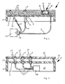
Fig. 1 zeigt eine Vorrichtung (1) mit einer Trägerplatte (2), die einen Rahmen (3) aufweist. In der Trägerplatte (2) sind Halter (4) für Enden von Lichtwellenleitern (5) angeordnet. Die Halter (4) weisen ein Außengewinde auf und sind in Bohrungen (6) der Trägerplatte (2) angeordnet, wobei die Bohrungen (6) ein Innengewinde (7) aufweisen. Durch diese Ausführungsform sind die Halter (4) in der Trägerplatte höhenverstellbar angeordnet. Nach Anordnung sämtlicher Halter (4) in der Trägerplatte (2) wird in einen von dem Rahmen (3) und der Trägerplatte (2) gebildeten Hohlraum (25) ein Verfüllmaterial (19), beispielsweise ein Tragschichtmaterial angeordnet. Es ist möglich, den Hohlraum (25) mit Beton, Reaktionsasphalt oder einem anderen Verfüllmaterial auszugießen. Die Tragschicht (19) und die Trägerplatte (2) bilden eine statische Einheit. Gleichzeitig sind die Lichtwellenleiter (5) und eine Kupplung (28) in der Vorrichtung (1) fixiert und gegen Feuchtigkeit und mechanischen Druck geschützt.Fig. 1 shows a device (1) with a carrier plate (2) having a frame (3). In the carrier plate (2) are holders (4) for ends of optical fibers (5) arranged. The holders (4) have an external thread and are arranged in bores (6) of the carrier plate (2), wherein the bores (6) have an internal thread (7). By this embodiment, the holder (4) in the support plate arranged height adjustable. After arrangement of all Holder (4) in the carrier plate (2) is in one of the cavity (3) and the support plate (2) formed (25) a filling material (19), for example a base course material arranged. It is possible the cavity (25) with concrete, reaction asphalt or other filling material pour out. The support layer (19) and the carrier plate (2) form a static unit. simultaneously are the optical fibers (5) and a coupling (28) in the device (1) fixed and against moisture and mechanical Pressure protected.
Oberhalb der Trägerplatte (2) ist eine weitere Schicht vorzugsweise aus Reaktionsasphalt (8) angeordnet. Durch diesen Reaktionsasphalt (8) werden die Halter (4) fixiert.Above the carrier plate (2) is another layer preferably arranged from reaction asphalt (8). By This reaction asphalt (8), the holder (4) are fixed.
Die Halter (4) weisen Abdeckungen (9) auf, die als Diffusor ausgebildet sind. Die Abdeckungen (9) bestehen aus einem transluszenten Material.The holders (4) have covers (9) which serve as Diffuser are formed. The covers (9) consist of a translucent material.
Die Lichtwellenleiter (5) sind über die Kupplung (28) an einem Projektor (11) über ein Lichtfaserbündel (29), welches mit einem Stecker (10) mit dem Projektor (11) verbunden ist, angeschlossen.The optical waveguides (5) are via the coupling (28) on a projector (11) via a light fiber bundle (29), which with a plug (10) connected to the projector (11) is connected.
Die Kupplung (28) ist in einem Ausschnitt (30) des Rahmens (3) von außen zugänglich angeordnet.The coupling (28) is in a cutout (30) of the Frame (3) arranged accessible from the outside.
Die Trägerplatte (2) ist als Lochblech mit Bohrungen (23) ausgebildet. Durch diese Bohrungen (23) wird das Tragschichtmaterial (19), wie in Fig. 3 noch erläutert wird, in den Hohlraum (25) vergossen.The carrier plate (2) is a perforated plate with holes (23) formed. Through these holes (23) is the support layer material (19), as will be explained in Fig. 3, in potted the cavity (25).
Der Reaktionsasphalt (8) weist eine Deckschicht (20) auf, die das Finish darstellt, das heißt, die eine ästhetisch ansprechende Oberfläche bildet.The reaction asphalt (8) has a cover layer (20) on, which represents the finish, that is, the one aesthetically appealing surface forms.
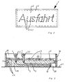
Wie in Fig. 2 dargestellt, sind die Halter (4) in der Vorrichtung (1) derart angeordnet, dass sie einen Schriftzug ergeben. Wird dieser Schriftzug beispielsweise in einer Straße angeordnet, so können Autofahrer diesen Schriftzug in der Dunkelheit erkennen und lesen. As shown in Fig. 2, the holder (4) in the Device (1) arranged such that it is a lettering result. If this lettering, for example, in a Road arranged so motorists can use this lettering recognize and read in the dark.
Fig. 3 zeigt die Trägerplatte (2) mit den Bohrungen (23). In der Trägerplatte (2) sind die Halter (4) angeordnet, die wiederum Muttern (22) tragen. In den Muttern (22) werden in einem der letzten Herstellungsschritte die Abdeckungen (9) (in Fig. 3 nicht dargestellt) angeordnet.Fig. 3 shows the carrier plate (2) with the holes (23). In the support plate (2), the holder (4) are arranged, which in turn carry nuts (22). In the nuts (22) become in one of the last manufacturing steps the covers (9) (not shown in Fig. 3) arranged.
Fig. 3 zeigt die Trägerplatte (2) mit dem mit dem Tragschichtmaterial (19) ausgegossenen Hohlraum (25). Im Tragschichtmaterial (19) sind die Lichtwellenleiter (5) und der Stecker (10) angeordnet. Das Tragschichtmaterial (19) wird durch die Bohrungen (23) der als Lochblech ausgebildeten Trägerplatte (2) gegossen. Beim Ausgießen ist die Trägerplatte auf einer Auflagefläche (21) angeordnet.Fig. 3 shows the carrier plate (2) with the with Supporting layer material (19) poured cavity (25). in the Supporting layer material (19) are the optical waveguides (5) and arranged the plug (10). The base course material (19) is through the holes (23) formed as a perforated plate Cast support plate (2). When pouring is the carrier plate arranged on a support surface (21).
Ein Hilfsrahmen (18) umgreift die Trägerplatte (2) formschlüssig, so dass ein Hohlraum (26) ebenfalls mit einem Verfüllmaterial, beispielsweise mit dem in Fig. 1 dargestellten Reaktionsasphalt (8), ausgegossen werden kann.A subframe (18) surrounds the carrier plate (2) positively, so that a cavity (26) also with a Filling material, for example, with that shown in Fig. 1 Reaction asphalt (8), can be poured out.
Gemäß der Erfindung wird die Vorrichtung, die mit dem
Beton und/oder dem Asphalt ausgegossen wird, mit folgenden
Verfahrensschritten hergestellt:
Fig. 4 zeigt die Vorrichtung (1) mit der Trägerplatte (2) und dem Rahmen (3). Neben einem Halter (4), wie er schon in Fig. 1 dargestellt ist, ist ein weiterer Halter (12) in der Trägerplatte (2) angeordnet. Dieser Halter (12) ist abgewinkelt zu einer Senkrechten der Trägerplatte (2) angeordnet. Der Halter (12) weist keine Abdeckung auf, so dass das Licht senkrecht abgestrahlt wird. Es erfolgt in diesem Fall keine diffuse Abstrahlung.Fig. 4 shows the device (1) with the carrier plate (2) and the frame (3). Next to a holder (4), like him already shown in Fig. 1, is another holder (12) arranged in the carrier plate (2). This holder (12) is angled to a vertical of the support plate (2) arranged. The holder (12) has no cover, so that the light is emitted vertically. It takes place in In this case, no diffuse radiation.
Zusätzlich ist in der Trägerplatte (2) ein Flächenlicht (13) in Form eines so genannten Lichtsteines angeordnet. Das Flächenlicht (13) besteht aus einem quaderförmigen Körper (14), der innen mit einem weißen Lack (15) beschichtet ist. Das Flächenlicht (13) trägt eine Abdeckung (16), die wiederum als Diffusor ausgebildet ist. Der Lichtwellenleiter (5) wird seitlich in das Flächenlicht (13) eingeführt, so dass eine gleichmäßige Abstrahlung des Lichtes durch die transluszente Abdeckung (16) erfolgt.In addition, in the support plate (2) is a surface light (13) arranged in the form of a so-called light stone. The area light (13) consists of a cuboid Body (14) coated inside with a white lacquer (15) is. The surface light (13) carries a cover (16), which in turn is designed as a diffuser. The optical fiber (5) is introduced laterally into the surface light (13), allowing a uniform emission of light through the translucent cover (16).
Die Schicht über der Trägerplatte (2) ist aus einem mehrschichtigen reaktiv aushärtendem Material (17) hergestellt.The layer over the carrier plate (2) is made of a multilayer reactive curing material (17).
Fig. 5 zeigt ein weiteres Ausführungsbeispiel der Vorrichtung (1). Die Trägerplatte (2) ist in diesem Fall nicht als Lochblech, sondern als Vollblech ausgebildet. In der Trägerplatte (2) sind wiederum Halter (4) für die Lichtwellenleiter (5) angeordnet. Als Abdeckung ist eine Edelstahlplatte (24) vorgesehen, durch die die Halter (4) durch in der Abdeckplatte (24) angeordnete Bohrungen (27) geführt sind. Die Abdeckungen (9) sind im vorliegenden Fall als Prismen ausgebildet, das heißt als optische Elemente. Die Lichtwellenleiter (5) und eine Kupplung (28) sind in dem Hohlraum (25) angeordnet. Über die Kupplung (28) ist ein Bündel weiterer Lichtwellenleiter anschließbar, die zu einem Projektor (in Fig. 5 nicht dargestellt) geführt sind.Fig. 5 shows a further embodiment of the device (1). The support plate (2) is not in this case as a perforated plate, but formed as a solid sheet. In the Support plate (2) are in turn holder (4) for the optical waveguide (5) arranged. As a cover is a stainless steel plate (24) provided by the holder (4) by in the cover plate (24) arranged bores (27) are. The covers (9) are in the present case as Formed prisms, that is as optical elements. The Optical waveguide (5) and a coupling (28) are in the Cavity (25) arranged. About the clutch (28) is a Bundle of further optical fibers connectable to a Projector (not shown in Fig. 5) are guided.
Die Abdeckplatte (24) ist mit Abstandsbolzen (31) an der Trägerplatte (2) befestigt. The cover plate (24) is with spacers (31) on the support plate (2) attached.
- 11
- Vorrichtungcontraption
- 22
- Trägerplattesupport plate
- 33
- Rahmenframe
- 44
- Halterholder
- 55
- Lichtwellenleiteroptical fiber
- 66
- Bohrungendrilling
- 77
- Innengewindeinner thread
- 88th
- Reaktionsasphalt (Verfüllmaterial)Reaction asphalt (filling material)
- 99
- Abdeckungencovers
- 1010
- Steckerplug
- 1111
- Projektorprojector
- 1212
- Halterholder
- 1313
- Flächenlichtarea light
- 1414
- Körperbody
- 1515
- Lackpaint
- 1616
- Abdeckungcover
- 1717
- mehrschichtiges Materialmultilayer material
- 1818
- Hilfsrahmensubframe
- 1919
- Verfüllmaterial (Tragschichtmaterial)Filling material (base course material)
- 2020
- Deckschicht (Finish)Cover layer (finish)
- 2121
- Auflageflächebearing surface
- 2222
- Mutternnuts
- 2323
- Bohrungen im Lochblech der Trägerplatte (2)Holes in the perforated plate of the carrier plate (2)
- 2424
- Abdeckplattecover
- 2525
- Hohlraumcavity
- 2626
- Hohlraumcavity
- 2727
- Bohrungen der Abdeckplatte (24)Holes in the cover plate (24)
- 2828
- Kupplungclutch
- 2929
- Faserbündelfiber bundles
- 3030
- Ausschnittneckline
- 3131
- AbstandsbolzenStandoffs
Claims (34)
dadurch gekennzeichnet, dass die Vorrichtung (1) wenigstens eine Trägerplatte (2) aufweist, und dass in und/oder an der Trägerplatte (2) wenigstens ein Halter (4) für Enden des oder der Lichtwellenleiter (5) oder Lichtwellenleiterbündel angeordnet ist.Device for arranging at least one optical waveguide or optical waveguide bundle to form a light image or a light information,
characterized in that the device (1) has at least one support plate (2), and that in and / or on the carrier plate (2) at least one holder (4) for ends of the or the optical waveguide (5) or optical fiber bundles is arranged.
dadurch gekennzeichnet, dass in einen von der Trägerplatte (2) und einem an der Trägerplatte angeordneten Rahmen (3) gebildeten Hohlraum (25) das Verfüllmaterial (8) eingebracht wird, derart, dass die Lichtwellenleiter (5) oder Lichtwellenleiterbündel von dem Material (8) umschlossen werden.Method for producing a light image or a light information with a device according to claim 1,
characterized in that the filling material (8) is introduced into a cavity (25) formed by the carrier plate (2) and a frame (3) arranged on the carrier plate, such that the optical waveguides (5) or optical fiber bundles of the material (8 ) are enclosed.
Priority Applications (1)
| Application Number | Priority Date | Filing Date | Title |
|---|---|---|---|
| EP04013845A EP1610285A1 (en) | 2004-06-14 | 2004-06-14 | Device for arrangement of at least one optical waveguide or optical waveguide bundle to form a light image or a light information and method for manufacturing of light images or light information |
Applications Claiming Priority (1)
| Application Number | Priority Date | Filing Date | Title |
|---|---|---|---|
| EP04013845A EP1610285A1 (en) | 2004-06-14 | 2004-06-14 | Device for arrangement of at least one optical waveguide or optical waveguide bundle to form a light image or a light information and method for manufacturing of light images or light information |
Publications (1)
| Publication Number | Publication Date |
|---|---|
| EP1610285A1 true EP1610285A1 (en) | 2005-12-28 |
Family
ID=34925341
Family Applications (1)
| Application Number | Title | Priority Date | Filing Date |
|---|---|---|---|
| EP04013845A Withdrawn EP1610285A1 (en) | 2004-06-14 | 2004-06-14 | Device for arrangement of at least one optical waveguide or optical waveguide bundle to form a light image or a light information and method for manufacturing of light images or light information |
Country Status (1)
| Country | Link |
|---|---|
| EP (1) | EP1610285A1 (en) |
Citations (5)
| Publication number | Priority date | Publication date | Assignee | Title |
|---|---|---|---|---|
| DE3500123A1 (en) * | 1985-01-04 | 1986-07-10 | Faseroptik Henning & Gettwart GmbH, 8501 Allersberg | Signal-displaying device for emitting light signs |
| EP0348619A2 (en) * | 1988-06-30 | 1990-01-03 | Schölly Fiberoptic Gmbh | Variable sign |
| US5651924A (en) * | 1990-11-09 | 1997-07-29 | Tchai Lights B.V. | Method for manufacturing light panels |
| US6078439A (en) * | 1998-01-19 | 2000-06-20 | Swarco Futurit Verkehrssignalsysteme Ges.Mbh | Optics unit for signal, traffic and display equipment, arrangement of the same therein and method therefore |
| US6305874B1 (en) * | 1999-05-20 | 2001-10-23 | U.S. Philips Corporation | Road-marking complex and system for marking roads |
-
2004
- 2004-06-14 EP EP04013845A patent/EP1610285A1/en not_active Withdrawn
Patent Citations (5)
| Publication number | Priority date | Publication date | Assignee | Title |
|---|---|---|---|---|
| DE3500123A1 (en) * | 1985-01-04 | 1986-07-10 | Faseroptik Henning & Gettwart GmbH, 8501 Allersberg | Signal-displaying device for emitting light signs |
| EP0348619A2 (en) * | 1988-06-30 | 1990-01-03 | Schölly Fiberoptic Gmbh | Variable sign |
| US5651924A (en) * | 1990-11-09 | 1997-07-29 | Tchai Lights B.V. | Method for manufacturing light panels |
| US6078439A (en) * | 1998-01-19 | 2000-06-20 | Swarco Futurit Verkehrssignalsysteme Ges.Mbh | Optics unit for signal, traffic and display equipment, arrangement of the same therein and method therefore |
| US6305874B1 (en) * | 1999-05-20 | 2001-10-23 | U.S. Philips Corporation | Road-marking complex and system for marking roads |
Similar Documents
| Publication | Publication Date | Title |
|---|---|---|
| WO2000039501A1 (en) | Light source element with lateral, angular light injection | |
| DE102004010920A1 (en) | Decorative component for e.g. decorating interior or exterior of building, includes translucent carrier and thin opaque layer which enables passage of small amount of light | |
| DE102005017639A1 (en) | Fiber optics arrangement for optical data communication, has crystal clear connecting material with light controlling/reflecting particles such as glass hollow balls having thin layer and arranged between light conducting units | |
| DE102008055857B4 (en) | Efficient light deflection device with two-sided prismatic and lenticular surface structuring | |
| DE102007059561B4 (en) | Luminous glass wall | |
| CH674093A5 (en) | ||
| DE10214566B4 (en) | Homogeneously parallel light-emitting light-emitting diode | |
| EP1610285A1 (en) | Device for arrangement of at least one optical waveguide or optical waveguide bundle to form a light image or a light information and method for manufacturing of light images or light information | |
| EP1130458B1 (en) | Rear projection screen | |
| DE4332458C1 (en) | Decorative panel | |
| DE2748947A1 (en) | Car internal light - has integral louvres formed by slotting lens and filling with blackening material | |
| DE10214761B4 (en) | Cladding element for buildings, in particular ceilings | |
| DE202009013588U1 (en) | Waterproof area lighting | |
| EP1669511A1 (en) | Lightweight construction element and manufacturing method | |
| DE102019105092A1 (en) | Optimized lens design for redirecting light | |
| DE102004056169A1 (en) | Arrangement for integrating light-emitting diodes in building areas | |
| DE4211971A1 (en) | Flush-mounted luminaire esp. for roads and airport - is installed at end of fibre-optic cable with exit slit illuminated by fibre bundle of predetermined length | |
| DE102009043662B4 (en) | Partially translucent cementitious or polymer bonded stone slabs | |
| DE102018215988A1 (en) | Light module, in particular for use in a lighting device for a motor vehicle | |
| EP2604767A1 (en) | Translucent compound body with spherical light conduction bodies and method for manufacture of a translucent compound body | |
| DE547002C (en) | Retroreflective signal board with a plurality of lens elements consisting of an objective lens and a collimator lens | |
| EP2565339A1 (en) | Light conducting element and translucent composite element and method for their manufacture | |
| DE4112702A1 (en) | Road reflector stud - is made of glass and is rectangular in plan, having integral reflecting surfaces at steeper angle to base than light receiving surfaces | |
| EP2604403A1 (en) | Light conduction body and light-permeable compound body | |
| DE10163975A1 (en) | Light signal safety element has internal components carrying electromagnetic radiation from diode strip to light signal module in which light signals are amplified, passed to light signal surface |
Legal Events
| Date | Code | Title | Description |
|---|---|---|---|
| PUAI | Public reference made under article 153(3) epc to a published international application that has entered the european phase |
Free format text: ORIGINAL CODE: 0009012 |
|
| AK | Designated contracting states |
Kind code of ref document: A1 Designated state(s): AT BE BG CH CY CZ DE DK EE ES FI FR GB GR HU IE IT LI LU MC NL PL PT RO SE SI SK TR |
|
| AX | Request for extension of the european patent |
Extension state: AL HR LT LV MK |
|
| AKX | Designation fees paid | ||
| 19U | Interruption of proceedings before grant |
Effective date: 20050929 |
|
| REG | Reference to a national code |
Ref country code: DE Ref legal event code: 8566 |
|
| 19W | Proceedings resumed before grant after interruption of proceedings |
Effective date: 20081001 |
|
| STAA | Information on the status of an ep patent application or granted ep patent |
Free format text: STATUS: THE APPLICATION HAS BEEN WITHDRAWN |
|
| 18W | Application withdrawn |
Effective date: 20080627 |