EP1610031B1 - Spur gear transmission - Google Patents
Spur gear transmission Download PDFInfo
- Publication number
- EP1610031B1 EP1610031B1 EP05012314A EP05012314A EP1610031B1 EP 1610031 B1 EP1610031 B1 EP 1610031B1 EP 05012314 A EP05012314 A EP 05012314A EP 05012314 A EP05012314 A EP 05012314A EP 1610031 B1 EP1610031 B1 EP 1610031B1
- Authority
- EP
- European Patent Office
- Prior art keywords
- housing
- gear
- openings
- gear housing
- bracket flange
- Prior art date
- Legal status (The legal status is an assumption and is not a legal conclusion. Google has not performed a legal analysis and makes no representation as to the accuracy of the status listed.)
- Active
Links
- 230000005540 biological transmission Effects 0.000 title description 21
- 238000001816 cooling Methods 0.000 claims abstract description 16
- 230000037431 insertion Effects 0.000 abstract 2
- 238000003780 insertion Methods 0.000 abstract 2
- 238000009423 ventilation Methods 0.000 abstract 1
- 239000003570 air Substances 0.000 description 21
- 239000000428 dust Substances 0.000 description 3
- 230000008878 coupling Effects 0.000 description 2
- 238000010168 coupling process Methods 0.000 description 2
- 238000005859 coupling reaction Methods 0.000 description 2
- 230000000694 effects Effects 0.000 description 2
- 238000004519 manufacturing process Methods 0.000 description 2
- 239000007787 solid Substances 0.000 description 2
- 238000009825 accumulation Methods 0.000 description 1
- 239000012080 ambient air Substances 0.000 description 1
- 239000013590 bulk material Substances 0.000 description 1
- 238000005266 casting Methods 0.000 description 1
- 238000010276 construction Methods 0.000 description 1
- 239000000498 cooling water Substances 0.000 description 1
- 230000001419 dependent effect Effects 0.000 description 1
- 238000009826 distribution Methods 0.000 description 1
- 238000005516 engineering process Methods 0.000 description 1
- 230000007613 environmental effect Effects 0.000 description 1
- 239000012530 fluid Substances 0.000 description 1
- 230000017525 heat dissipation Effects 0.000 description 1
- 238000005461 lubrication Methods 0.000 description 1
- 238000012423 maintenance Methods 0.000 description 1
- 239000000463 material Substances 0.000 description 1
- 238000005457 optimization Methods 0.000 description 1
- 230000007704 transition Effects 0.000 description 1
Images


Classifications
-
- F—MECHANICAL ENGINEERING; LIGHTING; HEATING; WEAPONS; BLASTING
- F16—ENGINEERING ELEMENTS AND UNITS; GENERAL MEASURES FOR PRODUCING AND MAINTAINING EFFECTIVE FUNCTIONING OF MACHINES OR INSTALLATIONS; THERMAL INSULATION IN GENERAL
- F16H—GEARING
- F16H57/00—General details of gearing
- F16H57/02—Gearboxes; Mounting gearing therein
- F16H57/025—Support of gearboxes, e.g. torque arms, or attachment to other devices
-
- F—MECHANICAL ENGINEERING; LIGHTING; HEATING; WEAPONS; BLASTING
- F16—ENGINEERING ELEMENTS AND UNITS; GENERAL MEASURES FOR PRODUCING AND MAINTAINING EFFECTIVE FUNCTIONING OF MACHINES OR INSTALLATIONS; THERMAL INSULATION IN GENERAL
- F16H—GEARING
- F16H57/00—General details of gearing
- F16H57/02—Gearboxes; Mounting gearing therein
- F16H57/033—Series gearboxes, e.g. gearboxes based on the same design being available in different sizes or gearboxes using a combination of several standardised units
-
- F—MECHANICAL ENGINEERING; LIGHTING; HEATING; WEAPONS; BLASTING
- F16—ENGINEERING ELEMENTS AND UNITS; GENERAL MEASURES FOR PRODUCING AND MAINTAINING EFFECTIVE FUNCTIONING OF MACHINES OR INSTALLATIONS; THERMAL INSULATION IN GENERAL
- F16H—GEARING
- F16H57/00—General details of gearing
- F16H57/04—Features relating to lubrication or cooling or heating
- F16H57/0412—Cooling or heating; Control of temperature
- F16H57/0415—Air cooling or ventilation; Heat exchangers; Thermal insulations
-
- F—MECHANICAL ENGINEERING; LIGHTING; HEATING; WEAPONS; BLASTING
- F16—ENGINEERING ELEMENTS AND UNITS; GENERAL MEASURES FOR PRODUCING AND MAINTAINING EFFECTIVE FUNCTIONING OF MACHINES OR INSTALLATIONS; THERMAL INSULATION IN GENERAL
- F16H—GEARING
- F16H1/00—Toothed gearings for conveying rotary motion
- F16H1/02—Toothed gearings for conveying rotary motion without gears having orbital motion
- F16H1/04—Toothed gearings for conveying rotary motion without gears having orbital motion involving only two intermeshing members
- F16H1/12—Toothed gearings for conveying rotary motion without gears having orbital motion involving only two intermeshing members with non-parallel axes
- F16H1/14—Toothed gearings for conveying rotary motion without gears having orbital motion involving only two intermeshing members with non-parallel axes comprising conical gears only
-
- Y—GENERAL TAGGING OF NEW TECHNOLOGICAL DEVELOPMENTS; GENERAL TAGGING OF CROSS-SECTIONAL TECHNOLOGIES SPANNING OVER SEVERAL SECTIONS OF THE IPC; TECHNICAL SUBJECTS COVERED BY FORMER USPC CROSS-REFERENCE ART COLLECTIONS [XRACs] AND DIGESTS
- Y10—TECHNICAL SUBJECTS COVERED BY FORMER USPC
- Y10T—TECHNICAL SUBJECTS COVERED BY FORMER US CLASSIFICATION
- Y10T74/00—Machine element or mechanism
- Y10T74/19—Gearing
- Y10T74/19642—Directly cooperating gears
- Y10T74/19679—Spur
-
- Y—GENERAL TAGGING OF NEW TECHNOLOGICAL DEVELOPMENTS; GENERAL TAGGING OF CROSS-SECTIONAL TECHNOLOGIES SPANNING OVER SEVERAL SECTIONS OF THE IPC; TECHNICAL SUBJECTS COVERED BY FORMER USPC CROSS-REFERENCE ART COLLECTIONS [XRACs] AND DIGESTS
- Y10—TECHNICAL SUBJECTS COVERED BY FORMER USPC
- Y10T—TECHNICAL SUBJECTS COVERED BY FORMER US CLASSIFICATION
- Y10T74/00—Machine element or mechanism
- Y10T74/21—Elements
- Y10T74/2186—Gear casings
- Y10T74/2189—Cooling
Definitions
- the invention relates to a spur gear, in particular a bevel helical gear with the features of the preamble of claim 1.
- Gears with a bevel gear stage are a well-known design solution to change the spatial position between the input and output shaft in addition to the important mechanical variables of speed and torque.
- the axes of input and output shafts are offset by an angle of 90 ° to each other.
- Particularly economical is the use of the bevel gear as the first stage in a mostly multi-stage transmission.
- Helical bevel gearboxes enable the parallel alignment of the drive and conveyor belt system especially for drives of conveyor systems.
- the existing program is used to derive product programs adapted to specific industry focuses, taking advantage of the existing universal product range and at the same time limiting itself to the compilation of industry-standard variants.
- For conveyor belt drives are essentially two- and three-stage Bevel helical gear used.
- For three-stage bevel-helical gearboxes a special variant with an enlarged surface of the gearbox housing by means of attached cooling fins is also provided.
- the cooling fins are applied only on the side walls of the gear housing and in the screw.
- the lantern flange is screwed to the transmission housing and provided with openings for the cooling air not described in detail. The sucked by the Axiallshareerrad cooling air flows through these passages largely unused past the gear housing.
- the invention has for its object to change the generic Kegelstirnradgetriebe for use as conveyor belt drives such that under targeted optimization of the housing shape, the amount of heat dissipated by convection can be increased permanently.
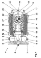
- the drive shaft 5 is part of the bevel gear stage of the transmission. Due to the lower mechanical load in the first gear stage, the relatively expensive bevel gear teeth in the manufacturing cost is attached to the input side.
- the drive shaft 5 protrudes from the front side of the transmission housing and is supported in a connected to the transmission housing housing neck 6. In the direction of the shaft input is located on the housing neck 6, a later described in more detail Lantern flange 7 for connecting a motor lantern.
- stiffening ribs 8 are attached to the top and bottom of the housing neck, which are provided with articulation points 9 for connecting an articulated torque arm.
- housing collar 11, 12th On both sides of a horizontal parting line 10 are on the upper housing part 2 and the lower housing part 3 encircling housing collar 11, 12th appropriate.
- the housing collar 11, 12 form flange-like projections, which serve to receive housing screws 13, with which the upper housing part 2 and the lower housing part 3 are screwed together.
- hubs for receiving the shafts of the gear stages and the output shaft. These hubs protrude as well as the housing collar 11, 12 from the side surfaces 16, 17 and provide further housing screws between the gear stages the required space.
- the hubs are closed by a closed housing cover 14, while the hub of the output shaft 4 is covered by an open housing cover 15.
- the closed housing cover 14 can be replaced by an open housing cover in order to use extended waves of the intermediate stages can.
- additional aggregates such. connect an auxiliary drive, a backstop or a speed monitor.
- cooling fins 18, 19 are mounted, which extend parallel to each other over the entire length of the transmission housing.
- the cooling fins 18, 19 increase the housing surface and improve the heat transfer from the transmission to the environment.
- the upper housing part 2 is closed by a bottom surface 20 and the lower housing part 3 by a bottom surface 21.
- feet 22 are provided, which serve as a straightening surface during manufacture and during transport and assembly as housing feet.
- the mounting points of the foundation bolts are located at these locations.
- the bottom of the lantern flange 7 is provided with lateral openings 23 and central openings 24 which penetrate the lantern flange 7 on either side of a horizontal median plane in the longitudinal direction of the transmission.
- the lateral openings 23 each lie with their inner edge in the extension of the side surfaces 16, 17 and the central openings 24 are each with its inner edge in the extension of the bottom surfaces 20, 21 of the transmission housing.
- the air flows from the motor lantern connected to the lantern flange on all sides (side surfaces 16, 17, bottom surfaces 20, 21) of the helical bevel gear 1.
- two stiffening ribs 8 are mounted between the lateral openings 23 and the central opening 24.
- the attached stiffening ribs 8 simultaneously form a flow channel 25, which directs the air along the bottom surfaces 20 and 21 along.
- the upper bottom surface 20 and the lower bottom surface 21 are chamfered in the direction of the central openings 24 in the lantern flange 7, whereby chamfers 26 are formed, which represent the continuation of the flow channel 25.
- chamfers 26 are formed, which represent the continuation of the flow channel 25.
- 21 cooling fins 27 are mounted to improve the heat transfer. Even in the event that the gear is inticianaus Installation directly on the ground, the bevel 26 allows the air flow under the transmission through.
- cooling fins 18, 19 run by a slight angling on the side openings 23 of the lantern flange 7 and are thereby adapted in the direction of the housing neck 6 of the air flow.
- the air flow is passed through this slight bend to the end of the entire side surfaces 16, 17 of the transmission housing.
- the continuous air flow guide without abrupt jumps or transitions on all boundary or outer surfaces (side surfaces 16, 17, bottom surfaces 20, 21) leads to a significantly improved heat transfer by forced convection to the air of the environment.
- the guided air flow prevents the ever-present dust settles in the ambient air on the gear housing and forms insulating dirt nests.
- the housing forms of the known universal transmission for a conveyor belt drive must also take into account the requirements of other applications. This compromise leads to a poorer heat balance, which leads to an uneconomical oversizing of the drive in this application.
- FIG. 3 shows the entire drive train of a conveyor belt drive using a helical bevel gear 1.
- the gear housing is supported on a foundation or a machine frame via a torque arm 28 which engages in the articulation points 9 of the stiffening ribs 8.
- the drive shaft 5 of the helical bevel gear 1 is connected via a brake 32 and a fluid coupling 33 with the output shaft of an electric motor 34 serving as a drive.
- the electric motor 34 is flanged to the transmission housing via a motor lantern 31 and the lantern flange 7.
- the motor lantern 31 is designed for connection of the electric motor 34 designed as a flange motor. Since the motor lantern 31 must transmit considerable weight forces to the drive bearing on the output shaft 4, is also Here, by the cast on the housing neck 6 of the gear housing lantern flange 7 a shortened connection of the gear housing and electric motor 34 is an advantageous design solution.
- an axial fan 29 is secured against rotation directly on the drive shaft 5 of the helical bevel gear 1.
- the motor lantern 31 is provided with sufficiently large air inlet openings 35.
- these air inlet openings 35 are provided with components not shown here for engagement protection or dust-proof hoods.
- the mounted directly on the drive shaft 5 axial fan 29 rotates with the high engine speed. As a result, the promotion of a high air flow is ensured in any operating condition. This air flow passes through the openings 23, 24 in the lantern flange 7 and is guided on the cooling fins 18, 19, 27 on the side surfaces 16, 17 and the bottom surfaces 20, 21 along.
Landscapes
- Engineering & Computer Science (AREA)
- General Engineering & Computer Science (AREA)
- Mechanical Engineering (AREA)
- General Details Of Gearings (AREA)
- Gear Transmission (AREA)
- Gears, Cams (AREA)
- Analysing Materials By The Use Of Radiation (AREA)
- Mechanical Pencils And Projecting And Retracting Systems Therefor, And Multi-System Writing Instruments (AREA)
- Retarders (AREA)
Abstract
Description
Die Erfindung betrifft ein Stirnradgetriebe, insbesondere ein Kegelstirnradgetriebe mit den Merkmalen des Oberbegriffs des Anspruches 1.The invention relates to a spur gear, in particular a bevel helical gear with the features of the preamble of
Getriebe mit einer Kegelradstufe sind eine allgemein bekannte Konstruktionslösung, um neben den wichtigen mechanischen Größen von Drehzahl und Drehmoment auch die räumliche Lage zwischen der Antriebs- und Abtriebswelle zu ändern. Üblicherweise liegen die Achsen von Antriebs- und Abtriebswelle um einen Winkel von 90° zueinander versetzt. Besonders wirtschaftlich ist die Verwendung des Kegelradsatzes als erste Stufe in einem meist mehrstufigen Getriebe. Insbesondere für Antriebe von Förderbandanlagen ermöglichen Kegelstirnradgetriebe die parallele Ausrichtung von Antrieb und Förderbandanlage.Gears with a bevel gear stage are a well-known design solution to change the spatial position between the input and output shaft in addition to the important mechanical variables of speed and torque. Usually, the axes of input and output shafts are offset by an angle of 90 ° to each other. Particularly economical is the use of the bevel gear as the first stage in a mostly multi-stage transmission. Helical bevel gearboxes enable the parallel alignment of the drive and conveyor belt system especially for drives of conveyor systems.
Mit einem minimalen Umfang an Einzelteilen kann eine viele Baugrößen umfassende Universalgetriebebaureihe erzeugt werden. Die Einzelteile werden technisch in einem optimalen Arbeitspunkt ausgelegt. Aufgrund der hohen Wiederholhäufigkeit einzelner Teile in verschiedenen Varianten hat dieses Konzept zudem besondere wirtschaftliche Vorteile.With a minimal amount of parts, a wide range of universal gearboxes can be produced. The individual parts are designed technically in an optimal operating point. Due to the high frequency of repetition of individual parts in different variants, this concept also has special economic advantages.
Es existiert für eine Vielzahl vergleichbarer Getriebereihen nach dem Baukastenprinzip ein Programm, das sowohl Stirnrad- als auch Kegelstirnradgetriebe umfasst. Die Getriebe sind für alle denkbaren Einbaulagen und mit unterschiedlichsten Bauformen der An- und Abtriebswellen verfügbar. Kennzeichnend ist die Verwendung eines weitgehend unveränderten Grundgehäuses sowohl für die Stirnrad- als auch für die Kegelstirnradgetriebe. Wahlweise sind auch weitere Zusatzkomponenten, wie z.B. Rücklaufsperren und Bremsen, erhältlich.There is a program for a variety of comparable transmission series according to the modular principle, which includes both helical and helical bevel gear. The gearboxes are available for all imaginable mounting positions and with different designs of the input and output shafts. Characteristic is the use of a largely unchanged basic housing both for the helical and the bevel helical gear. Optionally, other additional components, such as e.g. Backstops and brakes, available.
Aus dem vorhandenen Programm leiten sich für besondere Branchenschwerpunkte angepasste Produktprogramme ab, die die Vorteile der vorhandenen Universalbaureihe nutzen und sich gleichzeitig auf die Zusammenstellung der branchenüblichen Varianten beschränken. Für Förderbandantriebe werden im wesentlichen zwei- und dreistufige Kegelstirnradgetriebe eingesetzt. Für dreistufige Kegelstirnradgetriebe ist auch eine Sondervariante mit einer vergrößerten Oberfläche des Getriebegehäuses durch aufgesetzte Kühlrippen vorgesehen.The existing program is used to derive product programs adapted to specific industry focuses, taking advantage of the existing universal product range and at the same time limiting itself to the compilation of industry-standard variants. For conveyor belt drives are essentially two- and three-stage Bevel helical gear used. For three-stage bevel-helical gearboxes, a special variant with an enlarged surface of the gearbox housing by means of attached cooling fins is also provided.
Nachteilig an dem Konzept eines universalen Baukastengetriebes ist für branchenspezifische Anwendungen die durchgängige Verwendung von Gleichteilen. Hier ist insbesondere das Getriebegehäuse zu nennen. Neben der mechanischen Belastung ist die Wärmegrenzleistung ein bestimmendes Auslegungskriterium für Förderbandantriebe. Da im allgemeinen in Tagebauen oder ähnlichen Anwendungsfällen zur Förderung von Schüttgütern kein Kühlwasser verfügbar ist und der Einsatz anderer Kühl- und Schmieranlagen, wie z. B. Öl-Luftkühler, aus unterschiedlichsten Gründen nicht möglich ist, muss die gesamte Getriebewärme an die Luft über Konvektion abgegeben werden. Zusätzlich erschweren die an dem betreffenden Einsatzort herrschenden rauen Umgebungsbedingungen mit einem hohen Staubanfall die Aufrechterhaltung der Wärmeabfuhr, da auf dem Getriebegehäuse abgelagerte Staubschichten isolierend wirken. Bekannt sind in diesem Zusammenhang Kegelstirnradgetriebe mit einer durch Kühlrippen vergrößerten Gehäuseoberfläche und mit einem auf der Antriebswelle angeordneten Axiallüfterrad.A disadvantage of the concept of a universal modular gearbox for industry-specific applications is the consistent use of identical parts. In particular, the transmission housing should be mentioned here. In addition to the mechanical load, the thermal rating is a decisive design criterion for conveyor belt drives. Since generally in opencast mines or similar applications for the promotion of bulk solids no cooling water is available and the use of other cooling and lubrication systems, such as. B. oil-air cooler, for various reasons is not possible, the entire transmission heat must be delivered to the air via convection. In addition, the prevailing at the site of use harsh environmental conditions with a high dust accumulation complicate the maintenance of heat dissipation, as deposited on the gear housing dust layers have an insulating effect. Bevel gear units are known in this context with an enlarged by cooling fins housing surface and with an arranged on the drive shaft Axiallüfterrad.
Bei einem aus der gattungsgemâßen
Der Erfindung liegt die Aufgabe zugrunde, das gattungsgemäße Kegelstirnradgetriebe für den Einsatz als Förderbandantriebe derart zu ändern, dass unter gezielter Optimierung der Gehäuseform die mittels Konvektion abgeführte Wärmemenge dauerhaft erhöht werden kann.The invention has for its object to change the generic Kegelstirnradgetriebe for use as conveyor belt drives such that under targeted optimization of the housing shape, the amount of heat dissipated by convection can be increased permanently.
Die zugrundeliegende Aufgabe wird bei einem gattungsgemäßen Stirnradgetriebe erfindungsgemäß durch die kennzeichnenden Merkmale des Anspruchs 1 gelöst. Vorteilhafte Ausgestaltungen der Erfindung sind Gegenstand der Unteransprüche.The underlying object is achieved according to the invention in a generic spur gear by the characterizing features of
Die Erfindung und die mit der Erfindung verbundenen Vorteile werden nachfolgend anhand von zwei in der Zeichnung dargestellten Ausführungsbeispielen näher erläutert. Es zeigen:
- Fig. 1
- die Seitenansicht auf ein Kegelstirnradgetriebe eines Ausführungsbeispiels nach der Erfindung;
- Fig. 2
- eine räumliche Ansicht auf die seite der Antriebswelle des Kegelstirnradgetriebes gemäß
Fig. 1 und - Fig. 3
- den Aufbau eines typischen Förderbandantriebs in Seitenansicht und teilweise als Längsschnitt eines weiteren Ausführungsbeispiels nach der Erfindung.
- Fig. 1
- the side view of a bevel helical gear of an embodiment of the invention;
- Fig. 2
- a spatial view on the side of the drive shaft of the bevel helical gear according to
Fig. 1 and - Fig. 3
- the structure of a typical conveyor belt drive in side view and partly as a longitudinal section of another embodiment of the invention.
In
Die Antriebswelle 5 ist ein Teil der Kegelradstufe des Getriebes. Aufgrund der geringeren mechanischen Belastung in der ersten Getriebestufe wird die in den Herstellkosten relativ teure Kegelradverzahnung an der Eingangsseite angebracht. Die Antriebswelle 5 ragt stirnseitig aus dem Getriebegehäuse heraus und stützt sich in einem mit dem Getriebegehäuse verbundenen Gehäusehals 6 ab. In Richtung des Welleneingangs befindet sich an dem Gehäusehals 6 ein später näher beschriebener Laternenflansch 7 zum Anschluss einer Motorlaterne. In einer vertikalen Ebene sind an der Ober- und Unterseite des Gehäusehalses 6 Versteifungsrippen 8 befestigt, die mit Anlenkpunkten 9 zur Anbindung einer gelenkigen Drehmomentenstütze versehen sind.The
Beiderseits einer horizontalen Teilfuge 10 sind an dem Gehäuseoberteil 2 und dem Gehäuseunterteil 3 umlaufende Gehäusekragen 11, 12 angebracht. Die Gehäusekragen 11, 12 bilden flanschartige Vorsprünge, die der Aufnahme von Gehäuseschrauben 13 dienen, mit denen das Gehäuseoberteil 2 und das Gehäuseunterteil 3 miteinander verschraubt werden.On both sides of a
In den Seitenflächen 16, 17 des Gehäuseoberteils 2 und des Gehäuseunterteils 3 befinden sich Naben zur Aufnahme der Wellen der Getriebestufen und der Abtriebswelle. Diese Naben ragen ebenso wie die Gehäusekragen 11, 12 aus den Seitenflächen 16, 17 hervor und bieten weiteren Gehäuseschrauben zwischen den Getriebestufen den erforderlichen Bauraum. Die Naben sind durch einen geschlossenen Gehäusedeckel 14 verschlossen, während die Nabe der Abtriebswelle 4 durch einen offenen Gehäusedeckel 15 abgedeckt ist.In the
Wahlweise kann der geschlossene Gehäusedeckel 14 durch einen offenen Gehäusedeckel ersetzt werden, um verlängerte Wellen der Zwischenstufen einsetzen zu können. Hieran lassen sich mögliche Zusatzaggregate, wie z.B. ein Hilfsantrieb, eine Rücklaufsperre oder ein Drehzahlwächter anschließen.Optionally, the closed
Auf den Seitenflächen 16, 17 des Gehäuseoberteiles 2 und des Gehäuseunterteiles 3 sind Kühlrippen 18, 19 angebracht, die sich parallel zueinander über die gesamte Länge des Getriebegehäuses erstrecken. Die Kühlrippen 18, 19 vergrößern die Gehäuseoberfläche und verbessern den Wärmeübergang von dem Getriebe an die Umgebung.On the
An den der Teilfuge 10 gegenüberliegenden Seiten ist das Gehäuseoberteil 2 durch eine Bodenfläche 20 und das Gehäuseunterteil 3 durch eine Bodenfläche 21 verschlossen. An den Bodenflächen 20, 21 sind Füße 22 vorgesehen, die bei der Fertigung als Richtfläche und bei dem Transport und der Montage als Gehäusefüße dienen. Für ein Getriebe in Fußausführung befinden sich an diesen Stellen die Aufnahmepunkte der Fundamentschrauben.At the opposite side of the
Die räumliche Darstellung des Kegelstirnradgetriebes 1 in
Der Boden des Laternenflansches 7 ist mit seitlichen Öffnungen 23 und mittleren Öffnungen 24 versehen, die den Laternenflansch 7 beiderseits einer horizontalen Mittelebene in Längsrichtung des Getriebes durchdringen. Die seitlichen Öffnungen 23 liegen jeweils mit ihrer inneren Kante in der Verlängerung der Seitenflächen 16, 17 und die mittleren Öffnungen 24 liegen jeweils mit ihrer inneren Kante in der Verlängerung der Bodenflächen 20, 21 des Getriebegehäuses. Erst die verfahrenstechnische Beherrschung der Gießtechnik von aufwendigen Bauteilen mit höchst unterschiedlicher Materialverteilung in dieser erheblichen räumlichen Erstreckung erlaubt die direkte formschlüssige Verbindung des Laternenflansches 7 am Gehäusehals 6 des Kegelstirnradgetriebes 1. Durch das Anformen des Laternenflansches 7 an den Gehäusehals 6 bildet dieser zusammen mit dem Gehäuseoberteil 2 und dem Gehäuseunterteil 3 jeweils ein Stück und stellt damit einen Teil des Getriebegehäuses dar. Als Folge dieser vorteilhaften Gestaltung baut das Getriebe kürzer.The bottom of the
Durch die Öffnungen 23, 24 strömt die Luft aus der an den Laternenflansch angeschlossenen Motorlaterne an allen Seiten (Seitenflächen 16, 17, Bodenflächen 20, 21) des Kegelstirnradgetriebes 1 entlang. Um eine hinreichende Steifigkeit der Konstruktion des Laternenflansches 7 zu erreichen, sind zwischen den seitlichen Öffnungen 23 und der mittleren Öffnung 24 zwei Versteifungsrippen 8 angebracht. Die angebrachten Versteifungsrippen 8 bilden gleichzeitig einen Strömungskanal 25, der die Luft an den Bodenflächen 20 und 21 entlang leitet.Through the
Vorteilhafterweise sind die obere Bodenfläche 20 und die untere Bodenfläche 21 in Richtung auf die mittleren Öffnungen 24 im Laternenflansch 7 abgeschrägt, wodurch Abschrägungen 26 entstehen, die die Fortsetzung des Strömungskanals 25 darstellen. Auf den Bodenflächen 20, 21 sind Kühlrippen 27 zur Verbesserung des Wärmeübergangs angebracht. Auch für den Fall, dass das Getriebe in Fußausführung direkt auf dem Boden steht, erlaubt die Abschrägung 26 die Luftführung unter dem Getriebe hindurch.Advantageously, the
Ebenso wie durch die mittleren Öffnungen 24 strömt Luft durch die seitlichen Öffnungen 23 an den Kühlrippen 18, 19 der Seitenflächen 16, 17 entlang. Die Kühlrippen 18, 19 laufen durch eine leichte Abwinklung auf die seitlichen Öffnungen 23 des Laternenflansches 7 zu und sind dadurch in Richtung des Gehäusehalses 6 der Luftströmung angepasst. Der Luftstrom wird durch diese leichte Abwinkelung bis zum Ende der gesamten Seitenflächen 16, 17 des Getriebegehäuses geleitet.As well as through the
Die kontinuierliche Luftstromführung ohne abrupte Sprünge oder Übergänge an allen Begrenzungs- oder Außenflächen (Seitenflächen 16, 17, Bodenflächen 20 , 21) führt zu einem deutlich verbesserten Wärmeübergang durch erzwungene Konvektion an die Luft der Umgebung. Außerdem verhindert der geführte Luftstrom, dass sich der immer vorhandene Staub in der Umgebungsluft auf dem Getriebegehäuse absetzt und isolierende Drecknester bildet.The continuous air flow guide without abrupt jumps or transitions on all boundary or outer surfaces (side surfaces 16, 17, bottom surfaces 20, 21) leads to a significantly improved heat transfer by forced convection to the air of the environment. In addition, the guided air flow prevents the ever-present dust settles in the ambient air on the gear housing and forms insulating dirt nests.
Im Gegensatz zu dem erfindungsgemäßen Getriebegehäuse müssen die Gehäuseformen der bekannten Universalgetriebe für einen Förderbandantrieb auch die Anforderungen anderer Anwendungen berücksichtigen. Dieser Kompromiss führt zu einem schlechteren Wärmehaushalt, der in diesem Anwendungsfall zu einer unwirtschaftlichen Überdimensionierung des Antriebs führt.In contrast to the transmission housing according to the invention, the housing forms of the known universal transmission for a conveyor belt drive must also take into account the requirements of other applications. This compromise leads to a poorer heat balance, which leads to an uneconomical oversizing of the drive in this application.
Die Darstellung des weiteren Ausführungsbeispiels in
Die Antriebswelle 5 des Kegelstirnradgetriebes 1 ist über eine Bremse 32 und eine Flüssigkeitskupplung 33 mit der Abtriebswelle eines als Antrieb dienenden Elektromotors 34 verbunden. Der Elektromotor 34 ist über eine Motorlaterne 31 und den Laternenflansch 7 an das Getriebegehäuse angeflanscht. Die Motorlaterne 31 ist für den Anschluss des als Flanschmotor ausgebildeten Elektromotors 34 ausgelegt. Da die Motorlaterne 31 erhebliche Gewichtskräfte zu der Antriebslagerung an der Abtriebswelle 4 übertragen muss, ist auch hierbei durch den an den Gehäusehals 6 des Getriebegehäuse angegossenen Laternenflansch 7 eine verkürzte Verbindung von Getriebegehäuse und Elektromotor 34 eine vorteilhafte Konstruktionslösung.The
Unmittelbar im Anschluss an den Laternenflansch 7 ist direkt auf der Antriebswelle 5 des Kegelstirnradgetriebes 1 ein Axiallüfterrad 29 drehfest befestigt. Die Motorlaterne 31 ist mit ausreichend großen Lufteinlassöffnungen 35 versehen. Aus Gründen der Betriebssicherheit sind diese Lufteinlassöffnungen 35 mit hier nicht dargestellten Bauteilen zum Eingriffsschutz bzw. staubabweisenden Hauben versehen. Das direkt auf der Antriebswelle 5 angebrachte Axiallüfterrad 29 dreht mit der hohen Motordrehzahl. Dadurch wird in jedem Betriebszustand die Förderung eines hohen Luftstroms gewährleistet. Dieser Luftstrom tritt durch die Öffnungen 23, 24 im Laternenflansch 7 hindurch und wird an den Kühlrippen 18, 19, 27 an den Seitenflächen 16, 17 und den Bodenflächen 20, 21 entlang geführt.Immediately following the
Die Wirkung der Luftströmung kann noch durch die Verwendung einer Luftleithaube 30 erhöht werden, die den Gehäusehals 6 im Anschluss an den Laternenflansch umgibt. Der Innendurchmesser der Luftleithaube 30 ist geringfügig größer als die radial größten Abmessungen der Öffnungen 23, 24 im Laternenflansch 7. Somit wird die gesamte Luftströmung in einem Ringkanal zwischen Gehäusehals 6 und Luftleithaube 30 direkt und verlustarm zu den wärmsten Stellen an den Seitenflächen 16, 17 und Bodenflächen 20, 21 geführt.The effect of the air flow can still be increased by the use of an
Claims (4)
- Spur gear unit, in particular bevel spur gear unit with one or more gear stages and a gear housing which encloses the gear stages and presents two side shells (16, 17) with lateral cooling ribs (18, 19) as well as an upper and a lower bottom shell (20, 21) which close the gear housing, wherein the spur gear unit is provided with a driving shaft (5) which protrudes at the front side from the gear housing and onto which an axial blower wheel (29) is torsion-proof fixed outside the gear housing and wherein a bracket flange (7) provided with openings for the connection of a motor bracket (31) is connected with the gear housing, characterized in that the bracket flange (7) is attached to the gear housing and forms a unit with the same, that cooling ribs (27) are also fitted on both bottom shells (20, 21), that the bracket flange (7) is provided with lateral openings (23) and central openings (24) which penetrate the bracket flange (7) on both sides of a horizontal central plane in longitudinal direction of the gear unit, and that the central openings (24) are lying in the extension of the bottom shells (20, 21) and the lateral openings (23) in the extension of the side shells (16, 17) of the gear housing.
- Spur gear unit according to claim 1, characterized in that the cooling ribs (18, 19) fitted on the side shells (16, 17) of the gear housing are running towards the lateral openings (23) in the bracket flange (7).
- Spur gear unit according to claim 1 or 2, characterized in that the upper and the lower bottom shells (20, 21) of the gear housing are beveled towards the central openings (24) in the bracket flange (7).
- Spur gear unit according to one of claims 1 to 3, characterized in that, between the bracket flange (7) and the outside shells of the gear housing, at its front side an air baffle hood (30) is provided whose inside diameter is larger than the radially largest dimensions of the openings (23, 24) in the bracket flange (7).
Priority Applications (1)
| Application Number | Priority Date | Filing Date | Title |
|---|---|---|---|
| PL05012314T PL1610031T3 (en) | 2004-06-22 | 2005-06-08 | Spur gear transmission |
Applications Claiming Priority (2)
| Application Number | Priority Date | Filing Date | Title |
|---|---|---|---|
| DE102004030180A DE102004030180A1 (en) | 2004-06-22 | 2004-06-22 | Spur gears |
| DE102004030180 | 2004-06-22 |
Publications (3)
| Publication Number | Publication Date |
|---|---|
| EP1610031A2 EP1610031A2 (en) | 2005-12-28 |
| EP1610031A3 EP1610031A3 (en) | 2007-07-25 |
| EP1610031B1 true EP1610031B1 (en) | 2008-10-15 |
Family
ID=35058420
Family Applications (1)
| Application Number | Title | Priority Date | Filing Date |
|---|---|---|---|
| EP05012314A Active EP1610031B1 (en) | 2004-06-22 | 2005-06-08 | Spur gear transmission |
Country Status (10)
| Country | Link |
|---|---|
| US (1) | US8555747B2 (en) |
| EP (1) | EP1610031B1 (en) |
| CN (1) | CN100540953C (en) |
| AT (1) | ATE411484T1 (en) |
| AU (1) | AU2005202339B8 (en) |
| BR (1) | BRPI0502314B1 (en) |
| DE (2) | DE102004030180A1 (en) |
| DK (1) | DK1610031T3 (en) |
| PL (1) | PL1610031T3 (en) |
| ZA (1) | ZA200504658B (en) |
Families Citing this family (24)
| Publication number | Priority date | Publication date | Assignee | Title |
|---|---|---|---|---|
| DE102007008658A1 (en) * | 2007-02-20 | 2008-08-21 | Flender Industriegetriebe Gmbh & Co. Kg | Bevel gear units, in particular bevel helical gear units |
| DE102008004337B4 (en) | 2007-04-13 | 2023-10-05 | Sew-Eurodrive Gmbh & Co Kg | Housing for a gearbox, gearbox and gearbox series |
| DE102009014314B4 (en) | 2009-03-25 | 2024-05-16 | Sew-Eurodrive Gmbh & Co Kg | transmission |
| JP5682756B2 (en) * | 2011-03-14 | 2015-03-11 | コベルコ建機株式会社 | Construction machine drive |
| WO2012123042A1 (en) * | 2011-03-17 | 2012-09-20 | Sew-Eurodrive Gmbh & Co. Kg | Transmission device |
| WO2012123043A1 (en) * | 2011-03-17 | 2012-09-20 | Sew-Eurodrive Gmbh & Co. Kg | Transmission device |
| CN103649598B (en) * | 2011-03-17 | 2017-07-11 | Sew-传动设备有限责任公司 | Reducer arrangement |
| WO2012123046A1 (en) * | 2011-03-17 | 2012-09-20 | Sew-Eurodrive Gmbh & Co. Kg | Transmission device |
| WO2012123045A1 (en) * | 2011-03-17 | 2012-09-20 | Sew-Eurodrive Gmbh & Co. Kg | Transmission device |
| US20140260788A1 (en) * | 2011-10-05 | 2014-09-18 | Schaeffler Technologies Gmbh & Co. Kg | Gearbox device with cooled dry-sump area |
| EP2653752A1 (en) * | 2012-04-18 | 2013-10-23 | Siemens Aktiengesellschaft | Series of gear housings |
| CN103591266A (en) * | 2012-08-14 | 2014-02-19 | 苏州市兴博塑胶模具有限公司 | Gear box placing plate |
| CN103470742A (en) * | 2013-09-26 | 2013-12-25 | 沃德(天津)传动有限公司 | Reduction gear |
| CN104107006B (en) * | 2014-08-06 | 2017-02-15 | 中山市金舜家庭用品有限公司 | Suction unit for window wiper |
| DE102015011163B4 (en) * | 2015-04-13 | 2022-07-14 | Sew-Eurodrive Gmbh & Co Kg | Transmission comprising a shaft, a flange part and a housing part |
| US10900558B2 (en) | 2016-12-02 | 2021-01-26 | Sew-Eurodrive Gmbh & Co. Kg | Gearbox with a housing which has a lower housing part, onto which an upper housing part is placed |
| CN106989165A (en) * | 2017-05-25 | 2017-07-28 | 贵州大学 | One kind is used for Hydrodynamic transmission heat radiating type housing |
| CN108302161A (en) * | 2017-12-18 | 2018-07-20 | 珠海格力智能装备有限公司 | Gear drive |
| DE102019207683A1 (en) * | 2019-05-25 | 2020-11-26 | Robert Bosch Gmbh | Magnetorheological device |
| JP7373987B2 (en) * | 2019-12-26 | 2023-11-06 | 住友重機械工業株式会社 | Orthogonal reduction gear |
| RU206562U1 (en) * | 2020-12-29 | 2021-09-15 | Общество С Ограниченной Ответственностью "Корум Груп" | CONVEYOR DRIVE UNIT |
| DE102021205526A1 (en) * | 2021-05-31 | 2022-12-01 | Dana Motion Systems Deutschland GmbH | air cooling arrangement |
| CN117006231A (en) | 2022-04-28 | 2023-11-07 | Sew-工业减速机(天津)有限公司 | Speed reducer with two housing parts identical in construction to each other |
| WO2023208414A1 (en) | 2022-04-28 | 2023-11-02 | Sew-Eurodrive Gmbh & Co. Kg | Transmission with housing parts, in particular two identically designed housing parts |
Family Cites Families (37)
| Publication number | Priority date | Publication date | Assignee | Title |
|---|---|---|---|---|
| BE527697A (en) * | ||||
| US407590A (en) * | 1889-07-23 | Territory | ||
| FR527697A (en) | 1920-11-26 | 1921-10-28 | Societe Noel Aine Pellegrini & Cie | Transformer for electric heating |
| GB294717A (en) * | 1927-05-06 | 1928-08-02 | Gen Electric Co Ltd | Improvements in or relating to worm gearing |
| GB294317A (en) | 1927-05-16 | 1928-07-26 | Gen Electric Co Ltd | Improvements in or relating to electric coupling devices |
| DE589762C (en) * | 1928-12-23 | 1933-12-13 | Friedrich Deckel Praez Smechan | Assembly of gearbox and electric motor using an intermediate ring |
| US2147391A (en) * | 1935-10-15 | 1939-02-14 | Cleveland Worm And Gear Compan | Reduction gear |
| US2391186A (en) * | 1943-06-12 | 1945-12-18 | Cleveland Worm & Gear Company | Air-cooled reduction gear unit |
| DE858920C (en) * | 1943-09-30 | 1952-12-11 | Zahnraederfabrik Augsburg Vorm | Worm gear with airflow cooling |
| US2481914A (en) * | 1944-03-02 | 1949-09-13 | Cleveland Worm & Gear Company | Air-cooled reduction gear unit |
| US2511479A (en) * | 1945-06-28 | 1950-06-13 | Prec Developments Co Ltd | Cooling means for reduction gearing |
| US2548805A (en) * | 1946-08-16 | 1951-04-10 | Foote Bros Gear And Machine Co | Casing structure for reduction drive units |
| US2600912A (en) * | 1947-02-19 | 1952-06-17 | Gordon L Olson | Speed reducing mechanism |
| US3045430A (en) * | 1960-09-20 | 1962-07-24 | John E Becker | Fluid couplings |
| US3353591A (en) * | 1965-02-15 | 1967-11-21 | Tsnii Teknologii I Mash | Apparatus for cooling gear reduction units |
| GB1090342A (en) * | 1965-02-23 | 1967-11-08 | Tsnii T I Mash | A transmission unit having means for cooling the same |
| DE1984404U (en) * | 1966-07-28 | 1968-04-25 | Westdeutsche Getriebewerk Gmbh | BEVEL AND BEVEL GEAR GEAR TRANSMISSIONS. |
| US3667318A (en) * | 1970-09-18 | 1972-06-06 | Power Parts Co | Lightweight gear housing |
| US3710646A (en) * | 1970-11-23 | 1973-01-16 | Bogan D Corp | Gear housing |
| AT345051B (en) * | 1974-08-07 | 1978-08-25 | Louis Joerg Ges M B H | DEVICE FOR COOLING A LUBRICANT-FILLED, COOLING-FIBED GEARBOX BY USING A BUILT-ON FAN |
| DE3414476A1 (en) * | 1984-04-17 | 1985-10-24 | Glyco-Maschinenbau GmbH, 4300 Essen | SLIDE BEARING HOUSING |
| US4872502A (en) * | 1987-09-25 | 1989-10-10 | The Falk Company | Air cooling of enclosed gear drives |
| DE8805009U1 (en) * | 1988-04-15 | 1988-05-26 | J.M. Voith Gmbh, 7920 Heidenheim, De | |
| US5070958A (en) * | 1991-03-15 | 1991-12-10 | General Motors Corporation | Variable effort steering gear |
| US5207121A (en) * | 1992-02-13 | 1993-05-04 | General Motors Corporation | Gear case for locomotive drive system |
| DE4220624A1 (en) * | 1992-06-24 | 1994-01-05 | Zahnradfabrik Friedrichshafen | Rotary slide valve, especially for power steering |
| CN1084622A (en) * | 1992-09-25 | 1994-03-30 | 陈骅 | Roller cam speed-reducer |
| DE4315895B4 (en) | 1993-05-12 | 2008-04-03 | Zf Friedrichshafen Ag | Steering booster |
| US5505101A (en) * | 1993-08-10 | 1996-04-09 | Lloyd S. Curtis | Gearbox |
| DE4330338C1 (en) * | 1993-09-08 | 1994-09-08 | Daimler Benz Ag | Fluid, in particular hydraulic servo control |
| GB2282206B (en) * | 1993-09-23 | 1997-10-08 | Brown Gear Ind | Gearbox |
| CN2246731Y (en) * | 1995-10-20 | 1997-02-05 | 邱福田 | Structure-improved worm reducer |
| JP3832861B2 (en) * | 1996-12-13 | 2006-10-11 | 住友重機械工業株式会社 | Universal mounting housing structure for orthogonal gearbox and gearmotor |
| BE1011158A3 (en) * | 1997-05-20 | 1999-05-04 | Atlas Copco Airpower Nv | Connector that connects the cover of a drive with the cover of a compressor element. |
| FR2822913B1 (en) * | 2001-04-03 | 2004-10-01 | Commerciale Et D Engineering S | TRANSMISSION DEVICE BETWEEN A PRIMARY SHAFT OUTPUT MOTOR AND LAWN MOWER COMPRISING SUCH A DEVICE |
| DE10131753A1 (en) | 2001-07-03 | 2003-01-23 | Mercedes Benz Lenkungen Gmbh | Recoiling arrangement on a hydraulic servo valve arrangement comprises a valve device which on pressurization is oriented in the middle position of the servo valve |
| US7066046B1 (en) * | 2003-02-24 | 2006-06-27 | Gibson Randolph P | Method for making speed reducers |
-
2004
- 2004-06-22 DE DE102004030180A patent/DE102004030180A1/en not_active Ceased
- 2004-12-10 US US11/009,422 patent/US8555747B2/en active Active
-
2005
- 2005-05-30 AU AU2005202339A patent/AU2005202339B8/en not_active Ceased
- 2005-06-08 EP EP05012314A patent/EP1610031B1/en active Active
- 2005-06-08 DE DE502005005669T patent/DE502005005669D1/en active Active
- 2005-06-08 AT AT05012314T patent/ATE411484T1/en not_active IP Right Cessation
- 2005-06-08 DK DK05012314T patent/DK1610031T3/en active
- 2005-06-08 PL PL05012314T patent/PL1610031T3/en unknown
- 2005-06-21 BR BRPI0502314-9A patent/BRPI0502314B1/en active IP Right Grant
- 2005-06-21 CN CNB2005100789600A patent/CN100540953C/en active Active
-
2006
- 2006-02-08 ZA ZA200504658A patent/ZA200504658B/en unknown
Also Published As
| Publication number | Publication date |
|---|---|
| ATE411484T1 (en) | 2008-10-15 |
| CN100540953C (en) | 2009-09-16 |
| EP1610031A3 (en) | 2007-07-25 |
| BRPI0502314A (en) | 2006-02-07 |
| US20060000301A1 (en) | 2006-01-05 |
| AU2005202339B8 (en) | 2012-08-09 |
| US8555747B2 (en) | 2013-10-15 |
| DE502005005669D1 (en) | 2008-11-27 |
| CN1712756A (en) | 2005-12-28 |
| AU2005202339A1 (en) | 2006-01-12 |
| ZA200504658B (en) | 2006-03-29 |
| AU2005202339B2 (en) | 2012-04-12 |
| EP1610031A2 (en) | 2005-12-28 |
| PL1610031T3 (en) | 2009-04-30 |
| DE102004030180A1 (en) | 2006-02-09 |
| BRPI0502314B1 (en) | 2018-07-10 |
| DK1610031T3 (en) | 2009-02-23 |
Similar Documents
| Publication | Publication Date | Title |
|---|---|---|
| EP1610031B1 (en) | Spur gear transmission | |
| EP1961993B1 (en) | Bevel gear, in particular bevel spur gear | |
| EP2411706B1 (en) | Transmission | |
| EP2411703B1 (en) | Transmission | |
| EP2411705B1 (en) | Transmission | |
| EP2411702B1 (en) | Transmission that is at least partially filled with oil | |
| EP2411704B1 (en) | Transmission | |
| DE10132318A1 (en) | Single-wheel driving mechanism for floor conveyor vehicle, has driven running wheel directly connected with bevel gear which is rotatably supported by stationary pivot of gear housing | |
| EP3368797B1 (en) | Spur gear transmission | |
| DE112008003585T5 (en) | Axle arrangement with axle housing arrangement with air inlets for cooling | |
| WO2014079998A1 (en) | Adapter assembly | |
| EP0749643B1 (en) | Electric motor | |
| EP2964976B1 (en) | Geared motor arrangement | |
| EP2686582B1 (en) | Transmission device | |
| DE102011003250A1 (en) | Gear assembly for rail vehicle, has gear stage that has gear as drive wheel and another gear as drive wheel in housing, where one of gears has additional lubricant delivery element for lubricant supply | |
| EP2769938A1 (en) | Drive shaft module for a construction machine | |
| DE102012022023A1 (en) | Gearbox with housing part | |
| EP2686581B1 (en) | Transmission device | |
| DE102005017736A1 (en) | Electric drive system for industrial trucks | |
| EP3358225B1 (en) | Compact transmission motor assembly | |
| DE102014017696A1 (en) | Transmission whose interior is at least partially filled with lubricating oil | |
| EP2686583B1 (en) | Transmission device | |
| DE102019104415A1 (en) | Final drives | |
| DE102012022025A1 (en) | Gear i.e. planetary gear, has cooler attached with shell part and arranged at gear, assembled pipe line fixed with cooler, returning part arranged in pipe line, and grooves opened in edge of shell part | |
| DE1506554A1 (en) | Electric hoist (electric cable hoist) with planetary gear, additional brake and creeper gear |
Legal Events
| Date | Code | Title | Description |
|---|---|---|---|
| PUAI | Public reference made under article 153(3) epc to a published international application that has entered the european phase |
Free format text: ORIGINAL CODE: 0009012 |
|
| AK | Designated contracting states |
Kind code of ref document: A2 Designated state(s): AT BE BG CH CY CZ DE DK EE ES FI FR GB GR HU IE IS IT LI LT LU MC NL PL PT RO SE SI SK TR |
|
| AX | Request for extension of the european patent |
Extension state: AL BA HR LV MK YU |
|
| PUAL | Search report despatched |
Free format text: ORIGINAL CODE: 0009013 |
|
| AK | Designated contracting states |
Kind code of ref document: A3 Designated state(s): AT BE BG CH CY CZ DE DK EE ES FI FR GB GR HU IE IS IT LI LT LU MC NL PL PT RO SE SI SK TR |
|
| AX | Request for extension of the european patent |
Extension state: AL BA HR LV MK YU |
|
| 17P | Request for examination filed |
Effective date: 20070913 |
|
| 17Q | First examination report despatched |
Effective date: 20071214 |
|
| AKX | Designation fees paid |
Designated state(s): AT BE BG CH CY CZ DE DK EE ES FI FR GB GR HU IE IS IT LI LT LU MC NL PL PT RO SE SI SK TR |
|
| GRAP | Despatch of communication of intention to grant a patent |
Free format text: ORIGINAL CODE: EPIDOSNIGR1 |
|
| GRAS | Grant fee paid |
Free format text: ORIGINAL CODE: EPIDOSNIGR3 |
|
| GRAA | (expected) grant |
Free format text: ORIGINAL CODE: 0009210 |
|
| AK | Designated contracting states |
Kind code of ref document: B1 Designated state(s): AT BE BG CH CY CZ DE DK EE ES FI FR GB GR HU IE IS IT LI LT LU MC NL PL PT RO SE SI SK TR |
|
| REG | Reference to a national code |
Ref country code: CH Ref legal event code: EP Ref country code: GB Ref legal event code: FG4D Free format text: NOT ENGLISH |
|
| REG | Reference to a national code |
Ref country code: IE Ref legal event code: FG4D Free format text: LANGUAGE OF EP DOCUMENT: GERMAN |
|
| REF | Corresponds to: |
Ref document number: 502005005669 Country of ref document: DE Date of ref document: 20081127 Kind code of ref document: P |
|
| REG | Reference to a national code |
Ref country code: DK Ref legal event code: T3 |
|
| NLV1 | Nl: lapsed or annulled due to failure to fulfill the requirements of art. 29p and 29m of the patents act | ||
| PG25 | Lapsed in a contracting state [announced via postgrant information from national office to epo] |
Ref country code: ES Free format text: LAPSE BECAUSE OF FAILURE TO SUBMIT A TRANSLATION OF THE DESCRIPTION OR TO PAY THE FEE WITHIN THE PRESCRIBED TIME-LIMIT Effective date: 20090126 Ref country code: LT Free format text: LAPSE BECAUSE OF FAILURE TO SUBMIT A TRANSLATION OF THE DESCRIPTION OR TO PAY THE FEE WITHIN THE PRESCRIBED TIME-LIMIT Effective date: 20081015 Ref country code: BG Free format text: LAPSE BECAUSE OF FAILURE TO SUBMIT A TRANSLATION OF THE DESCRIPTION OR TO PAY THE FEE WITHIN THE PRESCRIBED TIME-LIMIT Effective date: 20090115 |
|
| REG | Reference to a national code |
Ref country code: PL Ref legal event code: T3 |
|
| PG25 | Lapsed in a contracting state [announced via postgrant information from national office to epo] |
Ref country code: PT Free format text: LAPSE BECAUSE OF FAILURE TO SUBMIT A TRANSLATION OF THE DESCRIPTION OR TO PAY THE FEE WITHIN THE PRESCRIBED TIME-LIMIT Effective date: 20090316 Ref country code: FI Free format text: LAPSE BECAUSE OF FAILURE TO SUBMIT A TRANSLATION OF THE DESCRIPTION OR TO PAY THE FEE WITHIN THE PRESCRIBED TIME-LIMIT Effective date: 20081015 Ref country code: NL Free format text: LAPSE BECAUSE OF FAILURE TO SUBMIT A TRANSLATION OF THE DESCRIPTION OR TO PAY THE FEE WITHIN THE PRESCRIBED TIME-LIMIT Effective date: 20081015 Ref country code: SI Free format text: LAPSE BECAUSE OF FAILURE TO SUBMIT A TRANSLATION OF THE DESCRIPTION OR TO PAY THE FEE WITHIN THE PRESCRIBED TIME-LIMIT Effective date: 20081015 Ref country code: IS Free format text: LAPSE BECAUSE OF FAILURE TO SUBMIT A TRANSLATION OF THE DESCRIPTION OR TO PAY THE FEE WITHIN THE PRESCRIBED TIME-LIMIT Effective date: 20090215 |
|
| PLBI | Opposition filed |
Free format text: ORIGINAL CODE: 0009260 |
|
| REG | Reference to a national code |
Ref country code: IE Ref legal event code: FD4D |
|
| PG25 | Lapsed in a contracting state [announced via postgrant information from national office to epo] |
Ref country code: IE Free format text: LAPSE BECAUSE OF FAILURE TO SUBMIT A TRANSLATION OF THE DESCRIPTION OR TO PAY THE FEE WITHIN THE PRESCRIBED TIME-LIMIT Effective date: 20081015 Ref country code: EE Free format text: LAPSE BECAUSE OF FAILURE TO SUBMIT A TRANSLATION OF THE DESCRIPTION OR TO PAY THE FEE WITHIN THE PRESCRIBED TIME-LIMIT Effective date: 20081015 Ref country code: RO Free format text: LAPSE BECAUSE OF FAILURE TO SUBMIT A TRANSLATION OF THE DESCRIPTION OR TO PAY THE FEE WITHIN THE PRESCRIBED TIME-LIMIT Effective date: 20081015 |
|
| PLAX | Notice of opposition and request to file observation + time limit sent |
Free format text: ORIGINAL CODE: EPIDOSNOBS2 |
|
| 26 | Opposition filed |
Opponent name: SEW-EURODRIVE GMBH & CO. KG Effective date: 20090713 |
|
| PG25 | Lapsed in a contracting state [announced via postgrant information from national office to epo] |
Ref country code: SE Free format text: LAPSE BECAUSE OF FAILURE TO SUBMIT A TRANSLATION OF THE DESCRIPTION OR TO PAY THE FEE WITHIN THE PRESCRIBED TIME-LIMIT Effective date: 20090115 |
|
| PG25 | Lapsed in a contracting state [announced via postgrant information from national office to epo] |
Ref country code: SK Free format text: LAPSE BECAUSE OF FAILURE TO SUBMIT A TRANSLATION OF THE DESCRIPTION OR TO PAY THE FEE WITHIN THE PRESCRIBED TIME-LIMIT Effective date: 20081015 |
|
| PLBB | Reply of patent proprietor to notice(s) of opposition received |
Free format text: ORIGINAL CODE: EPIDOSNOBS3 |
|
| RAP2 | Party data changed (patent owner data changed or rights of a patent transferred) |
Owner name: SIEMENS AKTIENGESELLSCHAFT |
|
| PG25 | Lapsed in a contracting state [announced via postgrant information from national office to epo] |
Ref country code: MC Free format text: LAPSE BECAUSE OF NON-PAYMENT OF DUE FEES Effective date: 20090630 |
|
| REG | Reference to a national code |
Ref country code: CH Ref legal event code: PL |
|
| PG25 | Lapsed in a contracting state [announced via postgrant information from national office to epo] |
Ref country code: LI Free format text: LAPSE BECAUSE OF NON-PAYMENT OF DUE FEES Effective date: 20090630 Ref country code: CH Free format text: LAPSE BECAUSE OF NON-PAYMENT OF DUE FEES Effective date: 20090630 |
|
| PG25 | Lapsed in a contracting state [announced via postgrant information from national office to epo] |
Ref country code: AT Free format text: LAPSE BECAUSE OF NON-PAYMENT OF DUE FEES Effective date: 20090608 |
|
| PG25 | Lapsed in a contracting state [announced via postgrant information from national office to epo] |
Ref country code: GR Free format text: LAPSE BECAUSE OF FAILURE TO SUBMIT A TRANSLATION OF THE DESCRIPTION OR TO PAY THE FEE WITHIN THE PRESCRIBED TIME-LIMIT Effective date: 20090116 |
|
| PLCK | Communication despatched that opposition was rejected |
Free format text: ORIGINAL CODE: EPIDOSNREJ1 |
|
| APBM | Appeal reference recorded |
Free format text: ORIGINAL CODE: EPIDOSNREFNO |
|
| APBP | Date of receipt of notice of appeal recorded |
Free format text: ORIGINAL CODE: EPIDOSNNOA2O |
|
| APAH | Appeal reference modified |
Free format text: ORIGINAL CODE: EPIDOSCREFNO |
|
| APBQ | Date of receipt of statement of grounds of appeal recorded |
Free format text: ORIGINAL CODE: EPIDOSNNOA3O |
|
| PG25 | Lapsed in a contracting state [announced via postgrant information from national office to epo] |
Ref country code: LU Free format text: LAPSE BECAUSE OF NON-PAYMENT OF DUE FEES Effective date: 20090608 |
|
| PG25 | Lapsed in a contracting state [announced via postgrant information from national office to epo] |
Ref country code: HU Free format text: LAPSE BECAUSE OF FAILURE TO SUBMIT A TRANSLATION OF THE DESCRIPTION OR TO PAY THE FEE WITHIN THE PRESCRIBED TIME-LIMIT Effective date: 20090416 |
|
| PG25 | Lapsed in a contracting state [announced via postgrant information from national office to epo] |
Ref country code: TR Free format text: LAPSE BECAUSE OF FAILURE TO SUBMIT A TRANSLATION OF THE DESCRIPTION OR TO PAY THE FEE WITHIN THE PRESCRIBED TIME-LIMIT Effective date: 20081015 |
|
| PG25 | Lapsed in a contracting state [announced via postgrant information from national office to epo] |
Ref country code: CY Free format text: LAPSE BECAUSE OF FAILURE TO SUBMIT A TRANSLATION OF THE DESCRIPTION OR TO PAY THE FEE WITHIN THE PRESCRIBED TIME-LIMIT Effective date: 20081015 |
|
| REG | Reference to a national code |
Ref country code: GB Ref legal event code: 732E Free format text: REGISTERED BETWEEN 20111006 AND 20111012 |
|
| REG | Reference to a national code |
Ref country code: FR Ref legal event code: TP Owner name: SIEMENS AKTIENGESELLSCHAFT, DE Effective date: 20120410 |
|
| PGFP | Annual fee paid to national office [announced via postgrant information from national office to epo] |
Ref country code: IT Payment date: 20120626 Year of fee payment: 8 |
|
| APBU | Appeal procedure closed |
Free format text: ORIGINAL CODE: EPIDOSNNOA9O |
|
| RAP2 | Party data changed (patent owner data changed or rights of a patent transferred) |
Owner name: SIEMENS AKTIENGESELLSCHAFT |
|
| PLBN | Opposition rejected |
Free format text: ORIGINAL CODE: 0009273 |
|
| STAA | Information on the status of an ep patent application or granted ep patent |
Free format text: STATUS: OPPOSITION REJECTED |
|
| 27O | Opposition rejected |
Effective date: 20130129 |
|
| REG | Reference to a national code |
Ref country code: DE Ref legal event code: R100 Ref document number: 502005005669 Country of ref document: DE Effective date: 20130129 |
|
| PG25 | Lapsed in a contracting state [announced via postgrant information from national office to epo] |
Ref country code: IT Free format text: LAPSE BECAUSE OF NON-PAYMENT OF DUE FEES Effective date: 20130608 |
|
| REG | Reference to a national code |
Ref country code: FR Ref legal event code: PLFP Year of fee payment: 12 |
|
| REG | Reference to a national code |
Ref country code: FR Ref legal event code: PLFP Year of fee payment: 13 |
|
| REG | Reference to a national code |
Ref country code: DE Ref legal event code: R081 Ref document number: 502005005669 Country of ref document: DE Owner name: FLENDER GMBH, DE Free format text: FORMER OWNER: SIEMENS AKTIENGESELLSCHAFT, 80333 MUENCHEN, DE |
|
| REG | Reference to a national code |
Ref country code: BE Ref legal event code: PD Owner name: FLENDER GMBH; DE Free format text: DETAILS ASSIGNMENT: CHANGE OF OWNER(S), AFFECTATION / CESSION Effective date: 20171117 |
|
| REG | Reference to a national code |
Ref country code: FR Ref legal event code: TP Owner name: FLENDER GMBH, DE Effective date: 20180316 |
|
| REG | Reference to a national code |
Ref country code: FR Ref legal event code: PLFP Year of fee payment: 14 |
|
| REG | Reference to a national code |
Ref country code: DE Ref legal event code: R082 Ref document number: 502005005669 Country of ref document: DE Representative=s name: MICHALSKI HUETTERMANN & PARTNER PATENTANWAELTE, DE |
|
| PGFP | Annual fee paid to national office [announced via postgrant information from national office to epo] |
Ref country code: GB Payment date: 20220622 Year of fee payment: 18 Ref country code: DK Payment date: 20220622 Year of fee payment: 18 Ref country code: CZ Payment date: 20220608 Year of fee payment: 18 |
|
| PGFP | Annual fee paid to national office [announced via postgrant information from national office to epo] |
Ref country code: BE Payment date: 20220620 Year of fee payment: 18 |
|
| PGFP | Annual fee paid to national office [announced via postgrant information from national office to epo] |
Ref country code: FR Payment date: 20220628 Year of fee payment: 18 |
|
| PGFP | Annual fee paid to national office [announced via postgrant information from national office to epo] |
Ref country code: DE Payment date: 20230628 Year of fee payment: 19 |
|
| PGFP | Annual fee paid to national office [announced via postgrant information from national office to epo] |
Ref country code: PL Payment date: 20230526 Year of fee payment: 19 |
|
| REG | Reference to a national code |
Ref country code: DK Ref legal event code: EBP Effective date: 20230630 |
|
| PG25 | Lapsed in a contracting state [announced via postgrant information from national office to epo] |
Ref country code: CZ Free format text: LAPSE BECAUSE OF NON-PAYMENT OF DUE FEES Effective date: 20230608 |
|
| REG | Reference to a national code |
Ref country code: BE Ref legal event code: MM Effective date: 20230630 |
|
| GBPC | Gb: european patent ceased through non-payment of renewal fee |
Effective date: 20230608 |
|
| PG25 | Lapsed in a contracting state [announced via postgrant information from national office to epo] |
Ref country code: GB Free format text: LAPSE BECAUSE OF NON-PAYMENT OF DUE FEES Effective date: 20230608 |