EP1609989A2 - Kältemittelkompressor mit verbesserter Ölspeicherung - Google Patents
Kältemittelkompressor mit verbesserter Ölspeicherung Download PDFInfo
- Publication number
- EP1609989A2 EP1609989A2 EP05076335A EP05076335A EP1609989A2 EP 1609989 A2 EP1609989 A2 EP 1609989A2 EP 05076335 A EP05076335 A EP 05076335A EP 05076335 A EP05076335 A EP 05076335A EP 1609989 A2 EP1609989 A2 EP 1609989A2
- Authority
- EP
- European Patent Office
- Prior art keywords
- crankcase
- compressor
- refrigerant
- manifold
- condenser
- Prior art date
- Legal status (The legal status is an assumption and is not a legal conclusion. Google has not performed a legal analysis and makes no representation as to the accuracy of the status listed.)
- Withdrawn
Links
Images


Classifications
-
- F—MECHANICAL ENGINEERING; LIGHTING; HEATING; WEAPONS; BLASTING
- F25—REFRIGERATION OR COOLING; COMBINED HEATING AND REFRIGERATION SYSTEMS; HEAT PUMP SYSTEMS; MANUFACTURE OR STORAGE OF ICE; LIQUEFACTION SOLIDIFICATION OF GASES
- F25B—REFRIGERATION MACHINES, PLANTS OR SYSTEMS; COMBINED HEATING AND REFRIGERATION SYSTEMS; HEAT PUMP SYSTEMS
- F25B31/00—Compressor arrangements
- F25B31/002—Lubrication
-
- B—PERFORMING OPERATIONS; TRANSPORTING
- B60—VEHICLES IN GENERAL
- B60H—ARRANGEMENTS OF HEATING, COOLING, VENTILATING OR OTHER AIR-TREATING DEVICES SPECIALLY ADAPTED FOR PASSENGER OR GOODS SPACES OF VEHICLES
- B60H1/00—Heating, cooling or ventilating devices
- B60H1/32—Cooling devices
- B60H1/3204—Cooling devices using compression
- B60H1/3205—Control means therefor
- B60H1/3214—Control means therefor for improving the lubrication of a refrigerant compressor in a vehicle
-
- F—MECHANICAL ENGINEERING; LIGHTING; HEATING; WEAPONS; BLASTING
- F04—POSITIVE - DISPLACEMENT MACHINES FOR LIQUIDS; PUMPS FOR LIQUIDS OR ELASTIC FLUIDS
- F04B—POSITIVE-DISPLACEMENT MACHINES FOR LIQUIDS; PUMPS
- F04B27/00—Multi-cylinder pumps specially adapted for elastic fluids and characterised by number or arrangement of cylinders
- F04B27/08—Multi-cylinder pumps specially adapted for elastic fluids and characterised by number or arrangement of cylinders having cylinders coaxial with, or parallel or inclined to, main shaft axis
- F04B27/10—Multi-cylinder pumps specially adapted for elastic fluids and characterised by number or arrangement of cylinders having cylinders coaxial with, or parallel or inclined to, main shaft axis having stationary cylinders
- F04B27/1036—Component parts, details, e.g. sealings, lubrication
- F04B27/1081—Casings, housings
-
- F—MECHANICAL ENGINEERING; LIGHTING; HEATING; WEAPONS; BLASTING
- F04—POSITIVE - DISPLACEMENT MACHINES FOR LIQUIDS; PUMPS FOR LIQUIDS OR ELASTIC FLUIDS
- F04B—POSITIVE-DISPLACEMENT MACHINES FOR LIQUIDS; PUMPS
- F04B27/00—Multi-cylinder pumps specially adapted for elastic fluids and characterised by number or arrangement of cylinders
- F04B27/08—Multi-cylinder pumps specially adapted for elastic fluids and characterised by number or arrangement of cylinders having cylinders coaxial with, or parallel or inclined to, main shaft axis
- F04B27/10—Multi-cylinder pumps specially adapted for elastic fluids and characterised by number or arrangement of cylinders having cylinders coaxial with, or parallel or inclined to, main shaft axis having stationary cylinders
- F04B27/1036—Component parts, details, e.g. sealings, lubrication
- F04B27/109—Lubrication
-
- F—MECHANICAL ENGINEERING; LIGHTING; HEATING; WEAPONS; BLASTING
- F25—REFRIGERATION OR COOLING; COMBINED HEATING AND REFRIGERATION SYSTEMS; HEAT PUMP SYSTEMS; MANUFACTURE OR STORAGE OF ICE; LIQUEFACTION SOLIDIFICATION OF GASES
- F25B—REFRIGERATION MACHINES, PLANTS OR SYSTEMS; COMBINED HEATING AND REFRIGERATION SYSTEMS; HEAT PUMP SYSTEMS
- F25B2400/00—Component parts or details not otherwise provided for in this subclass
- F25B2400/07—Details of compressors or related parts
- F25B2400/076—Details of compressors or related parts having multiple cylinders driven by a rotating swash plate
-
- F—MECHANICAL ENGINEERING; LIGHTING; HEATING; WEAPONS; BLASTING
- F25—REFRIGERATION OR COOLING; COMBINED HEATING AND REFRIGERATION SYSTEMS; HEAT PUMP SYSTEMS; MANUFACTURE OR STORAGE OF ICE; LIQUEFACTION SOLIDIFICATION OF GASES
- F25B—REFRIGERATION MACHINES, PLANTS OR SYSTEMS; COMBINED HEATING AND REFRIGERATION SYSTEMS; HEAT PUMP SYSTEMS
- F25B2500/00—Problems to be solved
- F25B2500/26—Problems to be solved characterised by the startup of the refrigeration cycle
Definitions
- This invention relates to a refrigerant compressor with improved oil retention.
- Automotive air conditioning systems typically include a front mounted refrigerant condenser, an underhood refrigerant compressor, and an evaporator contained in an HVAC housing that is essentially inside the passenger compartment.
- the main inner volume of the compressor, the so called crankcase is substantially hollow, but numerous moving components are either contained in it, or exposed to it, such as the central drive shaft (and support bearings), swash plate, and reciprocating pistons.
- refrigerant vapor running through the system (and the compressor) carries entrained oil, which reaches and lubricates the various moving part interfaces.
- the subject invention provides a solution to the problem analyzed above comprising a means to equalize and reduce the pressure differential that initiates the liquid refrigerant-lubricant migration.
- a small pressure equalization passage is provided at a high point within the compressor, between the crankcase and suction chamber in the manifold. This reduces the tendency of the liquid refrigerant-oil mixture to be pulled and or pushed out of the crankcase and into the manifold, which could otherwise ultimately result in the migration described above.
- the size of the equalization hole is small enough to not significantly affect ordinary compressor operation.
- a standard variable capacity compressor has almost identical features to compressor 10, which is modified, according to the invention, as indicated below.
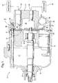
- Typical features of compressor 10 include a relatively massive main compressor body, basically a horizontal cylinder, with an internal crankcase 12 adjacent to a refrigerant manifold 14, the two separated by a valve plate 16. Most of the moving parts of compressor 10 are contained within crankcase 12, including reciprocating pistons 18 (moved by a non illustrated swash plate), drive shaft 20, and drive shaft support bearings 22.
- Valve plate 16 supports one way suction reed valves 24 that pass refrigerant vapor from a manifold suction chamber 26 to the pistons 18, and opposed one way discharge reed valves 27 that pass compressed refrigerant vapor from pistons 18 into a manifold discharge chamber 28.
- Both the suction chamber 26 and discharge chamber 28 are convoluted spaces, but the suction chamber is basically radially outboard relative to the manifold 14, and the discharge chamber 28 central, with each kept sealed from the other by a sealing gasket 30, clamped tightly between the outside of valve plate 16 and the inside of manifold 14.
- Several conventional through bolts 31 that clamp head 14 in place necessarily pass through valve plate 16 and gasket 30, a factor that is significant later in the description.
- a control valve cavity 32 contains a non illustrated control valve which provides for selective communication of vapor pressure between suction chamber 26 and the crankcase 12, so as to adjust a relative pressure balance between the vapor pressures acting on the front and rear of the pistons 18, thereby controlling their stroke.
- What is significant here is not the operation of the control valve per se, but rather the fact that it is located at a low point relative to the crankcase 12, and also that manifold 14 includes both a crankcase to valve cavity passage 34 and a valve suction chamber to valve cavity bleed orifice 36 that allow the refrigerant vapor flows necessary to the operation of the compressor 10.
- the centrally located discharge chamber 28 has a discharge port 38, which, significantly, is located above the valve cavity 32.
- Discharge port 38 is connected by conventional refrigerant lines to a condenser, indicated schematically at 40, which is mounted behind the vehicle grill, generally lower than the outlet port 38.
- Condenser 40 is exposed to lower directed, morning sun rays, but more shielded later in the day, and is relatively light weight, so that it both cools and warms relatively rapidly.
- the suction chamber 26 has an inlet port 42, located generally above discharge port 38, and connected by refrigerant lines to an evaporator, indicated schematically at 44.
- Evaporator 44 is located typically inside an HVAC housing that is at least partially inside the vehicle cabin, is exposed to the same greenhouse effect solar warming, and also capable or relatively rapid warming.
- compressor 10, condenser 40, and evaporator 44, as well as the internal structures of compressor 10 were found to contribute to the previously unappreciated lubricant migration phenomenon noted above.
- Lubricant that migrates to and is temporarily retained in the condenser 40 is not available at compressor start up, and will not re enter the system and the compressor fully until the system has been running for a time. As a consequence, a larger system charge of lubricant is required than would otherwise be necessary if the crankcase retention of lubricant during prolonged periods of system inactivity could be somehow improved.
- An obvious solution is the addition of a check valve in the refrigerant line between the discharge port 38 and the condenser 40. This would add cost and pressure drop to the system, however.
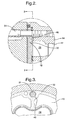
- the sealing gasket 30 referred to above has a simple notch 46 molded into it at the high point where the upper through bolt 31 passes through it. The operation of notch 46 is described next.
- the compressor is shown at a point in the mid afternoon, during a period of prolonged system inactivity, such as might occur when the vehicle sits in a parking lot for several days consecutively.
- gasket 30 having been provided with the notch 46 as described above, a small vapor flow passage is thereby created at a high point within crankcase12 into suction chamber 26. Being at a high point, vapor will reach it, but liquid will not, unlike the passages 34 and 36 at the lower location. Consequently, a pressure differential does not develop between crankcase 12 and suction chamber 14 to drive outflow of liquid from crankcase 12 into manifold 14. Instead, vapor is able to equalize between the two, and the liquid level remains the same in crankcase 12 and manifold 14.
Landscapes
- Engineering & Computer Science (AREA)
- Mechanical Engineering (AREA)
- General Engineering & Computer Science (AREA)
- Physics & Mathematics (AREA)
- Thermal Sciences (AREA)
- Compressor (AREA)
- Compressors, Vaccum Pumps And Other Relevant Systems (AREA)
Applications Claiming Priority (2)
| Application Number | Priority Date | Filing Date | Title |
|---|---|---|---|
| US874046 | 2004-06-22 | ||
| US10/874,046 US7645125B2 (en) | 2004-06-22 | 2004-06-22 | Refrigerant compressor with improved oil retention |
Publications (2)
| Publication Number | Publication Date |
|---|---|
| EP1609989A2 true EP1609989A2 (de) | 2005-12-28 |
| EP1609989A3 EP1609989A3 (de) | 2007-04-04 |
Family
ID=34979624
Family Applications (1)
| Application Number | Title | Priority Date | Filing Date |
|---|---|---|---|
| EP05076335A Withdrawn EP1609989A3 (de) | 2004-06-22 | 2005-06-08 | Kältemittelkompressor mit verbesserter Ölspeicherung |
Country Status (2)
| Country | Link |
|---|---|
| US (1) | US7645125B2 (de) |
| EP (1) | EP1609989A3 (de) |
Cited By (1)
| Publication number | Priority date | Publication date | Assignee | Title |
|---|---|---|---|---|
| US7520210B2 (en) | 2006-09-27 | 2009-04-21 | Visteon Global Technologies, Inc. | Oil separator for a fluid displacement apparatus |
Families Citing this family (4)
| Publication number | Priority date | Publication date | Assignee | Title |
|---|---|---|---|---|
| US8596080B2 (en) | 2010-05-27 | 2013-12-03 | Delphi Technologies, Inc. | Air conditioning system having an improved internal heat exchanger |
| JP2019007435A (ja) * | 2017-06-27 | 2019-01-17 | 株式会社ヴァレオジャパン | 可変容量斜板式圧縮機 |
| US11440376B2 (en) * | 2017-08-04 | 2022-09-13 | Tesla, Inc. | Technologies for manifolds |
| WO2025136044A1 (ko) * | 2023-12-20 | 2025-06-26 | 한온시스템 주식회사 | 냉매 매니폴드 및 이를 포함한 쿨링 모듈 |
Citations (1)
| Publication number | Priority date | Publication date | Assignee | Title |
|---|---|---|---|---|
| US3828942A (en) | 1972-04-27 | 1974-08-13 | R Young | Panel lifting device |
Family Cites Families (14)
| Publication number | Priority date | Publication date | Assignee | Title |
|---|---|---|---|---|
| US2093295A (en) * | 1934-02-23 | 1937-09-14 | Wilford H Teeter | Compressor |
| US2926894A (en) * | 1958-06-30 | 1960-03-01 | Acf Ind Inc | Combined fuel pump and carburetor |
| US3473730A (en) * | 1967-12-15 | 1969-10-21 | Copeland Refrigeration Corp | Oil retention and crankcase pressure control system for refrigerant compressors |
| US3838942A (en) * | 1971-07-30 | 1974-10-01 | Mitchell J Co | Refrigeration compressor |
| US5189886A (en) * | 1987-09-22 | 1993-03-02 | Sanden Corporation | Refrigerating system having a compressor with an internally and externally controlled variable displacement mechanism |
| JPH0338462Y2 (de) * | 1989-04-28 | 1991-08-14 | ||
| JPH1162823A (ja) * | 1997-08-08 | 1999-03-05 | Sanden Corp | 可変容量圧縮機 |
| JP2000199478A (ja) * | 1998-10-30 | 2000-07-18 | Toyota Autom Loom Works Ltd | 可変容量型圧縮機 |
| US6352416B1 (en) * | 1999-03-15 | 2002-03-05 | Kabushiki Kaisha Toyoda Jidoshokki Seisakusho | Device and method for controlling displacement of variable displacement compressor |
| JP2001221157A (ja) * | 2000-02-04 | 2001-08-17 | Toyota Autom Loom Works Ltd | 可変容量圧縮機 |
| US6568920B2 (en) * | 2001-08-21 | 2003-05-27 | Delphi Technologies, Inc. | Manifold assembly for a compressor |
| US6575708B2 (en) | 2001-09-13 | 2003-06-10 | Delphi Technologies, Inc. | Compressor head with improved oil retention |
| DE10218477A1 (de) * | 2002-04-25 | 2003-11-20 | Mahle Gmbh | Gekühlter zweiteiliger Kolben |
| US6877494B2 (en) * | 2002-07-12 | 2005-04-12 | Pearson Motor Company Limited | Lightweight four-stroke engine |
-
2004
- 2004-06-22 US US10/874,046 patent/US7645125B2/en not_active Expired - Fee Related
-
2005
- 2005-06-08 EP EP05076335A patent/EP1609989A3/de not_active Withdrawn
Patent Citations (1)
| Publication number | Priority date | Publication date | Assignee | Title |
|---|---|---|---|---|
| US3828942A (en) | 1972-04-27 | 1974-08-13 | R Young | Panel lifting device |
Cited By (1)
| Publication number | Priority date | Publication date | Assignee | Title |
|---|---|---|---|---|
| US7520210B2 (en) | 2006-09-27 | 2009-04-21 | Visteon Global Technologies, Inc. | Oil separator for a fluid displacement apparatus |
Also Published As
| Publication number | Publication date |
|---|---|
| EP1609989A3 (de) | 2007-04-04 |
| US20050281686A1 (en) | 2005-12-22 |
| US7645125B2 (en) | 2010-01-12 |
Similar Documents
| Publication | Publication Date | Title |
|---|---|---|
| US6237362B1 (en) | Internal oil separator for compressors of refrigeration systems | |
| US4478054A (en) | Helical screw rotary compressor for air conditioning system having improved oil management | |
| US20080232992A1 (en) | Fluid Machine | |
| US4403921A (en) | Multi-cylinder variable delivery compressor | |
| DE19633533C2 (de) | Taumelscheibenkompressor | |
| US5531078A (en) | Low volume inlet reciprocating compressor for dual evaporator refrigeration system | |
| US5159820A (en) | Oil separator integrally mounted on compressor | |
| US7645125B2 (en) | Refrigerant compressor with improved oil retention | |
| JPH1054215A (ja) | 内燃機関の潤滑回路における油圧制御装置 | |
| US8596080B2 (en) | Air conditioning system having an improved internal heat exchanger | |
| US4887514A (en) | Oil separation and gas pressure equalizer means for reciprocating gas compressor | |
| US4441863A (en) | Variable discharge rotary compressor | |
| KR20010059281A (ko) | 압축기 내장형 오일분리기 | |
| US4432702A (en) | Swash plate type compressor | |
| US8118566B2 (en) | Piston compressor with second intake | |
| US2863301A (en) | Lubricant circulation in refrigerating apparatus | |
| US7607897B2 (en) | Reciprocating compressor | |
| US3123287A (en) | figure | |
| JP3632448B2 (ja) | 圧縮機 | |
| US4487562A (en) | Rotary vane type compressor | |
| CN109882413A (zh) | 旋转式压缩机及具有其的制冷系统 | |
| FR2845432A1 (fr) | Compresseur a piston axial de co2 pour des installations de climatisation de vehicules automobiles | |
| US2818210A (en) | Refrigerating apparatus | |
| JPS63280876A (ja) | 斜板式圧縮機の潤滑機構 | |
| JPH07117320B2 (ja) | ターボ冷凍機の潤滑装置 |
Legal Events
| Date | Code | Title | Description |
|---|---|---|---|
| PUAI | Public reference made under article 153(3) epc to a published international application that has entered the european phase |
Free format text: ORIGINAL CODE: 0009012 |
|
| AK | Designated contracting states |
Kind code of ref document: A2 Designated state(s): AT BE BG CH CY CZ DE DK EE ES FI FR GB GR HU IE IS IT LI LT LU MC NL PL PT RO SE SI SK TR |
|
| AX | Request for extension of the european patent |
Extension state: AL BA HR LV MK YU |
|
| PUAL | Search report despatched |
Free format text: ORIGINAL CODE: 0009013 |
|
| AK | Designated contracting states |
Kind code of ref document: A3 Designated state(s): AT BE BG CH CY CZ DE DK EE ES FI FR GB GR HU IE IS IT LI LT LU MC NL PL PT RO SE SI SK TR |
|
| AX | Request for extension of the european patent |
Extension state: AL BA HR LV MK YU |
|
| RIC1 | Information provided on ipc code assigned before grant |
Ipc: F25B 31/00 20060101ALI20070227BHEP Ipc: F04B 27/10 20060101AFI20070227BHEP |
|
| 17P | Request for examination filed |
Effective date: 20071004 |
|
| 17Q | First examination report despatched |
Effective date: 20071031 |
|
| AKX | Designation fees paid |
Designated state(s): AT BE BG CH CY CZ DE DK EE ES FI FR GB GR HU IE IS IT LI LT LU MC NL PL PT RO SE SI SK TR |
|
| GRAP | Despatch of communication of intention to grant a patent |
Free format text: ORIGINAL CODE: EPIDOSNIGR1 |
|
| GRAC | Information related to communication of intention to grant a patent modified |
Free format text: ORIGINAL CODE: EPIDOSCIGR1 |
|
| STAA | Information on the status of an ep patent application or granted ep patent |
Free format text: STATUS: THE APPLICATION IS DEEMED TO BE WITHDRAWN |
|
| 18D | Application deemed to be withdrawn |
Effective date: 20100323 |