EP1609564A2 - Verfahren zum Ermitteln des Soll-Anzugsmoments - Google Patents
Verfahren zum Ermitteln des Soll-Anzugsmoments Download PDFInfo
- Publication number
- EP1609564A2 EP1609564A2 EP05010970A EP05010970A EP1609564A2 EP 1609564 A2 EP1609564 A2 EP 1609564A2 EP 05010970 A EP05010970 A EP 05010970A EP 05010970 A EP05010970 A EP 05010970A EP 1609564 A2 EP1609564 A2 EP 1609564A2
- Authority
- EP
- European Patent Office
- Prior art keywords
- component
- torque
- media
- remaining
- screw
- Prior art date
- Legal status (The legal status is an assumption and is not a legal conclusion. Google has not performed a legal analysis and makes no representation as to the accuracy of the status listed.)
- Withdrawn
Links
Images

Classifications
-
- G—PHYSICS
- G01—MEASURING; TESTING
- G01L—MEASURING FORCE, STRESS, TORQUE, WORK, MECHANICAL POWER, MECHANICAL EFFICIENCY, OR FLUID PRESSURE
- G01L5/00—Apparatus for, or methods of, measuring force, work, mechanical power, or torque, specially adapted for specific purposes
- G01L5/0028—Force sensors associated with force applying means
- G01L5/0042—Force sensors associated with force applying means applying a torque
-
- B—PERFORMING OPERATIONS; TRANSPORTING
- B23—MACHINE TOOLS; METAL-WORKING NOT OTHERWISE PROVIDED FOR
- B23P—METAL-WORKING NOT OTHERWISE PROVIDED FOR; COMBINED OPERATIONS; UNIVERSAL MACHINE TOOLS
- B23P19/00—Machines for simply fitting together or separating metal parts or objects, or metal and non-metal parts, whether or not involving some deformation; Tools or devices therefor so far as not provided for in other classes
- B23P19/04—Machines for simply fitting together or separating metal parts or objects, or metal and non-metal parts, whether or not involving some deformation; Tools or devices therefor so far as not provided for in other classes for assembling or disassembling parts
- B23P19/06—Screw or nut setting or loosening machines
- B23P19/065—Arrangements for torque limiters or torque indicators in screw or nut setting machines
-
- B—PERFORMING OPERATIONS; TRANSPORTING
- B25—HAND TOOLS; PORTABLE POWER-DRIVEN TOOLS; MANIPULATORS
- B25B—TOOLS OR BENCH DEVICES NOT OTHERWISE PROVIDED FOR, FOR FASTENING, CONNECTING, DISENGAGING, OR HOLDING
- B25B23/00—Details of, or accessories for, spanners, wrenches, screwdrivers
- B25B23/14—Arrangement of torque limiters or torque indicators in wrenches or screwdrivers
-
- G—PHYSICS
- G01—MEASURING; TESTING
- G01L—MEASURING FORCE, STRESS, TORQUE, WORK, MECHANICAL POWER, MECHANICAL EFFICIENCY, OR FLUID PRESSURE
- G01L5/00—Apparatus for, or methods of, measuring force, work, mechanical power, or torque, specially adapted for specific purposes
- G01L5/24—Apparatus for, or methods of, measuring force, work, mechanical power, or torque, specially adapted for specific purposes for determining value of torque or twisting moment for tightening a nut or other member which is similarly stressed
Definitions
- the invention relates to a device according to the preamble of FIG. Claim, a use of the method according to claim 5 and 6 and an apparatus for carrying out the method according to claim 7.
- the object of the present invention is a method and a device to provide for the implementation of the method with which the necessary Target tightening torque can be determined safely.
- the invention is based on the finding that the influences caused by the thread friction then be neglected when the component with the Internal thread is separated at its inner thread spout and then the force exerted by screwing in the screw, cap screw, etc. Force is measured on the separated component or when it reaches the predetermined contact force the associated torque is detected.
- the advantage of the invention is that all influences the material pairing screw - thread when determining the bolt force be left outside and only actually the applied bolt force is taken into account. This makes it possible, the screw tighten liquid-tight.
- the development according to claim 2 has the advantage that for each actually used screw the required nominal torque determined is, if both parts are original components, there depending upon manufacturer the Screw force at the same torque may be different.
- the rotation angle can also be measured according to claim 4 Be next to the tightening torque.
- the method according to the invention can then be applied particularly advantageously if with media-carrying lines in motor vehicles, the necessary Tightening torque is determined.
- a component with a External thread used a union nut, with which to a sealing bead shaped end of the media-carrying line to a coupling piece or a component is screwed liquid-tight.
- Claims 7 to 9 describe a preferred apparatus for performing the method according to the invention. This device is here simply made up of few components without being unreliable.
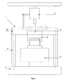
- the device 1 according to FIG. 1 consists of a U-shaped frame 2, which is attached to a base plate 3.
- a torque and rotation angle measuring device 7 arranged above the sample holder.
- the screwing point of a media-carrying line is used at a coupling point or on a component.
- the sample 8 has a piece of the media-carrying pipe 9 on.
- This media-leading line is - as is well known - on her End provided with a bead 10, which via a cap screw 11 in a coupling piece 12 is pressed sealingly.
- the media leading Cable is against twisting while tightening the cap screw 11 secured.
- the sample holder 6 has a shape adapted to the shape of the sample 8 Guide 13, in which the coupling piece 12 is used.
- the coupling piece 12 In the axial direction, the coupling piece 12 by a counter bearing 14th held.
- the anvil 14 has to approach the torque / rotation angle device 7 a corresponding recess, so that - via an adapter, not shown - the key attack surface of Cap screw 11 connected to the torque / rotation angle device 7 can be.
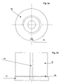
- Figure 3a is a plan view of the coupling piece 12 is shown. Here one clearly sees the longitudinal groove 15, which is not shown in detail Nose in the guide 13 cooperates and turning the coupling piece 12 prevented when screwing the cap screw 11.
- the coupling piece 12 Before the coupling piece 12 inserted into the guide 13 and the adapter 5 is, the coupling piece 12 is at the level of the inner thread spout perpendicular to the thread longitudinal direction by means of a parting line 16 cut so that a separated portion 17 and a remaining portion 18 remains.
- the separated portion 17 is in a corresponding Recording inserted into the adapter 5, while the remaining portion 18 is inserted into the guide 13 and by the anvil 14 against the severed portion 17 is pressed.
- this pump housing is a sample taken with the thread and according to the above explanations prepared and inserted into the sample holders.
- the method according to the invention is thus suitable both for screw forces in general to determine patterns as well as the real components, by the samples are taken from the real components.
- the inventive method can not only to determine the necessary screw force for producing a media-tight connection be used, but also to the studs the to determine the necessary tightening torque.
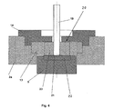
- FIG. Instead of the media-leading Line 9 and the cap screw 11 is now a threaded pin 19 used in the blind hole, such as a cylinder head or a crankcase, to be screwed. Accordingly, will taken at the screw from the component a sample 20, the receiving blind hole 21 contains.
- This sample piece 20 is analogous to the Coupling piece 12 in two sections 22, 23 at the level of the inner Spout shared, with the rest of the section again with a longitudinal groove is provided, in which engages the not shown nose of the guide 13.
- the separated section is as in the previous example in the adapter 5 of Tension and pressure measuring device inserted.
- the applied bolting is determined by that the grub screw is screwed into the sample 20 until it with its screwed end face on the severed portion 22 a before defined force exerts the tension and pressure measuring device 4 indicates.
Landscapes
- Physics & Mathematics (AREA)
- General Physics & Mathematics (AREA)
- Engineering & Computer Science (AREA)
- Mechanical Engineering (AREA)
- Chemical & Material Sciences (AREA)
- Analytical Chemistry (AREA)
- Force Measurement Appropriate To Specific Purposes (AREA)
Abstract
Description
- Figur 1
- eine schematisierte Ansicht der erfindungsgemäßen Vorrichtung;
- Figur 2
- ein Detail aus Figur 1;
- Figur 3a
- eine Draufsicht auf ein Innengewindestück;
- Figur 3b
- eine Seitenansicht des Innengewindestückes nach Figur 3a;
- Figur 4
- eine Detailansicht nach Figur 1 für ein alternatives Ausführungsbeispiel.
Claims (9)
- Verfahren zum Ermitteln des Soll-Anzugsmomentes von Schraubenverbindungen, bestehend aus einem ersten Bauteil mit Außengewinde (Schraube) und einem zweiten Bauteil mit Innengewinde (Mutternteil), wobei während des Verschraubens das aufgebrachte Drehmoment gemessen wird,
dadurch gekennzeichnet,dass das Bauteil mit Innengewinde am inneren Gewindeauslauf senkrecht zur Gewindelängsachse geteilt wird,dass das abgeteilte Bauteil in Kontakt mit dem Rest des zweiten Bauteiles gehalten wird unddass die auf das abgeteilte Bauteil ausgeübte Kraft beim Einschrauben des ersten Bauteils in das restliche zweite Bauteil gemessen wird. - Verfahren nach Anspruch 1,
dadurch gekennzeichnet, dass beide Bauteile Originalbauteile sind. - Verfahren nach Anspruch 1 oder 2,
dadurch gekennzeichnet, dass das restliche zweite Bauteil gegen Verdrehen während des Einschraubens des ersten Bauteils gesichert wird. - Verfahren nach einem der Ansprüche 1 bis 3,
dadurch gekennzeichnet, dass neben dem Drehmoment auch der Drehwinkel gemessen wird. - Verwendung des Verfahrens nach einem der Ansprüche 1 bis 4 zum Ermitteln des Soll-Anzugsmomentes von Überwurfschrauben (12) an medienführenden Leitungen (9) von Kraftfahrzeugen.
- Verwendung des Verfahrens nach einem der Ansprüche 1 bis 4 zum Ermitteln des Soll-Anzugsmomentes von in Sacklochbohrungen (21) einzuschraubenden Gewindestiften (19).
- Vorrichtung zur Durchführung des Verfahrens nach einem der Ansprüche 1 bis 6,
dadurch gekennzeichnet, dass ein Rahmen (2) vorgesehen ist, in dem das geteilte zweite Bauteil (12 bzw. 22, 23) zwischen einem Gegenlager und einer Kraftmesseinrichtung (4) eingespannt ist und dass eine Drehmomentmesseinrichtung (7) vorgesehen ist, die mit dem ersten Bauteil (11 bzw. 19) zusammenwirkt. - Vorrichtung nach Anspruch 7,
dadurch gekennzeichnet, dass restliche zweite Bauteil (12 bzw. 23) in eine Führung (13) eingesetzt ist. - Vorrichtung nach Anspruch 8,
dadurch gekennzeichnet, dass die Führung (13) eine Nase aufweist, die in eine an dem restlichen zweiten Bauteil (12 bzw. 23) vorgesehenen Längsnut (15) eingreift.
Applications Claiming Priority (2)
| Application Number | Priority Date | Filing Date | Title |
|---|---|---|---|
| DE200410030772 DE102004030772A1 (de) | 2004-06-25 | 2004-06-25 | Verfahren zum Ermitteln des Soll-Anzugsmomentes |
| DE102004030772 | 2004-06-25 |
Publications (2)
| Publication Number | Publication Date |
|---|---|
| EP1609564A2 true EP1609564A2 (de) | 2005-12-28 |
| EP1609564A3 EP1609564A3 (de) | 2008-12-10 |
Family
ID=35044590
Family Applications (1)
| Application Number | Title | Priority Date | Filing Date |
|---|---|---|---|
| EP05010970A Withdrawn EP1609564A3 (de) | 2004-06-25 | 2005-05-20 | Verfahren zum Ermitteln des Soll-Anzugsmoments |
Country Status (2)
| Country | Link |
|---|---|
| EP (1) | EP1609564A3 (de) |
| DE (1) | DE102004030772A1 (de) |
Cited By (1)
| Publication number | Priority date | Publication date | Assignee | Title |
|---|---|---|---|---|
| US8490500B2 (en) | 2010-11-16 | 2013-07-23 | Caterpillar Inc. | Torque coefficient measuring device |
Family Cites Families (4)
| Publication number | Priority date | Publication date | Assignee | Title |
|---|---|---|---|---|
| DE2521428C2 (de) * | 1975-05-14 | 1979-07-19 | Erichsen A M Gmbh | Meßgerät zur Bestimmung des Anzugsmomentes, des Kopf- und Gewindeanteils des Anzugsmomentes und der axialen Vorspannkraft eines Schraubenbolzens bzw. einer Schraubenverbindung |
| JPS59120839A (ja) * | 1982-12-27 | 1984-07-12 | Kawasaki Steel Corp | トルシヤ型ボルト試験機 |
| DE4309016C2 (de) * | 1993-03-20 | 1996-12-19 | Webasto Karosseriesysteme | Vorrichtung und Verfahren zum Ermitteln geeigneter Anzugsmomente für Schraubverbindungen mit selbstschneidenden Schrauben |
| DE50114947D1 (de) * | 2000-02-07 | 2009-08-06 | Kistler Holding Ag | Prüfgerät zur ermittlung der reib- und vorspannwerte von schraubenverbindungen |
-
2004
- 2004-06-25 DE DE200410030772 patent/DE102004030772A1/de not_active Withdrawn
-
2005
- 2005-05-20 EP EP05010970A patent/EP1609564A3/de not_active Withdrawn
Cited By (1)
| Publication number | Priority date | Publication date | Assignee | Title |
|---|---|---|---|---|
| US8490500B2 (en) | 2010-11-16 | 2013-07-23 | Caterpillar Inc. | Torque coefficient measuring device |
Also Published As
| Publication number | Publication date |
|---|---|
| DE102004030772A1 (de) | 2006-01-19 |
| EP1609564A3 (de) | 2008-12-10 |
Similar Documents
| Publication | Publication Date | Title |
|---|---|---|
| DE69618371T2 (de) | Verfahren und Vorrichtung zum Setzen von Blindnieten und dessen Überprüfung | |
| EP2346643B1 (de) | Schraubenspannvorrichtung | |
| DE112004000660B3 (de) | Steuerungsverfahren zur Steuerung des Betriebs eines Werkzeugs zum Setzen verformbarer Befestigungsmittel in ein Werkstück | |
| DE602004000304T2 (de) | Gesteuerter Schraubenschlüssel | |
| EP0459365A1 (de) | Befestigungsschraube | |
| EP2049307B1 (de) | Aggregat mit wenigstens zwei daran befestigter hydraulikanschlüsse | |
| DE102013110503A1 (de) | Entfernbare Sensoranschluss-Einsatzvorrichtung | |
| DE19819301C1 (de) | Verfahren und Vorrichtung zum Prüfen der Vorspannkraft von Schraubverbindungen | |
| DE19819300A1 (de) | Verfahren und Vorrichtung zum Herstellen und Prüfen von Schraubverbindungen | |
| DE602004000640T2 (de) | Montagestruktur und Verfahren zur Montage eines Bauteils in eine Struktur | |
| DE69525102T2 (de) | Vorrichtung zum Festhalten eines Messinstruments an einem Schraubenkopf | |
| DE112008001364B4 (de) | Verbinder für Fluiddruckvorrichtungen | |
| EP0935514A1 (de) | Verfahren zur herstellung von schraubverbindungen | |
| EP1609564A2 (de) | Verfahren zum Ermitteln des Soll-Anzugsmoments | |
| DE4100410C2 (de) | Verfahren zur Überwachung der Qualität einer Preßverbindung | |
| DE60209093T2 (de) | Befestigungselement | |
| EP3884254B1 (de) | Verfahren zur herstellung einer hochdruck-hydraulikleitung sowie radialpresse zur durchführung des verfahrens | |
| DE69326538T2 (de) | Zweiteilige Matrize zum Ausrüsten einer Einzieh- und/oder Crimppresse. | |
| DE112020006951T5 (de) | Verdrehsicherer rückhaltemechanismus für einen hochdruck-kraftstoffinjektor in einem kraftstoffsystem | |
| DE102010012207A1 (de) | Drosselschraube und hydraulisches Gerät | |
| DE102010037392B4 (de) | Bördelpresse für Fluidleitungen, Einstellhilfe für eine Bördelpresse und Verfahren zum Erzeugen einer Bördelung | |
| AT527227B1 (de) | Verbindungselement für schläuche, rohre oder andere fluidtransporteinrichtungen | |
| DE20301106U1 (de) | Vorrichtung zum Befestigen eines Beschleunigungsaufnehmers | |
| DE102017130337A1 (de) | Montagevorrichtung zum Einbringen eines Messelements in eine Ausnehmung eines Bauteils | |
| DE10063517A1 (de) | Abdrückstopfen für eine Rohrleitung |
Legal Events
| Date | Code | Title | Description |
|---|---|---|---|
| PUAI | Public reference made under article 153(3) epc to a published international application that has entered the european phase |
Free format text: ORIGINAL CODE: 0009012 |
|
| AK | Designated contracting states |
Kind code of ref document: A2 Designated state(s): AT BE BG CH CY CZ DE DK EE ES FI FR GB GR HU IE IS IT LI LT LU MC NL PL PT RO SE SI SK TR |
|
| AX | Request for extension of the european patent |
Extension state: AL BA HR LV MK YU |
|
| PUAL | Search report despatched |
Free format text: ORIGINAL CODE: 0009013 |
|
| AK | Designated contracting states |
Kind code of ref document: A3 Designated state(s): AT BE BG CH CY CZ DE DK EE ES FI FR GB GR HU IE IS IT LI LT LU MC NL PL PT RO SE SI SK TR |
|
| AX | Request for extension of the european patent |
Extension state: AL BA HR LV MK YU |
|
| RIC1 | Information provided on ipc code assigned before grant |
Ipc: G01L 5/24 20060101ALI20081106BHEP Ipc: B23P 19/06 20060101ALI20081106BHEP Ipc: B25B 23/14 20060101AFI20051013BHEP |
|
| 17P | Request for examination filed |
Effective date: 20090110 |
|
| AKX | Designation fees paid |
Designated state(s): DE FR GB IT |
|
| 17Q | First examination report despatched |
Effective date: 20100201 |
|
| RAP1 | Party data changed (applicant data changed or rights of an application transferred) |
Owner name: BAYERISCHE MOTOREN WERKE AKTIENGESELLSCHAFT |
|
| STAA | Information on the status of an ep patent application or granted ep patent |
Free format text: STATUS: THE APPLICATION IS DEEMED TO BE WITHDRAWN |
|
| 18D | Application deemed to be withdrawn |
Effective date: 20151201 |