EP1609508B1 - Emergency truck - Google Patents
Emergency truck Download PDFInfo
- Publication number
- EP1609508B1 EP1609508B1 EP03712146A EP03712146A EP1609508B1 EP 1609508 B1 EP1609508 B1 EP 1609508B1 EP 03712146 A EP03712146 A EP 03712146A EP 03712146 A EP03712146 A EP 03712146A EP 1609508 B1 EP1609508 B1 EP 1609508B1
- Authority
- EP
- European Patent Office
- Prior art keywords
- board
- module
- power supply
- pressure
- taps
- Prior art date
- Legal status (The legal status is an assumption and is not a legal conclusion. Google has not performed a legal analysis and makes no representation as to the accuracy of the status listed.)
- Expired - Lifetime
Links
- 238000005286 illumination Methods 0.000 claims abstract description 12
- XLYOFNOQVPJJNP-UHFFFAOYSA-N water Substances O XLYOFNOQVPJJNP-UHFFFAOYSA-N 0.000 claims abstract description 10
- 230000001276 controlling effect Effects 0.000 claims description 7
- 230000009977 dual effect Effects 0.000 claims description 4
- 230000001105 regulatory effect Effects 0.000 claims description 4
- 238000013021 overheating Methods 0.000 claims description 2
- 238000010248 power generation Methods 0.000 claims 1
- 238000000605 extraction Methods 0.000 abstract description 2
- 239000000463 material Substances 0.000 description 3
- QVGXLLKOCUKJST-UHFFFAOYSA-N atomic oxygen Chemical compound [O] QVGXLLKOCUKJST-UHFFFAOYSA-N 0.000 description 2
- 229910052760 oxygen Inorganic materials 0.000 description 2
- 239000001301 oxygen Substances 0.000 description 2
- 238000006424 Flood reaction Methods 0.000 description 1
- 238000004887 air purification Methods 0.000 description 1
- 230000000295 complement effect Effects 0.000 description 1
- 238000010276 construction Methods 0.000 description 1
- 230000005611 electricity Effects 0.000 description 1
- 239000012530 fluid Substances 0.000 description 1
- 238000009423 ventilation Methods 0.000 description 1
Images


Classifications
-
- B—PERFORMING OPERATIONS; TRANSPORTING
- B60—VEHICLES IN GENERAL
- B60P—VEHICLES ADAPTED FOR LOAD TRANSPORTATION OR TO TRANSPORT, TO CARRY, OR TO COMPRISE SPECIAL LOADS OR OBJECTS
- B60P3/00—Vehicles adapted to transport, to carry or to comprise special loads or objects
- B60P3/14—Vehicles adapted to transport, to carry or to comprise special loads or objects the object being a workshop for servicing, for maintenance, or for carrying workmen during work
-
- B—PERFORMING OPERATIONS; TRANSPORTING
- B60—VEHICLES IN GENERAL
- B60P—VEHICLES ADAPTED FOR LOAD TRANSPORTATION OR TO TRANSPORT, TO CARRY, OR TO COMPRISE SPECIAL LOADS OR OBJECTS
- B60P3/00—Vehicles adapted to transport, to carry or to comprise special loads or objects
-
- B—PERFORMING OPERATIONS; TRANSPORTING
- B62—LAND VEHICLES FOR TRAVELLING OTHERWISE THAN ON RAILS
- B62D—MOTOR VEHICLES; TRAILERS
- B62D33/00—Superstructures for load-carrying vehicles
- B62D33/04—Enclosed load compartments ; Frameworks for movable panels, tarpaulins or side curtains
- B62D33/042—Enclosed load compartments ; Frameworks for movable panels, tarpaulins or side curtains divided into compartments
-
- A—HUMAN NECESSITIES
- A62—LIFE-SAVING; FIRE-FIGHTING
- A62C—FIRE-FIGHTING
- A62C27/00—Fire-fighting land vehicles
Definitions
- the present invention relates to an emergency truck, from among vehicles designed and built for use in special emergency situations, the present vehicle being characterised by a design and configuration that make it suitable for use in situations requiring a combination of various resources.
- the present invention is characterised by the combination of the resources required to deal with the most varied situations which require the use of different resources such as electricity, water, pressure, illumination.
- the present invention lies in the field of motor vehicles designed to deal with various emergencies.
- vehicles intended for providing aid in emergency situations generally are able to deal with only one type of emergency, such as fire, floods or other.
- the pump is powered by the truck engine, causing it to overheat.
- the truck object of the invention is provided with a multiplier connected to the engine that prevents it from overheating.
- the object of the invention is to overcome the aforementioned disadvantages by developing a modular system for an emergency vehicle that covers practically any contingency which may occur.
- the object of the present invention of an emergency vehicle is a vehicle provided with a number of mutually connecting modules, disposed on a vehicle or truck so that with all modules assembled and connected to each other and secured on the bed of the truck it is possible to cover practically any contingency, as well as to provide assistance with almost any combination of resources as required.
- a generator module accessible from the side by vertically movable shutters; on the inside this module comprises an oil deposit, a 20 HP engine, a power transformer unit for supplying power to a battery power supply board and electrovalves for operating hydraulic pressure taps. It is also provided with electrical control and protection boards that control the operation of the shutters of the other modules, the voltage and overall power consumption of the system, the lights and the auxiliary services, providing tri-phasic and mono-phasic current connections for supplying power to any external equipment required.
- this last board is another panel with analogue pressure gauges. Specifically, these show the oil pressure in the 20 HP generator, the oil pressure in the cylinders, the water pressure in the rear pump and the oil pressure in the hydraulic pressure taps. It is also provided with a three-way valve, as well as a pressure regulator for all the pumps of the vehicle, which are a 27 litre, a 22 litre, a 16 litre and a 12 litre pump.
- Another module houses the air compressor, as well as leaving free space for housing any required tools or material. This module is only accessible from one of the sides.
- Another of the modules of the emergency vehicle object of the invention is one housing two water tanks. Together with the connections for the hoses provided in the adjacent module, these tanks allow emptying a well, garage or warehouse or suctioning with an external pump using the electrical connections for power supply.
- the last module connects with the previous one and is provided with a number of taps of various diameters and valves for opening and closing them. It is also provided with a deposit for storing and later distributing mashed food or sera, as well as allowing to supply air / oxygen. Additionally, it is provided with a number of quick-connectors of various diameters for changing the hose diameter.
- All of the modules can be secured to and slide on the truck platform by means of rails provided in the truck, and are connected to each other by mechanical and electrical connectors for supplying power to all of them and for supplying the various fluids.
- Figure 1 shows a general plan view of the truck with the various different modules comprising the vehicle, as well as the main equipment housed in each module.
- Figure 2 shows a side perspective view of the emergency vehicle showing the side access to the modules, as well as the illumination provided in them.
- Figure 3 shows an enlarged view of the electrical power supply control board.
- Figure 4 shows an enlarged view of the module with the pressure regulators and gauges (hydraulic / pneumatic).
- Figure 5 shows the control and protection board for the spotlights and the pump.
- Figure 6 shows a side view of the module providing access to the hose connections.
- Figure 7 shows the rear part of the module providing access to the hose connections.
- Figure 8 shows a side view of the current generation module, showing an oil tank, a 12V power supply board and the hydraulic pressure taps.
- Figure 9 shows the compressor.
- Figure 10 shows the 20 HP generator as well as a fan.
- FIG. 1 shows how the emergency truck comprises a number of interconnected modules secured on the bed of the truck.
- module (1) is the generator module that houses a 20 HP generator and the boards for controlling the electrical power supply and for controlling and regulating the pressure; also provided in this module are an oil deposit (12), a board (73) housing a transformer supplying power to a board (15) for the 12V power supply for battery recharging, as well as the power supply to the electrovalves controlling the hydraulic pressure taps, and a panel (11) housing the buttons and gauges of the pressure taps.
- the boards (5) and (6) which respectively are the electrical power supply control board and the control board for regulating and showing the pump pressure.
- the module (2) which houses a compressor (14), followed by the module (3), which houses two tanks (10) holding 1,000 litres each, and finally the module (4), which includes all access connections for the hoses (9) as well as the control and protection board for spotlights (7) and a pump board (8).
- Figure 2 shows that the vehicle or truck is provided with a number of lamps distributed along the top part of the cab and on the modules themselves; specifically, there is a pair of emergency lamps (17) on the front of the cab, and on the sides of the modules there are other swivelling lamps (16) for general illumination. On the top of the rear of the truck there is another emergency lamp (17) and another illumination lamp (16).
- the illumination lamps (16) are characterised by being motorised, so that their position can be determined with a selector.
- control and protection board (5) of the assembly and the board (6) for showing and controlling the regulation of the pump pressure. Visible in the rear module is the front panel of the control and protection board for power supply to the spotlights (7).
- FIG 3 shows the elements comprising the control and protection board (5) for the general power supply of the assembly, provided with a pair of switches (18), one voltmeter and ammeter set (20) to show the power supply voltage and the overall current consumption of the assembly, and other voltmeter and ammeter sets (21) and (22) for the power supply voltage and consumption of the illumination lamps and the auxiliary services respectively.
- the auxiliary services consist of the battery charger and the power supply for the electrovalves of the hydraulic pressure taps.
- Said board (5) is also provided with switches (23) for raising and lowering the module shutters.
- a dual on/off switch (26) for the general pump Included in said board are four switches (24, 25, 33 and 34).
- the switch (34) is for control and protection of the external lamps; the switch (25) is for control and protection of a fan placed next to a transformer for power supply to the external spotlights, placed behind the panel (7) ( figure 5 ).
- the switches (33) and (34) are for supplying power to the board (15), which houses the board (13) for recharging the batteries and the electrovalves of the pressure taps. Finally, it is provided with a tri-phasic power connection and a mono-phasic power connection.
- Figure 4 shows the panel (6) placed beneath the board (5) ( figure 3 ), where it can be seen to comprise an idling potentiometer (29), a thermostat (30), a pneumatic regulator (31) and a seal (32) for opening the general oil valve.
- the thermostat (30) is regulated so that if the temperature of 30°C is exceeded in the transformer powering the control panel (7) of the external spotlights (16), the fan (70) ( figure 10 ) of the 20 hp generator is turned on.
- the pressure gauges (39, 40, 41 and 42), of which indicators (39) show the oil pressure in the 20 HP generator (13), indicators (40) show the air pressure for opening the valve that controls the inlet of oil in the pumps, the gauge (41) shows the water pressure in the rear pump and the gauges (42) show the oil pressure in the 16 litre and 12 litre hydraulic taps.
- a number of couples are provided comprised of a three-way valve and pressure regulators (35, 36, 37, 38) for the 27 litre, 24 litre, 16 litre and 12 litre pumps respectively.
- the three-way valves When the three-way valves are actuated they send the oil to the generator instead of to the oil tank (13).
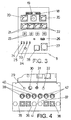
- FIG. 5 shows the component elements of the control panel for the spotlights (7) located on the rear module (4).
- This panel (7) is provided with a number of switches (43) for control and protection of the pump, a number of magnetothermal switches (44) for control and protection of each spotlight (16) ( figure 2 ), and a voltmeter and ammeter set (45) for showing the power supply and consumption of the pump of the truck in the rear module, next to which are installed the spotlight orientation switches (46), as these are motorised to allow their orientation; in addition, it is also provided with an on / off switch (49) for the pump provided in the module (4). Finally, it is provided with a tri-phasic current connection (48), two mono-phasic current connections at 220 V (50) and one mono-phasic current connection at 125 V (51).
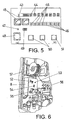
- Figure 6 also shows a side view of the last module (4), revealing the control board (8) of a pump with an on / off dual switch (52), an operation indicator lamp (53), a tri-phasic current connection (55) and one mono-phasic current connection at 220 V (56). Immediately above this is provided a connection hose (57).
- Figure 7 shows the assembly of connections for the hoses (9), as well as two hose reels (57) on either side of the module (4); beneath this are two one-inch taps (58) and two 1 1 ⁇ 2 inch taps (59), under which there are valves (60) for opening and closing the outlet of air/water. On the other side it has a 2 1 ⁇ 2 inch tap (61), three 1 1 ⁇ 2 inch taps (62) and a container for mashed food (63). On the base of the module are set a number of fast connectors (71) for changing the hose diameter.
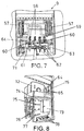
- FIG 8 shows the other side of the module (1), revealing the oil tank (12) on the top of the assembly, adjacent to which is an electrical power supply board (15) for charging batteries, provided with a number of 12 V connections (64) and other also 12 V connections requiring the connectors (65).
- Beneath said board (15) is a board (73) housing a power supply transformer for the battery-recharging board (13), which provides power to electrovalves for operating the pressure taps (78).
- the board (73) is placed on a panel (11) including the gauges and controls of the taps (78). Specifically, there are two power switches (74), one for each pair of hydraulic pressure taps (78); beneath this are four indicators (75) showing the operation of the pressure taps, of which the first and second show the automatic or manual operation of the first pair of pressure taps respectively, while the third and fourth show the automatic or manual operation of the second pair of pressure taps. On the bottom row is a pair of buttons (76) for choosing manual or automatic operation, and finally the last row comprises four buttons (77), of which the first two select the impulsion/return of the first pair of pressure taps while the other two are for controlling the impulsion/return of the second pair of taps; all of this can be performed using a remote control device.
- Figure 9 shows the module (2) housing the compressor (14), with a free space (72) provided in said module.
- FIG 10 shows the 20 HP generator (13) above which is the fan (70) for forced ventilation when required.
Abstract
Description
- The present invention relates to an emergency truck, from among vehicles designed and built for use in special emergency situations, the present vehicle being characterised by a design and configuration that make it suitable for use in situations requiring a combination of various resources.
- The present invention is characterised by the combination of the resources required to deal with the most varied situations which require the use of different resources such as electricity, water, pressure, illumination.
- Thus, the present invention lies in the field of motor vehicles designed to deal with various emergencies.
- Hitherto, vehicles intended for providing aid in emergency situations generally are able to deal with only one type of emergency, such as fire, floods or other.
- The problem generally facing such vehicles is the material impossibility of dealing with the many different situations occurring in catastrophes, which require the use of different resources. For this reason, trucks with a modular configuration have been developed, as shown in
DE 196 21 472 A1 orFR 2 564 410 A1 - Situations arise where it is necessary to have not only water tanks to extinguish fires, but also swivelling lamps and current generators, as on occasions it is necessary to provide electrical power to auxiliary field equipment, such as extraction pumps or oxygen supply or air purification equipment.
- Furthermore, in an emergency truck the pump is powered by the truck engine, causing it to overheat. In order to avoid this problem the truck object of the invention is provided with a multiplier connected to the engine that prevents it from overheating.
- There is no vehicle currently available in the market that offers such a combination of resources to provide assistance in emergency situations. Moreover, were one to be built including all resources it would be a compact unit, without providing a modular construction, for which
GB 2 158 783 A - In view of this, the object of the invention is to overcome the aforementioned disadvantages by developing a modular system for an emergency vehicle that covers practically any contingency which may occur.
- The object of the present invention of an emergency vehicle is a vehicle provided with a number of mutually connecting modules, disposed on a vehicle or truck so that with all modules assembled and connected to each other and secured on the bed of the truck it is possible to cover practically any contingency, as well as to provide assistance with almost any combination of resources as required.
- For this purpose, it is provided with a generator module accessible from the side by vertically movable shutters; on the inside this module comprises an oil deposit, a 20 HP engine, a power transformer unit for supplying power to a battery power supply board and electrovalves for operating hydraulic pressure taps. It is also provided with electrical control and protection boards that control the operation of the shutters of the other modules, the voltage and overall power consumption of the system, the lights and the auxiliary services, providing tri-phasic and mono-phasic current connections for supplying power to any external equipment required.
- Immediately beneath this last board is another panel with analogue pressure gauges. Specifically, these show the oil pressure in the 20 HP generator, the oil pressure in the cylinders, the water pressure in the rear pump and the oil pressure in the hydraulic pressure taps. It is also provided with a three-way valve, as well as a pressure regulator for all the pumps of the vehicle, which are a 27 litre, a 22 litre, a 16 litre and a 12 litre pump.
- Another module houses the air compressor, as well as leaving free space for housing any required tools or material. This module is only accessible from one of the sides.
- Another of the modules of the emergency vehicle object of the invention is one housing two water tanks. Together with the connections for the hoses provided in the adjacent module, these tanks allow emptying a well, garage or warehouse or suctioning with an external pump using the electrical connections for power supply.
- The last module connects with the previous one and is provided with a number of taps of various diameters and valves for opening and closing them. It is also provided with a deposit for storing and later distributing mashed food or sera, as well as allowing to supply air / oxygen. Additionally, it is provided with a number of quick-connectors of various diameters for changing the hose diameter.
- All of the modules can be secured to and slide on the truck platform by means of rails provided in the truck, and are connected to each other by mechanical and electrical connectors for supplying power to all of them and for supplying the various fluids.
- As a complement of the description being made and in order to aid a better understanding of its characteristics, the present descriptive memory is accompanied by a set of drawings with figures where, for purposes of illustration only and in a non-limiting manner the more relevant details of the invention are shown.
-
Figure 1 shows a general plan view of the truck with the various different modules comprising the vehicle, as well as the main equipment housed in each module. -
Figure 2 shows a side perspective view of the emergency vehicle showing the side access to the modules, as well as the illumination provided in them. -
Figure 3 shows an enlarged view of the electrical power supply control board. -
Figure 4 shows an enlarged view of the module with the pressure regulators and gauges (hydraulic / pneumatic). -
Figure 5 shows the control and protection board for the spotlights and the pump. -
Figure 6 shows a side view of the module providing access to the hose connections. -
Figure 7 shows the rear part of the module providing access to the hose connections. -
Figure 8 shows a side view of the current generation module, showing an oil tank, a 12V power supply board and the hydraulic pressure taps. -
Figure 9 shows the compressor. -
Figure 10 shows the 20 HP generator as well as a fan. - In view of the above described figures, a preferred embodiment of the invention is described hereunder with an explanation of the drawings.
-
Figure 1 shows how the emergency truck comprises a number of interconnected modules secured on the bed of the truck. Specifically, there are four modules where module (1) is the generator module that houses a 20 HP generator and the boards for controlling the electrical power supply and for controlling and regulating the pressure; also provided in this module are an oil deposit (12), a board (73) housing a transformer supplying power to a board (15) for the 12V power supply for battery recharging, as well as the power supply to the electrovalves controlling the hydraulic pressure taps, and a panel (11) housing the buttons and gauges of the pressure taps. Also housed on the other side are the boards (5) and (6), which respectively are the electrical power supply control board and the control board for regulating and showing the pump pressure. - After said first generator module (1) is disposed the module (2), which houses a compressor (14), followed by the module (3), which houses two tanks (10) holding 1,000 litres each, and finally the module (4), which includes all access connections for the hoses (9) as well as the control and protection board for spotlights (7) and a pump board (8).
-
Figure 2 shows that the vehicle or truck is provided with a number of lamps distributed along the top part of the cab and on the modules themselves; specifically, there is a pair of emergency lamps (17) on the front of the cab, and on the sides of the modules there are other swivelling lamps (16) for general illumination. On the top of the rear of the truck there is another emergency lamp (17) and another illumination lamp (16). The illumination lamps (16) are characterised by being motorised, so that their position can be determined with a selector. - Also shown are the general control and protection board (5) of the assembly and the board (6) for showing and controlling the regulation of the pump pressure. Visible in the rear module is the front panel of the control and protection board for power supply to the spotlights (7).
-
Figure 3 shows the elements comprising the control and protection board (5) for the general power supply of the assembly, provided with a pair of switches (18), one voltmeter and ammeter set (20) to show the power supply voltage and the overall current consumption of the assembly, and other voltmeter and ammeter sets (21) and (22) for the power supply voltage and consumption of the illumination lamps and the auxiliary services respectively. The auxiliary services consist of the battery charger and the power supply for the electrovalves of the hydraulic pressure taps. Said board (5) is also provided with switches (23) for raising and lowering the module shutters. In addition, it is provided with a dual on/off switch (26) for the general pump. Included in said board are four switches (24, 25, 33 and 34). The switch (34) is for control and protection of the external lamps; the switch (25) is for control and protection of a fan placed next to a transformer for power supply to the external spotlights, placed behind the panel (7) (figure 5 ). The switches (33) and (34) are for supplying power to the board (15), which houses the board (13) for recharging the batteries and the electrovalves of the pressure taps. Finally, it is provided with a tri-phasic power connection and a mono-phasic power connection. -
Figure 4 shows the panel (6) placed beneath the board (5) (figure 3 ), where it can be seen to comprise an idling potentiometer (29), a thermostat (30), a pneumatic regulator (31) and a seal (32) for opening the general oil valve. - The thermostat (30) is regulated so that if the temperature of 30°C is exceeded in the transformer powering the control panel (7) of the external spotlights (16), the fan (70) (
figure 10 ) of the 20 hp generator is turned on. - Beneath these controls are placed the pressure gauges (39, 40, 41 and 42), of which indicators (39) show the oil pressure in the 20 HP generator (13), indicators (40) show the air pressure for opening the valve that controls the inlet of oil in the pumps, the gauge (41) shows the water pressure in the rear pump and the gauges (42) show the oil pressure in the 16 litre and 12 litre hydraulic taps.
- Finally, a number of couples are provided comprised of a three-way valve and pressure regulators (35, 36, 37, 38) for the 27 litre, 24 litre, 16 litre and 12 litre pumps respectively. When the three-way valves are actuated they send the oil to the generator instead of to the oil tank (13).
-
Figure 5 shows the component elements of the control panel for the spotlights (7) located on the rear module (4). This panel (7) is provided with a number of switches (43) for control and protection of the pump, a number of magnetothermal switches (44) for control and protection of each spotlight (16) (figure 2 ), and a voltmeter and ammeter set (45) for showing the power supply and consumption of the pump of the truck in the rear module, next to which are installed the spotlight orientation switches (46), as these are motorised to allow their orientation; in addition, it is also provided with an on / off switch (49) for the pump provided in the module (4). Finally, it is provided with a tri-phasic current connection (48), two mono-phasic current connections at 220 V (50) and one mono-phasic current connection at 125 V (51). -
Figure 6 also shows a side view of the last module (4), revealing the control board (8) of a pump with an on / off dual switch (52), an operation indicator lamp (53), a tri-phasic current connection (55) and one mono-phasic current connection at 220 V (56). Immediately above this is provided a connection hose (57). -
Figure 7 shows the assembly of connections for the hoses (9), as well as two hose reels (57) on either side of the module (4); beneath this are two one-inch taps (58) and two 1 ½ inch taps (59), under which there are valves (60) for opening and closing the outlet of air/water. On the other side it has a 2 ½ inch tap (61), three 1 ½ inch taps (62) and a container for mashed food (63). On the base of the module are set a number of fast connectors (71) for changing the hose diameter. -
Figure 8 shows the other side of the module (1), revealing the oil tank (12) on the top of the assembly, adjacent to which is an electrical power supply board (15) for charging batteries, provided with a number of 12 V connections (64) and other also 12 V connections requiring the connectors (65). Beneath said board (15) is a board (73) housing a power supply transformer for the battery-recharging board (13), which provides power to electrovalves for operating the pressure taps (78). - The board (73) is placed on a panel (11) including the gauges and controls of the taps (78). Specifically, there are two power switches (74), one for each pair of hydraulic pressure taps (78); beneath this are four indicators (75) showing the operation of the pressure taps, of which the first and second show the automatic or manual operation of the first pair of pressure taps respectively, while the third and fourth show the automatic or manual operation of the second pair of pressure taps. On the bottom row is a pair of buttons (76) for choosing manual or automatic operation, and finally the last row comprises four buttons (77), of which the first two select the impulsion/return of the first pair of pressure taps while the other two are for controlling the impulsion/return of the second pair of taps; all of this can be performed using a remote control device.
-
Figure 9 shows the module (2) housing the compressor (14), with a free space (72) provided in said module. -
Figure 10 shows the 20 HP generator (13) above which is the fan (70) for forced ventilation when required. - It is not considered necessary to extend this description for an expert in the field to understand its scope and the advantages derived thereof.
- The materials, shape, size and arrangement of the component elements may vary as long as the essence of the invention, as defined by the claims, is not changed.
- The terms used in this descriptive memory shall be understood in a wide and non-limiting sense.
Claims (10)
- Emergency truck, which comprises a number of modules that can be connected to each other and are secured on the bed of the truck, allowing the use of combined resources regardless of the emergency situation which may arise, characterized in that is provided with a generator module (1), a module (2) housing a compressor (14), another module (3) housing two water tanks (10) and finally a module (4) with the hose-connection taps (9) and a control panel for illumination with spotlights; wherein the generator module (1) is provided with a board (5) for control and protection of the entire power generation of the unit, another board (6) for controlling the regulation and indication of the pump pressure, and on the other side it is provided with a board (15) for a 12 V power supply and a control panel (11) for the pressure taps (78), both of these being powered from a board (73) housing a transformer; internally provided is an oil deposit (12) beneath which are housed a 20 HP generator (13) and a fan (70); it is also provided with an emergency lamp and external illumination system; the access to the inside of the modules is achieved by means of shutters; in addition, it is provided with a multiplier connected between the engine and the pump, intended to prevent the truck engine from overheating.
- Emergency truck according to claim 1, characterised in that the illumination system comprises two emergency lamps (17) placed on the top of the front of the cab and an emergency light (17) on the rear of the last module, while the illumination system comprises a set of motorised swivelling lamps (16) controlled from a distance and disposed on the top of the truck.
- Emergency truck according to claim 1, characterised in that the control and protection board (5) for the overall power supply for the system comprises a set of switches (18), a voltmeter and ammeter set (20) for showing the power supply voltage and the overall current consumption of the assembly, and other voltmeter and ammeter sets (21) and (22) for showing the power supply voltage and consumption of the illumination lamps and the auxiliary services respectively, wherein the auxiliary services are the power supply to the 12V power supply board (15), as well as the power supply to the electrovalves of the pressure tap (78); it is also provided with switches (23) for raising and lowering the module shutters; in addition, it has a dual on / off switch (26) for a pump; also provided in said board are four switches (24, 25, 33 and 34): the switch (34) is for control and protection of the external lamps; the switch (25) is for control and protection of a fan located next to a transformer for power supply to the external spotlights, placed behind the panel (7) and the switches (33) and (34) are for power supply to the board (15).
- Emergency truck according to claim 1, characterised in that the panel (6) is provided with an idling potentiometer (29), a thermostat (30), a pneumatic regulator (31), a seal (32) for opening the valve of the general oil; beneath these controls are disposed pressure gauges (39), 40, 41 and 42), where the gauges (39) show the oil pressure in the 20 HP generator (13), the gauges (40) show the air pressure for opening the valve that controls the inlet of oil in the pumps, the gauge (41) shows the water pressure in the rear pump and the gauges (42) show the oil pressure in the 16 litre and 12 litre hydraulic connections; finally, a number of couples are provided comprised of a three-way valve and pressure regulators (35, 36, 37, 38) for the 27 litre, 24 litre, 16 litre and 12 litre pumps respectively; when these three-way valves are actuated they send the oil to the generator instead of to the oil tank (13).
- Emergency truck according to claim 1, characterised in that the control panel (7) for the spotlights is provided with a set of switches (43) for control and protection of the pump, a set of magnetothermal switches (44) for control and protection of each spotlight (16), as well as a voltmeter and ammeter set (45) for showing the power supply and consumption of the pump of the truck in the rear module, next to which are installed the spotlight orientation switches (46), as these are motorised to allow their orientation; in addition, it is also provided with an on / off switch (49) for the pump; it is also provided with an on / off switch (49) for the pump and an indicator (47) of the operation status of the pump in module (4).
- Emergency truck according to claim 1, characterised in that above the module (4) is a control board (8) for a pump, said board having a dual on/off switch (52), an operation status indicator lamp (53), a tri-phasic current connection (55) and a 220V mono-phasic current connection (56).
- Emergency truck according to claim 1, characterised in that the set of connections for the hoses (9) has two reels for the hoses (57) placed on either side of said module (4), beneath these are two one-inch taps (58) and two 1½ inch taps (59), beneath which are valves (60) for opening and closing the outlet of air/water; in addition it has a 2 ½ inch tap (61) and three 1½ inch taps (62) as well as a container for mashed food (63); on the base of the module are a number of fast connectors (71) for changing the hose diameter.
- Emergency truck according to claim 1, characterised in that the module (1) is provided with a 12V electrical power supply board (15) for charging the batteries, with a number of 12 V connections (64) and other 12 V connections where connection is established with connectors (65), also at 12V; beneath said board (15) is a board (73) housing a power supply transformer for the battery-recharging board (15), which supplies power to the electrovalves for operating the pressure taps (78).
- Emergency truck according to claim 8, characterised in that the operation of the pressure taps is controlled by a panel (11) housing the gauges and controls of said taps (78) having two power switches (74), one for each pair of pressure taps (78); beneath these are disposed four indicators (75) showing the operation status of the pressure taps, where the first and second show the automatic / manual operation of the first pair of pressure taps respectively, and the third and fourth show the automatic / manual operation of the second pair of pressure taps respectively; on the bottom row is a pair of buttons (76) for choosing between automatic or manual operation, and finally the last row comprises four buttons (77), of which the first two select the impulsion/return of the first pair of pressure taps while the other two are for controlling the impulsion/return of the second pair of taps; all of this can be controlled with a remote control device.
- Emergency truck according to claim 4, characterised in that the thermostat (30) is regulated so that if a temperature of 70 degrees is exceeded in the transformer for power supply to the control panel (7) of the external spotlights (16), the fan (70) of the 20 HP generator (13) is turned on.
Applications Claiming Priority (1)
| Application Number | Priority Date | Filing Date | Title |
|---|---|---|---|
| PCT/ES2003/000149 WO2004087261A1 (en) | 2003-04-02 | 2003-04-02 | Emergency truck |
Publications (2)
| Publication Number | Publication Date |
|---|---|
| EP1609508A1 EP1609508A1 (en) | 2005-12-28 |
| EP1609508B1 true EP1609508B1 (en) | 2008-06-18 |
Family
ID=33104260
Family Applications (1)
| Application Number | Title | Priority Date | Filing Date |
|---|---|---|---|
| EP03712146A Expired - Lifetime EP1609508B1 (en) | 2003-04-02 | 2003-04-02 | Emergency truck |
Country Status (6)
| Country | Link |
|---|---|
| EP (1) | EP1609508B1 (en) |
| AT (1) | ATE398479T1 (en) |
| DE (1) | DE60321725D1 (en) |
| ES (1) | ES2305450T3 (en) |
| PT (1) | PT1609508E (en) |
| WO (1) | WO2004087261A1 (en) |
Cited By (2)
| Publication number | Priority date | Publication date | Assignee | Title |
|---|---|---|---|---|
| WO2011075756A1 (en) | 2009-12-21 | 2011-06-30 | Rosenbauer International Aktiengesellschaft | Lighting module for an emergency service vehicle |
| RU2481205C1 (en) * | 2011-12-07 | 2013-05-10 | Открытое акционерное общество "Завод им. В.А. Дегтярева" | Mobile check-and-test complex |
Families Citing this family (4)
| Publication number | Priority date | Publication date | Assignee | Title |
|---|---|---|---|---|
| CN102451534A (en) * | 2010-11-01 | 2012-05-16 | 江苏卡威专用汽车制造有限公司 | Electrically-controlled maneuvering platform device for turbojet fire truck |
| DE102011050744B3 (en) * | 2011-05-31 | 2012-06-14 | 123-Engineering Ltd. & Co. Kg | Arrangement and method for the emergency supply of a nuclear installation |
| CN102390312A (en) * | 2011-09-17 | 2012-03-28 | 重庆全冠机电设备制造有限公司 | Diesel power generating set multifunctional mobile emergency engineering vehicle |
| US9663344B2 (en) | 2015-01-05 | 2017-05-30 | Neal Antero MAKKONEN | Apparatus for hazardous-fluid delivery vehicle and storage tank |
Family Cites Families (8)
| Publication number | Priority date | Publication date | Assignee | Title |
|---|---|---|---|---|
| US3770060A (en) * | 1972-12-26 | 1973-11-06 | Lockheed Aircraft Corp | Modular firefighting unit |
| GB2158783B (en) * | 1984-03-30 | 1988-06-22 | Grummet Australia Pty Ltd | Vehicle and method of construction thereof |
| ATA164484A (en) * | 1984-05-18 | 1987-11-15 | Rosenbauer Kg Konrad | EMERGENCY VEHICLE |
| AT385900B (en) * | 1984-05-18 | 1988-05-25 | Rosenbauer Kg Konrad | EMERGENCY VEHICLE, IN PARTICULAR FIREFIGHTER VEHICLE |
| AT394138B (en) * | 1987-11-06 | 1992-02-10 | Rosenbauer Int Gmbh | FIREFIGHTER VEHICLE WITH AN EQUIPMENT CAB |
| US5467827A (en) * | 1993-09-20 | 1995-11-21 | Mcloughlin; John E. | Modular fire truck |
| AT406573B (en) * | 1994-04-13 | 2000-06-26 | Rosenbauer Int Ag | SELF-SUPPORTING BOX ASSEMBLY FOR REPLACEMENT VEHICLES, IN PARTICULAR FIREFIGHTER VEHICLES |
| DE19621472A1 (en) * | 1996-05-29 | 1997-12-04 | Ziegler Albert Gmbh Co Kg | Emergency services vehicle esp. a fire service vehicle |
-
2003
- 2003-04-02 DE DE60321725T patent/DE60321725D1/en not_active Expired - Fee Related
- 2003-04-02 ES ES03712146T patent/ES2305450T3/en not_active Expired - Lifetime
- 2003-04-02 WO PCT/ES2003/000149 patent/WO2004087261A1/en active IP Right Grant
- 2003-04-02 EP EP03712146A patent/EP1609508B1/en not_active Expired - Lifetime
- 2003-04-02 AT AT03712146T patent/ATE398479T1/en not_active IP Right Cessation
- 2003-04-02 PT PT03712146T patent/PT1609508E/en unknown
Cited By (2)
| Publication number | Priority date | Publication date | Assignee | Title |
|---|---|---|---|---|
| WO2011075756A1 (en) | 2009-12-21 | 2011-06-30 | Rosenbauer International Aktiengesellschaft | Lighting module for an emergency service vehicle |
| RU2481205C1 (en) * | 2011-12-07 | 2013-05-10 | Открытое акционерное общество "Завод им. В.А. Дегтярева" | Mobile check-and-test complex |
Also Published As
| Publication number | Publication date |
|---|---|
| DE60321725D1 (en) | 2008-07-31 |
| ES2305450T3 (en) | 2008-11-01 |
| WO2004087261A1 (en) | 2004-10-14 |
| EP1609508A1 (en) | 2005-12-28 |
| ATE398479T1 (en) | 2008-07-15 |
| PT1609508E (en) | 2008-07-28 |
Similar Documents
| Publication | Publication Date | Title |
|---|---|---|
| US8013567B2 (en) | Portable power and utility system | |
| US5678982A (en) | Portable hydraulic system | |
| EP1609508B1 (en) | Emergency truck | |
| US20070087241A1 (en) | Fuel cell power pack | |
| RU2436995C2 (en) | Controller of feed | |
| US20170070065A1 (en) | Dc-powered system for controlling an air compressor or hydraulic fluid pump | |
| US6857478B1 (en) | Packaged residential fire sprinkler system | |
| MX2013001075A (en) | Operator interface for hydraulic tool control. | |
| US20210021139A1 (en) | Multi-voltage portable power system | |
| JP2013053833A (en) | Storage type water heater | |
| US4375162A (en) | Portable air test kit and system | |
| US6942468B2 (en) | Portable hydraulic pump unit | |
| EP1512433A2 (en) | Oxygen supply and distribution system for a passenger aircraft | |
| EP2470398B1 (en) | Utilities pod for caravans | |
| ES2309716T3 (en) | AN AUTONOMOUS CABIN. | |
| JP2018044760A (en) | Simple water heater | |
| JP2005524371A (en) | Distribution board | |
| CN107176081A (en) | A kind of medical shop-on-wheel | |
| CN208364898U (en) | A kind of electrically operated valve control circuit for refrigeration station of data center | |
| JP3019649U (en) | Uninterruptible valve operation panel | |
| CN211893101U (en) | Vehicle frame type centralized control equipment and movable dining car | |
| GB2493694A (en) | DC power supply comprising switch gear enabling parallel or series connection of batteries | |
| CN212225468U (en) | Amphibious hydraulic electric pump | |
| CN220821780U (en) | Emergency power supply type household storage device | |
| CA2546544A1 (en) | Fuel cell power pack |
Legal Events
| Date | Code | Title | Description |
|---|---|---|---|
| PUAI | Public reference made under article 153(3) epc to a published international application that has entered the european phase |
Free format text: ORIGINAL CODE: 0009012 |
|
| 17P | Request for examination filed |
Effective date: 20050729 |
|
| AK | Designated contracting states |
Kind code of ref document: A1 Designated state(s): AT BE BG CH CY CZ DE DK EE ES FI FR GB GR HU IE IT LI LU MC NL PT SE SI SK TR |
|
| GRAP | Despatch of communication of intention to grant a patent |
Free format text: ORIGINAL CODE: EPIDOSNIGR1 |
|
| GRAS | Grant fee paid |
Free format text: ORIGINAL CODE: EPIDOSNIGR3 |
|
| GRAA | (expected) grant |
Free format text: ORIGINAL CODE: 0009210 |
|
| AK | Designated contracting states |
Kind code of ref document: B1 Designated state(s): AT BE BG CH CY CZ DE DK EE ES FI FR GB GR HU IE IT LI LU MC NL PT SE SI SK TR |
|
| REG | Reference to a national code |
Ref country code: GB Ref legal event code: FG4D |
|
| REG | Reference to a national code |
Ref country code: PT Ref legal event code: SC4A Free format text: AVAILABILITY OF NATIONAL TRANSLATION Effective date: 20080717 |
|
| REF | Corresponds to: |
Ref document number: 60321725 Country of ref document: DE Date of ref document: 20080731 Kind code of ref document: P |
|
| REG | Reference to a national code |
Ref country code: CH Ref legal event code: EP |
|
| REG | Reference to a national code |
Ref country code: IE Ref legal event code: FG4D |
|
| PG25 | Lapsed in a contracting state [announced via postgrant information from national office to epo] |
Ref country code: SI Free format text: LAPSE BECAUSE OF FAILURE TO SUBMIT A TRANSLATION OF THE DESCRIPTION OR TO PAY THE FEE WITHIN THE PRESCRIBED TIME-LIMIT Effective date: 20080618 Ref country code: FI Free format text: LAPSE BECAUSE OF FAILURE TO SUBMIT A TRANSLATION OF THE DESCRIPTION OR TO PAY THE FEE WITHIN THE PRESCRIBED TIME-LIMIT Effective date: 20080618 |
|
| REG | Reference to a national code |
Ref country code: ES Ref legal event code: FG2A Ref document number: 2305450 Country of ref document: ES Kind code of ref document: T3 |
|
| PG25 | Lapsed in a contracting state [announced via postgrant information from national office to epo] |
Ref country code: AT Free format text: LAPSE BECAUSE OF FAILURE TO SUBMIT A TRANSLATION OF THE DESCRIPTION OR TO PAY THE FEE WITHIN THE PRESCRIBED TIME-LIMIT Effective date: 20080618 Ref country code: NL Free format text: LAPSE BECAUSE OF FAILURE TO SUBMIT A TRANSLATION OF THE DESCRIPTION OR TO PAY THE FEE WITHIN THE PRESCRIBED TIME-LIMIT Effective date: 20080618 |
|
| NLV1 | Nl: lapsed or annulled due to failure to fulfill the requirements of art. 29p and 29m of the patents act | ||
| PG25 | Lapsed in a contracting state [announced via postgrant information from national office to epo] |
Ref country code: SE Free format text: LAPSE BECAUSE OF FAILURE TO SUBMIT A TRANSLATION OF THE DESCRIPTION OR TO PAY THE FEE WITHIN THE PRESCRIBED TIME-LIMIT Effective date: 20080918 Ref country code: CZ Free format text: LAPSE BECAUSE OF FAILURE TO SUBMIT A TRANSLATION OF THE DESCRIPTION OR TO PAY THE FEE WITHIN THE PRESCRIBED TIME-LIMIT Effective date: 20080618 |
|
| PG25 | Lapsed in a contracting state [announced via postgrant information from national office to epo] |
Ref country code: SK Free format text: LAPSE BECAUSE OF FAILURE TO SUBMIT A TRANSLATION OF THE DESCRIPTION OR TO PAY THE FEE WITHIN THE PRESCRIBED TIME-LIMIT Effective date: 20080618 Ref country code: BE Free format text: LAPSE BECAUSE OF FAILURE TO SUBMIT A TRANSLATION OF THE DESCRIPTION OR TO PAY THE FEE WITHIN THE PRESCRIBED TIME-LIMIT Effective date: 20080618 |
|
| PLBE | No opposition filed within time limit |
Free format text: ORIGINAL CODE: 0009261 |
|
| STAA | Information on the status of an ep patent application or granted ep patent |
Free format text: STATUS: NO OPPOSITION FILED WITHIN TIME LIMIT |
|
| PG25 | Lapsed in a contracting state [announced via postgrant information from national office to epo] |
Ref country code: EE Free format text: LAPSE BECAUSE OF FAILURE TO SUBMIT A TRANSLATION OF THE DESCRIPTION OR TO PAY THE FEE WITHIN THE PRESCRIBED TIME-LIMIT Effective date: 20080618 Ref country code: BG Free format text: LAPSE BECAUSE OF FAILURE TO SUBMIT A TRANSLATION OF THE DESCRIPTION OR TO PAY THE FEE WITHIN THE PRESCRIBED TIME-LIMIT Effective date: 20080918 Ref country code: DK Free format text: LAPSE BECAUSE OF FAILURE TO SUBMIT A TRANSLATION OF THE DESCRIPTION OR TO PAY THE FEE WITHIN THE PRESCRIBED TIME-LIMIT Effective date: 20080618 |
|
| 26N | No opposition filed |
Effective date: 20090319 |
|
| REG | Reference to a national code |
Ref country code: CH Ref legal event code: PL |
|
| GBPC | Gb: european patent ceased through non-payment of renewal fee |
Effective date: 20090402 |
|
| REG | Reference to a national code |
Ref country code: PT Ref legal event code: MM4A Free format text: LAPSE DUE TO NON-PAYMENT OF FEES Effective date: 20100104 |
|
| PG25 | Lapsed in a contracting state [announced via postgrant information from national office to epo] |
Ref country code: LI Free format text: LAPSE BECAUSE OF NON-PAYMENT OF DUE FEES Effective date: 20090430 Ref country code: CH Free format text: LAPSE BECAUSE OF NON-PAYMENT OF DUE FEES Effective date: 20090430 Ref country code: DE Free format text: LAPSE BECAUSE OF NON-PAYMENT OF DUE FEES Effective date: 20091103 |
|
| REG | Reference to a national code |
Ref country code: IE Ref legal event code: MM4A |
|
| PG25 | Lapsed in a contracting state [announced via postgrant information from national office to epo] |
Ref country code: GB Free format text: LAPSE BECAUSE OF NON-PAYMENT OF DUE FEES Effective date: 20090402 Ref country code: MC Free format text: LAPSE BECAUSE OF NON-PAYMENT OF DUE FEES Effective date: 20090430 Ref country code: PT Free format text: LAPSE BECAUSE OF NON-PAYMENT OF DUE FEES Effective date: 20100104 Ref country code: IE Free format text: LAPSE BECAUSE OF NON-PAYMENT OF DUE FEES Effective date: 20090402 |
|
| PG25 | Lapsed in a contracting state [announced via postgrant information from national office to epo] |
Ref country code: GR Free format text: LAPSE BECAUSE OF FAILURE TO SUBMIT A TRANSLATION OF THE DESCRIPTION OR TO PAY THE FEE WITHIN THE PRESCRIBED TIME-LIMIT Effective date: 20080919 |
|
| PG25 | Lapsed in a contracting state [announced via postgrant information from national office to epo] |
Ref country code: IT Free format text: LAPSE BECAUSE OF NON-PAYMENT OF DUE FEES Effective date: 20090402 |
|
| PG25 | Lapsed in a contracting state [announced via postgrant information from national office to epo] |
Ref country code: LU Free format text: LAPSE BECAUSE OF NON-PAYMENT OF DUE FEES Effective date: 20090402 |
|
| PG25 | Lapsed in a contracting state [announced via postgrant information from national office to epo] |
Ref country code: HU Free format text: LAPSE BECAUSE OF FAILURE TO SUBMIT A TRANSLATION OF THE DESCRIPTION OR TO PAY THE FEE WITHIN THE PRESCRIBED TIME-LIMIT Effective date: 20081219 |
|
| PGFP | Annual fee paid to national office [announced via postgrant information from national office to epo] |
Ref country code: ES Payment date: 20101130 Year of fee payment: 8 |
|
| PG25 | Lapsed in a contracting state [announced via postgrant information from national office to epo] |
Ref country code: TR Free format text: LAPSE BECAUSE OF FAILURE TO SUBMIT A TRANSLATION OF THE DESCRIPTION OR TO PAY THE FEE WITHIN THE PRESCRIBED TIME-LIMIT Effective date: 20080618 |
|
| PG25 | Lapsed in a contracting state [announced via postgrant information from national office to epo] |
Ref country code: CY Free format text: LAPSE BECAUSE OF FAILURE TO SUBMIT A TRANSLATION OF THE DESCRIPTION OR TO PAY THE FEE WITHIN THE PRESCRIBED TIME-LIMIT Effective date: 20080618 |
|
| REG | Reference to a national code |
Ref country code: ES Ref legal event code: FD2A Effective date: 20130606 |
|
| PG25 | Lapsed in a contracting state [announced via postgrant information from national office to epo] |
Ref country code: ES Free format text: LAPSE BECAUSE OF NON-PAYMENT OF DUE FEES Effective date: 20110403 |
|
| PG25 | Lapsed in a contracting state [announced via postgrant information from national office to epo] |
Ref country code: FR Free format text: LAPSE BECAUSE OF NON-PAYMENT OF DUE FEES Effective date: 20080618 |