EP1609451A1 - Wear-type joint drive device - Google Patents
Wear-type joint drive device Download PDFInfo
- Publication number
- EP1609451A1 EP1609451A1 EP04721649A EP04721649A EP1609451A1 EP 1609451 A1 EP1609451 A1 EP 1609451A1 EP 04721649 A EP04721649 A EP 04721649A EP 04721649 A EP04721649 A EP 04721649A EP 1609451 A1 EP1609451 A1 EP 1609451A1
- Authority
- EP
- European Patent Office
- Prior art keywords
- frame
- torso
- upper arm
- shoulder
- driving device
- Prior art date
- Legal status (The legal status is an assumption and is not a legal conclusion. Google has not performed a legal analysis and makes no representation as to the accuracy of the status listed.)
- Withdrawn
Links
Images


Classifications
-
- A—HUMAN NECESSITIES
- A61—MEDICAL OR VETERINARY SCIENCE; HYGIENE
- A61H—PHYSICAL THERAPY APPARATUS, e.g. DEVICES FOR LOCATING OR STIMULATING REFLEX POINTS IN THE BODY; ARTIFICIAL RESPIRATION; MASSAGE; BATHING DEVICES FOR SPECIAL THERAPEUTIC OR HYGIENIC PURPOSES OR SPECIFIC PARTS OF THE BODY
- A61H1/00—Apparatus for passive exercising; Vibrating apparatus ; Chiropractic devices, e.g. body impacting devices, external devices for briefly extending or aligning unbroken bones
- A61H1/02—Stretching or bending or torsioning apparatus for exercising
- A61H1/0274—Stretching or bending or torsioning apparatus for exercising for the upper limbs
- A61H1/0277—Elbow
-
- A—HUMAN NECESSITIES
- A61—MEDICAL OR VETERINARY SCIENCE; HYGIENE
- A61F—FILTERS IMPLANTABLE INTO BLOOD VESSELS; PROSTHESES; DEVICES PROVIDING PATENCY TO, OR PREVENTING COLLAPSING OF, TUBULAR STRUCTURES OF THE BODY, e.g. STENTS; ORTHOPAEDIC, NURSING OR CONTRACEPTIVE DEVICES; FOMENTATION; TREATMENT OR PROTECTION OF EYES OR EARS; BANDAGES, DRESSINGS OR ABSORBENT PADS; FIRST-AID KITS
- A61F5/00—Orthopaedic methods or devices for non-surgical treatment of bones or joints; Nursing devices; Anti-rape devices
- A61F5/01—Orthopaedic devices, e.g. splints, casts or braces
- A61F5/0102—Orthopaedic devices, e.g. splints, casts or braces specially adapted for correcting deformities of the limbs or for supporting them; Ortheses, e.g. with articulations
-
- A—HUMAN NECESSITIES
- A61—MEDICAL OR VETERINARY SCIENCE; HYGIENE
- A61H—PHYSICAL THERAPY APPARATUS, e.g. DEVICES FOR LOCATING OR STIMULATING REFLEX POINTS IN THE BODY; ARTIFICIAL RESPIRATION; MASSAGE; BATHING DEVICES FOR SPECIAL THERAPEUTIC OR HYGIENIC PURPOSES OR SPECIFIC PARTS OF THE BODY
- A61H1/00—Apparatus for passive exercising; Vibrating apparatus ; Chiropractic devices, e.g. body impacting devices, external devices for briefly extending or aligning unbroken bones
- A61H1/02—Stretching or bending or torsioning apparatus for exercising
- A61H1/0274—Stretching or bending or torsioning apparatus for exercising for the upper limbs
- A61H1/0281—Shoulder
-
- A—HUMAN NECESSITIES
- A61—MEDICAL OR VETERINARY SCIENCE; HYGIENE
- A61H—PHYSICAL THERAPY APPARATUS, e.g. DEVICES FOR LOCATING OR STIMULATING REFLEX POINTS IN THE BODY; ARTIFICIAL RESPIRATION; MASSAGE; BATHING DEVICES FOR SPECIAL THERAPEUTIC OR HYGIENIC PURPOSES OR SPECIFIC PARTS OF THE BODY
- A61H23/00—Percussion or vibration massage, e.g. using supersonic vibration; Suction-vibration massage; Massage with moving diaphragms
- A61H23/04—Percussion or vibration massage, e.g. using supersonic vibration; Suction-vibration massage; Massage with moving diaphragms with hydraulic or pneumatic drive
-
- B—PERFORMING OPERATIONS; TRANSPORTING
- B25—HAND TOOLS; PORTABLE POWER-DRIVEN TOOLS; MANIPULATORS
- B25J—MANIPULATORS; CHAMBERS PROVIDED WITH MANIPULATION DEVICES
- B25J9/00—Programme-controlled manipulators
- B25J9/0006—Exoskeletons, i.e. resembling a human figure
-
- B—PERFORMING OPERATIONS; TRANSPORTING
- B25—HAND TOOLS; PORTABLE POWER-DRIVEN TOOLS; MANIPULATORS
- B25J—MANIPULATORS; CHAMBERS PROVIDED WITH MANIPULATION DEVICES
- B25J9/00—Programme-controlled manipulators
- B25J9/10—Programme-controlled manipulators characterised by positioning means for manipulator elements
- B25J9/14—Programme-controlled manipulators characterised by positioning means for manipulator elements fluid
- B25J9/142—Programme-controlled manipulators characterised by positioning means for manipulator elements fluid comprising inflatable bodies
-
- F—MECHANICAL ENGINEERING; LIGHTING; HEATING; WEAPONS; BLASTING
- F15—FLUID-PRESSURE ACTUATORS; HYDRAULICS OR PNEUMATICS IN GENERAL
- F15B—SYSTEMS ACTING BY MEANS OF FLUIDS IN GENERAL; FLUID-PRESSURE ACTUATORS, e.g. SERVOMOTORS; DETAILS OF FLUID-PRESSURE SYSTEMS, NOT OTHERWISE PROVIDED FOR
- F15B15/00—Fluid-actuated devices for displacing a member from one position to another; Gearing associated therewith
- F15B15/08—Characterised by the construction of the motor unit
- F15B15/10—Characterised by the construction of the motor unit the motor being of diaphragm type
- F15B15/103—Characterised by the construction of the motor unit the motor being of diaphragm type using inflatable bodies that contract when fluid pressure is applied, e.g. pneumatic artificial muscles or McKibben-type actuators
-
- A—HUMAN NECESSITIES
- A61—MEDICAL OR VETERINARY SCIENCE; HYGIENE
- A61H—PHYSICAL THERAPY APPARATUS, e.g. DEVICES FOR LOCATING OR STIMULATING REFLEX POINTS IN THE BODY; ARTIFICIAL RESPIRATION; MASSAGE; BATHING DEVICES FOR SPECIAL THERAPEUTIC OR HYGIENIC PURPOSES OR SPECIFIC PARTS OF THE BODY
- A61H2201/00—Characteristics of apparatus not provided for in the preceding codes
- A61H2201/16—Physical interface with patient
- A61H2201/1602—Physical interface with patient kind of interface, e.g. head rest, knee support or lumbar support
- A61H2201/165—Wearable interfaces
Definitions
- the present invention relates to a wearable joint driving device worn by a human body or the like to allow a joint portion to make a movement.
- JP 2002-103270 A discloses a wearable joint driving device worn by a human body to allow a joint portion to make a movement.
- a plurality of pneumatic actuators which are reduced in length through air supply to generate a driving force, are mounted to clothes worn by the human body. That is, in the above-mentioned device, by reducing the length of the pneumatic actuators, a contraction force is exerted between link bodies formed in the clothes, thereby driving joint portions of the human body.
- a force from the pneumatic actuators acts on the link bodies of the clothes formed of a flexible material such as cloth, so that wrinkles, looseness, or the like may be generated in the clothes, and the clothes may be deviated with respect to the human body. Accordingly, there is a fear of the operating amount of the pneumatic actuators not being properly transmitted to the human body, making it impossible to obtain a sufficient operating amount and driving force for practical use.
- the present invention has been made with a view toward solving the above problem. It is an object of the present invention to provide a wearable joint driving device capable of achieving an improvement in driving force transmission efficiency and an increase in operating amount and driving force.
- a wearable joint driving device worn by a driven body having a plurality of wearing members and at least one joint portion rotatably connecting the wearing members to drive the joint portion comprising: a plurality of frame members of a predetermined rigidity to be attached to the wearing members so as to be in contact with outer surfaces of the wearing members; at least one fluid pressure type actuator having an expansion/contraction member undergoing expansion/contraction through supply/discharge of a fluid and a net-like covering member covering an outer periphery of the expansion/contraction member, and mounted between the frame members, the expansion/contraction member being reduced in length through expansion to thereby generate a driving force; and a control unit for controlling supply and discharge of the fluid to and from the fluid pressure type actuator.
- the wearable joint driving device comprising: a first frame member to be attached to the first wearing member; a second frame member to be attached to the second wearing member; a rotation support member rotatably connected to the first frame member; a second frame member actuator provided between at least one of the first frame member and the rotation support member and the second frame member and adapted to rotate the second frame member with respect to the first frame member; and a support member actuator provided between the first frame member and the rotation support member and adapted to rotate the rotation support member with respect to the first frame member, wherein the second frame member actuator and the support member actuator are fluid pressure type actuators respectively having an expansion/contraction member undergoing expansion/contraction through supply/discharge of a fluid and a net-like covering member covering an outer periphery of the expansion/contraction member, the expansion/contraction member being
- Fig. 1 is a front view of a wearable joint driving device according to Embodiment 1 of the present invention.
- the device shown is of a type which is worn by the upper part of a human body and which drives a shoulder joint portion and an elbow joint portion of one arm.
- what is driven is a part of a human body.
- the torso (body) constitutes a first wearing body
- the upper arm constitutes a second wearing body
- the forearm constitutes a third wearing body.
- the body and the upper arm are connected by the shoulder joint portion
- the upper arm and the forearm are connected by the elbow joint portion.
- a torso frame 1 as a first frame member is put on the torso.
- the torso frame 1 is provided with a sleeve opening la through which the arm is to be passed. Further, inside the torso frame 1, there is provided a fixation belt (not shown) for preventing movement of the torso frame 1 relative to the torso.
- An upper arm frame 2 as a second frame member is put on the upper arm. That is, the upper arm is passed through the cylindrical upper arm frame 2.
- the upper arm frame 2 is rotatably connected to the torso frame 1 at a connecting portion 3.
- a shoulder frame 4 as a rotation support member is rotatably connected to the torso frame 1 through the intermediation of a connecting portion 5.
- the connecting portions 3, 5 are spaced apart from each other. That is, the positions of the respective rotation centers of the upper arm frame 2 and the shoulder frame 4 are deviated from each other.
- a forearm frame 6 is put on the forearm. That is, the forearm is passed through the cylindrical forearm frame 6.
- the torso frame 1, the upper arm frame 2, and the forearm frame 6 are attached so as to be respectively brought into contact with the outer surfaces of the torso, the upper arm, and the forearm.
- the torso frame 1, the upper arm frame 2, the shoulder frame 4, and the forearm frame 6 have a predetermined level of rigidity that allows the same operation irrespective of whether they are on the human body or not. More specifically, the frames 1, 2, 4, 6 are formed by non-metal soft frames consisting of hard resin or sponge covered with cloth.
- first actuator 7 as the second frame member actuator for rotating the upper arm frame 2 relative to the torso frame 1.
- the end portions of the first actuator 7 are respectively fixed to the other shoulder portion of the torso frame 1 and the portion of the upper arm frame 2 in the vicinity of the elbow joint.
- a tubular second actuator 8 as the second frame member actuator for attracting the upper arm frame 2 to the shoulder frame 4.
- the end portions of the second actuator 8 are respectively fixed to the portion of the shoulder frame 4 in the vicinity of the shoulder portion and the portion of the upper arm frame 2 in the vicinity of the elbow joint.
- the shoulder frame 4 is provided with a guide portion (guide hole) 4a through which the first and second actuators 7, 8 are passed.
- a tubular third actuator 9 as the auxiliary member actuator for rotating the shoulder frame 4 relative to the torso frame 1.
- the end portions of the third actuator 9 are fixed to the other shoulder portion of the torso frame 1 and the portion of the shoulder frame 4 in the vicinity of the forward end thereof.
- tubular fourth and fifth actuators 10, 11 for rotating the forearm 6 relative to the upper arm frame 2.
- the end portions of the fourth and fifth actuators 10, 11 are respectively fixed to the portion of the upper arm frame 2 in the vicinity of the elbow joint, the portion of the forearm frame 6 in the vicinity of the elbow joint, and the portion of the forearm frame 6 in the vicinity of the forward end thereof.
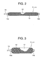
- Fig. 2 is a side view of each of the actuators 7 through 11 of Fig. 1
- Fig. 3 is a side view of each of the actuators 7 through 11 of Fig. 1 in a swollen state. While in Fig. 1 the first through fifth actuators 7 through 11 are shown simply as curves, each of the actuators 7 through 11 has a construction as shown in Figs. 2 and 3. Further, in Figs. 2 and 3, part of the mesh sleeve is cut away in order to show the internal structure.
- pneumatic actuators which are fluid pressure type actuators, are used.
- a supply/discharge pipe 15 Connected to one end in the longitudinal direction of an inner tube 12 as an expansion/contraction body is a supply/discharge pipe 15 for supplying and discharging air serving as the fluid to and from the inner tube 12.
- a bush (not shown) is inserted into the other longitudinal end portion of the inner tube 12 for hermetic sealing.
- the inner tube 12 is formed of an elastic material such as silicone rubber or butyl rubber.
- the outer periphery of the inner tube 12 is covered with a mesh sleeve 13, which is a net-like covering member.
- the mesh sleeve 13 is formed, for example, of filaments (wires) of high tensile fibers or the like such as nylon or polyester fiber that has no elasticity.
- the fibers are woven so as to cross the longitudinal direction of the mesh sleeve 13.
- the longitudinal end portions of the mesh sleeve 13 are fastened by fastening members 14a, 14b, whereby they are fixed to the end portions of the inner tube 12.
- the inner tube 12 expands when air is supplied into it. Since the filaments forming the mesh sleeve 13 have no elasticity, the expansion of the inner tube 12 is converted to a reduction in the total length of the actuator. That is, when supplied with air, the length of each of the actuators 7 through 11 is reduced while its diameter increases. Due to this reduction in length, the actuators 7 through 11 generates driving force (pulling force).
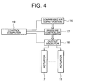
- Fig. 4 is a block diagram showing the construction of the drive control portion of the wearable joint driving device of Fig. 1.
- the actuators 7 through 11 are supplied with air from a compressed air supply portion 16 consisting, for example, of a small air compressor.
- the pressure of the air supplied from the compressed air supply portion 16 to the actuators 7 through 11 is adjusted by one or a plurality of pressure controllers 17. Further, the supply of air to the actuators 7 through 11 is effected selectively or in parallel by an output selector 18.
- the compressed air supply portion 16, the pressure controller 17, and the output selector 18 are controlled by a control computer 19.
- a control unit has the pressure controller 17 and the output selector 18.
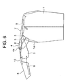
- the upper arm frame 2 is rotated from a first position (Fig. 1) to a second position (Fig. 5) relative to the torso frame 1 by the driving force of the first and second actuators 7, 8. Then, by driving the third actuator 9, with the upper arm frame 2 being at the second position (Fig. 5), the upper arm frame 2 is rotated together with the shoulder frame 4. As a result, the upper arm frame 2 is rotated to a third position (Fig. 6) where the angle it makes with the first position (Fig. 1) is larger than that when it is at the second position (Fig. 5).
- the torso frame 1, the upper arm frame 2, the shoulder frame 4, and the forearm frame 6 have a predetermined level of rigidity which, even if they are not on the human body, allows them to operate in the same manner as when they are on the human body, so that generation of wrinkles and looseness in the frames 1, 2, 4, 6 is prevented, making it possible to achieve an improvement in terms of driving force transmission efficiency and to achieve an increase in operating amount and driving force.
- the frames 1, 2, 4, 6 also function as armor-like frames like the outer skeleton of a crustacean, such as an insect.
- the combination and arrangement of the frames it is desirable to adopt, taking into account the actual arrangement of bones, joint portions, and muscles of the human, ones in which there is no local excessive load on the skin, bones, and joints in various limb portions, making the rotation centers of the joint portions as the same as or equivalent to those for the movements of the human body.
- the shoulder and the peripheral joint portion have ceased to be treated as a joint with only one rotation axis, making it possible to realize an operation equivalent to that of the human body, in which the rotation center undergoes transition according to the operation.
- a belt for fixing the torso frame 1 to the human body, so that absorption of the driving force of the actuators 7 through 11 by the movement of the torso frame 1 is prevented, making it possible to achieve a further improvement in driving force transmission efficiency. Further, the force from the actuators 7 through 11 is received by the torso frame 1, and not by the belt, so that no load from the belt is applied to the wearing person.
- shoulder frame 4 and the third actuator 9 are used in order to expand the rotation range for the upper arm frame 2, it is also possible to use a rotation support member and an auxiliary member actuator for expanding the rotation range for another frame member.
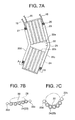
- Fig. 7a is a side view of a wearable joint driving device according to Embodiment 2 of the present invention
- Fig. 7b is a sectional view taken along the line A-A of Fig. 7a
- Fig. 7c is a sectional view showing a state in which air has been supplied to the frame tube of Fig. 7b
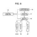
- Fig. 8 is a block diagram showing the construction of the operation control portion of the wearable joint driving device of Fig. 7a.
- the device shown is of the type which is put on a knee portion of the human body to cause the knee joint to make bending and stretching motions. Further, a thigh portion and a lower leg portion, to which this device is put on, are rotatably connected at the knee portion constituting the joint portion.
- a frame member 21 has a support member 22 on which the thigh portion and the lower leg portion are placed, and first and second frame tubes 23, 24 contained in the support member 22. Air is supplied to the first and second frame tubes 23, 24 through a supply/discharge tube 25. By supplying air to the frame tubes 23, 24, the frame member 21 attains a predetermined level of rigidity, and the frame member 21 is flexible with the air discharged therefrom.
- the support member 22 has a first accommodating portion 22a accommodating the first frame tubes 23, a second accommodating portion 22b accommodating the second frame tubes 24, a first actuator inserting portion 22c, and a second actuator inserting portion 22d. As shown in section in Fig. 7b, the first accommodating portion 22a and the second accommodating portion 22b are formed such that the top portions of the tubes arranged in parallel are connected to each other.
- a first actuator 26 is inserted into the first actuator inserting portion 22c. The end portions of the first actuator 26 are fixed to the support member 22.
- a second actuator 27 is inserted into the second actuator inserting portion 22d. The end portions of the second actuator 27 are fixed to the support member 22.
- the construction of the first and second actuators 26, 27 is the same as that shown in Figs. 2 and 3.
- the wearable joint driving device by supplying air to the first and second frame tubes 23, 24, the first and second accommodating portions 22a, 22b are formed into a concave configuration as shown in Fig. 7c, wrapping the thigh portion and the lower leg portion placed thereon. Then, by supplying and discharging air to and from the first and second actuators 26, 27, a pulling force is exerted on the frame member 21, allowing the knee joint to bend and stretch.
- the frame member 21 attains a predetermined level of rigidity (a level of rigidity allowing the same operation irrespective of whether it is on the human body or not), so that it is possible to achieve an improvement in terms of driving force transmission efficiency, making it possible to increase the operating amount and the driving force. Further, with air discharge therefrom, the frame member 21 is flexible, so that it is possible to achieve an improvement in terms of comfort during use. Further, when the device is not in use, its accommodation and transportation can be facilitated. Further, it is possible to achieve a reduction in the weight of the device as a whole, and an improvement in terms of comfort when the device on the human body.
- the support member 22 may form on the front side or the back side of the frame tubes 23, 24 a bag-like member 28 into which the arm or the leg is to be inserted.
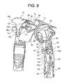
- Fig. 9 is a perspective view, as seen obliquely from the front right-hand side, of a wearable joint driving device according to Embodiment 3 of the present invention
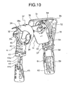
- Fig. 10 is a perspective view, as seen obliquely from the front left-hand side, of the wearable joint driving device of Fig. 9
- Fig. 11 is a perspective view, as seen obliquely from the rear left-hand side, of the wearable joint driving device of Fig. 9
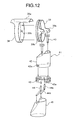
- Fig. 12 is an exploded perspective view showing the left-arm side frame construction of the wearable joint driving device of Fig. 9. While Figs. 9 through 11 only show an actuator for driving the left arm for the sake of simplicity, in reality, there is arranged, symmetrically therewith, an actuator for driving the right arm.
- a torso frame 31 as a first frame member is put on the torso.
- the torso frame 31 is provided with a head portion insertion hole 31a through which the head portion is to be passed.
- the torso frame 31 has a torso frame main body 32 supported by the shoulder, a chest frame 33 rotatably connected to the torso frame main body 32 through the intermediation of a plurality of hinges 34 and abutting the chest portion, and a protrusion 35 protruding upwardly from the back portion of the torso frame main body 32 and facing the neck or the back of the head.
- the torso frame 31 does not entirely cover the upper part of the body but sandwiches solely the chest portion and the upper part of the back between front and rear.
- the chest frame 33 is rotated relative to the torso frame main body 32 according to the figure of the wearing person.
- a shoulder frame 37 as a rotation support member is connected to each shoulder portion of the torso frame main body 32 through the intermediation of a joint portion 36.
- the shoulder frame 37 has a ring-like shoulder frame main body 38 connected to the joint portion 36, and a ring-like shoulder frame rotating portion 39 rotatably fit-engaged within the shoulder frame main body 38.
- the shoulder frame main body 38 is provided with an extension 38a with an arcuate sectional configuration extending outwards. Further, on the inner peripheral surface of the shoulder frame main body 38, there is provided a protrusion 38b (Fig. 12) guiding the rotation of the shoulder frame rotating portion 39.
- the shoulder frame rotating portion 39 is provided with a pair of upper arm frame connecting portions 39a. Further, in the outer peripheral surface of the shoulder frame rotating portion 39, there is provided a guide groove 39b (Fig. 12) into which the protrusion 38b is inserted. When the shoulder frame rotating portion 39 is rotated relative to the shoulder frame main body 38, the protrusion 38b makes a relative sliding movement within the guide groove 39b.
- a cylindrical upper arm frame 41 as a second frame member is connected to the shoulder frame rotating portion 39 through the intermediation of a pair of upper arm frame connecting belts 40.
- the upper end portions of the upper arm frame connecting belts 40 are fixed to the upper arm frame connecting portions 39a.
- the upper arm frame 41 has a cylindrical upper arm frame main body 42 connected to the upper arm frame connecting belts 40, and a ring-like upper arm frame rotating portion 43 rotatably fit-engaged with the outer peripheral portion of the upper arm frame main body 42.
- the upper arm frame rotating portion 43 On the outer peripheral surface of the upper arm frame main body 42, there are provided a pair of protrusions 42a (Fig. 12) guiding the rotation of the upper arm frame rotating portion 43.
- the upper arm frame rotating portion 43 is provided with a pair of guide slits 43a into which the protrusions 42a are inserted.
- the protrusions 42a make a relative sliding movement within the guide slits 43a.
- a cylindrical forearm frame 45 is connected to the upper arm frame rotating portion 43 through the intermediation of a pair of link members 44.
- Each link member 44 has a first link member 44a connected to the upper arm frame rotating portion 43, and a second link member 44b connected to the forearm frame 45.
- the first and second link members 44a, 44b are rotatably connected to each other.
- the torso frame 31, the shoulder frame 37, the upper arm frame 41, and the forearm frame 45 are formed of a metal, such as aluminum or aluminum alloy.
- a first actuator 51 as an auxiliary member actuator for rotating the shoulder frame 37 relative to the torso frame 31.
- the end portions of the first actuator 51 are respectively fixed to the protrusion 35 and the extension 38a.
- a second actuator 52 as an auxiliary member actuator for rotating the shoulder frame 37 relative to the torso frame 31.
- the end portions of the second actuator 52 are respectively fixed to the chest frame 33 and the extension 38a.
- a third actuator 53 (shown only in Fig. 11) as an auxiliary member actuator for rotating the shoulder frame 37 relative to the torso frame 31.
- the end portions of the third actuator 53 are respectively fixed to the torso frame main body 32 and the extension 38a.
- a fourth actuator 54 for rotating the upper arm frame 41 and the shoulder frame rotating portion 39 relative to the shoulder frame main body 38.
- the fourth actuator 54 is arranged so as to be wrapped around the outer peripheral surface of the shoulder frame main body 38. Further, the end portions of the fourth actuator 54 are respectively fixed to the shoulder frame main body 38 and the upper arm frame main body 42.
- a fifth actuator 55 for rotating the upper arm frame 41 and the shoulder frame rotating portion 39 relative to the shoulder frame main body 38.
- the fifth actuator 55 is arranged so as to be wrapped around the outer peripheral surface of the shoulder frame main body 38. Further, the end portions of the fifth actuator 55 are respectively fixed to the shoulder frame main body 38 and the upper arm frame main body 42.
- the driving forces generated by the fourth and fifth actuators 54, 55 are in opposite directions.
- a sixth actuator 56 as a second frame member actuator for rotating the upper arm frame 41 relative to the torso frame 31.
- the end portions of the sixth actuator 56 are respectively fixed to the protrusion 35 and the upper arm frame main body 42.
- seventh and eighth actuators 57, 58 for rotating the upper arm frame rotating portion 43 and the forearm frame 45 relative to the upper arm frame main body 42.
- the seventh and eighth actuators 57, 58 are arranged so as to be wrapped around the outer peripheral surface of the upper arm frame 41.
- the end portions of the seventh and eighth actuators 57, 58 are respectively fixed to the upper arm frame main body 42 and the upper arm frame rotating portion 43.
- the driving forces generated by the seventh and eighth actuators 57, 58 are in opposite directions.
- ninth through twelfth actuators 59 through 62 for rotating the forearm frame 45 relative to the upper arm frame 41.
- the end portions of the ninth through twelfth actuators 59 through 62 are respectively fixed to the first link member 44a and the forearm frame 45.
- a thirteenth actuator 63 (shown only in Fig. 11) for rotating the forearm frame 45 relative to the upper arm frame 41.
- Fig. 13 is a perspective view of the joint portion 36 of Fig. 9.
- a base 64 is fixed to the torso frame main body 32.
- the base 64 is provided with a shaft 65.
- the axis of the shaft 65 is parallel to the X-axis in the drawing.
- a rotation base 66 mounted on the base 64 is a rotation base 66 rotatable by 360 degrees around the shaft 65.
- a shoulder frame connecting member 68 is connected to the rotation base 66 through the intermediation of a hinge 67.
- the shoulder frame connecting member 68 is rotatable by 180 degrees with respect to the rotation base 66.
- the rotation axis of the shoulder frame connecting member 68 is parallel to the Y-axis in the drawing.
- the shoulder frame main body 38 is fixed to the shoulder frame connecting member 68.
- the basic construction of the first through thirteenth actuators 51 through 63 is the same as that shown in Figs. 2 and 3.
- the control system for the first through thirteenth actuators 51 through 63 is the same as that of Embodiment 1 (Fig. 4).
- the cover is also effective to use a cover covering the outer peripheral portion and the inner peripheral portion of the entire device in order to prevent clothes from being caught by the frames and to prevent the actuators from colliding with peripheral objects to suffer damage, when actually putting on the device.
- the cover can be formed, for example, of cloth.
- the upper arm frame 41 is rotated from a first position to a second position with respect to the torso frame 31 by the driving force of the sixth actuator 56.
- the upper arm frame 41 is rotated together with the shoulder frame 37. This causes the upper arm frame 41 to be rotated to a third position where the angle it makes with the first position is larger than that when it is at the second position.
- the shoulder frame 37 is rotated around the shaft 65 of the joint portion 36 so as to move the shoulder forwards and backwards.
- the shoulder frame rotating portion 39 and the upper arm frame 41 are rotated so as to swing the arm forwards and backwards.
- the upper arm frame rotating portion 43 and the forearm frame 45 are rotated so as to twist the forearm relative to the upper arm.
- air is selectively supplied to the ninth through thirteenth actuators 59 through 63, whereby the forearm frame 45 is rotated so as to bend and stretch the forearm relative to the upper arm.
- the torso frame 31 has the torso frame main body 32 supported by the shoulder portion of the torso, and the chest frame 33 rotatably connected to the torso frame main body 32 and abutting the chest portion of the torso, so that it is possible to facilitate the wearing of the device as a whole regardless of the figure of the wearing person, making it possible to substantially reduce the requisite time for putting on and taking off the device.
- the torso frame 31 is provided with the protrusion 35 protruding from the back portion of the torso frame main body 32, and the first and sixth actuators 51, 56 are connected to the protrusion 35, so that the arrangement of the actuators 51, 56 is facilitated, and it is possible to effectively exert the driving force of the actuators 51, 56.
- the joint portion 36 has the rotation base 66 rotatable around the shaft 65, and the shoulder frame connecting member 68 rotatably connected to the rotation base 66 through the intermediation of the hinge 67, so that it is possible to achieve an improvement in terms of degree of freedom for the operation of the shoulder frame 37, making it possible to realize various movements.
- the shoulder frame 37 is provided with the extension 38a extending outwards, and the first and second actuators 51, 52 are provided between the torso frame 31 and the extension 38a, so that the arrangement of the actuators 51, 52 is facilitated, and the driving force of the actuators 51, 52 can be effectively exerted.
- the shoulder frame 37 has the shoulder frame main body 38, and the shoulder frame rotating portion 39 rotatably fit-engaged with the shoulder frame main portion 38, so that the upper arm frame can be rotated so as to move the upper arm forwards and backwards with a simple structure.
- the upper arm frame 41 has the upper arm frame main body 42, and the upper arm frame rotating portion 43 rotatably fit-engaged with the upper arm frame main body 42, so that it is possible to rotate the forearm frame so as to twist the forearm relative to the upper arm with a simple structure.
- the shoulder frame 37, the upper arm frame 41, and the forearm frame 45 described above can be operated singly or in combination by driving selectively or in parallel predetermined ones of the actuators 51 through 63.
- the forearm frame 45 is connected to the upper arm frame 41 through the link bodies with the first and second link members 44a, 44b, so that it is possible to reduce the sizes of the upper arm frame 41 and the forearm frame 45, thereby achieving a reduction in the weight as a whole.
- Fig. 14 is a perspective view of the torso frame of a wearable joint driving device according to Embodiment 4 of the present invention.
- a torso frame 71 has a front surface portion 72 covering the front surface of the torso, and a back surface portion 73 covering the back surface of the torso.
- the front surface portion 72 and the back surface portion 73 are rotatably connected to each other at connecting portions 71a, 71b situated on the shoulder portions through the intermediation of hinges (not shown).
- the torso frame 71 is provided with sleeve openings 71c, 71d through which the arms are to be passed, and a neck opening 71e through which the neck is to be passed.
- shoulder frame mounting portions 74, 75 Fixed to the shoulder portions of the torso frame 71 are shoulder frame mounting portions 74, 75 for the mounting of the shoulder frame 37 as shown, for example, in Embodiment 3.
- the front surface portion 72 and the back surface portion 73 are first opened, and the arms are passed through the sleeve openings 71c, 71d, thus the torso frame 71 is attached to the torso. Thereafter, the shoulder frame 37 is mounted to the shoulder frame mounting portions 72, 73.
- the upper arm frame 41 and the forearm frame 45 as shown in Embodiment 3 are previously connected to the shoulder frame 37 to be assembled as an arm attachment unit. Further, the actuators 51 through 63 are also previously mounted to the arm attachment unit.
- the mounting of the shoulder frame 37 to the shoulder frame mounting portions 72, 73 is effected after the arms have been passed through the arm attachment unit. Thereafter, the actuators 51, 52, 56 are connected to the torso frame 71.
- the wearable joint driving device of the present invention can assist the person in his or her action. Further, when worn by a person in normal health, it generates a force exceeding the muscular power of the wearing person to assist him or her in operation. As a result, it is possible to mitigate the physical burden on a person performing nursing/assistance, for example. That is, it is possible even for an aged person or a woman to perform a heavy work, such as taking up somebody in his or her arms. Further, regardless of whether a person is in normal health or physically handicapped, it is possible to assist him or her in performing physical work, maintain his or her posture, assist posture maintenance, or amplify his or her force.
- the wearable joint driving device of the present invention can be used as a robot drive source.
- the device can be used in an X-ray inspection with an external force applied. Further, it can also be used in an MRI inspection and a CT inspection.
Abstract
Description
Claims (14)
- A wearable joint driving device worn by a driven body having a plurality of wearingmembers and at least one joint portion rotatably connecting the wearing members to drive the joint portion, the wearable joint driving device comprising:a plurality of frame members of a predetermined rigidity to be attached to the wearing members so as to be in contact with outer surfaces of the wearing members;at least one fluid pressure type actuator having an expansion/contraction member undergoing expansion/contraction through supply/discharge of a fluid and a net-like covering member covering an outer periphery of the expansion/contraction member, and mounted between the frame members, the expansion/contraction member being reduced in length through expansion to thereby generate a driving force; anda control unit for controlling supply and discharge of the fluid to and from the fluid pressure type actuator.
- A wearable joint driving device according to Claim 1, wherein the frame members attain the predetermined rigidity through supply of the fluid into their interior, and are flexible with the fluid discharged therefrom.
- A wearable joint driving device according to Claim 1, wherein a plurality of the fluid pressure type actuators are provided, the fluid being supplied or discharged selectively or in parallel to or from the fluid pressure type actuators by the control unit.
- A wearable joint driving device according to Claim 1, wherein the driven body has a torso and an upper arm constituting the wearing members, and a shoulder joint portion constituting the joint portion, and
wherein the frame members include a torso frame attached to the torso, a shoulder frame rotatably connected to the torso frame, and an upper arm frame rotatably connected to the shoulder frame and attached to the upper arm. - A wearable joint driving device according to Claim 4, wherein the torso frame has a torso frame main body supported by a shoulder portion of the torso, and a chest frame rotatably connected to the torso frame main body and in contact with a chest portion of the torso.
- A wearable joint driving device according to Claim 4, wherein the torso frame has a torso frame main body supported by a shoulder portion of the torso, and a protrusion which protrudes from a back portion of the torso frame main body and to which the fluid pressure type actuator is connected.
- Awearable joint driving device according to Claim 4, wherein the torso frame and the shoulder frame are connected to each other through the intermediation of a joint portion, and
wherein the joint portion has a base fixed to the torso frame, a shaft provided on the base, a rotation base mounted on the base and rotatable around the shaft, and a shoulder frame connecting member rotatably connected to the rotation base through the intermediation of a hinge and fixed to the shoulder frame. - Awearable joint driving device according to Claim 4, wherein the shoulder frame is provided with an extension extending outwardly, and wherein the fluid pressure type actuator is provided between the torso frame and the extension.
- Awearable joint driving device according to Claim 4, wherein the shoulder frame has a ring-like shoulder frame main body connected to the torso frame, and a ring-like shoulder frame rotating portion rotatably fit-engaged with the shoulder frame main body and to which the upper arm frame is connected.
- Awearable joint driving device according to Claim 1, wherein the driven body has an upper arm and a forearm constituting the wearing members, and an elbow joint portion constituting the joint portion, and
wherein the frame members include an upper arm frame attached to the upper frame, and a forearm frame rotatably connected to the upper arm frame and attached to the forearm, the fluid pressure type actuator being connected between adjacent frames or between frames spaced apart from each other. - Awearable joint driving device according to Claim 10, wherein the upper arm frame has a cylindrical upper arm frame main body, and a ring-like upper arm frame rotating portion which is rotatably fit-engaged with the upper arm frame main body and to which the forearm frame is connected.
- Awearable joint driving device according to Claim 10, wherein the forearm frame is connected to an upper arm frame through the intermediation of a link body,
wherein the link body has a first link member connected to the upper arm frame and a second link member connected to the forearm frame, and
wherein the first and second link members are rotatably connected to each other. - Awearable joint driving device worn by a driven body having first and second wearing members and a joint portion rotatably connecting the first and second wearing members to drive the joint portion, the wearable joint driving device comprising:wherein the second frame member actuator and the support member actuator are fluid pressure type actuators respectively having an expansion/contraction member undergoing expansion/contraction through supply/discharge of a fluid and a net-like covering member covering an outer periphery of the expansion/contraction member, the expansion/contraction member being reduced in length through expansion to generate a driving force,a first frame member to be attached to the first wearing member;a second frame member to be attached to the second wearing member;a rotation support member rotatably connected to the first frame member;a second frame member actuator provided between at least one of the first frame member and the rotation support member and the second frame member and adapted to rotate the second frame member with respect to the first frame member; anda support member actuator provided between the first frame member and the rotation support member and adapted to rotate the rotation support member with respect to the first frame member,
wherein the second frame member is rotated from a first position to a second position by the driving force of the second frame member actuator, and
wherein, by driving the support member actuator with the second frame member being at the second position, the second frame member is rotated together with the rotation support member, whereby the second frame member is rotated to a third position where the angle the second frame member makes with the first position is larger than that when the second frame member is at the second position. - A wearable joint driving device according to Claim 13, wherein the first wearing member is a torso, the second wearing member is an upper arm, and the joint portion is a shoulder joint portion,
wherein the first frame member is a torso frame to be attached to the torso, the second frame member is an upper arm frame to be attached to the upper arm, and the rotation support member is a shoulder frame rotatably connected to the torso frame.
Applications Claiming Priority (3)
| Application Number | Priority Date | Filing Date | Title |
|---|---|---|---|
| JP2003091280 | 2003-03-28 | ||
| JP2003091280 | 2003-03-28 | ||
| PCT/JP2004/003635 WO2004087033A1 (en) | 2003-03-28 | 2004-03-18 | Wear-type joint drive device |
Publications (2)
| Publication Number | Publication Date |
|---|---|
| EP1609451A1 true EP1609451A1 (en) | 2005-12-28 |
| EP1609451A4 EP1609451A4 (en) | 2010-02-10 |
Family
ID=33127277
Family Applications (1)
| Application Number | Title | Priority Date | Filing Date |
|---|---|---|---|
| EP04721649A Withdrawn EP1609451A4 (en) | 2003-03-28 | 2004-03-18 | Wear-type joint drive device |
Country Status (5)
| Country | Link |
|---|---|
| US (1) | US7413554B2 (en) |
| EP (1) | EP1609451A4 (en) |
| JP (1) | JP4542036B2 (en) |
| CN (1) | CN1753653A (en) |
| WO (1) | WO2004087033A1 (en) |
Cited By (9)
| Publication number | Priority date | Publication date | Assignee | Title |
|---|---|---|---|---|
| WO2009017442A1 (en) * | 2007-07-27 | 2009-02-05 | Otto Bock Scandinavia Ab | Shoulder orthosis |
| GB2455427B (en) * | 2005-10-11 | 2009-12-02 | Panasonic Corp | Motion Assistance Apparatus |
| DE102008059505A1 (en) * | 2008-11-28 | 2010-06-02 | Dürr Systems GmbH | Protective cover for dirt protection of a robot |
| US8360997B2 (en) | 2006-02-24 | 2013-01-29 | Ferrobotics Compliant Robot Technology Gmbh | Robot arm |
| DE102013223603A1 (en) | 2013-11-19 | 2015-05-21 | Ferrobotics Compliant Robot Technology Gmbh | robot arm |
| NL2011907C2 (en) * | 2013-12-06 | 2015-06-09 | Univ Delft Tech | Upper limb exoskeleton. |
| EP3346142A4 (en) * | 2015-08-31 | 2019-05-15 | Daiya Holdings Co.,Ltd. | Actuator and body assistance device |
| SE541434C2 (en) * | 2016-10-05 | 2019-10-01 | Bioservo Tech Aktiebolag | Arm lifting support device |
| WO2020038850A1 (en) * | 2018-08-22 | 2020-02-27 | Exoiq Gmbh | System and method for the reduction of forces acting on an arm of a human |
Families Citing this family (94)
| Publication number | Priority date | Publication date | Assignee | Title |
|---|---|---|---|---|
| JP4564788B2 (en) * | 2004-06-16 | 2010-10-20 | 俊郎 則次 | Wearable power assist device |
| JP2006340852A (en) * | 2005-06-08 | 2006-12-21 | Natl Rehabilitation Center For The Disabled | Wear type joint drive device |
| JP4645392B2 (en) * | 2005-09-27 | 2011-03-09 | カシオ計算機株式会社 | Strength assist device |
| JPWO2007058107A1 (en) * | 2005-11-15 | 2009-04-30 | 日本シグマックス株式会社 | Fluid pressure type actuator and exercise device using the same |
| JP4407632B2 (en) * | 2005-12-26 | 2010-02-03 | パナソニック株式会社 | Strength assist device |
| JP4735461B2 (en) * | 2006-07-26 | 2011-07-27 | パナソニック電工株式会社 | Knee pain relief device |
| WO2008045522A2 (en) * | 2006-10-12 | 2008-04-17 | The Board Of Trustees Of The University Of Illinois | Motion therapy system |
| CN1961848B (en) * | 2006-11-24 | 2010-09-22 | 浙江大学 | Flexible exoskeleton elbow joint based on pneumatic muscles |
| JP5148898B2 (en) * | 2007-02-27 | 2013-02-20 | 茂樹 遠山 | Wearable robot arm support |
| WO2009014644A1 (en) * | 2007-07-20 | 2009-01-29 | Ossur Hf | Prosthetic or orthopedic device having feedback |
| US20100280423A1 (en) * | 2007-12-28 | 2010-11-04 | Panasonic Corporation | Muscle force assisting device (as amended) |
| US20100280424A1 (en) * | 2008-03-27 | 2010-11-04 | Panasonic Corporation | Muscle force assisting device |
| JP5194213B2 (en) * | 2008-05-12 | 2013-05-08 | 学校法人 芝浦工業大学 | Scapula clavicle mechanism |
| JP5169469B2 (en) * | 2008-05-15 | 2013-03-27 | 学校法人東京理科大学 | Upper arm holding device and upper arm assist device |
| FR2932081B1 (en) * | 2008-06-10 | 2010-05-14 | Commissariat Energie Atomique | SHOULDER MECHANISM FOR ORTHESIS. |
| US8409117B2 (en) * | 2008-09-15 | 2013-04-02 | The Hong Kong Polytechnic University | Wearable device to assist with the movement of limbs |
| JP5472680B2 (en) * | 2009-04-09 | 2014-04-16 | 国立大学法人 筑波大学 | Wearable motion assist device |
| KR101157342B1 (en) | 2010-04-16 | 2012-06-15 | 경희대학교 산학협력단 | A apparatus for rehabilitating whole body using wires |
| JP5344501B2 (en) * | 2011-12-27 | 2013-11-20 | 国立大学法人 筑波大学 | Wearable motion assist device and control method thereof |
| JP2013146328A (en) * | 2012-01-18 | 2013-08-01 | Seiko Epson Corp | Device for supporting operation |
| US10028878B1 (en) * | 2012-11-28 | 2018-07-24 | Vecna Technologies, Inc. | Body worn apparatus |
| US9345609B2 (en) | 2013-01-11 | 2016-05-24 | Elwha Llc | Position sensing active torso support |
| US10314733B2 (en) | 2012-12-20 | 2019-06-11 | Elwha Llc | Sensor-based control of active wearable system |
| JP5524321B2 (en) * | 2012-12-27 | 2014-06-18 | パナソニックヘルスケア株式会社 | Muscle assist device and method of operating the same |
| US10420666B2 (en) | 2013-04-08 | 2019-09-24 | Elwha Llc | Apparatus, system, and method for controlling movement of an orthopedic joint prosthesis in a mammalian subject |
| US9439797B2 (en) | 2013-04-08 | 2016-09-13 | Elwha Llc | Apparatus, system, and method for controlling movement of an orthopedic joint prosthesis in a mammalian subject |
| WO2015066143A1 (en) * | 2013-10-29 | 2015-05-07 | President And Fellows Of Harvard College | Multi-segment reinforced actuators and applications |
| KR101510019B1 (en) * | 2013-12-18 | 2015-04-07 | 현대자동차주식회사 | Wire-driven robot |
| US10611020B2 (en) | 2013-12-19 | 2020-04-07 | Roam Robotics Inc. | Pneumatic exomuscle system and method |
| US10012229B2 (en) * | 2013-12-19 | 2018-07-03 | Other Lab Llc | Diaphragm compressor system and method |
| CN103707284B (en) * | 2013-12-29 | 2016-01-20 | 哈尔滨理工大学 | Wearable upper limb power assistant arm and boosting method thereof |
| WO2015106278A2 (en) * | 2014-01-13 | 2015-07-16 | Massachusetts Institute Of Technology | Wearable robot assisting manual tasks |
| US9915545B2 (en) | 2014-01-14 | 2018-03-13 | Toyota Motor Engineering & Manufacturing North America, Inc. | Smart necklace with stereo vision and onboard processing |
| US10248856B2 (en) | 2014-01-14 | 2019-04-02 | Toyota Motor Engineering & Manufacturing North America, Inc. | Smart necklace with stereo vision and onboard processing |
| US10024679B2 (en) | 2014-01-14 | 2018-07-17 | Toyota Motor Engineering & Manufacturing North America, Inc. | Smart necklace with stereo vision and onboard processing |
| US9578307B2 (en) | 2014-01-14 | 2017-02-21 | Toyota Motor Engineering & Manufacturing North America, Inc. | Smart necklace with stereo vision and onboard processing |
| US9629774B2 (en) | 2014-01-14 | 2017-04-25 | Toyota Motor Engineering & Manufacturing North America, Inc. | Smart necklace with stereo vision and onboard processing |
| US10360907B2 (en) | 2014-01-14 | 2019-07-23 | Toyota Motor Engineering & Manufacturing North America, Inc. | Smart necklace with stereo vision and onboard processing |
| WO2015191122A1 (en) * | 2014-06-13 | 2015-12-17 | Worcester Polytechnic Institute | Actuators and methods of use |
| US10024667B2 (en) | 2014-08-01 | 2018-07-17 | Toyota Motor Engineering & Manufacturing North America, Inc. | Wearable earpiece for providing social and environmental awareness |
| US10024678B2 (en) | 2014-09-17 | 2018-07-17 | Toyota Motor Engineering & Manufacturing North America, Inc. | Wearable clip for providing social and environmental awareness |
| US9922236B2 (en) | 2014-09-17 | 2018-03-20 | Toyota Motor Engineering & Manufacturing North America, Inc. | Wearable eyeglasses for providing social and environmental awareness |
| USD768024S1 (en) | 2014-09-22 | 2016-10-04 | Toyota Motor Engineering & Manufacturing North America, Inc. | Necklace with a built in guidance device |
| CN104306088B (en) * | 2014-10-30 | 2016-07-06 | 上海交通大学 | There is the above elbow prosthesis module of active shoulder joint |
| US9576460B2 (en) | 2015-01-21 | 2017-02-21 | Toyota Motor Engineering & Manufacturing North America, Inc. | Wearable smart device for hazard detection and warning based on image and audio data |
| JP6489422B2 (en) * | 2015-01-28 | 2019-03-27 | パナソニックIpマネジメント株式会社 | Assist wear, assist wear operating method, and control program |
| DE102015101329A1 (en) * | 2015-01-29 | 2016-08-04 | Airbus Operations Gmbh | Support device for stabilizing a body part of a person |
| US10490102B2 (en) | 2015-02-10 | 2019-11-26 | Toyota Motor Engineering & Manufacturing North America, Inc. | System and method for braille assistance |
| WO2016129716A1 (en) * | 2015-02-11 | 2016-08-18 | 한국기술교육대학교 산학협력단 | Upper-limb exercising device of a type worn on the body |
| KR101630570B1 (en) | 2015-02-27 | 2016-06-15 | 서울대학교산학협력단 | Assisting Device for Muscle Strength |
| KR101677920B1 (en) * | 2015-02-27 | 2016-11-21 | 한국기술교육대학교기술지주 주식회사 | Wearable Type Exercise Equipment for Upper Limb |
| US9586318B2 (en) | 2015-02-27 | 2017-03-07 | Toyota Motor Engineering & Manufacturing North America, Inc. | Modular robot with smart device |
| US9811752B2 (en) | 2015-03-10 | 2017-11-07 | Toyota Motor Engineering & Manufacturing North America, Inc. | Wearable smart device and method for redundant object identification |
| US9677901B2 (en) | 2015-03-10 | 2017-06-13 | Toyota Motor Engineering & Manufacturing North America, Inc. | System and method for providing navigation instructions at optimal times |
| US9972216B2 (en) | 2015-03-20 | 2018-05-15 | Toyota Motor Engineering & Manufacturing North America, Inc. | System and method for storing and playback of information for blind users |
| WO2016160624A1 (en) | 2015-03-27 | 2016-10-06 | Other Lab Llc | Lower-leg exoskeleton system and method |
| US10028855B2 (en) | 2015-05-14 | 2018-07-24 | Worcester Polytechnic Institute | Variable stiffness devices and methods of use |
| US9898039B2 (en) | 2015-08-03 | 2018-02-20 | Toyota Motor Engineering & Manufacturing North America, Inc. | Modular smart necklace |
| JP6782947B2 (en) * | 2015-09-10 | 2020-11-11 | タカノ株式会社 | Surgical aids |
| US10569413B2 (en) | 2015-12-22 | 2020-02-25 | Ekso Bionics, Inc. | Exoskeleton and method of providing an assistive torque to an arm of a wearer |
| US10058994B2 (en) | 2015-12-22 | 2018-08-28 | Ekso Bionics, Inc. | Exoskeleton and method of providing an assistive torque to an arm of a wearer |
| US10024680B2 (en) | 2016-03-11 | 2018-07-17 | Toyota Motor Engineering & Manufacturing North America, Inc. | Step based guidance system |
| TWI584801B (en) * | 2016-04-15 | 2017-06-01 | 龍華科技大學 | Exoskeleton apparatus of pneumatic muscle with functions of upper limb power assist and rehabilitation training |
| US9958275B2 (en) | 2016-05-31 | 2018-05-01 | Toyota Motor Engineering & Manufacturing North America, Inc. | System and method for wearable smart device communications |
| US10561519B2 (en) | 2016-07-20 | 2020-02-18 | Toyota Motor Engineering & Manufacturing North America, Inc. | Wearable computing device having a curved back to reduce pressure on vertebrae |
| KR101814676B1 (en) * | 2016-07-25 | 2018-01-04 | 이동찬 | Wearable soft exoskeleton apparatus |
| US10432851B2 (en) | 2016-10-28 | 2019-10-01 | Toyota Motor Engineering & Manufacturing North America, Inc. | Wearable computing device for detecting photography |
| US10012505B2 (en) | 2016-11-11 | 2018-07-03 | Toyota Motor Engineering & Manufacturing North America, Inc. | Wearable system for providing walking directions |
| US10521669B2 (en) | 2016-11-14 | 2019-12-31 | Toyota Motor Engineering & Manufacturing North America, Inc. | System and method for providing guidance or feedback to a user |
| US10172760B2 (en) | 2017-01-19 | 2019-01-08 | Jennifer Hendrix | Responsive route guidance and identification system |
| CA3051105A1 (en) | 2017-02-03 | 2018-08-09 | Roam Robotics Inc. | System and method for user intent recognition |
| KR101917603B1 (en) * | 2017-02-28 | 2018-11-13 | 주식회사 에프알티 | Soft exoskeleton suit assisting muscular strength using metamaterial |
| JP6957600B2 (en) * | 2017-03-14 | 2021-11-02 | 株式会社Fuji | Caregiving device |
| WO2018191710A1 (en) | 2017-04-13 | 2018-10-18 | Other Lab, Llc | Leg exoskeleton system and method |
| US11026859B1 (en) * | 2017-04-20 | 2021-06-08 | United States Of America As Represented By The Administrator Of The National Aeronautics And Space Administration | Wearable robotic upper body garment |
| US10918559B2 (en) | 2017-04-25 | 2021-02-16 | Ossur Iceland Ehf | Interface system in an exoskeleton |
| WO2018218129A1 (en) * | 2017-05-25 | 2018-11-29 | Vanderbilt University | Upper extremity assistance device |
| JP2020522651A (en) * | 2017-05-31 | 2020-07-30 | プレジデント アンド フェローズ オブ ハーバード カレッジ | Textile actuator |
| WO2019031958A1 (en) * | 2017-08-10 | 2019-02-14 | Centro De Enseñanza Técnica Industrial | Apparatus for arm and shoulder muscle rehabilitation |
| IL282165B2 (en) | 2017-08-29 | 2024-01-01 | Roam Robotics Inc | Exoskeleton fit evaluation system and method |
| WO2019046488A1 (en) | 2017-08-29 | 2019-03-07 | Roam Robotics Inc. | Semi-supervised intent recognition system and method |
| TWI667049B (en) | 2017-09-25 | 2019-08-01 | 林宗正 | Sensor module capable of reducing noise |
| EP3687743B1 (en) | 2017-09-28 | 2023-10-25 | Ossur Iceland EHF | Body interface |
| CN107648012B (en) * | 2017-11-03 | 2023-12-01 | 中国科学院合肥物质科学研究院 | Flexible joint of wearable exoskeleton robot |
| CN110314065A (en) * | 2018-03-29 | 2019-10-11 | 京东方科技集团股份有限公司 | Exoskeleton rehabilitation power assisting device |
| USD876654S1 (en) | 2018-04-24 | 2020-02-25 | Ossur Iceland Ehf | Posterior strut |
| CN108498287A (en) * | 2018-04-25 | 2018-09-07 | 京东方科技集团股份有限公司 | Device for healing and training and rehabilitation training system |
| DE102018119755A1 (en) * | 2018-08-14 | 2020-02-20 | Ottobock Se & Co. Kgaa | Device for supporting at least one arm of a user |
| WO2020117963A1 (en) * | 2018-12-05 | 2020-06-11 | President And Fellows Of Harvard College | Textile actuator and harness system |
| CN109318217A (en) * | 2018-12-20 | 2019-02-12 | 赤源动力(大连)科技有限责任公司 | The wearable shoulder assistance exoskeleton of comfort can be improved |
| JP2020130629A (en) * | 2019-02-20 | 2020-08-31 | 宗正 林 | Sensor module with reduced noise |
| US11931307B2 (en) | 2019-12-13 | 2024-03-19 | Roam Robotics Inc. | Skiing exoskeleton control method and system |
| US20210259904A1 (en) | 2020-02-25 | 2021-08-26 | Roam Robotics Inc. | Fluidic actuator systems and methods for mobile robots |
| PL242832B1 (en) * | 2020-09-22 | 2023-05-02 | Icarion Spolka Z Ograniczona Odpowiedzialnoscia Spolka Komandytowa | Exoskeleton, especially a semi-passive one |
Citations (3)
| Publication number | Priority date | Publication date | Assignee | Title |
|---|---|---|---|---|
| DE3918955A1 (en) * | 1989-06-09 | 1989-12-21 | Ringer Michael | Technical simulation of the biological muscle principle as a technical muscle. Robot resembling an animal or a human being and having technical muscles. Parts of this robot as prostheses. Further applications of the muscle: as lifting and tensioning device, as muscle motor, for positioning of an object by several muscles, as adjustment means for the range of spring |
| JPH07204233A (en) * | 1994-01-19 | 1995-08-08 | Kazuhiro Kawada | Body assisting device |
| WO1995032842A2 (en) * | 1994-05-19 | 1995-12-07 | Exos, Inc. | Sensory feedback exoskeleton armmaster |
Family Cites Families (9)
| Publication number | Priority date | Publication date | Assignee | Title |
|---|---|---|---|---|
| US4531516A (en) * | 1983-02-07 | 1985-07-30 | David Clark Company Incorporated | Transparent pressure garment |
| JPH0588523U (en) * | 1991-06-28 | 1993-12-03 | 株式会社飯倉総合研究所 | Lower arm strength harness |
| US5257956A (en) * | 1992-04-14 | 1993-11-02 | Ewen Carol J | Post-mastectomy garment |
| US5391141A (en) * | 1992-11-10 | 1995-02-21 | Hamilton; Josef N. | Adjustable size and variable pressure regulated medical binder used by a patient after her or his body surgery |
| US5423333A (en) * | 1994-02-23 | 1995-06-13 | Orthopedic Systems, Inc. | Apparatus for shoulder immobilization |
| JP3174807B2 (en) * | 1996-04-05 | 2001-06-11 | 株式会社エム・イー・システム | Joint continuous passive exercise training device |
| JP4410920B2 (en) | 2000-09-22 | 2010-02-10 | 日本ロボティクス株式会社 | Pneumatic robot and pneumatic joint drive device |
| JP2002306282A (en) | 2001-04-17 | 2002-10-22 | Nippon Robotics Kk | Wearing type posture adjustor |
| JP2003301807A (en) | 2002-02-07 | 2003-10-24 | Nippon Robotics Kk | Fluid pressure actuator |
-
2004
- 2004-03-18 US US10/543,403 patent/US7413554B2/en not_active Expired - Fee Related
- 2004-03-18 EP EP04721649A patent/EP1609451A4/en not_active Withdrawn
- 2004-03-18 WO PCT/JP2004/003635 patent/WO2004087033A1/en active Application Filing
- 2004-03-18 JP JP2005504160A patent/JP4542036B2/en not_active Expired - Fee Related
- 2004-03-18 CN CN200480005340.8A patent/CN1753653A/en active Pending
Patent Citations (3)
| Publication number | Priority date | Publication date | Assignee | Title |
|---|---|---|---|---|
| DE3918955A1 (en) * | 1989-06-09 | 1989-12-21 | Ringer Michael | Technical simulation of the biological muscle principle as a technical muscle. Robot resembling an animal or a human being and having technical muscles. Parts of this robot as prostheses. Further applications of the muscle: as lifting and tensioning device, as muscle motor, for positioning of an object by several muscles, as adjustment means for the range of spring |
| JPH07204233A (en) * | 1994-01-19 | 1995-08-08 | Kazuhiro Kawada | Body assisting device |
| WO1995032842A2 (en) * | 1994-05-19 | 1995-12-07 | Exos, Inc. | Sensory feedback exoskeleton armmaster |
Non-Patent Citations (1)
| Title |
|---|
| See also references of WO2004087033A1 * |
Cited By (12)
| Publication number | Priority date | Publication date | Assignee | Title |
|---|---|---|---|---|
| GB2455427B (en) * | 2005-10-11 | 2009-12-02 | Panasonic Corp | Motion Assistance Apparatus |
| US8360997B2 (en) | 2006-02-24 | 2013-01-29 | Ferrobotics Compliant Robot Technology Gmbh | Robot arm |
| WO2009017442A1 (en) * | 2007-07-27 | 2009-02-05 | Otto Bock Scandinavia Ab | Shoulder orthosis |
| US10485692B2 (en) | 2007-07-27 | 2019-11-26 | Ottobock Se & Co. Kgaa | Shoulder orthosis |
| DE102008059505A1 (en) * | 2008-11-28 | 2010-06-02 | Dürr Systems GmbH | Protective cover for dirt protection of a robot |
| DE102013223603A1 (en) | 2013-11-19 | 2015-05-21 | Ferrobotics Compliant Robot Technology Gmbh | robot arm |
| WO2015074089A1 (en) | 2013-11-19 | 2015-05-28 | Ferrobotics Compliant Robot Technology Gmbh | Robot arm |
| NL2011907C2 (en) * | 2013-12-06 | 2015-06-09 | Univ Delft Tech | Upper limb exoskeleton. |
| WO2015084177A1 (en) * | 2013-12-06 | 2015-06-11 | Technische Universiteit Delft | Upper limb exoskeleton |
| EP3346142A4 (en) * | 2015-08-31 | 2019-05-15 | Daiya Holdings Co.,Ltd. | Actuator and body assistance device |
| SE541434C2 (en) * | 2016-10-05 | 2019-10-01 | Bioservo Tech Aktiebolag | Arm lifting support device |
| WO2020038850A1 (en) * | 2018-08-22 | 2020-02-27 | Exoiq Gmbh | System and method for the reduction of forces acting on an arm of a human |
Also Published As
| Publication number | Publication date |
|---|---|
| JP4542036B2 (en) | 2010-09-08 |
| EP1609451A4 (en) | 2010-02-10 |
| US20060161220A1 (en) | 2006-07-20 |
| US7413554B2 (en) | 2008-08-19 |
| CN1753653A (en) | 2006-03-29 |
| WO2004087033A1 (en) | 2004-10-14 |
| JPWO2004087033A1 (en) | 2006-06-29 |
Similar Documents
| Publication | Publication Date | Title |
|---|---|---|
| US7413554B2 (en) | Wearable joint driving device | |
| JP4736946B2 (en) | Walking aid | |
| KR102241853B1 (en) | Joint assembly and walking aid robot having the same | |
| KR102158131B1 (en) | Walking assist apparatus | |
| JP4573798B2 (en) | Lumbar support device | |
| KR102614776B1 (en) | A supporting module and a motion assist apparatus comprising thereof | |
| JP6825872B2 (en) | Power transmission module and exercise assist device including it | |
| JP7468532B2 (en) | Lumbar Assist Device | |
| CA2867742C (en) | Supportive belt assembly for lower extremity orthotic devices | |
| CN109925166B (en) | Exoskeleton rehabilitation system and exoskeleton rehabilitation method | |
| EP3257493A1 (en) | Upper-limb exercising device of a type worn on the body | |
| US20090048549A1 (en) | Orthopedic arm and shoulder brace | |
| JP2006340852A (en) | Wear type joint drive device | |
| KR102402876B1 (en) | Wearable apparatus for assisting muscle strength of wearer | |
| US8968223B2 (en) | Motion assist device | |
| JP2021501645A (en) | Hand exoskeleton device | |
| KR20180136940A (en) | Muscle strength assisting device | |
| JP5946203B1 (en) | Knee support orthosis | |
| KR20190002433A (en) | Muscle strength assisting device | |
| CN111568704A (en) | Lower limb rehabilitation exoskeleton based on rope transmission | |
| KR102449950B1 (en) | Wearable apparatus for assisting posture and muscle strength of wearer | |
| WO2020139115A1 (en) | Human postural support method and system for the implementation thereof | |
| CN110974627A (en) | Knee joint traction rehabilitation robot | |
| JP6970816B2 (en) | Walking aid | |
| PL242832B1 (en) | Exoskeleton, especially a semi-passive one |
Legal Events
| Date | Code | Title | Description |
|---|---|---|---|
| PUAI | Public reference made under article 153(3) epc to a published international application that has entered the european phase |
Free format text: ORIGINAL CODE: 0009012 |
|
| 17P | Request for examination filed |
Effective date: 20051024 |
|
| AK | Designated contracting states |
Kind code of ref document: A1 Designated state(s): AT BE BG CH CY CZ DE DK EE ES FI FR GB GR HU IE IT LI LU MC NL PL PT RO SE SI SK TR |
|
| AX | Request for extension of the european patent |
Extension state: AL LT LV MK |
|
| DAX | Request for extension of the european patent (deleted) | ||
| RBV | Designated contracting states (corrected) |
Designated state(s): DE FR GB IT NL |
|
| RIN1 | Information on inventor provided before grant (corrected) |
Inventor name: UCHIMURA, AKITAKA Inventor name: MUROMACHI, MASAAKI Inventor name: MATSUSHITA, TAISUKE Inventor name: KONAMI, MAKOTO Inventor name: HIRAMATSU, KAZUAKI Inventor name: SATO, YUTAKA Inventor name: KOBAYASHI, HIROSHI |
|
| RAP1 | Party data changed (applicant data changed or rights of an application transferred) |
Owner name: TOKYO UNIVERSITY OF SCIENCE Owner name: HITACHI MEDICAL CORPORATION |
|
| RAP1 | Party data changed (applicant data changed or rights of an application transferred) |
Owner name: TOKYO UNIVERSITY OF SCIENCE |
|
| A4 | Supplementary search report drawn up and despatched |
Effective date: 20100113 |
|
| RIC1 | Information provided on ipc code assigned before grant |
Ipc: F15B 15/10 20060101ALI20100107BHEP Ipc: B25J 9/14 20060101ALI20100107BHEP Ipc: B25J 9/00 20060101ALI20100107BHEP Ipc: A61F 5/01 20060101ALI20100107BHEP Ipc: A61H 23/04 20060101ALI20100107BHEP Ipc: A61H 1/02 20060101AFI20041019BHEP |
|
| 17Q | First examination report despatched |
Effective date: 20100520 |
|
| GRAP | Despatch of communication of intention to grant a patent |
Free format text: ORIGINAL CODE: EPIDOSNIGR1 |
|
| STAA | Information on the status of an ep patent application or granted ep patent |
Free format text: STATUS: THE APPLICATION IS DEEMED TO BE WITHDRAWN |
|
| 18D | Application deemed to be withdrawn |
Effective date: 20121011 |