EP1609354B1 - Schneidvorrichtung und landwirtschaftliche Maschine mit einer solchen Schneidvorrichtung - Google Patents
Schneidvorrichtung und landwirtschaftliche Maschine mit einer solchen Schneidvorrichtung Download PDFInfo
- Publication number
- EP1609354B1 EP1609354B1 EP05105289A EP05105289A EP1609354B1 EP 1609354 B1 EP1609354 B1 EP 1609354B1 EP 05105289 A EP05105289 A EP 05105289A EP 05105289 A EP05105289 A EP 05105289A EP 1609354 B1 EP1609354 B1 EP 1609354B1
- Authority
- EP
- European Patent Office
- Prior art keywords
- knife
- safety trip
- cutting device
- trip devices
- selector
- Prior art date
- Legal status (The legal status is an assumption and is not a legal conclusion. Google has not performed a legal analysis and makes no representation as to the accuracy of the status listed.)
- Ceased
Links
- 230000007246 mechanism Effects 0.000 claims description 24
- 230000000903 blocking effect Effects 0.000 claims description 10
- 238000003306 harvesting Methods 0.000 description 3
- 210000001364 upper extremity Anatomy 0.000 description 3
- 230000000712 assembly Effects 0.000 description 2
- 238000000429 assembly Methods 0.000 description 2
- 239000004459 forage Substances 0.000 description 2
- 241001124569 Lycaenidae Species 0.000 description 1
- 238000004873 anchoring Methods 0.000 description 1
- 230000006835 compression Effects 0.000 description 1
- 238000007906 compression Methods 0.000 description 1
- 238000010276 construction Methods 0.000 description 1
- 230000003028 elevating effect Effects 0.000 description 1
- 238000009434 installation Methods 0.000 description 1
- 239000000463 material Substances 0.000 description 1
- 238000012986 modification Methods 0.000 description 1
- 230000004048 modification Effects 0.000 description 1
Images


Classifications
-
- A—HUMAN NECESSITIES
- A01—AGRICULTURE; FORESTRY; ANIMAL HUSBANDRY; HUNTING; TRAPPING; FISHING
- A01D—HARVESTING; MOWING
- A01D90/00—Vehicles for carrying harvested crops with means for selfloading or unloading
- A01D90/02—Loading means
- A01D90/04—Loading means with additional cutting means
-
- A—HUMAN NECESSITIES
- A01—AGRICULTURE; FORESTRY; ANIMAL HUSBANDRY; HUNTING; TRAPPING; FISHING
- A01F—PROCESSING OF HARVESTED PRODUCE; HAY OR STRAW PRESSES; DEVICES FOR STORING AGRICULTURAL OR HORTICULTURAL PRODUCE
- A01F15/00—Baling presses for straw, hay or the like
- A01F15/08—Details
- A01F15/10—Feeding devices for the crop material e.g. precompression devices
- A01F2015/107—Means for withdrawing knives, rotor or walls of the feeding chamber in case of plugging or congestion
-
- A—HUMAN NECESSITIES
- A01—AGRICULTURE; FORESTRY; ANIMAL HUSBANDRY; HUNTING; TRAPPING; FISHING
- A01F—PROCESSING OF HARVESTED PRODUCE; HAY OR STRAW PRESSES; DEVICES FOR STORING AGRICULTURAL OR HORTICULTURAL PRODUCE
- A01F15/00—Baling presses for straw, hay or the like
- A01F15/08—Details
- A01F15/10—Feeding devices for the crop material e.g. precompression devices
- A01F2015/108—Cutting devices comprising cutter and counter-cutter
Definitions
- the present invention relates to a crop cutting device for use with agricultural crop harvesting machines, and, more specifically, relates to a knife selecting arrangement for such a crop cutting device.
- Each support consists of a spring-loaded thrust rod, engaging at one end in a positioning recess in its respective knife.
- the rods are supported by their springs on a common connecting cross-member, which is slid by one or more rams in relation to the knives.
- Each thrust rod is coupled to a bar releasing or retaining it, so as to cut its knife in and out of use. With its spring it forms an overload-protection mechanism movable in relation to the cross-member.
- U.S. Patent No. 6,050,510 discloses a way of selecting the number of active cutting knives wherein a plurality of knives can be locked out of operation according to a pre-selected arrangement by pivoting a blocking rod into a desired location and securing it there for blocking a pre-selected arrangement of knives. While this device does permit multiple knives to be blocked out at the same time, the mechanism for achieving this operation is relatively complex and does not act together with the structure for individually biasing the knives to form a compact arrangement.
- U.S. Patent No. 6,394,893 discloses a hydraulically controlled arrangement including individual hydraulic actuators for each of the cutting knives and a hydraulic control circuit arrangement for selecting various arrangements of active knives.
- U.S. Patent No. 6,594,983 discloses cutting blades which are individually associated with trip mechanisms including resiliently biased plates which permit the cutting blades to pivot into a non-working position in response to a pre-selected overload.
- a support and control member is associated with each cutting blade and is mounted in a rotatable fashion and aligned about an axis parallel to a rotation axis of the associated cutting blade.
- a control device releases selected support members, thereby allowing all or a number of the cutting blades to rotate into a non-cutting position.
- the problem to be addressed by the present invention is that of providing a crop cutting device with a knife-selecting device of a relatively simple design which is easily operable for selecting the number of active knives, without affecting the operation of a safety trip mechanism associated with the knives.
- a crop cutting device for use with an agricultural implement, that is equipped with an improved knife- selecting arrangement.
- An object of the invention is to provide a knife-selecting arrangement which is of a simple construction, has the ability to select a desired arrangement of knives from a single setting, and, together with the safety trip arrangement for individually biasing the knives, forms a compact structure.
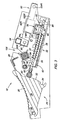
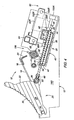
- FIGS. 1 and 2 of the drawings there is shown a crop cutting device 10 which is adapted for use in conjunction with crop harvesting implements such as large round or square balers or forage harvesters or forage wagons, or any other implement equipped with a crop pick-up for elevating a windrow of crop from the ground and conveying it for being processed further and/or loaded in a container.
- the crop cutting device is located so that picked up crop flows over the top of the cutting device as it is propelled toward further crop processing elements by a crop feed rotor which cooperates with the crop cutting device 10, in a manner described below, so as to reduce the size of the crop material being conveyed.
- the crop cutting device 10 includes a support frame 12 comprising identical, right- and left-hand, transversely spaced, vertical side walls 14R and 14L, respectively. Extending between an upper forward section of the side walls 14R and 14L is a formed sheet defining an upwardly and rearwardly inclined knife bed 16 which is provided with a plurality of transversely spaced slots 18. Providing stiffness to the frame 12 is a transverse, horizontal angle member 20 having one leg located beneath, and fixed to, an upper end region of the knife bed 16, and having opposite ends respectively fixed to inner surfaces of the side walls 14R and 14L.
- a knife assembly 24 is mounted beneath the knife bed 16.
- the knife assembly 24 includes a plurality of identical, generally triangular knives 26, which are respectively located within the slots 18. Forward corners of the knives 26 are pivotally mounted to a cylindrical rod 28 that extends through, and is fixed to the side walls 14 at a location just below forward end regions of the slots 18.
- the knives 26 may individually pivot about the rod 28 between a lowered, non-working or inactive position, wherein a serrated cutting edge 30, which extends between the lower front corner and an upper rear corner of the knife, is located approximately at the level of the knife bed 16, and a raised, working or active position, wherein the cutting edge 30 is angled up and to the rear above the knife bed 16.
- Each knife 26 has a rear edge defining a cam surface 32 extending between the upper rear corner and a lower rear corner and which terminates at a semi-circular recess 34 located at the lower rear corner.
- a safety trip mechanism 36 comprising several safety trip devices and including a support plate 38 which extends between and is fixed to the side walls 14R and 14L of the frame 12, and is angled upwardly toward the front from a lower rear corner of the side walls.
- a support plate 38 mounted to the top of the support plate 38 in fore-and-aft or longitudinal alignment with each of the knives 26 is an elongate U-shaped support bracket 40 having upwardly projecting, front and rear legs 42 and 44, respectively.
- the legs 42 and 44 contain fore-and-aft aligned apertures which receive an elongate spring support rod 46 for fore-and-aft sliding movement.
- a roller support member 48 Mounted to the front of the rod 46 is a roller support member 48 to which a roller 50 is mounted for rotation about a horizontal axis.
- the roller 50 is located in the semi-circular recess 34.
- a coil compression spring 52 is received on the spring support rod 46 between the front and rear legs 42 and 44 of the bracket 36, with a rear end of the spring 52 engaging the rear leg 44 and with a forward end of the spring 52 engaging a washer 54 positioned against roll pin 56 extending cross wise through the support rod 46 at a location just to the rear of the front leg 42 of the support bracket 40 when the roller 50 is located in the recess 34.
- the spring 52 when a pre-selected force is exerted on the cutting edge 30 of the knife 26, the spring 52 will yield and permit the roller 50 to move out of the recess 34 so as to permit the knife 26 to pivot downwardly to its non-working position shown in FIG. 3 . Once the force which caused the knife 26 to move to its non-working position is removed, the spring 52 will unload and cause the knife 26 to be restored to its working position.
- a knife control mechanism 60 is provided for permitting an operator to remotely establish working or non-working conditions in the blades 26.
- the control mechanism 60 includes right- and left-hand, extensible and retractable hydraulic cylinders 62R and 62L.
- an anchor structure including a horizontal, transverse cross member 64 extending between, and having opposite ends respectively fixed to, the side walls 14R and 14L at locations spaced rearwardly from the angle member 20.
- the cross member 64 is square in cross section and fixed to rear and bottom surfaces of right- and left-hand end regions of the cross member 64 are right- and left-hand pairs of transversely spaced plates 66R and 66L.
- the head end of the cylinder 62R is received between and pinned, as at 68, to the spaced pair of plates 66R.
- the head end of the cylinder 62L is received between and pinned to the pair of plates 66L.
- a cross member 74 defined by an inverted U-shaped channel member extending transversely between the side walls 14R and 14L and having front and rear legs 76 and 78, respectively.
- a clearance notch 80 is provided in a lower edge of the front leg 76 and extends across all except opposite end regions of the leg 76 so as to provide clearance for the spring support rods 46 and the springs 52.
- Guide notches 82 are provided across a bottom edge of the rear leg 78, and located in each notch 82 is one of the guide rods 46.
- Located in a rear end region of each spring support rod 46 is a rear roll pin 84 having a length greater than the width of the notches 82 so as to be in a path of rearward travel of the cross member 74, for a reason stated below.
- a pair of front apertures 86R and 86L are respectively provided in the front leg 76 at opposite end locations which are respectively in axial alignment with a pair of rear apertures 88R and 88L provided in the rear leg 78.
- a bearing sleeve 90 Positioned within each of the apertures 86R, 86L, 88R, 88L is a bearing sleeve 90 having an enlarged head 92 located in engagement with an inner surface of the associated leg 76 or 78.
- a keeper pin Provided in each of the bearing sleeves 90 at a location adjacent an outer surface of the associated leg 76 or 78 is a keeper pin which cooperates with the head 92 so as to hold the bearing sleeve 90 in place in the associated leg. As can best be seen in FIG.
- right-and left-hand guide rods 96R and 96L are respectively received in each pair of axially aligned bearing sleeves 90.
- the guide rod 96R has front and rear end portions respectively fixed within front and rear bracket assemblies and 98R and 100R that are in turn fixed to the support plate 38.
- the guide rod 96L has front and rear end portions respectively fixed within front and rear bracket assemblies 98L and 100L that are in turn fixed to the support plate 38.
- Fixed to a right-hand end region of the cross member 74 are a transversely spaced pair of cylinder mounting plates 102R that are respectively in fore-and-aft alignment with the pair of plates 66R.
- a mounting pin 104R couples the rod end of the hydraulic cylinder 62R to the pair of mounting plates 102R.
- a transversely spaced pair of cylinder mounting plates 102L are fixed to a left-hand end region of the cross member 74, and a mounting pin 104L couples the rod end of the hydraulic cylinder 62L to the pair of mounting plates 102L.
- a knife selecting arrangement 106 is provided for the purpose of blocking out certain knives 26 so that they remain in an inactive or non-working position even when the cylinders 62R and 62L are retracted.
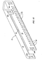
- the knife selecting arrangement 106 is defined by a selector rotor 108 comprising a cylindrical tube 110 and stub shafts 112R and 112L respectively fixed to the opposite ends of the tube 110.
- the stub shafts 112R and 112L are of a smaller diameter than the tube 110 and are respectively received in clearance slots 114R and 114L provided in upper edges of the side walls 14R and 14L at locations spaced just to the rear of the angle member 20.
- four different tab arrangements 116, 118, 120 and 122 are respectively fixed to the tube 110 in longitudinal rows spaced equally from each other about the longitudinal axis of the tube 110.
- the tab arrangement 116 is designed for blocking all of the spring mounting rods 46 in the retracted position, as shown in FIG. 6 , so that none of the knives 26 are operative for cutting crop.
- the tab arrangement includes a pair of tabs 124 respectively located at opposite extremes of the arrangement 116, and located between the tabs 124 and cooperating with the tabs 124 and with each other for defining a plurality of spaces 126 equal to the number of spring support rods 46 are a plurality of double-tabs 128.
- the spaces 126 are each dimensioned to permit one spring support rod 46 to pass through them but not the pin 84 carried by the rod 46.
- the tab arrangement 118 is designed for blocking every other one of the spring mounting rods 46 in the retracted position shown in FIG. 6 , beginning with the spring mounting rods 46 at the outer end. Since there are twenty-three knives 26 in the present embodiment, twelve are blocked and eleven remain operative for cutting crop. To accomplish this, the arrangement 118 includes a plurality of the tabs 124 spaced from each other so as to define spaces 126 at the opposite ends of the arrangement followed by double-spaces 130, with each of the double-spaces 130 being dimensioned for permitting one of the rods 46 and the pin 84 carried by it to pass through it.
- the tab arrangement 120 is designed with a pattern similar to that of the tab arrangement 118 however the arrangement 120 is shortened so as not to block the outer rods 46 and is staggered relative to the arrangement 118 so as to block those rods not blocked by the arrangement 118. Thus, this results in an arrangement for blocking eleven knives 26 from operation while permitting twelve to be operative for cutting crop.
- the tab arrangement 122 is designed with a pattern, beginning at the right- hand side of the safety trip mechanism 36, for blocking the first two spring support rods 46, leaving the next one free and then blocking the next two and so on until the left-hand end of the mechanism 36 is reached wherein the arrangement 122 is shortened so that only the next to the last cutting knife is blocked from operation. This is accomplished by starting with a tab 124 followed by a double-tab 128 and then another tab 124 followed by a double-space and then a repeat of the tab pattern until the right-hand end where two tabs 124 separated by a space 126 form the end of the tab arrangement 122. With this arrangement, fifteen knives 26 are blocked from operation, leaving eight operative for cutting crop.
- the number of cutting knives 26 can vary depending on the size of the baler, or other factors, and that a selector mechanism 106 may be provided with rotors having any desired number of rows and tab patterns for achieving a desired crop cutting characteristic with the cutting device 10.
- the lower portions of the clearance slots 114R and 114L are formed at a radius about a horizontal, transverse axis defined by transverse mounting pins 130R and 130L that are secured within respective holes provided in the side walls 14R and 14L at locations just below rear regions of the hydraulic cylinders 62R and 62L.
- the mounting pins 130R and 130L respectively project outwardly from the side walls 14R and 14L and respectively mounted for pivoting vertically about the pins 130R and 130L are right- and left-hand, oval-shaped mounting plates 132R and 132L having respective rear ends mounted on the pins.
- the mounting plates 132R and 132L have respective central regions in which the stub shafts 112R and 112L of the selector rotor 108 are mounted for rotation about a central axis of the rotor.
- Fixed to the outer ends of the stub shafts 112R and 112L are circular indexing discs, of which only the left-hand disc 136 is shown.
- a handle 138 is fixed to the disc 136 in a location diametrically opposite from a spring-loaded pin device 140 which locks the selector rotor 108 in a desired rotational position by being inserted in a selected one of four holes 142 provided in the mounting plate 132L at equally spaced locations about the longitudinal axis of the rotor 108.
- a further spring-loaded pin device 144 is mounted to a forward region of the mounting plate 132L and serves, when located in a lower hole 146 provided in the side wall 14L, to lock the selector device 106 in a lowered working position, as shown in FIGS. 6 and 7 , and serves, when located in an upper hole 148 provided in the side wall 14L, to lock the selector device in a raised non-working position, as shown in FIGS. 3-5 .
- selector mechanism 106 The operation of the selector mechanism 106 will now be described. Assuming that the selector mechanism 106 is in its lowered working position, shown in FIGS. 6 and 7 , and that it is desired to change the number of active knives 26, it is first necessary for all of the knives 26 to be placed in their lowered, inactive positions. This is accomplished by actuating the knife control cylinders 62R and 62L to their extended positions, shown in FIG. 3 .
- Extension of the cylinders 62R and 62L causes the cross member 74 to be moved to the rear resulting in the pins 84 being engaged and the spring support rods 46 being shifted to the rear against the bias of the springs 52 so as to remove the rollers 50 from the recesses 34 in the active knives 26 so as to permit the latter to fall to their inoperative positions, shown in FIG. 3 .
- the pins 56 respectively associated with any spring mounting rod 46 that had previously been blocked by the selected tab arrangement, are then free of the selector rotor 108.
- the selector rotor 108 is then raised to its inoperative position (see FIG.
- the knives associated with the unblocked spring mounting rods 46 are then moved to their active positions by actuating the cylinders 62R and 62L so they retract to establish the condition illustrated in FIG. 6 wherein the blocked mounting rods 46 remain in their rearward positions while the remaining rods 46 are shifted forwardly by the springs 52 and cause the selected knives 26 to be pivoted upwardly to their active positions.
Landscapes
- Life Sciences & Earth Sciences (AREA)
- Environmental Sciences (AREA)
- Harvester Elements (AREA)
- Threshing Machine Elements (AREA)
Claims (5)
- Erntegutschneidmaschine (10) mit einem Stützrahmen (12), der sich gegenüberliegende Seitenwände (14R, 14L) hat, einem Messerbett (16), das sich zwischen den Seitenwänden (14R, 14L) erstreckt und mit mehreren parallelen, länglichen Schlitzen (18) versehen ist, die sich in einer Bewegungsrichtung des Messerbetts (16) erstrecken, und mehreren Messern (26), die unter dem Messerbett (16) jeweils in vertikaler Ausrichtung zu den länglichen Schlitzen (18) und zum vertikalen Schwenken zwischen einer abgesenkten Nicht-Arbeitsposition, in der Schneidkanten der Messer (26) im Wesentlichen an den länglichen Schlitzen (18) angeordnet sind, und einer angehobenen Arbeitsposition montiert sind, in der die Schneidkanten im Wesentlichen gänzlich über das Messerbett (16) vorragen, einer Sicherheitsabschaltvorrichtung, die jedem Messer (26) zugeordnet ist und ein federnd nachgiebiges Glied (52) aufweist, das zwischen einer ausgefahrenen Position, in der es ein zugeordnetes Messer (26) in seiner Arbeitsposition hält, und einer nachgegebenen eingezogenen Position beweglich ist, in der es dem zugeordneten Messer (26) gestattet ist, sich in seine Nicht-Arbeitsposition zu bewegen, und einem Auswählmechanismus zum gezielten Blockieren gewisser Sicherheitsabschaltvorrichtungen in ihren eingezogenen Positionen, wobei der Auswählmechanismus einen drehbar montierten Rotor (108) aufweist, der sich benachbart zu den Sicherheitsabschaltvorrichtungen erstreckt und mindestens zwei verschiedene Auswählanordnungen (106) hat, die gezielt in Positionen zum Blockieren unterschiedlicher Anzahlen der Sicherheitsabschaltvorrichtungen in ihren jeweiligen eingezogenen Positionen bewegbar sind, dadurch gekennzeichnet, dass der Rotor (108) zur Bewegung in eine Nicht-Gebrauchsposition montiert ist, die von den Sicherheitsabschaltvorrichtungen beabstandet ist, damit dadurch allen Sicherheitsabschaltvorrichtungen gestattet ist, sich zwischen ihren ausgefahrenen und eingezogenen Positionen zu bewegen.
- Schneidvorrichtung nach Anspruch 1, gekennzeichnet durch einen angetriebenen Mechanismus zum Bewegen aller Sicherheitsabschaltvorrichtungen in ihre eingezogene Position vor dem Betrieb des Auswählmechanismus, um vorausgewählte der Sicherheitsabschaltvorrichtungen gezielt in ihren eingezogenen Positionen zu blockieren.
- Schneidvorrichtung nach Anspruch 1 oder 2, gekennzeichnet durch einen angetriebenen Mechanismus, der betriebsmäßig an die mehreren Sicherheitsabschaltvorrichtungen gekoppelt ist, um alle Sicherheitsabschaltvorrichtungen, außer den durch den Auswählmechanismus blockierten, in ihre ausgefahrenen Positionen zu bewegen.
- Schneidvorrichtung nach einem oder mehreren der vorhergehenden Ansprüche, dadurch gekennzeichnet, dass die Sicherheitsabschaltvorrichtungen jeweils einen länglichen Stab (46) aufweisen, der einen Anschlag wie einen Stift (84) hat, der entlang seiner Länge angeordnet ist, und dass die Auswählanordnungen jeweils durch Auswählnasen (124, 128) definiert sind, die angeordnet sind, um den Anschlag ausgewählter der Sicherheitsvorrichtungen in Eingriff zu nehmen, um eine Bewegung des länglichen Stabs (46) zu verhindern.
- Landwirtschaftliche Maschine mit einer Pickup- und einer Schneidvorrichtung nach einem oder mehreren der vorhergehenden Ansprüche.
Applications Claiming Priority (2)
| Application Number | Priority Date | Filing Date | Title |
|---|---|---|---|
| US877273 | 2004-06-25 | ||
| US10/877,273 US6912835B1 (en) | 2004-06-25 | 2004-06-25 | Knife selecting arrangement of crop cutting device for use with agricultural machines having a pick-up |
Publications (3)
| Publication Number | Publication Date |
|---|---|
| EP1609354A2 EP1609354A2 (de) | 2005-12-28 |
| EP1609354A3 EP1609354A3 (de) | 2006-01-04 |
| EP1609354B1 true EP1609354B1 (de) | 2011-04-20 |
Family
ID=34701540
Family Applications (1)
| Application Number | Title | Priority Date | Filing Date |
|---|---|---|---|
| EP05105289A Ceased EP1609354B1 (de) | 2004-06-25 | 2005-06-16 | Schneidvorrichtung und landwirtschaftliche Maschine mit einer solchen Schneidvorrichtung |
Country Status (3)
| Country | Link |
|---|---|
| US (1) | US6912835B1 (de) |
| EP (1) | EP1609354B1 (de) |
| DE (1) | DE602005027519D1 (de) |
Families Citing this family (29)
| Publication number | Priority date | Publication date | Assignee | Title |
|---|---|---|---|---|
| US7553225B2 (en) * | 2007-05-23 | 2009-06-30 | Cnh America Llc | Knife blade covers for a rotary chopper element of an integral chopper assembly of a combine harvester for converting the integral chopper assembly to a beater construction |
| US7993187B2 (en) * | 2007-05-23 | 2011-08-09 | Cnh America Llc | Foreign object detection and removal system for a combine harvester |
| US7867072B2 (en) | 2009-03-13 | 2011-01-11 | Cnh America Llc | Rotor tine and rotary element configuration for crop residue treatment systems |
| DE102012007634A1 (de) | 2012-04-18 | 2013-10-24 | Usines Claas France S.A.S. | Schneidvorrichtung für landwirtschaftliches Erntegut |
| US9137949B2 (en) | 2012-12-26 | 2015-09-22 | Cnh Industrial America Llc | Chopper assembly for harvesting equipment |
| US8920227B2 (en) | 2013-01-02 | 2014-12-30 | Cnh Industrial America Llc | Spring loaded counter knife bank assembly |
| DE102013007302B4 (de) * | 2013-04-26 | 2022-08-25 | Pöttinger Landtechnik Gmbh | Schneidwerk für eine Erntegutverarbeitungsmaschine |
| DE102013007304B4 (de) * | 2013-04-26 | 2016-01-14 | Alois Pöttinger Maschinenfabrik Ges.m.b.H. | Schneidwerk für eine Erntemaschine |
| DE102013108292A1 (de) * | 2013-08-01 | 2015-02-05 | Claas Selbstfahrende Erntemaschinen Gmbh | Mähdrescher mit einer Häckselvorrichtung |
| DE202014006083U1 (de) * | 2014-07-30 | 2015-11-04 | Maschinenfabrik Bernard Krone Gmbh | Schneideinrichtung für landwirtschaftliche Erntemaschinen |
| US9913433B2 (en) | 2015-01-30 | 2018-03-13 | Cnh Industrial America Llc | Selectable knife tray arrangement |
| BE1023152B1 (nl) | 2015-08-28 | 2016-12-02 | Cnh Industrial Belgium Nv | Oogstmachine met feedbackregeling van hakselparameters |
| US10462974B2 (en) | 2016-07-27 | 2019-11-05 | Deere & Company | Two stage knife floor |
| DE102016120528B4 (de) * | 2016-10-27 | 2019-02-07 | B. Strautmann & Söhne GmbH u. Co. KG | Schneidmesser-Überlastsicherung |
| BE1026646B1 (nl) | 2018-09-25 | 2020-04-27 | Cnh Ind Belgium Nv | Gewassnijtoestel,landbouwmachine die zulk gewassnijtoestel bevat en werkwijze om het mes te verwijderen |
| BE1026645B1 (nl) | 2018-09-25 | 2020-04-27 | Cnh Ind Belgium Nv | Gewassnijtoestel, landbouwmachine die zulk gewassnijtoestel bevat en werkwijze om gewas te snijden |
| DE102019005937A1 (de) * | 2019-03-21 | 2020-09-24 | Maschinenfabrik Bernard Krone GmbH & Co. KG | Schneidvorrichtung |
| EP3847886B1 (de) * | 2020-01-10 | 2023-08-23 | CNH Industrial Belgium N.V. | Erntegutschneidvorrichtung mit rotormesser-einsetzhilfsvorrichtung |
| US11632911B2 (en) | 2020-02-14 | 2023-04-25 | Cnh Industrial America Llc | Agricultural baler with knife overload mitigating system |
| US11576309B2 (en) * | 2020-02-27 | 2023-02-14 | Cnh Industrial America Llc | System and method for cleaning a cutting assembly of an agricultural baler |
| US11672207B2 (en) * | 2020-03-02 | 2023-06-13 | Cnh Industrial America Llc | Agricultural vehicle with guided rotor knives |
| US12414507B2 (en) | 2021-11-24 | 2025-09-16 | Cnh Industrial America Llc | Knife insert and retract with independent knife protection of agricultural baler |
| US12336453B2 (en) | 2021-12-29 | 2025-06-24 | Cnh Industrial America Llc | Knife insert and retract with independent knife protection of agricultural baler |
| DE102022103539B3 (de) * | 2022-02-15 | 2023-06-29 | Pöttinger Landtechnik Gmbh | Erntemaschine sowie Verfahren zu deren Herstellung |
| EP4275480B1 (de) | 2022-05-10 | 2025-07-16 | CNH Industrial Belgium N.V. | Erntegutschneidevorrichtung |
| EP4282253B1 (de) | 2022-05-23 | 2025-03-19 | CNH Industrial Belgium N.V. | Erntegutschneidevorrichtung |
| GB2625328A (en) * | 2022-12-14 | 2024-06-19 | Kuhn Geldrop Bv | Cutter device for an agricultural harvester |
| US20240224877A1 (en) * | 2023-01-05 | 2024-07-11 | Deere & Company | Large square baler with controllable feeder system |
| EP4666840A1 (de) | 2024-06-21 | 2025-12-24 | CNH Industrial Belgium N.V. | Erntegutschneidevorrichtung |
Family Cites Families (9)
| Publication number | Priority date | Publication date | Assignee | Title |
|---|---|---|---|---|
| DE3245596A1 (de) * | 1982-12-09 | 1984-06-14 | Claas Saulgau GmbH, 7968 Saulgau | Schneidvorrichtung im foerderschacht eines ladewagens |
| DE8631062U1 (de) * | 1986-11-20 | 1988-03-17 | Karl Mengele & Söhne Maschinenfabrik und Eisengießerei GmbH & Co, 8870 Günzburg | Schneidwerk für Ladewagen |
| DE3816204A1 (de) * | 1988-05-11 | 1989-11-16 | Greenland Gmbh & Co Kg | Grossballenpresse |
| DE4302199C2 (de) * | 1993-01-27 | 1997-09-04 | Claas Ohg | Schneidwerk für landwirtschaftliche Erntemaschinen |
| DE19706429C1 (de) * | 1997-02-19 | 1998-04-16 | Fortschritt Erntemaschinen | Schneideinrichtung für landwirtschaftliche Erntemaschinen |
| DE19805854C1 (de) | 1998-02-13 | 1999-05-12 | Claas Usines France | Schalteinrichtung für Schneidmesser |
| DE19832463C2 (de) | 1998-07-18 | 2002-07-04 | Krone Bernhard Gmbh Maschf | Schneideinrichtung für landwirtschaftliche Erntemaschinen |
| DE19905835C2 (de) | 1999-02-12 | 2003-04-17 | Usines Claas France St Remy Wo | Hydraulische Stelleinrichtung |
| US6769239B1 (en) * | 2003-03-07 | 2004-08-03 | New Holland North America, Inc. | Non-trash sensitive rotor knife guide plates |
-
2004
- 2004-06-25 US US10/877,273 patent/US6912835B1/en not_active Expired - Lifetime
-
2005
- 2005-06-16 DE DE602005027519T patent/DE602005027519D1/de not_active Expired - Lifetime
- 2005-06-16 EP EP05105289A patent/EP1609354B1/de not_active Ceased
Also Published As
| Publication number | Publication date |
|---|---|
| EP1609354A3 (de) | 2006-01-04 |
| DE602005027519D1 (de) | 2011-06-01 |
| EP1609354A2 (de) | 2005-12-28 |
| US6912835B1 (en) | 2005-07-05 |
Similar Documents
| Publication | Publication Date | Title |
|---|---|---|
| EP1609354B1 (de) | Schneidvorrichtung und landwirtschaftliche Maschine mit einer solchen Schneidvorrichtung | |
| EP3628144B1 (de) | Ernteschneidwerk, landwirtschaftsmachine mit einem solchen ernteschneidwerk und ernteschneidmethode | |
| EP2979535B1 (de) | Schneideinrichtung für landwirtschaftliche erntemaschinen | |
| EP2653025B1 (de) | Schneidvorrichtung für landwirtschaftliches Erntegut | |
| US6769239B1 (en) | Non-trash sensitive rotor knife guide plates | |
| WO2012167219A2 (en) | Rubber torsion spring and cushion to protect cutter knives in baler | |
| DE102013007304B4 (de) | Schneidwerk für eine Erntemaschine | |
| US6050510A (en) | Switching device for cutter blades in agricultural harvesting machines | |
| EP4205534A1 (de) | Messereinsatz und einzug mit unabhängigem messerschutz einer landwirtschaftlichen ballenpresse | |
| US20110232246A1 (en) | Device for Erecting Stalk Crop | |
| EP4186351B1 (de) | Messer einschieben und rückziehen mit unabhängigem messerschutz einer landwirtschaftlichen ballenpresse | |
| EP2659761B1 (de) | Erntemaschine mit einer Schneidvorrichtung | |
| CA2967318A1 (en) | Straw buncher | |
| EP3847886B1 (de) | Erntegutschneidvorrichtung mit rotormesser-einsetzhilfsvorrichtung | |
| AU2020284151A1 (en) | Baler with knife protection system | |
| US12041877B2 (en) | Crop cutting device, agricultural machine comprising such crop cutting device and knife removal method | |
| US6810653B2 (en) | Crop pick-up arrangement and height gauge arrangement | |
| GB2055557A (en) | Cutting mechanism for agricultural harvesting machines | |
| EP3092890A1 (de) | Schneidwerk für eine erntemaschine | |
| EP4275480B1 (de) | Erntegutschneidevorrichtung | |
| DE19617033C2 (de) | Schneidwerk für / an landwirtschaftlichen Erntefahrzeugen | |
| US10028440B2 (en) | Bale turning apparatus for a bale processor | |
| US20260000030A1 (en) | Crop cutting device | |
| DE202023100745U1 (de) | Schneidwerk für halmförmiges landwirtschaftliches Erntegut |
Legal Events
| Date | Code | Title | Description |
|---|---|---|---|
| PUAI | Public reference made under article 153(3) epc to a published international application that has entered the european phase |
Free format text: ORIGINAL CODE: 0009012 |
|
| PUAL | Search report despatched |
Free format text: ORIGINAL CODE: 0009013 |
|
| AK | Designated contracting states |
Kind code of ref document: A2 Designated state(s): AT BE BG CH CY CZ DE DK EE ES FI FR GB GR HU IE IS IT LI LT LU MC NL PL PT RO SE SI SK TR |
|
| AX | Request for extension of the european patent |
Extension state: AL BA HR LV MK YU |
|
| AK | Designated contracting states |
Kind code of ref document: A3 Designated state(s): AT BE BG CH CY CZ DE DK EE ES FI FR GB GR HU IE IS IT LI LT LU MC NL PL PT RO SE SI SK TR |
|
| AX | Request for extension of the european patent |
Extension state: AL BA HR LV MK YU |
|
| 17P | Request for examination filed |
Effective date: 20060704 |
|
| AKX | Designation fees paid |
Designated state(s): DE FR GB |
|
| 17Q | First examination report despatched |
Effective date: 20060809 |
|
| GRAP | Despatch of communication of intention to grant a patent |
Free format text: ORIGINAL CODE: EPIDOSNIGR1 |
|
| GRAS | Grant fee paid |
Free format text: ORIGINAL CODE: EPIDOSNIGR3 |
|
| GRAA | (expected) grant |
Free format text: ORIGINAL CODE: 0009210 |
|
| AK | Designated contracting states |
Kind code of ref document: B1 Designated state(s): DE FR GB |
|
| REG | Reference to a national code |
Ref country code: GB Ref legal event code: FG4D |
|
| REF | Corresponds to: |
Ref document number: 602005027519 Country of ref document: DE Date of ref document: 20110601 Kind code of ref document: P |
|
| REG | Reference to a national code |
Ref country code: DE Ref legal event code: R096 Ref document number: 602005027519 Country of ref document: DE Effective date: 20110601 |
|
| PLBE | No opposition filed within time limit |
Free format text: ORIGINAL CODE: 0009261 |
|
| STAA | Information on the status of an ep patent application or granted ep patent |
Free format text: STATUS: NO OPPOSITION FILED WITHIN TIME LIMIT |
|
| 26N | No opposition filed |
Effective date: 20120123 |
|
| REG | Reference to a national code |
Ref country code: DE Ref legal event code: R097 Ref document number: 602005027519 Country of ref document: DE Effective date: 20120123 |
|
| REG | Reference to a national code |
Ref country code: FR Ref legal event code: PLFP Year of fee payment: 12 |
|
| REG | Reference to a national code |
Ref country code: FR Ref legal event code: PLFP Year of fee payment: 13 |
|
| PGFP | Annual fee paid to national office [announced via postgrant information from national office to epo] |
Ref country code: FR Payment date: 20170627 Year of fee payment: 13 Ref country code: GB Payment date: 20170627 Year of fee payment: 13 |
|
| PGFP | Annual fee paid to national office [announced via postgrant information from national office to epo] |
Ref country code: DE Payment date: 20180521 Year of fee payment: 14 |
|
| GBPC | Gb: european patent ceased through non-payment of renewal fee |
Effective date: 20180616 |
|
| PG25 | Lapsed in a contracting state [announced via postgrant information from national office to epo] |
Ref country code: GB Free format text: LAPSE BECAUSE OF NON-PAYMENT OF DUE FEES Effective date: 20180616 Ref country code: FR Free format text: LAPSE BECAUSE OF NON-PAYMENT OF DUE FEES Effective date: 20180630 |
|
| REG | Reference to a national code |
Ref country code: DE Ref legal event code: R119 Ref document number: 602005027519 Country of ref document: DE |
|
| PG25 | Lapsed in a contracting state [announced via postgrant information from national office to epo] |
Ref country code: DE Free format text: LAPSE BECAUSE OF NON-PAYMENT OF DUE FEES Effective date: 20200101 |