EP1608041A2 - A connector for an electric/electronic device and a method of assembling it - Google Patents
A connector for an electric/electronic device and a method of assembling it Download PDFInfo
- Publication number
- EP1608041A2 EP1608041A2 EP05012665A EP05012665A EP1608041A2 EP 1608041 A2 EP1608041 A2 EP 1608041A2 EP 05012665 A EP05012665 A EP 05012665A EP 05012665 A EP05012665 A EP 05012665A EP 1608041 A2 EP1608041 A2 EP 1608041A2
- Authority
- EP
- European Patent Office
- Prior art keywords
- press
- hole
- connector
- fit
- circuit board
- Prior art date
- Legal status (The legal status is an assumption and is not a legal conclusion. Google has not performed a legal analysis and makes no representation as to the accuracy of the status listed.)
- Granted
Links
- 238000000034 method Methods 0.000 title claims description 7
- 230000013011 mating Effects 0.000 claims description 21
- 230000036544 posture Effects 0.000 claims description 11
- 230000000149 penetrating effect Effects 0.000 description 3
- 230000006835 compression Effects 0.000 description 2
- 238000007906 compression Methods 0.000 description 2
- 238000003780 insertion Methods 0.000 description 2
- 230000037431 insertion Effects 0.000 description 2
- 238000010276 construction Methods 0.000 description 1
- 230000001419 dependent effect Effects 0.000 description 1
- 239000002184 metal Substances 0.000 description 1
- 230000000717 retained effect Effects 0.000 description 1
- 229920003002 synthetic resin Polymers 0.000 description 1
- 239000000057 synthetic resin Substances 0.000 description 1
Images






Classifications
-
- H—ELECTRICITY
- H01—ELECTRIC ELEMENTS
- H01R—ELECTRICALLY-CONDUCTIVE CONNECTIONS; STRUCTURAL ASSOCIATIONS OF A PLURALITY OF MUTUALLY-INSULATED ELECTRICAL CONNECTING ELEMENTS; COUPLING DEVICES; CURRENT COLLECTORS
- H01R13/00—Details of coupling devices of the kinds covered by groups H01R12/70 or H01R24/00 - H01R33/00
- H01R13/62—Means for facilitating engagement or disengagement of coupling parts or for holding them in engagement
- H01R13/639—Additional means for holding or locking coupling parts together, after engagement, e.g. separate keylock, retainer strap
-
- H—ELECTRICITY
- H01—ELECTRIC ELEMENTS
- H01R—ELECTRICALLY-CONDUCTIVE CONNECTIONS; STRUCTURAL ASSOCIATIONS OF A PLURALITY OF MUTUALLY-INSULATED ELECTRICAL CONNECTING ELEMENTS; COUPLING DEVICES; CURRENT COLLECTORS
- H01R12/00—Structural associations of a plurality of mutually-insulated electrical connecting elements, specially adapted for printed circuits, e.g. printed circuit boards [PCB], flat or ribbon cables, or like generally planar structures, e.g. terminal strips, terminal blocks; Coupling devices specially adapted for printed circuits, flat or ribbon cables, or like generally planar structures; Terminals specially adapted for contact with, or insertion into, printed circuits, flat or ribbon cables, or like generally planar structures
- H01R12/50—Fixed connections
- H01R12/51—Fixed connections for rigid printed circuits or like structures
- H01R12/55—Fixed connections for rigid printed circuits or like structures characterised by the terminals
- H01R12/58—Fixed connections for rigid printed circuits or like structures characterised by the terminals terminals for insertion into holes
- H01R12/585—Terminals having a press fit or a compliant portion and a shank passing through a hole in the printed circuit board
-
- H—ELECTRICITY
- H01—ELECTRIC ELEMENTS
- H01R—ELECTRICALLY-CONDUCTIVE CONNECTIONS; STRUCTURAL ASSOCIATIONS OF A PLURALITY OF MUTUALLY-INSULATED ELECTRICAL CONNECTING ELEMENTS; COUPLING DEVICES; CURRENT COLLECTORS
- H01R13/00—Details of coupling devices of the kinds covered by groups H01R12/70 or H01R24/00 - H01R33/00
- H01R13/40—Securing contact members in or to a base or case; Insulating of contact members
- H01R13/405—Securing in non-demountable manner, e.g. moulding, riveting
- H01R13/41—Securing in non-demountable manner, e.g. moulding, riveting by frictional grip in grommet, panel or base
Definitions
- the present invention relates to a connector to be connected to an electric and/or electronic device such as to a circuit board connector using press-fit terminals, and to a method of assembling it.
- a circuit board connector as shown in FIG. 11 is known as the one of this type.
- a receptacle 2 into which a mating connector is fittable is formed, for example, on the upper surface of a connector housing 1, and a plurality of press-fit terminals 3 each formed with a resilient bulging portion 4 and a press-in portion 6 fitted with a stopper 5 and located above the resilient bulging portion 4 penetrate a bottom wall 2A of this receptacle 2.
- Upper ends of the respective press-fit terminals 3 project into the receptacle 2, and the resilient bulging portions 4 project down from the bottom wall 2A so as to be insertable into corresponding through holes of a printed circuit board for connection.
- a circuit board connector of this type is disclosed in International Publication Pamphlet WO 95/14315.
- the press-fit terminals 3 are retained in their state of penetrating the bottom wall 2A of the housing 1 by being inserted through press-in holes 7 formed in the bottom wall 2A from below to press the press-in portions 6 into the press-in holes 7 until the stoppers 5 come into contact with the edges of the press-in holes 7.
- forces for locking the press-fit terminals 3 tend to decrease in the case that forces act on the press-fit terminals 3 in downward direction, for example, upon fitting the mating connector into the receptacle 2.
- the press-fit terminals 3 may be inserted from above.
- the press-in portions 6 are pressed into the press-in holes 7 after the resilient bulging portions 4 pass through the press-in holes 7, they have to be wider than the resilient bulging portions 4.
- the press-fit terminals 3 are obliged to be widened. Therefore, there has been a problem of restriction in the case of narrowing intervals between the press-fit terminals 3.
- the present invention was developed in view of the above problem and an object thereof is to enable the terminal arrangement at narrower intervals while ensuring sufficient retaining forces.
- a connector for an electric and/or electronic device such as a circuit board, comprising:
- the press-fit terminals are arrangeable or arranged to penetrate side by side the arranging wall of the connecting part such that the rear ends thereof at least partly project into the connecting part and the resilient bulging portions thereof at least partly project toward a side opposite from the connecting part.
- the respective resilient bulging portions are at least partly insertable into corresponding connection holes or recesses of an electric and/or electronic device such as a circuit board for connection.
- a circuit board connector comprising:
- the resilient bulging portion and the press-in portion of each press-fit terminal are formed to bulge out substantially in the same plane.
- each press-fit terminal are formed to bulge out in the same plane and the rotational posture of the press-fit terminal is turned by 90° after the resilient bulging portion passes through the through hole, thereby enabling the press-in portion to be successively pressed into the press-in hole.
- each press-fit terminal is formed to have such postures as to cross each other at substantially right angles.
- the rotational posture of the press-fit terminal is to be turned by an angle different from 0° or 180°, preferably substantially by 90° after the resilient bulging portion passes through the through hole, thereby enabling the press-in portion to be successively pressed into the press-in hole.
- the resilient bulging portion and the press-in portion are formed to bulge out in the substantially same plane in the press-fit terminal, the resilient bulging portion is first inserted through the through hole and then the press-in portion is pressed into the press-in hole after the press-fit terminal is turned by an angle different from 0° or 180°, preferably substantially by 90°.
- the resilient bulging portion and the press-in portion are formed to have such postures as to cross each other at right angles, the resilient bulging portion is first inserted through the through hole and then the press-in portion is pressed into the press-in portion while the press-fit terminal is kept in a specified rotational posture.
- the press-fit terminals are inserted from the side of the connecting part of the connector housing, considerable locking forces act in the case that pushing forces act on the press-fit terminals in inserting direction as the mating connector is fitted into the connecting part. In other words, the press-fit terminals are prevented from escaping when the mating connector is fitted, thereby improving connection reliability between the press-fit terminals and terminals mounted in the mating connector.
- the press-in portions can be made narrower than the resilient bulging portions, i.e. the press-in holes can be made narrower despite the fact that the resilient bulging portion and the press-in portion are successively inserted in this order.
- the press-in holes are formed such that the widthwise direction thereof is aligned with the arranging direction of the press-fit terminals, thereby enabling the intervals of the press-in holes to be narrowed.
- the press-fit terminals can be arranged side by side at narrower intervals.
- the press-in hole has a lateral width between a width of a bar portion of the press-fit terminal and the width of the press-in portion so that the press-in portion can be at least partly pressed thereinto.
- a stopper is formed behind the press-in portion for coming into abutment on a corresponding portion of the connector housing, the stopper preferably having a width which is larger than the maximal width of the resilient bulging portion.
- a method of assembling a connector for an electric and/or electronic device such as a circuit board comprising the following steps:
- the rotational posture of the press-fit terminal is turned or changed by an angle different from 0° or 180°, preferably substantially by 90° after the resilient bulging portion passes through the through hole, thereby enabling the press-in portion to be successively pressed into the press-in hole.
- a circuit board connector of this embodiment (as a preferred connector to be connected with an electric and/or electronic device) is constructed such that one or more, e.g. ten press-fit terminals 10 are at least partly inserted, preferably pressed or fitted into a connector housing 20 (hereinafter, "housing 20") as shown in FIGS. 1 and 2 and is to be mounted on a printed circuit board 30 (as a preferred electric and/or electronic device, see FIG. 9. hereinafter, "circuit board 30").
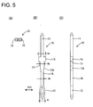
- Each press-fit terminal 10 is preferably formed to have a shape as shown in FIGS. 5(A) to 5(C) by stamping or press-working a conductive (preferably metal) plate having a good electrical conductivity.
- the press-fit terminal 20 substantially is in the form of a narrow and long rectangular bar as a whole, wherein one side (upper side) thereof serves as a terminal connecting portion 11 to be connected with a mating terminal and the leading end is tapered or converging for guiding.
- a resilient bulging portion 12 that serves as a device or board connecting portion to be connected with the circuit board 30 is formed at the other or substantially opposite side (bottom side).
- the resilient bulging portion 12 is so formed as to bulge out laterally, preferably in substantially opposite widthwise directions while forming a hollow in an intermediate portion, preferably substantially in the middle.
- the resilient bulging portion 12 can be resiliently widened and narrowed substantially along widthwise direction WD.
- the resilient bulging portion 12 is or is to be at least partly inserted into a recess or through hole 31 of the circuit board 30 while being resiliently narrowed, and then at least partly widened due to its resilient restoring force to resiliently touch a contact formed on or near at least part of the inner circumferential surface of the through hole 31 as shown in FIG. 9.
- a press-in portion 13 is formed at an intermediate portion between the bulging portion 12 and the terminal connecting portion 11, preferably substantially at a longitudinal middle part of the press-fit terminal 10.
- the press-in portion 13 bulges out preferably substantially in opposite widthwise directions WD, and width w2 thereof is set to be smaller than maximal width w1 of the above resilient bulging portion 12.
- the lateral (left and right) edges of the press-in portion 13 at a bottom side are formed into slanted or rounded or converging edges 13A so that the bottom side is gradually narrowed toward the bottom.
- a stopper 14 is formed (preferably continuously with and) above the press-in portion 13 or on a side of the press-in portion 13 closer to the terminal connecting portion 11. Although the stopper 14 bulges out from the press-in portion 13 to form one or more steps, width w3 thereof is set to be only slightly larger than the maximal width w1 of the resilient bulging portion 12.
- the housing 20 is made e.g. of a synthetic resin, and a receptacle 22 preferably substantially in the form of a rectangular tube having an open (preferably upper) end is formed on the one (preferably upper) surface of a base wall 21.
- An unillustrated mating connector is at least partly fittable into the receptacle 22 from one side, preferably substantially from above. Further, one or more legs 23 to be brought into contact with the outer surface of the circuit board 30 are formed below or at the base wall 21.
- the one or more press-fit terminals 10 are at least partly inserted through the base wall 21 of the housing 20 from an inserting side IS, preferably substantially from above.
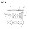
- the base wall 21 is formed with one or more inserting portions 25 for the press-fit terminals 10 at a number of (e.g. five) positions in one or more rows, e.g. in each of two front and rear rows as shown in FIG. 3.
- the inserting portions 25 in each row preferably are arranged at substantially even intervals, wherein those in the front row preferably are substantially aligned with those in the rear row.
- each inserting portion 25 is described in detail.
- the base wall 21 preferably has a thickness slightly larger than a length from the upper end of the stopper 14 of the press-fit terminal 10 to the bottom ends of the slanted edges 13A of the press-in portion 13.
- Each inserting portion 25 includes a through hole 26 for permitting the passage of at least part of the resilient bulging portion 12 of the press-fit terminal 10 and a press-in hole 28 into which the press-in portion 13 is or can be at least partly pressed, both holes 26, 28 penetrating the base wall 21.
- the bar portion 16 may have any other cross-sectional shape such as a rounded or elliptic shape.
- the lateral width Wb is set to be larger than the thickness w0 in order to permit the (preferably substantially rectangular) bar portion 16 to rotate substantially about its longitudinal axis in the through hole 26.
- the through holes 26 are formed such that a direction of the longitudinal width Wa extends at an angle different from 0° or 180°, preferably substantially along a direction normal to an arranging direction AD of the press-fit terminals 10 in each of the front and rear rows, i.e. extends substantially along forward and backward directions.
- a guiding portion 27 At the entrance of each through hole 26, i.e. at the upper opening edge thereof is formed a guiding portion 27 gradually widened toward the upper end.
- each press-in hole 28 has a lateral width Wc between the width w0 of the (preferably substantially rectangular) bar portion 16 of the press-fit terminal 10 and the width w2 of the press-in portion 13 so that the press-in portion 13 can be at least partly pressed thereinto.
- the lateral width Wc of the press-in hole 28 preferably is substantially equal to the lateral width Wb of the aforementioned through hole 26, hence smaller than the longitudinal width Wa of the through hole 26.
- the longitudinal width Wd of the press-in hole 28 preferably is substantially equal to the lateral width Wb of the through hole 26.
- a direction of the lateral width Wc of the press-in hole 28 extends substantially along the arranging direction AD of the press-fit terminals 10 in the connector, preferably in each of the front and rear rows, i.e. along transverse direction.
- An accommodating hole 29 for at least partly accommodating the stopper 14 in contact as shown in FIG. 8(A) is formed at the entrance side of the press-in hole 28.
- a lateral width We of this accommodating hole 29 preferably lies within the lateral width of the guiding portion 27 as also shown in FIG. 3, and/or the depth thereof preferably is such that the upper end of the stopper 14 is in flush with the upper surface of the base wall 21 when the stopper 14 is properly accommodated in the accommodating hole 29 as shown in FIG. 9.
- the press-fit terminal 10 is inserted into the through hole 26 of the corresponding inserting portion 25 from the inserting side IS, preferably substantially from above, with the widthwise direction WD thereof substantially aligned with forward and backward directions as shown in FIG. 2.
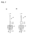
- the resilient bulging portion 12 of the press-fit terminal 10 first passes through the through hole 26 preferably almost without any resilient compression as shown in FIG. 6(B) while being guided, preferably substantially centered, by the guiding portion 27. After the resilient bulging portion 12 comes down or at least partly projects from the through hole 26 as shown in FIG. 7, the press-fit terminal 10 is turned (by an angle different from 0° or 180°, preferably substantially by 90°) about its longitudinal axis and/or about a direction substantially parallel to an inserting direction of the press-fit terminal 10 into the through hole 26.
- the press-in portion 13 At least partly enters the press-in hole 28 and is so pressed as to bite or cut or engage in the (preferably substantially opposite) side walls of the press-in hole 28 with respect to the direction of the lateral width Wc as shown in FIG. 8(A).
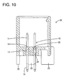
- the pushing is stopped when the stopper 14 comes substantially into contact with the bottom surface of the accommodating hole 29 as shown in FIGS. 9 and 10, whereby the press-fit terminal 10 is mounted while the resilient bulging portion 12 at least partly projects down or outside from the base wall 21 and the terminal connecting portion 11 projects into the receptacle 22 from the other or upper surface of the base wall 21.
- the resilient bulging portions 12 of the respective press-fit terminals 10 are to be at least partly inserted into the corresponding recesses or through holes 31 of the circuit board 30 as shown in FIG. 9 using a jig or the like, thereby resiliently touching the contacts on or at the inner circumferential surfaces to establish electrical connections.
- the legs 23 are secured to the circuit board 30 by securing means such as with screws, press-fitting pins, latches or the like to fix the housing 20 to the circuit board 30.
- the mating connector is or can be at least partly fitted into the receptacle 22 of the housing 20, whereby the terminal connecting portions 11 of the press-fit terminals 10 and mating terminals mounted in the mating connector are connected.
- a pushing force acting in the direction substantially toward the circuit board 30 or downward direction of FIG. 9 is exerted on the press-fit terminals 10.
- the press-fit terminals 10 are prevented from being pushed any further, i.e. do not escape by the contact of the stoppers 14 with the bottom surfaces of the accommodating holes 29. Therefore, the press-fit terminals 10 and the mating terminals mounted in the mating connector are securely connected.
- the press-fit terminal 10 is at least partly inserted and pressed from the inside of the receptacle 22 of the housing 20 and any further insertion thereof is prevented by the contact of the stopper 14 with the bottom surface of the accommodating hole 29.
- a movement of the press-fit terminal 10 in this direction can be securely hindered.
- the press-fit terminals 10 are prevented from escaping when the mating connector is fitted, wherefore the press-fit terminals 10 and the mating terminals mounted in the mating connector can be connected with higher reliability.
- the press-in portion 13 can be made narrower than the resilient bulging portion 12 despite the fact that the resilient bulging portion 12 and the press-in portion 13 are passed through and into the base wall 21 in this order. Further, the stopper 14 wider than the press-in portion 13 can be made as narrow as possible, with the result that the press-in hole 28 including the accommodating hole 29 can be formed to be narrower.
- the press-in holes 28 having a narrower width are formed such that the widthwise direction WD thereof is substantially aligned with the arranging direction AD of the press-fit terminals 10, thereby enabling the intervals of the press-in holes 28 to be narrowed.
- the press-fit terminals 10 can be arranged at narrower intervals.
- one or more (e.g. five) inserting portions 25 into which respective one or more press-fit terminals 10 are at least partly inserted from the inserting side IS, preferably substantially from above, are formed in each of two front and rear rows in a base wall 21 of a housing 20.
- Each inserting portion 25 is formed with a relatively wider through hole 26 for permitting the passage of a resilient bulging portion 12 of the press-fit terminal 10 and a relatively narrower press-in hole 28 into which a press-in portion 13 is pressed, wherein the widthwise direction of the through hole 26 is aligned with a direction normal to an arranging direction of the terminals 10 and the widthwise direction of the press-in hole 28 is aligned with the arranging direction of the terminals 10.
- the resilient bulging portion 12 of the press-fit terminal 10 is first inserted through the through hole 26 and then the press-fit terminal 10 is turned by 90° about its longitudinal axis. Thereafter, the press-in portion 13 is pressed into the press-in hole 28 and the pressing-in is stopped when a stopper 14 comes into contact with the bottom surface of an accommodating hole 29.
Landscapes
- Coupling Device And Connection With Printed Circuit (AREA)
- Multi-Conductor Connections (AREA)
- Manufacturing Of Electrical Connectors (AREA)
- Connector Housings Or Holding Contact Members (AREA)
Abstract
Description
- 10 ...
- press-fit terminal
- 12 ...
- resilient bulging portion
- 13 ...
- press-in portion
- 14 ...
- stopper
- 20 ...
- connector housing
- 21 ...
- base wall (back or arranging wall)
- 22 ...
- receptacle (connecting part)
- 25 ...
- inserting portion
- 26 ...
- through hole
- 28 ...
- press-in hole
- 29 ...
- accommodating hole
- 30 ...
- circuit board (electric and/or electronic device)
Claims (10)
- A connector for an electric and/or electronic device such as a circuit board (30), comprising:wherein a press-in hole (28) which has a relatively short width (Wc) and into which the corresponding press-in portion (13) is pressed and a through hole (26) which has a relatively large width (Wa) and permits the passage of the corresponding resilient bulging portion (12) are formed in an inserting portion (25) for each press-fit terminal (10) in the arranging wall (21) of the connector housing (20) such that the widthwise direction (WD) of the press-in hole (28) is or can be substantially aligned with an arranging direction (AD) of the press-fit terminals (10) and the through hole (26) crosses the press-in hole (28) at an angle different from 0° or 180°, preferably substantially at right angles.a connector housing (20) formed with a connecting part (22) into which a mating connector is at least partly fittable, anda plurality of press-fit terminals (10) each formed with a resilient bulging portion (12) at or near the leading end thereof and a press-in portion (13) provided behind the resilient bulging portion (12) and being arrangeable to penetrate side by side an arranging wall (21) of the connecting part (22),
- A connector for an electric and/or electronic device such as a circuit board (30) according to claim 1, wherein the press-fit terminals (10) are arrangeable to penetrate side by side the arranging wall (21) of the connecting part (22) such that the rear ends thereof at least partly project into the connecting part (22) and the resilient bulging portions (12) thereof at least partly project toward a side opposite from the connecting part (22).
- A connector for an electric and/or electronic device such as a circuit board (30) according to one or more of the preceding claims, wherein the respective resilient bulging portions (12) are at least partly insertable into corresponding connection holes or recesses (31) of an electric and/or electronic device such as a circuit board (30) for connection.
- A connector for an electric and/or electronic device such as a circuit board (30) according to one or more of the preceding claims, wherein the resilient bulging portion (12) and the press-in portion (13) of each press-fit terminal (10) are formed to bulge out substantially in the same plane.
- A connector for an electric and/or electronic device such as a circuit board (30) according to one or more of the preceding claims 1 to 3, wherein the resilient bulging portion (12) and the press-in portion (13) of each press-fit terminal (10) are formed to have such postures as to cross each other at substantially right angles.
- A connector for an electric and/or electronic device such as a circuit board (30) according to one or more of the preceding claims, wherein the rotational posture of the press-fit terminal (10) is to be turned by an angle different from 0° or 180°, preferably substantially by 90° after the resilient bulging portion (12) passes through the through hole (26), thereby enabling the press-in portion (13) to be successively pressed into the press-in hole (25).
- A connector for an electric and/or electronic device such as a circuit board (30) according to one or more of the preceding claims, wherein the press-in hole (28) has a lateral width (Wc) between a width (w0) of a bar portion (16) of the press-fit terminal (10) and the width (w2) of the press-in portion (13) so that the press-in portion (13) can be at least partly pressed thereinto.
- A connector for an electric and/or electronic device such as a circuit board (30) according to one or more of the preceding claims, wherein a stopper (14) is formed behind the press-in portion (13) for coming into abutment on a corresponding portion (29) of the connector housing (20), the stopper (14) preferably having a width (w3) which is larger than the maximal width (w1) of the resilient bulging portion (12).
- A method of assembling a connector for an electric and/or electronic device such as a circuit board (30), comprising the following steps:wherein a press-in hole (28) which has a relatively short width (Wc) and into which the corresponding press-in portion (13) is pressed and a through hole (26) which has a relatively large width (Wa) and permits the passage of the corresponding resilient bulging portion (12) are formed in an inserting portion (25) for each press-fit terminal (10) in the arranging wall (21) of the connector housing (20) such that the widthwise direction (WD) of the press-in hole (28) is or can be substantially aligned with an arranging direction (AD) of the press-fit terminals (10) and the through hole (26) crosses the press-in hole (28) at an angle different from 0° or 180°, preferably substantially at right angles.providing a connector housing (20) formed with a connecting part (22) into which a mating connector is at least partly fittable, andproviding a plurality of press-fit terminals (10) each formed with a resilient bulging portion (12) at or near the leading end thereof and a press-in portion (13) provided behind the resilient bulging portion (12)arranging the press-fit terminals (10) to penetrate side by side an arranging wall (21) of the connecting part (22),
- A method of assembling a connector for an electric and/or electronic device such as a circuit board (30) according to claim 9, wherein the rotational posture of the press-fit terminal (10) is turned by an angle different from 0° or 180°, preferably substantially by 90° after the resilient bulging portion (12) passes through the through hole (26), thereby enabling the press-in portion (13) to be successively pressed into the press-in hole (25).
Applications Claiming Priority (2)
| Application Number | Priority Date | Filing Date | Title |
|---|---|---|---|
| JP2004176571A JP4259405B2 (en) | 2004-06-15 | 2004-06-15 | Board connector |
| JP2004176571 | 2004-06-15 |
Publications (3)
| Publication Number | Publication Date |
|---|---|
| EP1608041A2 true EP1608041A2 (en) | 2005-12-21 |
| EP1608041A3 EP1608041A3 (en) | 2006-04-12 |
| EP1608041B1 EP1608041B1 (en) | 2009-09-09 |
Family
ID=34937404
Family Applications (1)
| Application Number | Title | Priority Date | Filing Date |
|---|---|---|---|
| EP05012665A Expired - Lifetime EP1608041B1 (en) | 2004-06-15 | 2005-06-13 | A connector for an electric/electronic device and a method of assembling it |
Country Status (6)
| Country | Link |
|---|---|
| US (1) | US7037146B2 (en) |
| EP (1) | EP1608041B1 (en) |
| JP (1) | JP4259405B2 (en) |
| KR (1) | KR100708566B1 (en) |
| CN (1) | CN100448105C (en) |
| DE (1) | DE602005016492D1 (en) |
Cited By (2)
| Publication number | Priority date | Publication date | Assignee | Title |
|---|---|---|---|---|
| EP2020703A3 (en) * | 2007-08-02 | 2011-01-12 | Alps Electric Co., Ltd. | Connector terminal holding structure |
| EP2355254A1 (en) * | 2010-02-02 | 2011-08-10 | Wilo Se | Connecting element with knife contact and press fit contact |
Families Citing this family (40)
| Publication number | Priority date | Publication date | Assignee | Title |
|---|---|---|---|---|
| DE102006013281B4 (en) | 2006-03-21 | 2024-04-04 | Erni Production Gmbh & Co. Kg | Plug connection adapter |
| JP2007311092A (en) * | 2006-05-17 | 2007-11-29 | Yazaki Corp | Printed wiring board assembly and method for manufacturing the printed wiring board assembly |
| JP2008053091A (en) * | 2006-08-25 | 2008-03-06 | Honda Tsushin Kogyo Co Ltd | Press-fit contact |
| DE102006040640A1 (en) * | 2006-08-30 | 2008-03-13 | Robert Bosch Gmbh | Insert pin |
| EP2109906B1 (en) * | 2007-02-09 | 2016-09-07 | Johnson Controls Advanced Power Solutions LLC | Buss bar for batteries |
| JP4983387B2 (en) * | 2007-05-16 | 2012-07-25 | 住友電装株式会社 | Board connector |
| JP4924247B2 (en) * | 2007-07-04 | 2012-04-25 | 住友電装株式会社 | connector |
| JP5115149B2 (en) * | 2007-11-02 | 2013-01-09 | 住友電装株式会社 | connector |
| JP2009151940A (en) | 2007-12-18 | 2009-07-09 | Tyco Electronics Amp Kk | Terminal press-fit structure and electric connector |
| JP2009151939A (en) | 2007-12-18 | 2009-07-09 | Tyco Electronics Amp Kk | Terminal press-fit structure and electric connector |
| CN201252219Y (en) * | 2008-07-02 | 2009-06-03 | 富士康(昆山)电脑接插件有限公司 | Electric connector |
| JP2010040257A (en) * | 2008-08-01 | 2010-02-18 | Sumitomo Wiring Syst Ltd | Connector |
| DE102009025113A1 (en) * | 2009-06-11 | 2010-12-16 | Continental Teves Ag & Co. Ohg | Press-in contact for connecting an electronic component to a printed circuit board and press-fit tool |
| US7896655B1 (en) * | 2009-08-14 | 2011-03-01 | Tyco Electronics Corporation | Multi-port connector system |
| JP5387863B2 (en) * | 2011-03-31 | 2014-01-15 | 日本電気株式会社 | Press-fit connector |
| US8727815B1 (en) * | 2012-11-29 | 2014-05-20 | Samtec, Inc. | Compliant pin connector mounting system and method |
| JP2014222976A (en) * | 2013-05-14 | 2014-11-27 | 株式会社オートネットワーク技術研究所 | Electric connection box |
| US20150173181A1 (en) * | 2013-12-16 | 2015-06-18 | Cisco Technology, Inc. | Enlarged Press-Fit Hole |
| KR101519279B1 (en) * | 2013-12-30 | 2015-05-12 | 주식회사 현대케피코 | A device for press fit terminal on PCB and method thereof |
| US9537278B2 (en) * | 2015-02-09 | 2017-01-03 | Yazaki Corporation | Terminal group and connector |
| JP6531438B2 (en) * | 2015-03-13 | 2019-06-19 | オムロン株式会社 | Probe pin and probe unit provided with the same |
| KR101636766B1 (en) | 2015-03-30 | 2016-07-07 | (주)케이블루 | The assembling zig for a multi-pin connecter |
| JP6550890B2 (en) * | 2015-04-22 | 2019-07-31 | 住友電装株式会社 | Press-fit terminal |
| JP2017004859A (en) * | 2015-06-12 | 2017-01-05 | 矢崎総業株式会社 | Connection structure of flat circuit body and connector |
| JP6600261B2 (en) * | 2016-02-10 | 2019-10-30 | 矢崎総業株式会社 | Press-fit terminal |
| DE102016205635A1 (en) * | 2016-04-05 | 2017-10-05 | Continental Automotive Gmbh | connecting element |
| JP7043751B2 (en) * | 2016-10-12 | 2022-03-30 | 株式会社オートネットワーク技術研究所 | Press-fit terminal |
| CN110366876B (en) * | 2017-03-06 | 2023-05-05 | 三菱电机株式会社 | Control unit with press-fit structure |
| US10201087B2 (en) * | 2017-03-30 | 2019-02-05 | Infineon Technologies Austria Ag | Discrete device |
| TWM551357U (en) * | 2017-04-06 | 2017-11-01 | 宣德科技股份有限公司 | Electrical connector |
| CN109504955B (en) * | 2017-09-14 | 2023-06-23 | 深圳市博敏电子有限公司 | Nickel-gold depositing process quick rack inserting device for multilayer circuit board and use method thereof |
| DE102017122591A1 (en) * | 2017-09-28 | 2019-03-28 | Te Connectivity Germany Gmbh | Electrical connection device and sealing arrangement for an electrical connector and method for the production thereof |
| CN109390836B (en) * | 2018-11-23 | 2024-02-13 | 上海雷迪埃电子有限公司 | Assembling tool for bent connector |
| JP7238675B2 (en) * | 2019-07-31 | 2023-03-14 | 住友電装株式会社 | Terminals and board connectors |
| DE102019218205A1 (en) * | 2019-11-25 | 2021-05-27 | Continental Teves Ag & Co. Ohg | Electronics housing for automated assembly |
| CN111628337B (en) | 2020-06-24 | 2021-07-30 | 东莞立讯技术有限公司 | electrical connector |
| CN111628328B (en) * | 2020-06-24 | 2022-02-01 | 东莞立讯技术有限公司 | Electrical connector |
| JP7541050B2 (en) * | 2022-04-28 | 2024-08-27 | 矢崎総業株式会社 | Electronic Component Module |
| KR102617116B1 (en) * | 2023-08-01 | 2023-12-27 | 에스엠일렉트㈜ | connector on circuit board |
| CN220692362U (en) * | 2023-08-18 | 2024-03-29 | 陈俊瑞 | Fish eye terminal structure |
Family Cites Families (10)
| Publication number | Priority date | Publication date | Assignee | Title |
|---|---|---|---|---|
| US5094634A (en) * | 1991-04-11 | 1992-03-10 | Molex Incorporated | Electrical connector employing terminal pins |
| US5453016A (en) * | 1993-11-15 | 1995-09-26 | Berg Technology, Inc. | Right angle electrical connector and insertion tool therefor |
| DE69427235T2 (en) * | 1993-11-15 | 2001-09-27 | Berg Electronics Manufacturing B.V., S'-Hertogenbosch | RIGHT-ANGLE ELECTRIC CONNECTOR AND INSERTION TOOL |
| US5702257A (en) * | 1996-02-29 | 1997-12-30 | The Whitaker Corporation | Electrical connector and terminal therefor |
| US5692928A (en) * | 1996-05-10 | 1997-12-02 | Molex Incorporated | Electrical connector having terminals with improved retention means |
| BE1010707A3 (en) * | 1996-10-23 | 1998-12-01 | Framatome Connectors Belgium | METHOD FOR PRESSING an electrical contact with an elastic CONFIRMATION ZONE IN A HOLE OF A PRINTED WIRING PLATE. |
| US6095826A (en) * | 1997-02-21 | 2000-08-01 | Berg Technology, Inc. | Press fit circuit board connector |
| TW502885U (en) * | 2001-03-02 | 2002-09-11 | Hon Hai Prec Ind Co Ltd | Electrical connector |
| JP2003086277A (en) * | 2001-09-06 | 2003-03-20 | Fujitsu Ltd | Press-fit connection type connector and housing removal device for the connector |
| JP2004031006A (en) * | 2002-06-24 | 2004-01-29 | Sumitomo Wiring Syst Ltd | Mounting structure of terminal and connector for circuit board |
-
2004
- 2004-06-15 JP JP2004176571A patent/JP4259405B2/en not_active Expired - Fee Related
-
2005
- 2005-06-13 DE DE602005016492T patent/DE602005016492D1/en not_active Expired - Lifetime
- 2005-06-13 EP EP05012665A patent/EP1608041B1/en not_active Expired - Lifetime
- 2005-06-15 US US11/153,154 patent/US7037146B2/en not_active Expired - Fee Related
- 2005-06-15 CN CNB2005100764571A patent/CN100448105C/en not_active Expired - Fee Related
- 2005-06-15 KR KR1020050051453A patent/KR100708566B1/en not_active Expired - Fee Related
Cited By (2)
| Publication number | Priority date | Publication date | Assignee | Title |
|---|---|---|---|---|
| EP2020703A3 (en) * | 2007-08-02 | 2011-01-12 | Alps Electric Co., Ltd. | Connector terminal holding structure |
| EP2355254A1 (en) * | 2010-02-02 | 2011-08-10 | Wilo Se | Connecting element with knife contact and press fit contact |
Also Published As
| Publication number | Publication date |
|---|---|
| US20050277312A1 (en) | 2005-12-15 |
| KR20060049217A (en) | 2006-05-18 |
| CN100448105C (en) | 2008-12-31 |
| CN1713455A (en) | 2005-12-28 |
| DE602005016492D1 (en) | 2009-10-22 |
| JP4259405B2 (en) | 2009-04-30 |
| US7037146B2 (en) | 2006-05-02 |
| EP1608041A3 (en) | 2006-04-12 |
| EP1608041B1 (en) | 2009-09-09 |
| KR100708566B1 (en) | 2007-04-19 |
| JP2006004642A (en) | 2006-01-05 |
Similar Documents
| Publication | Publication Date | Title |
|---|---|---|
| EP1608041B1 (en) | A connector for an electric/electronic device and a method of assembling it | |
| JP3041676B2 (en) | Electrical connector with improved terminal retention mechanism | |
| JP3166080B2 (en) | Electrical connector with insertable terminals | |
| EP2164137B1 (en) | A joint connector, joint terminal, a wiring harness with a joint connector and method of assembling it | |
| EP2012394B1 (en) | A connector and an assembling method therefor | |
| US7101228B2 (en) | Electrical connector for memory modules | |
| US4687267A (en) | Circuit board edge connector | |
| EP1562262B1 (en) | A connector and a method of mounting it to an electric device | |
| EP1482594A1 (en) | A terminal | |
| US7033229B2 (en) | Terminal fitting and a connector | |
| US7014511B2 (en) | Electrical connector | |
| EP0682385B1 (en) | Electrical connector | |
| US7431617B2 (en) | Connector | |
| US20090081905A1 (en) | Electrical connector | |
| AU591635B2 (en) | Electrical connector | |
| JP2001155810A (en) | connector | |
| JP2013152841A (en) | Connector device | |
| EP1538706B1 (en) | A connector fixing bracket | |
| JP2003331992A (en) | Sequential connection connector and additional contact used for it | |
| EP1418648B1 (en) | A connector | |
| JPS63138678A (en) | Electric connector | |
| CN109950725A (en) | Electrical connector and electrical connector assembly using the same | |
| JPH11167955A (en) | connector | |
| CN101361232A (en) | electrical connector | |
| CN223815824U (en) | Electric connector assembly |
Legal Events
| Date | Code | Title | Description |
|---|---|---|---|
| PUAI | Public reference made under article 153(3) epc to a published international application that has entered the european phase |
Free format text: ORIGINAL CODE: 0009012 |
|
| 17P | Request for examination filed |
Effective date: 20050623 |
|
| AK | Designated contracting states |
Kind code of ref document: A2 Designated state(s): AT BE BG CH CY CZ DE DK EE ES FI FR GB GR HU IE IS IT LI LT LU MC NL PL PT RO SE SI SK TR |
|
| AX | Request for extension of the european patent |
Extension state: AL BA HR LV MK YU |
|
| PUAL | Search report despatched |
Free format text: ORIGINAL CODE: 0009013 |
|
| AK | Designated contracting states |
Kind code of ref document: A3 Designated state(s): AT BE BG CH CY CZ DE DK EE ES FI FR GB GR HU IE IS IT LI LT LU MC NL PL PT RO SE SI SK TR |
|
| AX | Request for extension of the european patent |
Extension state: AL BA HR LV MK YU |
|
| AKX | Designation fees paid |
Designated state(s): DE FR |
|
| 17Q | First examination report despatched |
Effective date: 20080128 |
|
| GRAP | Despatch of communication of intention to grant a patent |
Free format text: ORIGINAL CODE: EPIDOSNIGR1 |
|
| RIN1 | Information on inventor provided before grant (corrected) |
Inventor name: NAKAMURA, KEIICHI |
|
| GRAS | Grant fee paid |
Free format text: ORIGINAL CODE: EPIDOSNIGR3 |
|
| GRAA | (expected) grant |
Free format text: ORIGINAL CODE: 0009210 |
|
| AK | Designated contracting states |
Kind code of ref document: B1 Designated state(s): DE FR |
|
| REF | Corresponds to: |
Ref document number: 602005016492 Country of ref document: DE Date of ref document: 20091022 Kind code of ref document: P |
|
| PLBE | No opposition filed within time limit |
Free format text: ORIGINAL CODE: 0009261 |
|
| STAA | Information on the status of an ep patent application or granted ep patent |
Free format text: STATUS: NO OPPOSITION FILED WITHIN TIME LIMIT |
|
| 26N | No opposition filed |
Effective date: 20100610 |
|
| REG | Reference to a national code |
Ref country code: FR Ref legal event code: PLFP Year of fee payment: 11 |
|
| PGFP | Annual fee paid to national office [announced via postgrant information from national office to epo] |
Ref country code: DE Payment date: 20150609 Year of fee payment: 11 |
|
| PGFP | Annual fee paid to national office [announced via postgrant information from national office to epo] |
Ref country code: FR Payment date: 20150608 Year of fee payment: 11 |
|
| REG | Reference to a national code |
Ref country code: DE Ref legal event code: R119 Ref document number: 602005016492 Country of ref document: DE |
|
| REG | Reference to a national code |
Ref country code: FR Ref legal event code: ST Effective date: 20170228 |
|
| PG25 | Lapsed in a contracting state [announced via postgrant information from national office to epo] |
Ref country code: FR Free format text: LAPSE BECAUSE OF NON-PAYMENT OF DUE FEES Effective date: 20160630 Ref country code: DE Free format text: LAPSE BECAUSE OF NON-PAYMENT OF DUE FEES Effective date: 20170103 |