EP1607967A1 - Information recording method, information recording device, program, and computer-readable information storage medium - Google Patents
Information recording method, information recording device, program, and computer-readable information storage medium Download PDFInfo
- Publication number
- EP1607967A1 EP1607967A1 EP04719072A EP04719072A EP1607967A1 EP 1607967 A1 EP1607967 A1 EP 1607967A1 EP 04719072 A EP04719072 A EP 04719072A EP 04719072 A EP04719072 A EP 04719072A EP 1607967 A1 EP1607967 A1 EP 1607967A1
- Authority
- EP
- European Patent Office
- Prior art keywords
- writing
- data
- zone
- recording layer
- user data
- Prior art date
- Legal status (The legal status is an assumption and is not a legal conclusion. Google has not performed a legal analysis and makes no representation as to the accuracy of the status listed.)
- Granted
Links
- 238000000034 method Methods 0.000 title claims abstract description 32
- 239000010410 layer Substances 0.000 description 217
- 230000003287 optical effect Effects 0.000 description 54
- 230000002093 peripheral effect Effects 0.000 description 10
- 238000004590 computer program Methods 0.000 description 8
- 238000010586 diagram Methods 0.000 description 4
- 238000005516 engineering process Methods 0.000 description 2
- 230000010365 information processing Effects 0.000 description 2
- 239000004065 semiconductor Substances 0.000 description 2
- 230000007175 bidirectional communication Effects 0.000 description 1
- 239000002356 single layer Substances 0.000 description 1
Images



Classifications
-
- G—PHYSICS
- G11—INFORMATION STORAGE
- G11B—INFORMATION STORAGE BASED ON RELATIVE MOVEMENT BETWEEN RECORD CARRIER AND TRANSDUCER
- G11B20/00—Signal processing not specific to the method of recording or reproducing; Circuits therefor
- G11B20/10—Digital recording or reproducing
- G11B20/12—Formatting, e.g. arrangement of data block or words on the record carriers
- G11B20/1217—Formatting, e.g. arrangement of data block or words on the record carriers on discs
-
- G—PHYSICS
- G11—INFORMATION STORAGE
- G11B—INFORMATION STORAGE BASED ON RELATIVE MOVEMENT BETWEEN RECORD CARRIER AND TRANSDUCER
- G11B27/00—Editing; Indexing; Addressing; Timing or synchronising; Monitoring; Measuring tape travel
- G11B27/02—Editing, e.g. varying the order of information signals recorded on, or reproduced from, record carriers
- G11B27/031—Electronic editing of digitised analogue information signals, e.g. audio or video signals
- G11B27/034—Electronic editing of digitised analogue information signals, e.g. audio or video signals on discs
-
- G—PHYSICS
- G11—INFORMATION STORAGE
- G11B—INFORMATION STORAGE BASED ON RELATIVE MOVEMENT BETWEEN RECORD CARRIER AND TRANSDUCER
- G11B27/00—Editing; Indexing; Addressing; Timing or synchronising; Monitoring; Measuring tape travel
- G11B27/10—Indexing; Addressing; Timing or synchronising; Measuring tape travel
- G11B27/19—Indexing; Addressing; Timing or synchronising; Measuring tape travel by using information detectable on the record carrier
- G11B27/28—Indexing; Addressing; Timing or synchronising; Measuring tape travel by using information detectable on the record carrier by using information signals recorded by the same method as the main recording
- G11B27/30—Indexing; Addressing; Timing or synchronising; Measuring tape travel by using information detectable on the record carrier by using information signals recorded by the same method as the main recording on the same track as the main recording
- G11B27/3027—Indexing; Addressing; Timing or synchronising; Measuring tape travel by using information detectable on the record carrier by using information signals recorded by the same method as the main recording on the same track as the main recording used signal is digitally coded
-
- G—PHYSICS
- G11—INFORMATION STORAGE
- G11B—INFORMATION STORAGE BASED ON RELATIVE MOVEMENT BETWEEN RECORD CARRIER AND TRANSDUCER
- G11B7/00—Recording or reproducing by optical means, e.g. recording using a thermal beam of optical radiation by modifying optical properties or the physical structure, reproducing using an optical beam at lower power by sensing optical properties; Record carriers therefor
- G11B7/004—Recording, reproducing or erasing methods; Read, write or erase circuits therefor
- G11B7/0045—Recording
-
- G—PHYSICS
- G11—INFORMATION STORAGE
- G11B—INFORMATION STORAGE BASED ON RELATIVE MOVEMENT BETWEEN RECORD CARRIER AND TRANSDUCER
- G11B7/00—Recording or reproducing by optical means, e.g. recording using a thermal beam of optical radiation by modifying optical properties or the physical structure, reproducing using an optical beam at lower power by sensing optical properties; Record carriers therefor
- G11B7/007—Arrangement of the information on the record carrier, e.g. form of tracks, actual track shape, e.g. wobbled, or cross-section, e.g. v-shaped; Sequential information structures, e.g. sectoring or header formats within a track
-
- G—PHYSICS
- G11—INFORMATION STORAGE
- G11B—INFORMATION STORAGE BASED ON RELATIVE MOVEMENT BETWEEN RECORD CARRIER AND TRANSDUCER
- G11B7/00—Recording or reproducing by optical means, e.g. recording using a thermal beam of optical radiation by modifying optical properties or the physical structure, reproducing using an optical beam at lower power by sensing optical properties; Record carriers therefor
- G11B2007/0003—Recording, reproducing or erasing systems characterised by the structure or type of the carrier
- G11B2007/0009—Recording, reproducing or erasing systems characterised by the structure or type of the carrier for carriers having data stored in three dimensions, e.g. volume storage
- G11B2007/0013—Recording, reproducing or erasing systems characterised by the structure or type of the carrier for carriers having data stored in three dimensions, e.g. volume storage for carriers having multiple discrete layers
-
- G—PHYSICS
- G11—INFORMATION STORAGE
- G11B—INFORMATION STORAGE BASED ON RELATIVE MOVEMENT BETWEEN RECORD CARRIER AND TRANSDUCER
- G11B20/00—Signal processing not specific to the method of recording or reproducing; Circuits therefor
- G11B20/10—Digital recording or reproducing
- G11B20/12—Formatting, e.g. arrangement of data block or words on the record carriers
- G11B20/1217—Formatting, e.g. arrangement of data block or words on the record carriers on discs
- G11B2020/1218—Formatting, e.g. arrangement of data block or words on the record carriers on discs wherein the formatting concerns a specific area of the disc
- G11B2020/1227—Formatting, e.g. arrangement of data block or words on the record carriers on discs wherein the formatting concerns a specific area of the disc one layer of multilayer disc
-
- G—PHYSICS
- G11—INFORMATION STORAGE
- G11B—INFORMATION STORAGE BASED ON RELATIVE MOVEMENT BETWEEN RECORD CARRIER AND TRANSDUCER
- G11B20/00—Signal processing not specific to the method of recording or reproducing; Circuits therefor
- G11B20/10—Digital recording or reproducing
- G11B20/12—Formatting, e.g. arrangement of data block or words on the record carriers
- G11B20/1217—Formatting, e.g. arrangement of data block or words on the record carriers on discs
- G11B2020/1218—Formatting, e.g. arrangement of data block or words on the record carriers on discs wherein the formatting concerns a specific area of the disc
- G11B2020/1228—Formatting, e.g. arrangement of data block or words on the record carriers on discs wherein the formatting concerns a specific area of the disc middle zone or outer guard area of a multilayer disc
-
- G—PHYSICS
- G11—INFORMATION STORAGE
- G11B—INFORMATION STORAGE BASED ON RELATIVE MOVEMENT BETWEEN RECORD CARRIER AND TRANSDUCER
- G11B20/00—Signal processing not specific to the method of recording or reproducing; Circuits therefor
- G11B20/10—Digital recording or reproducing
- G11B20/12—Formatting, e.g. arrangement of data block or words on the record carriers
- G11B20/1217—Formatting, e.g. arrangement of data block or words on the record carriers on discs
- G11B2020/1218—Formatting, e.g. arrangement of data block or words on the record carriers on discs wherein the formatting concerns a specific area of the disc
- G11B2020/1229—Formatting, e.g. arrangement of data block or words on the record carriers on discs wherein the formatting concerns a specific area of the disc lead-in area
-
- G—PHYSICS
- G11—INFORMATION STORAGE
- G11B—INFORMATION STORAGE BASED ON RELATIVE MOVEMENT BETWEEN RECORD CARRIER AND TRANSDUCER
- G11B20/00—Signal processing not specific to the method of recording or reproducing; Circuits therefor
- G11B20/10—Digital recording or reproducing
- G11B20/12—Formatting, e.g. arrangement of data block or words on the record carriers
- G11B20/1217—Formatting, e.g. arrangement of data block or words on the record carriers on discs
- G11B2020/1218—Formatting, e.g. arrangement of data block or words on the record carriers on discs wherein the formatting concerns a specific area of the disc
- G11B2020/1231—Formatting, e.g. arrangement of data block or words on the record carriers on discs wherein the formatting concerns a specific area of the disc lead-out area
-
- G—PHYSICS
- G11—INFORMATION STORAGE
- G11B—INFORMATION STORAGE BASED ON RELATIVE MOVEMENT BETWEEN RECORD CARRIER AND TRANSDUCER
- G11B20/00—Signal processing not specific to the method of recording or reproducing; Circuits therefor
- G11B20/10—Digital recording or reproducing
- G11B20/12—Formatting, e.g. arrangement of data block or words on the record carriers
- G11B2020/1264—Formatting, e.g. arrangement of data block or words on the record carriers wherein the formatting concerns a specific kind of data
- G11B2020/1288—Formatting by padding empty spaces with dummy data, e.g. writing zeroes or random data when de-icing optical discs
-
- G—PHYSICS
- G11—INFORMATION STORAGE
- G11B—INFORMATION STORAGE BASED ON RELATIVE MOVEMENT BETWEEN RECORD CARRIER AND TRANSDUCER
- G11B2220/00—Record carriers by type
- G11B2220/20—Disc-shaped record carriers
- G11B2220/21—Disc-shaped record carriers characterised in that the disc is of read-only, rewritable, or recordable type
- G11B2220/215—Recordable discs
- G11B2220/216—Rewritable discs
-
- G—PHYSICS
- G11—INFORMATION STORAGE
- G11B—INFORMATION STORAGE BASED ON RELATIVE MOVEMENT BETWEEN RECORD CARRIER AND TRANSDUCER
- G11B2220/00—Record carriers by type
- G11B2220/20—Disc-shaped record carriers
- G11B2220/21—Disc-shaped record carriers characterised in that the disc is of read-only, rewritable, or recordable type
- G11B2220/215—Recordable discs
- G11B2220/218—Write-once discs
-
- G—PHYSICS
- G11—INFORMATION STORAGE
- G11B—INFORMATION STORAGE BASED ON RELATIVE MOVEMENT BETWEEN RECORD CARRIER AND TRANSDUCER
- G11B2220/00—Record carriers by type
- G11B2220/20—Disc-shaped record carriers
- G11B2220/23—Disc-shaped record carriers characterised in that the disc has a specific layer structure
- G11B2220/235—Multilayer discs, i.e. multiple recording layers accessed from the same side
-
- G—PHYSICS
- G11—INFORMATION STORAGE
- G11B—INFORMATION STORAGE BASED ON RELATIVE MOVEMENT BETWEEN RECORD CARRIER AND TRANSDUCER
- G11B2220/00—Record carriers by type
- G11B2220/20—Disc-shaped record carriers
- G11B2220/23—Disc-shaped record carriers characterised in that the disc has a specific layer structure
- G11B2220/235—Multilayer discs, i.e. multiple recording layers accessed from the same side
- G11B2220/237—Multilayer discs, i.e. multiple recording layers accessed from the same side having exactly two recording layers
-
- G—PHYSICS
- G11—INFORMATION STORAGE
- G11B—INFORMATION STORAGE BASED ON RELATIVE MOVEMENT BETWEEN RECORD CARRIER AND TRANSDUCER
- G11B2220/00—Record carriers by type
- G11B2220/20—Disc-shaped record carriers
- G11B2220/25—Disc-shaped record carriers characterised in that the disc is based on a specific recording technology
- G11B2220/2537—Optical discs
-
- G—PHYSICS
- G11—INFORMATION STORAGE
- G11B—INFORMATION STORAGE BASED ON RELATIVE MOVEMENT BETWEEN RECORD CARRIER AND TRANSDUCER
- G11B2220/00—Record carriers by type
- G11B2220/20—Disc-shaped record carriers
- G11B2220/25—Disc-shaped record carriers characterised in that the disc is based on a specific recording technology
- G11B2220/2537—Optical discs
- G11B2220/2562—DVDs [digital versatile discs]; Digital video discs; MMCDs; HDCDs
-
- G—PHYSICS
- G11—INFORMATION STORAGE
- G11B—INFORMATION STORAGE BASED ON RELATIVE MOVEMENT BETWEEN RECORD CARRIER AND TRANSDUCER
- G11B2220/00—Record carriers by type
- G11B2220/20—Disc-shaped record carriers
- G11B2220/25—Disc-shaped record carriers characterised in that the disc is based on a specific recording technology
- G11B2220/2537—Optical discs
- G11B2220/2562—DVDs [digital versatile discs]; Digital video discs; MMCDs; HDCDs
- G11B2220/2575—DVD-RAMs
-
- G—PHYSICS
- G11—INFORMATION STORAGE
- G11B—INFORMATION STORAGE BASED ON RELATIVE MOVEMENT BETWEEN RECORD CARRIER AND TRANSDUCER
- G11B2220/00—Record carriers by type
- G11B2220/40—Combinations of multiple record carriers
- G11B2220/41—Flat as opposed to hierarchical combination, e.g. library of tapes or discs, CD changer, or groups of record carriers that together store one title
Definitions
- the present invention relates to an information recording method, an information recording apparatus, a program and a computer readable information storage medium for writing data to an information recording medium having a plurality of recording layers.
- AV Audio-Visual
- an optical disk such as a DVD (Digital Versatile Disc) has taken attention as an information recording medium, and, along with price reduction thereof, an optical disk apparatus as an information recording/reproduction apparatuses have spread as peripheral devices for PCs.
- DVD-ROM As a DVD-ROM, there exist DVDs having single recording layers and DVDs each having two recording layers. However, as writeable recording-type DVDs, only DVD having single recording layers, such as DVD+R (Recordable), DVD-RW (Rewriteable), DVD-RAM (Random Access Memory) or such exist. Therefore, a recording-type double-layer DVD having two recording layers has been studied recently.
- This medium has a configuration such that, as a result of data being written thereto in the same manner as that in the DVD-ROM, it has a recording capacity same as that of the DVD-ROM, and also, it has a compatibility with the DVD-ROM.
- a reproduction-only-type double-layer DVD has two types of track systems, i.e., a parallel track path system (PTP system) in which a track on a second layer has a direction from the central side to the peripheral side same as that in a track of a first layer, and an opposite track path system (OTP system) in which a track on a second layer has a direction from the peripheral side to the central side.
- PTP system parallel track path system
- OTP system opposite track path system
- FIG. 12 generally shows a logical format of a recording-type double-layer DVD in the PTP system while FIG. 13 generally shows a logical format of a recording-type double-layer DVD in the OTP system.
- the left hand corresponds to the central side of the optical disk while the right hand corresponds to the peripheral side of the optical disk.
- a lead-in zone LEAD-IN ZONE
- DATA ZONE data zone
- LEAD-OUT ZONE lead-out zone
- a lead-in zone LEAD-IN ZONE
- a data zone DATA ZONE
- a middle zone MIMDLE ZONE
- a data zone DATA ZONE
- a lead-out zone LEAD-OUT ZONE
- a radial position of an address at which the data zone starts in the second recording layer is equal to a radial position of an address at which the data zone ends in the first recording layer.
- a physical address at which the data zone starts in the second recording layer is an address bit-inverted from an address at which the data zone ends in the first recording layer.
- the data other than the user data (for example, the lead-in (LEAD-IN) data, lead-out (LEAD-OUT) data, middle (MIDDLE) data or such) is written before or after the user data.
- the lead-in (LEAD-IN) data, lead-out (LEAD-OUT) data, middle (MIDDLE) data or such is written before or after the user data.
- a plurality of layers are treated as a single layer in a writing process.
- data other than user data for example, when data indicating layer switching or such is written during writing of the user data
- the processing of writing of the user data to a recording layer is interrupted.
- interruption of the writing processing during the processing of writing of the user data for a long interval is problematic.
- An object of the present invention is to avoid interruption of processing of writing user data to a recording layer.
- Another object of the present invention is to enable reading of user data already written to a recording layer, at predetermined timing.
- An information recording method for writing data into an information recording medium having a plurality of recording layers, includes a step of writing the data across between a plurality of the recording layers (continuously), and a step of, after writing the user data, writing data other than the user data to a predetermined zone of the recording layer.
- user data is writing across between the plurality of recording layers (continuously), and, after the completion of writing of the user data, the data indicating switching of the recording layer is written at a zone around the boundary of the recording layer.
- the data indicating switching of the recording layer is not written but the user data is written continuously without interruption. Accordingly, during this time, no interruption occurs in the processing of writing of the user data to the recording layer.
- the information recording method for writing data to an information recording medium having a plurality of recording layers includes a step of writing data across between a plurality of recording layers skipping a zone around the boundary of the plurality of recording layers, and a step of, after writing the user data, writing data indicating switching the layer at the zone around the boundary.
- the user data is writing across between the plurality of recording layers (continuously), and, after the completion of writing of the user data, the data indicating switching of the recording layer is written at the zone around the boundary of the recording layer.
- the data indicating switching of the recording layer is not written but the user data is written continuously without interruption. Accordingly, during this time, no interruption occurs in the processing of writing of the user data to the recording layer.
- the information recording medium is an information recording medium in which recording is carried out in the parallel track path (PTP) system;
- the zone around the boundary includes a lead-out zone (LEAD-OUT ZONE) in a first recording layer in which the user data has been written, and a lead-in zone (LEAD-IN ZONE) of a second recording layer in which the user data has been written across from the first recording layer;
- the data indicating switching of the layer is lead-out (LEAD-OUT) data written in the lead-out zone of the first recording layer and lead-in (LEAD-IN) data written in the lead-in zone of the second recording layer.
- the lead-out data is written in the lead-out zone of the first recording layer, and then, the lead-in data is written in the lead-in zone of the second recording layer.
- the data indicating switching of the recording layer is not written but the user data is written continuously (across between the two layers). Thereby, it becomes possible to avoid interruption of the processing of writing of the user data to the recording layer.
- the information recording medium is an information recording medium in which recording is carried out in the opposite track path (OTP) system;
- the zone around the boundary includes a middle zone (MIDDLE ZONE) in a first recording layer in which the user data has been written and a middle zone (MIDDLE ZONE) of a second recording layer in which the user data has been written across from the first recording layer;
- the data indicating switching of the layer is middle (MIDDLE) data written in the middle zone of the first recording layer and middle (MIDDLE) data written in the middle zone of the second recording layer.
- the middle data is written in the middle zones in the first and second recording layers.
- the data indicating switching of the recording layer is not written but the user data is written continuously (across between the two layers). Thereby, it becomes possible to avoid interruption of the processing of writing of the user data to the recording layer.
- the step of writing the user data after writing the user data in the predetermined recording layer, it is preferable to write dummy data at a top of the data zone (DATA ZONE) of the recording layer to which writing is carried out subsequently.
- DATA ZONE data zone
- dummy data at a top of the data zone (DATA ZONE) of a recording layer to which writing is made subsequently, before writing the user data to the plurality of recording layers.
- an information recording method for writing data to an information recording medium having a plurality of recording layers includes a step of (continuously) writing user data across between a plurality of the recording layers and a step of, after writing the user data, writing data other than the user data in a predetermined zone of the recording layer.
- an information recording method for writing data to an information recording medium having a plurality of recording layers includes a step of (continuously) writing user data across between a plurality of the recording layers skipping a zone around the boundary of the plurality of the recording layers and a step of, after writing the user data, writing data indicating switching the recording layer in the zone around the boundary.
- the information recording medium is an information recording medium such as that to which recording is performed in the parallel track path (PTP) system
- the zone around the boundary includes the lead-out zone (LEAD-OUT ZONE) of the first recording layer in which the user data is written and the lead-in zone (LEAD-IN ZONE) of the second recording layer in which the user data is written across from the first recording layer
- the data indicating switching of the recording layer includes the lead-out (LEAD-OUT) data written in the lead-out zone of the first recording layer and the lead-in (LEAD-IN) data written in the lead-in zone of the second recording layer.
- the lead-out data is written in the lead-out zone of the first recording layer, and the lead-in data is written in the lead-in zone of the second recording layer.
- the user data is continuously (across between the two recording layers) written in the information recording medium according to the PTP system without the data indicating switching of the recording layer being written upon switching of the recording layer.
- the information recording medium is an information recording medium such as that to which recording is performed in the opposite track path (OTP) system
- the zone around the boundary includes the middle zone (MIDDLE ZONE) of the first recording layer in which the user data is written and the middle zone (MIDDLE ZONE) of the second recording layer in which the user data is written across from the first recording layer
- the data indicating switching of the recording layer includes the middle (MIDDLE) data written in the middle zone of the first recording layer and the middle (MIDDLE) data written in the middle zone of the second recording layer.
- the middle data is written in the middle zone of the first recording layer, and the middle data is written in the middle zone of the second recording layer.
- the user data is continuously (across between the two recording layers) written in the information recording medium according to the OTP system without the data indicating switching of the recording layer being written upon switching of the recording layer.
- the dummy data by configuring the dummy data to have a minimum necessary data size required for indicating the top of data or such, it is possible to control interruption required to write the dummy data to be a very small one. As a result, it becomes possible to carry out writing of the user data substantially without interruption.
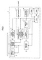
- FIG. 1 is a block diagram showing a general configuration of an optical disk apparatus 1 as an information recording apparatus.
- the optical disk apparatus 1 includes a spindle motor 3 rotating and driving an optical disk 2 as an information recording medium, an optical pickup device 4, a laser control circuit 5, a motor driver 6, a reproduction signal processing circuit 7, a servo controller 8, a buffer RAM 9, a buffer manager 10, an interface 11, a ROM 12, a CPU 13 and a RAM 14. Arrows shown in FIG. 1 show typical flows of signals or information, and do not show all the connection relationship between the respective blocks.
- the optical disk 2 As the optical disk 2, a DVD as a recording-type multilayer optical disk is applied. Specifically, the optical disk 2 is one having two recording layers.
- the optical pickup device 4 includes a semiconductor laser as a light source, an optical system including an objective lens which leads laser light emitted from the semiconductor laser to a recording surface of the optical disk 2, and also, leads reflected light from the optical disk 2 to a predetermined light receiving position, a light receiving device disposed at the light receiving position and receiving the returned light and a driving system (focusing actuator, a tracking actuator, a seek motor and so forth)(not shown). From the light receiving device, an electronic current (electronic current signal) according to a light reception amount is output to the reproduction signal processing circuit 7.
- the servo controller 8 generates a control signal controlling the focusing actuator in the optical pickup device 4 based on a focus error signal, and generates a control signal controlling the tracking actuator in the optical pickup device 4 based on a tracking error signal. These control signals are output to the motor driver 6 from the servo controller 8.
- the motor driver 6 drives the focusing actuator and the tracking actuator in the optical pickup device 4 based on the control signals from the servo controller 8.
- the motor driver 6 controls the spindle motor 3 so that a line velocity of the optical disk 2 may be constant based on instructions from the CPU 13. Further, the motor driver 6 drives the seek motor in the optical pickup device 4 and moves the optical pickup device 4 toward a target track on the optical disk 2 in a radial direction based on instructions from the CPU 13.
- the interface 11 acts as a bi-directional communication interface with a host (for example, a PC 101 as an information processing apparatus shown in FIG. 2) as an external apparatus, and is configured to conform to a standard interface such as an ATAPI, an SCSI or such
- the CPU 11 configures a microcomputer together with the ROM 12 and RAM 14 provided in the optical disk apparatus 1.
- the ROM 12 which also acts as a storage medium, a program which includes a control program described later described in a code recognizable by the CPU 13 is stored.
- the CPU 13 controls operation of the respective parts described above, according to the program stored in the ROM 12, and also, temporarily stores data necessary for the control in the RAM 14.
- the program stored in the ROM 12 is loaded (installed) in a main memory (not shown) of the CPU 13.
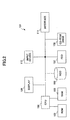
- FIG. 2 is a block diagram showing a general configuration of the PC 101 connected with the optical disk apparatus 1.
- the PC 101 has a configuration such that respective parts are connected with a CPU 104 which configures a microcomputer together with a ROM 102 and a RAM 103 via a bus line 105.
- ROM 102 fixed data is fixedly recorded
- RAM 103 variable data is recorded in a manner of being able to be changed.
- storage devices such as an HDD (hard disk drive), an FDD (flexible disk drive) and a CD-ROM drive 108 are connected via the bus line 105.
- an OS operating system
- various sorts of application programs and so forth are stored, part thereof is copied to the RAM 103 at a time of starting up, and is used by the CPU 104 to control the respective parts.
- a display 109 To the CPU 104, further a display 109, an input device 110 such as a keyboard, mouse and so forth, and an interface 111 are connected via the bus line 105.
- an input device 110 such as a keyboard, mouse and so forth
- an interface 111 By means of the interface 111, connection with an external apparatus is made possible.
- the above-described optical disk apparatus 1 is connected with the PC 101 via the interface 111.
- User data written to the optical disk 2 in the writing processing includes, for example, video data including voice data, picture data and so forth (the same for the other embodiments).
- FIG. 3 is a flow chart showing a flow of the writing processing according to the PTP system in the embodiment of the present invention.
- a method of writing data to the optical disk 2 in the writing processing according to the PTP system is described (see FIG. 12).
- the CPU 13 first carries out processing of writing user data to a first recording layer (in Step S1).
- the user data is written in a data zone (DATA ZONE) in the first recording layer.
- processing of writing of user data to a second recording layer is carried out (S2).
- the user data is written in a data zone (DATA ZONE) of the second recording layer continuous to the user data written to the data zone (DATA ZONE) of the first recording layer.
- the user data is written across between the first recording layer and the second recording layer. Then, after the writing of the user data to the second recording layer is completed, lead-out (LEAD-OUT) data is written to the first recording layer, and lead-in (LEAD-IN) data is written to the second recording layer (S3).
- the lead-out (LEAD-OUT) data is written in a lead-out zone (LEAD-OUT ZONE) in the first recording layer while the lead-in (LEAD-IN) data is written in a lead-in (LEAD-IN) zone in the second recording layer.
- the lead-in (LEAD-IN) data is written in a lead-in zone (LEAD-IN ZONE) in the first recording layer
- the lead-out (LEAD-OUT) data is written in a lead-out zone (LEAD-OUT ZONE) in the second recording layer.
- the lead-out zone in the first recording layer and the lead-in zone in the second recording layer act as around boundary zones, and the lead-out data and lead-in data acts as data indicating switching of the recording layers.
- FIG. 4 is a flow chart showing a flow of writing processing according to the OTP system in the embodiment of the present invention.
- An information recording method for writing data to the optical disk 2 in writing processing according to the OTP system is described (see FIG. 13).
- the CPU 13 first carries out writing of user data to the first recording layer (in Step S11).
- the user data is written in a data zone (DATA ZONE) of the first recording layer.
- user data is written to the second recording layer (S12).
- the user data is written to a data zone (DATA ZONE) of the second recording layer continuous to the user data written to the data zone (DATA ZONE) of the first recording layer.
- the user data is written across between the first recording layer and the second recording layer.
- middle (MIDDLE) data is written to the first recording layer
- middle (MIDDLE) data is written to the second recording layer (S13).
- the middle (MIDDLE) data is written to a middle zone (MIDDLE ZONE) of the first recording layer and to a middle zone (MIDDLE ZONE) of the second recording layer.
- the lead-in (LEAD-IN) data is written in a lead-in zone (LEAD-IN ZONE) of the first recording layer and the lead-out (LEAD-OUT) data is written in a lead-out zone (LEAD-OUT ZONE) of the second recording layer.
- the middle zone in the first recording layer and the middle zone in the second recording layer act as around boundary zones, and the middle data acts as data indicating switching of the recording layers.
- the data other than the user data for example, the lead-in (LEAD-IN) data, the lead-out (LEAD-OUT) data, the middle (MIDDLE) data or such
- the data other than the user data is not written upon switching from the first recording layer to the second recording layer but the user data is continuously written.
- the data is possible to avoid interruption of the processing of writing of the user data to the recording layers.
- control processing is carried out by the CPU 13 of the optical disk apparatus 1 according to the computer program recorded in the ROM 12 of the optical disk apparatus 1 as firmware, for example.
- the ROM 12 acts as storage medium storing therein the computer program.
- a configuration may be made such that, for example, according to the computer program copied to the RAM 103 at a time of starting up from the HDD 106, the CPU 104 in the PC 101 transmits operation instructions to the optical disk apparatus 1, and thereby, the same processing is carried out (the same for the other embodiments).
- the computer program copied to the RAM 103 of the PC 101 may be one stored in the HDD 106 in a form of an application program, or may be one incorporated in the OS.
- the application program is stored in the HDD 106, the application program is distributed in such a manner that it is recorded in a recording medium such as a CD-ROM or such.
- the computer program is read out by means of the FDD 107 or the CD-ROM drive 108 in the PC 101, and then, is stored in the HDD 106. Therefore, in the example mentioned above, the HDD 106, the RAM 103, the FD, the CD-ROM or such acts as a storage medium storing therein the computer program.
- the optical disk apparatus 1 or the PC 101 acts as a computer carrying out the processing according to the flow chart shown in FIG. 3 or FIG. 4 unique to the embodiment.
- a configuration may be provided such that such processing is carried out according to the computer program which is distributed to both the optical disk apparatus 1 and the PC 101.
- the computer program is installed in the PC 101 whereby the optical disk apparatus 1 can carry out processing such as that shown in FIG. 3 or FIG. 4.
- FIGS. 5 through 11 A second embodiment of the present invention is described with reference to FIGS. 5 through 11.
- the same reference numerals are given to parts same as those in the first embodiment, and description thereof is omitted.
- a basic configuration of the present embodiment is approximately same as that in the first embodiment. Difference between the present embodiment and the first embodiment is a flow of writing processing. An information recording method for writing data to the optical disk 2 is described here.
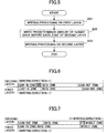
- FIG. 5 is a flow chart showing a flow of writing processing according to the present embodiment
- FIG. 6 roughly illustrates a position to write dummy data according to the PTP system in the present embodiment
- FIG. 7 roughly illustrates a position to write dummy data according to the OTP system in the present embodiment.
- the left hand corresponds to the central side in the optical disk 2 while the right hand corresponds to the peripheral side in the optical disk 2.
- the CPU 13 carries out processing of writing user data to a first recording layer (in Step S21). After that, immediately before a data zone (DATA ZONE) in a second recording layer, a predetermined size of dummy data (corresponding to half-tone-dot filled parts in FIGS. 6 and 7) is written (S22). For example, as shown in FIGS. 6 and 7, the predetermined size of dummy data is written immediately before the data zone (DATA ZONE). After the predetermined size of dummy data is written, processing of writing user data to the second recording layer is carried out (S23). The user data is written across between the first and second recording layers. Then, after writing of the user data to the second recording layer is completed, the CPU 13 carries out Step S3 in the PTP system or carries out Step S13 in FIG. 4 in the OTP system.
- FIG. 8 is a flow chart showing a flow of writing processing in a variant embodiment 1 of the present embodiment
- FIG. 9 roughly shows a position to write dummy data according to the PTP system in the variant embodiment 1
- FIG. 10 roughly shows a position to write dummy data according to the OTP system in the variant embodiment 1.
- the left hand corresponds to the central side in the optical disk 2 while the right hand corresponds to the peripheral side in the optical disk 2.
- the CPU 13 carries out processing of writing user data to a first recording layer (in Step S31). After that, at a top of a data zone (DATA ZONE) in a second recording layer, a predetermined size of dummy data (corresponding to half-tone-dot filled parts in FIGS. 9 and 10) is written (S32). For example, as shown in FIGS. 9 and 10, the predetermined size of dummy data is written at the top of the data zone (DATA ZONE). After the predetermined size of dummy data is written, processing of writing user data to the second recording layer is carried out (S33).
- DATA ZONE data zone
- S33 processing of writing user data to the second recording layer is carried out
- Step S3 a position to start writing of the user data is shifted for the dummy data, and then, the user data is written.
- the user data is written across between the first and second recording layers. Then, after writing of the user data to the second recording layer is completed, the CPU 13 carries out Step S3 in the PTP system or carries out Step S13 in FIG. 4 in the OTP system.
- the dummy data is written immediately before or at the top of the user data to write on the second recording layer.
- the lead-in (LEAD-IN) data in the PTP system or the middle (MIDDLE) data in the OTP system is not yet written, for example, even in a case of carrying out follow-up reproduction of reproducing the user data while writing the same, it is possible to detect the top of the user data written in the second recording layer by reading the dummy data, whereby it is possible to read out the user data written in the second recording layer at predetermined timing.
- FIG. 11 is a flow chart showing a flow of writing processing according to a variant embodiment 2 of the present embodiment.
- the CPU 13 writes a predetermined size of dummy data (see FIGS. 6, 7, 9 and 10) immediately before a data zone (DATA ZONE) of a second recording layer, or at a top of the data zone (DATA ZONE) of the second recording layer (S41).
- the CPU 13 carries out processing of writing user data to the first recording layer (S42), and carries out processing of writing user data to the second recording layer (S43).
- the CPU 13 carries out Step S3 in the PTP system or carries out Step S13 in FIG. 4 in the OTP system.
- Embodiments of the present invention are not limited to those mentioned above and, other various embodiments are contrivable within the scope claimed in the claims below.
Landscapes
- Engineering & Computer Science (AREA)
- Signal Processing (AREA)
- Multimedia (AREA)
- Optical Recording Or Reproduction (AREA)
- Signal Processing For Digital Recording And Reproducing (AREA)
- Management Or Editing Of Information On Record Carriers (AREA)
Abstract
Description
Claims (48)
- A method for writing data to an information recording medium having a plurality of recording layers, comprising:a step of writing user data across between a plurality of the recording layers; anda step of writing data other than the user data in a predetermined zone of the recording layers after writing the user data.
- A method for writing data to an information recording medium having a plurality of recording layers, comprising:a step of writing user data across between a plurality of the recording layers skipping an zone around a boundary of the plurality of recording layers; anda step of writing data which indicates switching of the layers in said zone around the boundary after writing the user data.
- The information recording method as claimed in claim 2, wherein:
said information recording medium comprises an information recording medium to which recording is made according to a parallel track path system;
said zone around the boundary comprises a lead-out zone of a first recording layer in which said user data is written and a lead-in zone of a second recording layer in which said user data is written across from said first recording layer; and
the data indicating switching of the layers comprises lead-out data written in the lead-out zone of the first recording layer and lead-in data written in the lead-in zone of the second recording layer. - The information recording method as claimed in claim 2, wherein:
said information recording medium comprises an information recording medium to which recording is made according to an opposite track path system;
said zone around the boundary comprises a middle zone of a first recording layer in which said user data is written and a middle zone of a second recording layer in which said user data is written across from said first recording layer; and
the data indicating switching of the layers comprises middle data written in the middle zone of the first recording layer and middle data written in the middle zone of the second recording layer. - The information recording method as claimed in claim 1, wherein:
said step of writing the user data comprises a step of, after writing the user data in a predetermined recording layer, writing dummy data immediately before a data zone of a recording layer to which writing is made subsequently. - The information recording method as claimed in claim 2, wherein:
said step of writing the user data comprises a step of, after writing the user data in a predetermined recording layer, writing dummy data immediately before a data zone of a recording layer to which writing is made subsequently. - The information recording method as claimed in claim 1, wherein:
said step of writing the user data comprises a step of, after writing the user data in a predetermined recording layer, writing dummy data at a top of a data zone of a recording layer to which writing is made subsequently. - The information recording method as claimed in claim 2, wherein:
said step of writing the user data comprises a step of, after writing the user data in a predetermined recording layer, writing dummy data at a top of a data zone of a recording layer to which writing is made subsequently. - The information recording method as claimed in claim 1, wherein:
said step of writing the user data comprises a step of, before writing the user data to a plurality of recording layers, writing dummy data immediately before a data zone of a recording layer to which writing is made. - The information recording method as claimed in claim 2, wherein:
said step of writing the user data comprises a step of, before writing the user data to a plurality of recording layers, writing dummy data immediately before a data zone of a recording layer to which writing is made. - The information recording method as claimed in claim 1, wherein:
said step of writing the user data comprises a step of, before writing the user data to a plurality of recording layers, writing dummy data at a top of a data zone of a recording layer to which writing is made. - The information recording method as claimed in claim 2, wherein:
said step of writing the user data comprises a step of, before writing the user data to a plurality of recording layers, writing dummy data at a top of a data zone of a recording layer to which writing is made. - An information recording apparatus for writing data to an information recording medium having a plurality of recording layers, comprising:means for writing user data across between a plurality of the recording layers; andmeans for writing data other than the user data in a predetermined zone of the recording layers after writing the user data.
- An information recording apparatus for writing data to an information recording medium having a plurality of recording layers, comprising:a first writing part writing user data across between a plurality of the recording layers skipping an zone around a boundary of the plurality of recording layers; anda second writing part writing data which indicates switching of the layers in said zone around the boundary after writing the user data.
- The information recording apparatus as claimed in claim 14, wherein:
said information recording medium comprises an information recording medium to which recording is made according to a parallel track path system;
said zone around the boundary comprises a lead-out zone of a first recording layer in which said user data is written and a lead-in zone of a second recording layer in which said user data is written across from said first recording layer; and
the data indicating switching of the layers comprises lead-out data written in the lead-out zone of the first recording layer and lead-in data written in the lead-in zone of the second recording layer. - The information recording apparatus as claimed in claim 14, wherein:
said information recording medium comprises an information recording medium to which recording is made according to an opposite track path system;
said zone around the boundary comprises a middle zone of a first recording layer in which said user data is written and a middle zone of a second recording layer in which said user data is written across from said first recording layer; and
the data indicating switching of the layers comprises middle data written in the middle zone of the first recording layer and middle data written in the middle zone of the second recording layer. - The information recording apparatus as claimed in claim 13, wherein:
after writing the user data in a predetermined recording layer, said first writing part writes dummy data immediately before a data zone of a recording layer to which writing is made subsequently. - The information recording apparatus as claimed in claim 14, wherein:
after writing the user data in a predetermined recording layer, said first writing part writes dummy data immediately before a data zone of a recording layer to which writing is made subsequently. - The information recording apparatus as claimed in claim 13, wherein:
after writing the user data in a predetermined recording layer, said first writing part writes dummy data at a top of a data zone of a recording layer to which writing is made subsequently. - The information recording apparatus as claimed in claim 14, wherein:
after writing the user data in a predetermined recording layer, said first writing part writes dummy data at a top of a data zone of a recording layer to which writing is made subsequently. - The information recording apparatus as claimed in claim 13, wherein:
before writing the user data to a plurality of recording layers, said first writing part writes dummy data immediately before a data zone of a recording layer to which writing is made. - The information recording apparatus as claimed in claim 14, wherein:
before writing the user data to a plurality of recording layers, said first writing part writes dummy data immediately before a data zone of a recording layer to which writing is made. - The information recording apparatus as claimed in claim 13, wherein:
before writing the user data to a plurality of recording layers, said first writing part writes dummy data at a top of a data zone of a recording layer to which writing is made. - The information recording apparatus as claimed in claim 14, wherein:
before writing the user data to a plurality of recording layers, said first writing part writes dummy data at a top of a data zone of a recording layer to which writing is made. - A program, installed in a computer provided in an information recording apparatus for writing data to an information recording medium having a plurality of recording layers, comprising instructions for causing the computer to carry out:a first step of writing user data across between a plurality of the recording layers; anda second step of writing data other than the user data in a predetermined zone of the recording layers after writing the user data.
- A program, installed in a computer provided in an information recording apparatus for writing data to an information recording medium having a plurality of recording layers, comprising instructions for causing the computer to carry out:a first step of writing user data across between a plurality of the recording layers skipping an zone around a boundary of the plurality of recording layer; anda second step of writing data which indicates switching of the layers in said zone around the boundary after writing the user data.
- The program as claimed in claim 26, wherein:
said information recording medium comprises an information recording medium to which recording is made according to a parallel track path system;
said zone around the boundary comprises a lead-out zone of a first recording layer in which said user data is written and a lead-in zone of a second recording layer in which said user data is written across from said first recording layer; and
the data indicating switching of the layers comprises lead-out data written in the lead-out zone of the first recording layer and lead-in data written in the lead-in zone of the second recording layer. - The program as claimed in claim 26, wherein:
said information recording medium comprises an information recording medium to which recording is made according to an opposite track path system;
said zone around the boundary comprises a middle zone of a first recording layer in which said user data is written and a middle zone of a second recording layer in which said user data is written across from said first recording layer; and
the data indicating switching of layers comprises middle data written in the middle zone of the first recording layer and middle data written in the middle zone of the second recording layer. - The program as claimed in claim 25, wherein:
said first step comprises a step of, after writing the user data in a predetermined recording layer, writing dummy data immediately before a data zone of a recording layer to which writing is made subsequently. - The program as claimed in claim 26, wherein:
said first step comprises a step of, after writing the user data in a predetermined recording layer, writing dummy data immediately before a data zone of a recording layer to which writing is made subsequently. - The program as claimed in claim 25, wherein:
said first step comprises a step of, after writing the user data in a predetermined recording layer, writing dummy data at a top of a data zone of a recording layer to which writing is made subsequently. - The program as claimed in claim 26, wherein:
said first step comprises a step of, after writing the user data in a predetermined recording layer, writing dummy data at a top of a data zone of a recording layer to which writing is made subsequently. - The program as claimed in claim 25, wherein:
said first step comprises a step of, before writing the user data to a plurality of recording layers, writing dummy data immediately before a data zone of a recording layer to which writing is made. - The program as claimed in claim 26, wherein:
said first step comprises a step of, before writing the user data to a plurality of recording layers, writing dummy data immediately before a data zone of a recording layer to which writing is made. - The program as claimed in claim 25, wherein:
said first step comprises a step of, before writing the user data to a plurality of recording layers, writing dummy data at a top of a data zone of a recording layer to which writing is made. - The program as claimed in claim 26, wherein:
said first step comprises a step of, before writing the user data to a plurality of recording layers, writing dummy data at a top of a data zone of a recording layer to which writing is made. - A computer readable storage medium in which the program claimed in claim 25 is stored.
- A computer readable storage medium in which the program claimed in claim 26 is stored.
- A computer readable storage medium in which the program claimed in claim 27 is stored.
- A computer readable storage medium in which the program claimed in claim 28 is stored.
- A computer readable storage medium in which the program claimed in claim 29 is stored.
- A computer readable storage medium in which the program claimed in claim 30 is stored.
- A computer readable storage medium in which the program claimed in claim 31 is stored.
- A computer readable storage medium in which the program claimed in claim 32 is stored.
- A computer readable storage medium in which the program claimed in claim 33 is stored.
- A computer readable storage medium in which the program claimed in claim 34 is stored.
- A computer readable storage medium in which the program claimed in claim 35 is stored.
- A computer readable storage medium in which the program claimed in claim 36 is stored.
Applications Claiming Priority (5)
| Application Number | Priority Date | Filing Date | Title |
|---|---|---|---|
| JP2003083930 | 2003-03-25 | ||
| JP2003083930 | 2003-03-25 | ||
| JP2004013260 | 2004-01-21 | ||
| JP2004013260A JP3584033B1 (en) | 2003-03-25 | 2004-01-21 | Information recording method, information recording device, program and storage medium |
| PCT/JP2004/003083 WO2004086394A1 (en) | 2003-03-25 | 2004-03-10 | Information recording method, information recording device, program, and computer-readable information storage medium |
Publications (3)
| Publication Number | Publication Date |
|---|---|
| EP1607967A1 true EP1607967A1 (en) | 2005-12-21 |
| EP1607967A4 EP1607967A4 (en) | 2011-02-16 |
| EP1607967B1 EP1607967B1 (en) | 2015-05-06 |
Family
ID=33100381
Family Applications (1)
| Application Number | Title | Priority Date | Filing Date |
|---|---|---|---|
| EP20040719072 Expired - Lifetime EP1607967B1 (en) | 2003-03-25 | 2004-03-10 | Information recording method, information recording apparatus and program for writing data to a multilayer recording medium |
Country Status (7)
| Country | Link |
|---|---|
| US (2) | US7177256B2 (en) |
| EP (1) | EP1607967B1 (en) |
| JP (1) | JP3584033B1 (en) |
| CN (1) | CN1751351B (en) |
| ES (1) | ES2543085T3 (en) |
| TW (1) | TWI285882B (en) |
| WO (1) | WO2004086394A1 (en) |
Cited By (3)
| Publication number | Priority date | Publication date | Assignee | Title |
|---|---|---|---|---|
| EP1522995A3 (en) * | 2003-08-18 | 2006-06-07 | Sony Corporation | Recording apparatus and recording method |
| EP1676266A2 (en) * | 2003-10-13 | 2006-07-05 | Koninklijke Philips Electronics N.V. | Method and recording apparatus for recording information on a multi-layer disc |
| EP1803119A4 (en) * | 2004-10-23 | 2009-01-21 | Samsung Electronics Co Ltd | INFORMATION STORAGE MEDIUM, READING / WRITING APPARATUS, AND READING / WRITING METHOD |
Families Citing this family (17)
| Publication number | Priority date | Publication date | Assignee | Title |
|---|---|---|---|---|
| EP1154691A4 (en) * | 1999-01-05 | 2004-07-07 | Massachusetts Eye & Ear Infirm | Targeted transscleral controlled release drug delivery to the retina and choroid |
| WO2003092665A2 (en) * | 2002-05-02 | 2003-11-13 | Massachusetts Eye And Ear Infirmary | Ocular drug delivery systems and use thereof |
| JP2004310997A (en) | 2003-03-24 | 2004-11-04 | Ricoh Co Ltd | Optical information recording medium, optical information recorder, information processor, program and information recording method |
| JP3734816B2 (en) * | 2003-03-25 | 2006-01-11 | 株式会社リコー | Optical information recording apparatus, optical information recording medium, optical information recording method, program, and storage medium |
| JP3954556B2 (en) * | 2003-03-25 | 2007-08-08 | 株式会社リコー | Information recording apparatus, information recording method, information recording program, and storage medium for storing information recording program |
| JP2004310972A (en) | 2003-03-25 | 2004-11-04 | Ricoh Co Ltd | Information processing device, information recording device, information processing system, information recording method, information recording program, and storage medium |
| JP2004295950A (en) | 2003-03-25 | 2004-10-21 | Ricoh Co Ltd | Optical information recording medium, optical information recording device, information processing device, optical information recording method, program, and storage medium |
| JP3594243B1 (en) | 2003-03-25 | 2004-11-24 | 株式会社リコー | Optical information recording method, optical information recording device, information processing device, optical information recording medium |
| JP4633346B2 (en) | 2003-05-12 | 2011-02-16 | ソニー株式会社 | Recording medium, recording apparatus, and recording method |
| WO2005034118A2 (en) * | 2003-10-06 | 2005-04-14 | Koninklijke Philips Electronics N.V. | Method, system, playback device and recorder for duplicating multi layer record carriers |
| KR100677114B1 (en) * | 2004-04-27 | 2007-02-02 | 삼성전자주식회사 | Information storage medium, method and apparatus for recording / reproducing data of the information storage medium |
| JP4197170B2 (en) * | 2004-05-17 | 2008-12-17 | 株式会社リコー | Recording method, information recording apparatus, program, and recording medium |
| KR100895633B1 (en) | 2004-10-04 | 2009-05-07 | 파이오니아 가부시키가이샤 | Information recording device and method, and a recording medium recording thereon a computer program |
| JP4254688B2 (en) * | 2004-10-29 | 2009-04-15 | ティアック株式会社 | Optical disc apparatus and data recording apparatus therefor |
| JP2006294101A (en) * | 2005-04-07 | 2006-10-26 | Ricoh Co Ltd | Information recording / reproducing device |
| KR101304571B1 (en) * | 2006-02-24 | 2013-09-05 | 삼성전자주식회사 | Apparatus and method for playing optical disc |
| JP2007299447A (en) * | 2006-04-28 | 2007-11-15 | Teac Corp | Optical disc apparatus, data recording method, and multilayer optical disc medium |
Family Cites Families (24)
| Publication number | Priority date | Publication date | Assignee | Title |
|---|---|---|---|---|
| AU3914895A (en) * | 1994-11-30 | 1996-06-06 | Sony Corporation | Data recording medium and record/playback apparatus using the data recording medium |
| JPH08212561A (en) * | 1994-11-30 | 1996-08-20 | Sony Corp | Data recording medium and recording / reproducing apparatus using the data recording medium |
| JP2871534B2 (en) * | 1995-06-26 | 1999-03-17 | 株式会社日立製作所 | Digital signal recording method, disk reproducing apparatus, and disk reproducing method |
| US5703867A (en) * | 1995-07-21 | 1997-12-30 | Hitachi, Ltd. | Optical recording medium having a dummy area at leading and/or trailing positions of recording area |
| CN1115045C (en) * | 1995-09-29 | 2003-07-16 | 松下电器产业株式会社 | Method and device for bit stream interleaved recording and playback of media |
| WO1997015050A1 (en) * | 1995-10-19 | 1997-04-24 | Matsushita Electric Industrial Co., Ltd. | Information storage medium, information reproducing method, and information reproducing apparatus |
| DE69703790T2 (en) * | 1996-02-08 | 2001-08-09 | Matsushita Electric Industrial Co., Ltd. | OPTICAL DISK, OPTICAL DISK DEVICE AND METHOD FOR PLAYING BACK INFORMATION ON AN OPTICAL DISK |
| JP3707137B2 (en) * | 1996-07-04 | 2005-10-19 | ソニー株式会社 | Recording medium and playback device |
| JP3837889B2 (en) * | 1997-12-29 | 2006-10-25 | ソニー株式会社 | Encoding method and encoding apparatus |
| JP2000048542A (en) | 1998-07-31 | 2000-02-18 | Nippon Columbia Co Ltd | Data preparation method for multilayer disk |
| US6917579B2 (en) * | 1999-03-23 | 2005-07-12 | Flexplay Technologies, Inc. | Limited play optical devices with interstitial reactive layer and methods of making same |
| JP4103061B2 (en) * | 1999-03-31 | 2008-06-18 | ソニー株式会社 | Recording management data generation method, data recording method, and apparatus thereof |
| WO2000067257A2 (en) * | 1999-04-28 | 2000-11-09 | Matsushita Electric Industrial Co., Ltd. | Optical disk, optical disk recording and reproducing apparatus, method for recording, reproducing and deleting data on optical disk, and information processing system |
| JP2001126255A (en) * | 1999-10-22 | 2001-05-11 | Sony Corp | Optical recording method and optical recording device |
| DE60113346T2 (en) * | 2000-07-26 | 2006-06-22 | Kabushiki Kaisha Toshiba, Kawasaki | Record carrier for information with an index start field |
| US6845071B2 (en) * | 2001-03-28 | 2005-01-18 | Matsushita Electric Industrial Co., Ltd. | Optical disc apparatus and recording power determining method thereof |
| JP2003016648A (en) * | 2001-06-28 | 2003-01-17 | Toshiba Corp | Method for recording information on information medium having multilayer recording layer and device using the method |
| JP2003223763A (en) * | 2001-11-20 | 2003-08-08 | Ricoh Co Ltd | Information recording / reproducing device, information recording / reproducing unit, information recording / reproducing method, program and storage medium |
| JP2003168221A (en) * | 2001-11-28 | 2003-06-13 | Tdk Corp | Multilayer optical recording medium, recording method of recording data, and recording device |
| EP1324148A1 (en) * | 2001-12-28 | 2003-07-02 | Ricoh Company, Ltd. | Driving device and image forming apparatus including the same |
| US7974520B2 (en) * | 2002-04-26 | 2011-07-05 | Ricoh Company, Ltd. | Information recording ensuring compatibility with different types of recording media |
| JP2004253109A (en) * | 2003-01-27 | 2004-09-09 | Ricoh Co Ltd | Information recording / reproducing apparatus, program, computer-readable recording medium, and defective area management method |
| JP2004265567A (en) * | 2003-02-14 | 2004-09-24 | Ricoh Co Ltd | Information recording / reproducing device, disk device, program, computer-readable recording medium, and defective area replacement method |
| JP2004310972A (en) * | 2003-03-25 | 2004-11-04 | Ricoh Co Ltd | Information processing device, information recording device, information processing system, information recording method, information recording program, and storage medium |
-
2004
- 2004-01-21 JP JP2004013260A patent/JP3584033B1/en not_active Expired - Fee Related
- 2004-03-10 CN CN200480004507.9A patent/CN1751351B/en not_active Expired - Fee Related
- 2004-03-10 ES ES04719072.3T patent/ES2543085T3/en not_active Expired - Lifetime
- 2004-03-10 WO PCT/JP2004/003083 patent/WO2004086394A1/en not_active Ceased
- 2004-03-10 EP EP20040719072 patent/EP1607967B1/en not_active Expired - Lifetime
- 2004-03-18 TW TW093107329A patent/TWI285882B/en not_active IP Right Cessation
- 2004-09-23 US US10/947,279 patent/US7177256B2/en not_active Expired - Lifetime
-
2006
- 2006-12-18 US US11/640,213 patent/US7573799B2/en not_active Expired - Lifetime
Non-Patent Citations (2)
| Title |
|---|
| No further relevant documents disclosed * |
| See also references of WO2004086394A1 * |
Cited By (7)
| Publication number | Priority date | Publication date | Assignee | Title |
|---|---|---|---|---|
| EP1522995A3 (en) * | 2003-08-18 | 2006-06-07 | Sony Corporation | Recording apparatus and recording method |
| US7539114B2 (en) | 2003-08-18 | 2009-05-26 | Sony Corporation | Recording apparatus and recording method |
| EP1676266A2 (en) * | 2003-10-13 | 2006-07-05 | Koninklijke Philips Electronics N.V. | Method and recording apparatus for recording information on a multi-layer disc |
| EP1803119A4 (en) * | 2004-10-23 | 2009-01-21 | Samsung Electronics Co Ltd | INFORMATION STORAGE MEDIUM, READING / WRITING APPARATUS, AND READING / WRITING METHOD |
| US7974175B2 (en) | 2004-10-23 | 2011-07-05 | Samsung Electronics Co., Ltd. | Information storage medium, and recording/reproducing apparatus and recording/reproducing method |
| US8199630B2 (en) | 2004-10-23 | 2012-06-12 | Samsung Electronics Co., Ltd. | Information storage medium, and recording/reproducing apparatus and recording/reproducing method |
| US8208355B2 (en) | 2004-10-23 | 2012-06-26 | Samsung Electronics Co., Ltd. | Information storage medium, and recording/reproducing apparatus and recording/reproducing method |
Also Published As
| Publication number | Publication date |
|---|---|
| CN1751351A (en) | 2006-03-22 |
| WO2004086394A1 (en) | 2004-10-07 |
| US20070097807A1 (en) | 2007-05-03 |
| JP2004310996A (en) | 2004-11-04 |
| US7177256B2 (en) | 2007-02-13 |
| US20050044309A1 (en) | 2005-02-24 |
| TWI285882B (en) | 2007-08-21 |
| ES2543085T3 (en) | 2015-08-14 |
| US7573799B2 (en) | 2009-08-11 |
| CN1751351B (en) | 2011-06-15 |
| EP1607967B1 (en) | 2015-05-06 |
| JP3584033B1 (en) | 2004-11-04 |
| TW200425078A (en) | 2004-11-16 |
| EP1607967A4 (en) | 2011-02-16 |
Similar Documents
| Publication | Publication Date | Title |
|---|---|---|
| EP1607967B1 (en) | Information recording method, information recording apparatus and program for writing data to a multilayer recording medium | |
| US8000201B2 (en) | Information recording system with information recording and reproducing apparatus having a data recorder | |
| US7385897B2 (en) | Information recording device, information recording method, information recording program, and recording medium | |
| JP2004288308A (en) | Information recording method and apparatus | |
| JP4183553B2 (en) | Recording method, program, recording medium, and information recording apparatus | |
| KR20020042747A (en) | Dvd-rom backwards compatible defective sector management in recordable dvd media | |
| JP4083651B2 (en) | Information recording method and information recording apparatus | |
| JP4174235B2 (en) | Information recording method, information recording apparatus, and information recording / reproducing system | |
| US7843779B2 (en) | Recording method, information recording medium, reproducing method, information recording device, and information reproducing device | |
| CN100421169C (en) | Information recording device, information recording method | |
| JP2004288362A (en) | Information recording method, information recording device, information recording program, and storage medium | |
| JP2003173626A (en) | Information recording / reproducing device | |
| JP4343936B2 (en) | Information recording method, information recording apparatus, information recording program, and recording medium | |
| JP2004303421A (en) | Information recording method and apparatus | |
| JP4343971B2 (en) | Information recording method | |
| JP2004241006A (en) | Backup disk creation method, program and recording medium, and information recording system | |
| JP2008217987A (en) | Recording method, program, recording medium, information recording apparatus, and information recording system | |
| JP2007048454A (en) | Information recording system | |
| JP2004103169A (en) | Recording method, program, recording medium, and information recording device | |
| JP2002230777A (en) | Disk recorder |
Legal Events
| Date | Code | Title | Description |
|---|---|---|---|
| PUAI | Public reference made under article 153(3) epc to a published international application that has entered the european phase |
Free format text: ORIGINAL CODE: 0009012 |
|
| 17P | Request for examination filed |
Effective date: 20050808 |
|
| AK | Designated contracting states |
Kind code of ref document: A1 Designated state(s): AT BE BG CH CY CZ DE DK EE ES FI FR GB GR HU IE IT LI LU MC NL PL PT RO SE SI SK TR |
|
| AX | Request for extension of the european patent |
Extension state: AL LT LV MK |
|
| DAX | Request for extension of the european patent (deleted) | ||
| RBV | Designated contracting states (corrected) |
Designated state(s): DE ES FR GB IT NL |
|
| A4 | Supplementary search report drawn up and despatched |
Effective date: 20110118 |
|
| RIC1 | Information provided on ipc code assigned before grant |
Ipc: G11B 20/12 20060101ALI20110112BHEP Ipc: G11B 27/30 20060101AFI20110112BHEP Ipc: G11B 7/0045 20060101ALI20110112BHEP Ipc: G11B 27/034 20060101ALI20110112BHEP Ipc: G11B 7/007 20060101ALI20110112BHEP |
|
| 17Q | First examination report despatched |
Effective date: 20110408 |
|
| GRAP | Despatch of communication of intention to grant a patent |
Free format text: ORIGINAL CODE: EPIDOSNIGR1 |
|
| INTG | Intention to grant announced |
Effective date: 20140822 |
|
| GRAS | Grant fee paid |
Free format text: ORIGINAL CODE: EPIDOSNIGR3 |
|
| GRAA | (expected) grant |
Free format text: ORIGINAL CODE: 0009210 |
|
| AK | Designated contracting states |
Kind code of ref document: B1 Designated state(s): DE ES FR GB IT NL |
|
| REG | Reference to a national code |
Ref country code: GB Ref legal event code: FG4D |
|
| REG | Reference to a national code |
Ref country code: DE Ref legal event code: R096 Ref document number: 602004047131 Country of ref document: DE Effective date: 20150618 |
|
| REG | Reference to a national code |
Ref country code: NL Ref legal event code: T3 |
|
| REG | Reference to a national code |
Ref country code: ES Ref legal event code: FG2A Ref document number: 2543085 Country of ref document: ES Kind code of ref document: T3 Effective date: 20150814 |
|
| REG | Reference to a national code |
Ref country code: DE Ref legal event code: R097 Ref document number: 602004047131 Country of ref document: DE |
|
| PLBE | No opposition filed within time limit |
Free format text: ORIGINAL CODE: 0009261 |
|
| STAA | Information on the status of an ep patent application or granted ep patent |
Free format text: STATUS: NO OPPOSITION FILED WITHIN TIME LIMIT |
|
| REG | Reference to a national code |
Ref country code: FR Ref legal event code: PLFP Year of fee payment: 13 |
|
| 26N | No opposition filed |
Effective date: 20160209 |
|
| REG | Reference to a national code |
Ref country code: FR Ref legal event code: PLFP Year of fee payment: 14 |
|
| REG | Reference to a national code |
Ref country code: FR Ref legal event code: PLFP Year of fee payment: 15 |
|
| PGFP | Annual fee paid to national office [announced via postgrant information from national office to epo] |
Ref country code: NL Payment date: 20200319 Year of fee payment: 17 Ref country code: GB Payment date: 20200323 Year of fee payment: 17 Ref country code: DE Payment date: 20200320 Year of fee payment: 17 |
|
| PGFP | Annual fee paid to national office [announced via postgrant information from national office to epo] |
Ref country code: FR Payment date: 20200319 Year of fee payment: 17 |
|
| PGFP | Annual fee paid to national office [announced via postgrant information from national office to epo] |
Ref country code: ES Payment date: 20200522 Year of fee payment: 17 |
|
| PGFP | Annual fee paid to national office [announced via postgrant information from national office to epo] |
Ref country code: IT Payment date: 20200318 Year of fee payment: 17 |
|
| REG | Reference to a national code |
Ref country code: DE Ref legal event code: R119 Ref document number: 602004047131 Country of ref document: DE |
|
| REG | Reference to a national code |
Ref country code: NL Ref legal event code: MM Effective date: 20210401 |
|
| GBPC | Gb: european patent ceased through non-payment of renewal fee |
Effective date: 20210310 |
|
| PG25 | Lapsed in a contracting state [announced via postgrant information from national office to epo] |
Ref country code: NL Free format text: LAPSE BECAUSE OF NON-PAYMENT OF DUE FEES Effective date: 20210401 Ref country code: FR Free format text: LAPSE BECAUSE OF NON-PAYMENT OF DUE FEES Effective date: 20210331 Ref country code: GB Free format text: LAPSE BECAUSE OF NON-PAYMENT OF DUE FEES Effective date: 20210310 Ref country code: DE Free format text: LAPSE BECAUSE OF NON-PAYMENT OF DUE FEES Effective date: 20211001 |
|
| PG25 | Lapsed in a contracting state [announced via postgrant information from national office to epo] |
Ref country code: IT Free format text: LAPSE BECAUSE OF NON-PAYMENT OF DUE FEES Effective date: 20210310 |
|
| REG | Reference to a national code |
Ref country code: ES Ref legal event code: FD2A Effective date: 20220523 |
|
| PG25 | Lapsed in a contracting state [announced via postgrant information from national office to epo] |
Ref country code: ES Free format text: LAPSE BECAUSE OF NON-PAYMENT OF DUE FEES Effective date: 20210311 |