EP1607683B1 - Klappbarer Campingkocher - Google Patents
Klappbarer Campingkocher Download PDFInfo
- Publication number
- EP1607683B1 EP1607683B1 EP05252982A EP05252982A EP1607683B1 EP 1607683 B1 EP1607683 B1 EP 1607683B1 EP 05252982 A EP05252982 A EP 05252982A EP 05252982 A EP05252982 A EP 05252982A EP 1607683 B1 EP1607683 B1 EP 1607683B1
- Authority
- EP
- European Patent Office
- Prior art keywords
- fuel
- stove
- clamshells
- folding
- clamshell
- Prior art date
- Legal status (The legal status is an assumption and is not a legal conclusion. Google has not performed a legal analysis and makes no representation as to the accuracy of the status listed.)
- Expired - Lifetime
Links
Images



Classifications
-
- F—MECHANICAL ENGINEERING; LIGHTING; HEATING; WEAPONS; BLASTING
- F24—HEATING; RANGES; VENTILATING
- F24C—DOMESTIC STOVES OR RANGES ; DETAILS OF DOMESTIC STOVES OR RANGES, OF GENERAL APPLICATION
- F24C3/00—Stoves or ranges for gaseous fuels
- F24C3/14—Stoves or ranges for gaseous fuels with special adaptation for travelling, e.g. collapsible
Definitions
- the present invention relates to stoves, and more specifically to portable stoves.
- Portable stoves are popular cooking appliances, especially for use while camping or picnicking.
- Portable stoves commonly are powered by combustible gasses, such as propane gas.
- a typical portable stove includes a stove frame, one or more burner assemblies arranged in the frame, and a gas supply, such as a gas canister, coupled to the burner assembly via a control valve.
- Smaller versions convenient for backpacking may be not much larger than the gas canister itself, while larger versions designed for group camping may be the size of a large briefcase.
- suitcase-style portable stoves work well for their intended purpose, there are some limitations to their use. Generally, the suitcase-style portable stoves require a separate table on which to rest, and must be level or near level on that table. In addition, although the suitcase-style portable stoves fold into a box configuration, they are still somewhat bulky for travel and storage. Care must be taken with the devices because there are often objects that extend outside the box configuration, such as gas line attachments or control knobs, which may need protection during storage and/or transport.
- US-A-3 789 821 shows a portable camping stove, having two burners, housed in separate casings wherein the casings are hinged together so that the burners fold face-to-face and the folded housing takes on the appearance of a briefcase
- US-A-2 860 224 shows a portable utility device which has increased adaptability in folding different parts together, in a foldable device.
- US-A-5 954 044 shows a connector for securing a conduit to a fuel source, wherein the source includes a non circular, cylindrical pedestal having a fluid source outlet extending there through and an annular groove surrounding the pedestal.
- the invention is characterized by the features of claim 1.
- the following presents a simplified summary in order to provide a basic understanding of the invention.
- a folding camping stove is provided.
- the folding camping stove is formed in a clamshell configuration, having two clamshells that fold outward to expose at least two cooking surfaces.
- Pivot points are provided on the folding camping stove. Fuel trains for the two clamshells are positioned at the pivot points.
- a regulator and manifold assembly may be provided for providing gas from a canister to the folding stove.
- the manifold splits the gas coming from the regulator and directs it to opposite sides of the folding stove.
- the manifold may direct fuel to two fuel trains, one each positioned at the two pivot points.
- Each fuel train may include a fuel conduit that extends the width of the stove and about which the respective clamshell rotates.
- the separate fuel trains and the manifold and regulator assembly may provide a single regulator system that is capable of providing fuel to two opposite sides of the folding stove.
- the separate fuel trains permit the folding stove to be configured without having a fuel line crossing either pivot location, which permits the folding stove to be manufactured without the need for a flexible fuel line extending through the two pivot points.
- the clamshells pivot along their fuel trains, and the couplings attach at the pivot points.
- the folding stove is narrower at a central portion of the stove at which the fuel trains are located.
- the body of the clamshells extends outward beyond the central portion, and control knobs or any other features extending from this central section are protected by the remainder of the clamshells extending beyond these features.
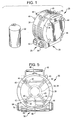
- FIG. 1 is a side perspective view of a folding stove in accordance with an embodiment of the invention
- FIG. 2 is a side perspective view of the folding stove of FIG. 1 , folded outward into an open configuration
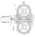
- FIG. 3 is a top view of the folding stove of FIG. 2 ;
- FIG. 4 is a side perspective view of the folding stove of FIG. 1 , with the stove opened more than 180 degrees;
- FIG. 5 is a side view of the folding stove of FIG. 1 ;
- FIG. 6 is a cross-sectional view taken along the section lines 6--6 of FIG. 3 ;
- FIG. 7 is a cross-sectional view taken along the section lines 7--7 of FIG. 3 ;
- FIG. 8 is a side perspective view of an alternate embodiment of a folding stove in accordance with the present invention.
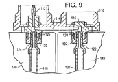
- FIG. 9 is an alternate example of a fuel train system for the folding stove of FIG. 1 , which does not form part of the invention.
- FIG. 1 shows a folding stove 20 in accordance with an embodiment of the invention.
- the folding stove 20 is designed for use with combustible gasses, such as propane gas, and may be provided fuel by, for example, a gas canister 22.
- the folding stove 20 includes two clamshells 24, 26.
- the two clamshells 24, 26 are folded together in a storage configuration.
- the two clamshells 24, 26 may be rotated outward about two pivot points, in the embodiment shown, two fuel trains 28, 30, so that the folding stove 20 is in an opened configuration.
- burner eyes 32, 34, one each in the two clamshells 24, 26, are exposed as cooking surfaces.
- fuel trains we mean the conduit system through which fuel flows to the burner eyes 32, 34.
- the numbers 28 and 30 e.g., FIG. 2 ) in the drawings point generally to the area where these are located in the shown embodiment.
- each of the burner eyes 32, 34 includes a cooking grate 36, 38 mounted around and partly over the respective burner eye 32, 34.
- cooking grates such as the cooking grates 36, 38, provide a platform on which a pot or other cooking vessel may be placed when heated by the respective burner eye 32, 34.
- the platform is provided by a series of prongs 40, 42.
- each prong 40 on the clamshell 24 is offset slightly relative to the counterpart prong 42 on the other clamshell 26. That is, each prong 40 is positioned so that when the folding stove 20 is folded into the compact configuration in FIG. 1 , the prong does not engage the prong 42 on the opposite clamshell, but instead extends adjacent to the prong 42, and thus is slightly offset relative to the other prong.
- the slight offset may be, for example, one quarter of an inch or another sufficient amount to provide nesting of the two cooking grates 36, 38, when the clamshells 24, 26 are folded to the compact configuration shown in FIG. 1 .
- the slight offset of the prongs 40, 42 can be seen from the top view in FIG. 3 , and the nesting of the prongs 40, 42 can be seen in phantom in FIG. 5 .
- This nesting effect provides more compact storage of the folding stove 20, yet, by not providing a significant offset, a symmetrical appearance is maintained for the cooking grates 36, 38, as can be seen in FIG. 3 .
- the folding stove 20 includes feet 44 on the rearward surfaces of the clamshells 24, 26.
- handles such as handles 46
- the handles 46 are positioned so that they are hinged from a top portion of the folding stove 20 when the folding stove is in the compact configuration of FIG. 1 .
- a latch such as a latch 48, may be provided for temporarily locking the folding stove 20 in the compact configuration.
- a regulator and manifold assembly 50 is provided for supplying gas from a canister, such as the gas canister 22, to the two fuel trains 28, 30.
- the regulator and manifold assembly 50 includes a regulator 51.
- Regulators are known in the burning appliances art and in general are designed to drop the fuel pressure from the high pressure of a fuel canister, such as the gas canister 22, to an operating pressure for a stove or another gas-operated appliance.
- the regulator 51 is connected to a manifold 52.
- the manifold 52 splits the low pressure fuel stream exiting the regulator 51 into two conduits 54, 56. These two conduits 54, 56 each include a coupling 55, 57, for attaching onto appropriate structures (described below) at the ends of the fuel trains 28, 30.
- the regulator and manifold assembly 50 is shown attached in this manner in FIG. 3 .
- the two conduits 54, 56, when attached about the couplings 55, 57, are in fluid communication with internal fuel conduits 58, 60 that extend along the fuel trains 28, 30.
- the internal fuel conduits 58, 60 in an embodiment are straight pipes that extend co-axially with a rotational axis for each of the clamshells 24, 26.
- the couplings 55, 57 are attached to the fuel trains 28, 30 in a manner such that the fuel trains 28, 30 may freely rotate relative to the couplings without gas loss.
- Such couplings are known in the art, and may be provided, for example by quick release couplings, such as are disclosed in United States patent number 2,784,987 , although many different couplings may be used.
- Control knobs 62, 64 are mounted on the ends of the internal fuel conduits 58, 60 opposite the attachment of the couplings 55, 57.
- the control knobs 62, 64 are accessible from the outside of the folding stove 20.
- the control knobs 62, 64 include valves (described below) that open and close and regulate a flow of fuel provided from the internal fuel conduits 58, 60, and into gas flow lines 66, 68 which lead to the burner eyes 32, 34, respectively.
- the internal fuel conduits 58, 60 attach to probes 72, 74, which are configured for attachment to the couplings 55 of the regulator and manifold assembly 50.
- the probes 72, 74 are fitted within openings of the outer walls of the clamshells 24, 26, and are permitted to float freely therein. Allowing the probes to float freely permits longitudinal displacement of the fuel conduits 58, 60, allowing for manufacturing tolerances and/or expansion of the metal.
- a linkage in the embodiment shown, a linkage 90 is provided for spacing the two fuel trains 28, 30, and permitting free rotation of these fuel trains 28, 30 relative to one another.
- the linkage 90 receives the rear portion of the probes 72, 74, and is mounted for free rotation on surfaces 82, 84 of the probes 72, 74.
- the surfaces 82, 84 may be defined, for example, between the shoulders 76, 78 on the probes 72, 74 and a pair of lock nuts 86, 88.
- other structures may be provided that allow free rotation of the linkage 90 relative to the fuel trains 28, 30.
- the linkage 90 is rotatably mounted to the probes 72, 74, but the linkage may be attached at other locations to the fuel train. In addition to free rotation, the linkage 90 also maintains a constant spacing of the fuel trains 28, 30.
- the linkage 90 in one embodiment includes holes for receiving the probes 72, 74, so that the probes and the fuel trains 28, 30 may be rotated relative to the linkage but may not be moved outward or inward relative to one another.
- Another linkage 80 may be provided at the opposite end for similarly spacing and allowing free rotation of the fuel trains 28, 30. If desired, the internal fuel conduits 58, 60 may be attached in a different manner at the opposite end, such as by anchoring the end to the internal fuel conduits 58, 60, because free flotation is not needed at both ends.
- the linkage 80 may be configured and arranged to recess a portion of the control knobs 62, 64.
- the internal fuel conduit 58 may attach to a valve body 91, which in turn is anchored to the casing for the clamshell 24 by a jam nut 92.
- a valve stem 93 is positioned in the valve body 91 and is held in position by a stem nut 94.
- the control knob 62 rotates to move the valve stem 93 and open flow of fuel between the internal fuel conduit 58 and the gas flow line 66.
- the linkage 80 is positioned between a shoulder 95 on the valve body 91 and the stem nut 94, and is free to rotate relative to the valve body in much the same manner that the other linkage 90 is free to rotate.
- the linkages 80, 90 permit free rotation of the fuel trains 28, 30 along with the associated clamshells 24, 26.
- the associated fuel train 28 and its internal fuel conduit 58 and gas flow line 66 all rotate with, and are fixed for movement with, the clamshell 24.
- no flexible lines or other structures to accommodate bending are required for the fuel train 28, reducing costs and simplifying routing of the fuel through the clamshell 24.
- connection of the regulator and manifold assembly 50 via the coupling 55 to the fuel train 28 permits rotation without loss of fuel.
- the gas canister 22 and the regulator and manifold assembly 50 may remain stationary while rotation of the clamshell 24 is performed, with rotation between the regulator and manifold assembly 50 and the clamshell 24 being performed at the coupling 55.
- the clamshell 26 and its associated fuel train 30 permit rotation of that side of the folding stove 20.
- the folding stove 20 provides a variety of options for arrangement of the folding stove 20 during use.
- one clamshell such as the clamshell 26, may be folded upward while the other clamshell 24 extends substantially parallel to the ground.
- the folding stove 20 may be configured in other ways, such as in the configuration shown in FIG. 4 , where the clamshell 24 is hanging downward relative to a table. This configuration provides stability for the folding stove 20, but uses a minimal amount of table space. In the embodiment shown, the folding stove 20 extends so that the clamshells 24, 26 form an angle greater than 180 degrees. However, if desired, a stop or stops may be provided to prevent rotation beyond 180 degrees.
- the folding stove 20 may be used on an uneven surface. This feature permits great flexibility for use and arrangement of the folding stove 20.
- the regulator and manifold assembly 50 provides cost savings in that only a single regulator 51 is needed for two separate fuel trains, i.e., the fuel trains 28, 30. Moreover, gas is split outside of the folding stove 20, at the manifold 52. In this manner, a gas line does not have to extend between the two pivotable clamshells 24, 26.
- a fuel train system for both of the clamshells 24, 26 may be connected to a single conduit leading from the cylinder 22.
- a linkage 110 shown in FIG. 9 includes a single probe 112 mounted at one side.
- This probe 112 includes an outer portion that is configured for connection to a connector that leads to a regulator, not shown but described in the previous embodiment.
- a fixed tube 114 extends between the probe 112 and a socket 116 on the opposite side of the linkage 110.
- the socket 116 and the probe 112 are fixed within the linkage 110.
- the tube 114 is also fixed within the linkage 110, and provides fluid communication between internal chambers of the probe 112 and the socket 116.
- each of the fuel tubes 116, 120 includes an end piece 122, 124 that is arranged to fit within the socket 116 and the probe 112, respectively.
- the end pieces 122, 124 each include a pair of o-rings 126, 128 that provide a leak-proof connection of the end piece to the respective probe 112 or socket 116.
- Nuts 130, 132 fit over and outside a portion of the probe 112 and the socket 116 to secure them to the clamshells 140, 142, respectively.
- the o-rings 126, 128 permit the fuel tubes 118, 120 to rotate relative to the linkage 110 when either of the clamshells is rotated relative to the linkage. During this rotation, the o-rings 126, 128 maintain leak-proof fluid communication between the fuel tubes 118, 120 and the probe 112 and the socket 116. In this manner, fuel may be supplied to the probe 112, and that fuel may travel into the fuel tubes 118, 120 regardless of the orientation of the clamshells, and without leakage as a result of movement of the clamshells. Valves (not shown) may be provided on the opposite end of the fuel trains, which may be used to control burners for each of the clamshells.
- FIG. 9 has an advantage over the previously described embodiment in that only a single connection is needed to the fuel canister 22. This feature permits greater flexibility in connecting a fuel source to the fuel trains.
- the connection of the couplings 55, 57 is the only portion of the fuel supply chain from the canister 22 to the burners 32, 34 that experiences rotation during pivoting of one or both of the clamshells 24, 26.
- the fuel trains 28, 30 are simplified in that they do not have to be designed to permit rotation with respect to the clamshells.
- the dual pivoting function of the two clamshells 24, 26 permits compact storage of the folding stove 20.
- the offset of the cooking grates 36, 38 relative to one another permits compact storage of the folding stove 20.
- the embodiment shown includes rounded clamshells 24, 26.
- the outer portions of the clamshells 24, 26 extend outward beyond the control knobs 62, 64 and the rear linkage 90. In this manner, the outer surfaces of the clamshells 24, 26 may provide protection for the fuel trains 28, 30 and the control knobs 62, 64.
- the folding stove 20 is more slender in the central portion that includes the fuel trains 28, 30 than at outer portions, there is less material for the fuel trains 28, 30, reducing the cost of production of the folding stove 20.
- FIG. 8 a folding stove 100 is shown having a square instead of circular configuration.
- tubes 102 extend around the stove 100 and form handles at the upper portion thereof.
Landscapes
- Engineering & Computer Science (AREA)
- Chemical & Material Sciences (AREA)
- Combustion & Propulsion (AREA)
- Mechanical Engineering (AREA)
- General Engineering & Computer Science (AREA)
- Feeding And Controlling Fuel (AREA)
- Cookers (AREA)
- Baking, Grill, Roasting (AREA)
- Toys (AREA)
- Motorcycle And Bicycle Frame (AREA)
Claims (4)
- Kocher (20), umfassend:eine erste Klappschale (24) mit einer ersten Kochfläche, einer ersten Brenneranordnung und einem ersten mit der ersten Brenneranordnung (32) verbundenen Brennstoffkanal (28);eine zweite Klappschale (26) mit einer zweiten Kochfläche, einer zweiten Brenneranordnung und einem zweiten mit der zweiten Brenneranordnung (34) verbundenen Brennstoffkanal (30);
gekennzeichnet durchein Verbindungselement, das mit der ersten Klappschale (24) an einer ersten drehbaren Verbindung und mit der zweiten Klappschale (26) an einer zweiten drehbaren Verbindung verbunden ist;eine erste dichte Verbindung, die an dem Verbindungselement angebracht ist, um den ersten Brennstoffkanal (28) mit einer Brennstoffzufuhrleitung (54) zu verbinden, wobei die erste dichte Verbindung so ausgebildet ist, dass sie eine dichte Verbindung zwischen dem ersten Brennstoffkanal (28) und der Brennstoffzufuhrleitung (54) aufrechterhält, wenn die erste Klappschale (24) in Bezug auf das Verbindungselement verschwenkt wird; undeine zweite dichte Verbindung, die an dem Verbindungselement angebracht ist, um den zweiten Brennstoffkanal (30) mit einer Brennstoffzufuhrleitung (56) zu verbinden, wobei die zweite dichte Verbindung so ausgebildet ist, dass sie eine dichte Verbindung zwischen dem zweiten Brennstoffkanal (30) und der Brennstoffzufuhrleitung (56) aufrechterhält, wenn die zweite Klappschale (26) in Bezug auf das Verbindungselement verschwenkt wird. - Zusammenklappbarer Kocher (20) nach Anspruch 1, wobei der erste und der zweite Brennstoffkanal (28, 30) jeweils eine Brennstoffkanalleitung (58, 60) umfassen, die sich entlang der jeweiligen drehbaren Verbindung erstrecken.
- Zusammenklappbarer Kocher (20) nach Anspruch 2, wobei die Brennstoffkanalleitungen (58, 60) über zumindest einen O-Ring mit der Brennstoffzufuhrleitung verbunden sind.
- Zusammenklappbarer Kocher nach Anspruch 1, worin die Brennstoffleitung steif ist.
Applications Claiming Priority (4)
| Application Number | Priority Date | Filing Date | Title |
|---|---|---|---|
| US57741804P | 2004-06-04 | 2004-06-04 | |
| US577418P | 2004-06-04 | ||
| US11/122,843 US7367332B2 (en) | 2004-06-04 | 2005-05-05 | Folding camping stove |
| US122843 | 2005-05-05 |
Publications (3)
| Publication Number | Publication Date |
|---|---|
| EP1607683A2 EP1607683A2 (de) | 2005-12-21 |
| EP1607683A3 EP1607683A3 (de) | 2006-01-04 |
| EP1607683B1 true EP1607683B1 (de) | 2010-03-03 |
Family
ID=34981679
Family Applications (1)
| Application Number | Title | Priority Date | Filing Date |
|---|---|---|---|
| EP05252982A Expired - Lifetime EP1607683B1 (de) | 2004-06-04 | 2005-05-16 | Klappbarer Campingkocher |
Country Status (7)
| Country | Link |
|---|---|
| US (1) | US7367332B2 (de) |
| EP (1) | EP1607683B1 (de) |
| JP (2) | JP4938996B2 (de) |
| AT (1) | ATE459850T1 (de) |
| AU (1) | AU2005202083B2 (de) |
| CA (1) | CA2506920C (de) |
| DE (1) | DE602005019656D1 (de) |
Families Citing this family (16)
| Publication number | Priority date | Publication date | Assignee | Title |
|---|---|---|---|---|
| USD585242S1 (en) * | 2007-09-17 | 2009-01-27 | Bsh Bosch Und Siemens Hausgeraete Gmbh | Kitchen machine |
| USD580210S1 (en) * | 2008-03-19 | 2008-11-11 | Pro-Iroda Industries, Inc. | Barbecue stove |
| USD611293S1 (en) * | 2009-09-07 | 2010-03-09 | Kiosky Chung | Barbecue grill |
| US20120125317A1 (en) * | 2010-11-24 | 2012-05-24 | Rick David Caprathe | All-In-One Dutch Oven Cooking System |
| US9127847B2 (en) * | 2011-11-22 | 2015-09-08 | Akerue Industries, Llc | Multi-burner high-pressure portable stove having independently controlled regulators |
| RU2606146C2 (ru) | 2014-06-19 | 2017-01-10 | Сер Даяныклы Тюкетим Маллары Ич Ве Диш Тиджарет Санайи Аноним Ширкети | Кухонная плита |
| USD785397S1 (en) | 2014-12-31 | 2017-05-02 | Rks Design, Inc. | Portable BBQ grill |
| WO2016185051A1 (en) * | 2015-05-21 | 2016-11-24 | Fenix Outdoor Development and CSR AG | Portable stove and method for operating the portable stove |
| US10174950B2 (en) | 2015-06-04 | 2019-01-08 | Johnson Outdoors Inc. | Portable stove with accessory port |
| USD793794S1 (en) * | 2015-06-04 | 2017-08-08 | Johnson Outdoors Inc. | Folding multi-burner stove |
| CN206073153U (zh) | 2016-08-12 | 2017-04-05 | 庞德制造有限公司 | 快速断开燃气管线 |
| USD843156S1 (en) | 2017-04-04 | 2019-03-19 | Johnson Outdoors Inc. | Portable stove |
| CN107477623A (zh) * | 2017-09-25 | 2017-12-15 | 郁蔓菲 | 折叠炉 |
| DE102019208966A1 (de) * | 2019-06-19 | 2020-12-24 | Ubuntus e,V. | Mobile Vorrichtung zum Kochen für mehrere Parteien und Verfahren zum Bedienen einer solchen Vorrichtung |
| CN111396928B (zh) * | 2020-04-20 | 2024-11-05 | 成都火食科技有限公司 | 一种折叠伸缩式便携野营燃柴炉及炉体 |
| WO2022015134A1 (es) * | 2020-07-13 | 2022-01-20 | Gonzalez Calleja Humberto | Hornilla abatible para estufas |
Family Cites Families (24)
| Publication number | Priority date | Publication date | Assignee | Title |
|---|---|---|---|---|
| US1133491A (en) | 1913-11-12 | 1915-03-30 | Edwin C Moats | Folding stove. |
| US1143581A (en) | 1914-12-16 | 1915-06-15 | William J Baker | Stove. |
| US1654662A (en) | 1926-10-04 | 1928-01-03 | Emil J Nielsen | Camp stove |
| US1721445A (en) | 1927-03-21 | 1929-07-16 | Hall George Taylor | Combination stove |
| US1775165A (en) | 1928-03-21 | 1930-09-09 | Horsrud Ole | Camp stove |
| US1991135A (en) | 1933-06-14 | 1935-02-12 | Charles B Brown | Stove |
| US2209677A (en) * | 1937-11-17 | 1940-07-30 | Alexander L Flamm | Toaster or grill |
| US2742893A (en) * | 1951-01-26 | 1956-04-24 | Vern L Keffer | Portable cooking stove |
| US2784987A (en) | 1954-02-03 | 1957-03-12 | Corcoran Richard Stanley | Pipe coupling with detent means |
| US2860224A (en) | 1955-10-28 | 1958-11-11 | St Joe Machines Inc | Portable utility |
| US2860234A (en) * | 1956-03-09 | 1958-11-11 | Thorn Electrical Ind Ltd | Illuminated instrument panel |
| US3692013A (en) | 1971-06-03 | 1972-09-19 | Blackhawk Metal Products Inc | Gas-fired cooking grill |
| US3713432A (en) | 1971-08-25 | 1973-01-30 | Olin Corp | Camp stove wind shield latch |
| US3789821A (en) | 1972-07-07 | 1974-02-05 | Brunswick Corp | Model 2600 camping stove design |
| JPS4965575U (de) * | 1972-09-16 | 1974-06-07 | ||
| JPS4965575A (de) * | 1972-10-23 | 1974-06-25 | ||
| USD328547S (en) | 1990-12-24 | 1992-08-11 | Dutro William A | Dual portable cooker |
| US5363748A (en) * | 1993-01-15 | 1994-11-15 | Tsann Kuen Usa, Inc. | Electrical cooker |
| JPH07280247A (ja) * | 1994-04-01 | 1995-10-27 | Kawashima Kogyo Kk | 携帯ガスボンベ用ガス供給器 |
| JP3183386B2 (ja) * | 1996-04-30 | 2001-07-09 | 象印マホービン株式会社 | 携帯式ガスコンロにおけるタイマー消火装置 |
| CA2194598A1 (en) | 1996-08-12 | 1998-02-12 | Norris R. Long | Lpn canister connector for combustion appliance |
| US6389366B1 (en) * | 1999-03-25 | 2002-05-14 | Advanced Micro Devices, Inc. | Methods for identifying sources of patterns in processing effects in manufacturing |
| US6369366B1 (en) | 1999-06-03 | 2002-04-09 | Charles F. Mullen | Portable DC and AC electric cooking apparatus |
| US6555795B2 (en) * | 2001-04-20 | 2003-04-29 | Appliance Development Corporation | Electric cooking appliance with reversible cooking elements |
-
2005
- 2005-05-05 US US11/122,843 patent/US7367332B2/en active Active
- 2005-05-09 CA CA2506920A patent/CA2506920C/en not_active Expired - Fee Related
- 2005-05-16 EP EP05252982A patent/EP1607683B1/de not_active Expired - Lifetime
- 2005-05-16 DE DE602005019656T patent/DE602005019656D1/de not_active Expired - Lifetime
- 2005-05-16 AT AT05252982T patent/ATE459850T1/de active
- 2005-05-16 AU AU2005202083A patent/AU2005202083B2/en not_active Ceased
- 2005-05-24 JP JP2005151470A patent/JP4938996B2/ja not_active Expired - Fee Related
-
2012
- 2012-01-27 JP JP2012015647A patent/JP2012103001A/ja active Pending
Also Published As
| Publication number | Publication date |
|---|---|
| EP1607683A3 (de) | 2006-01-04 |
| DE602005019656D1 (de) | 2010-04-15 |
| CA2506920C (en) | 2013-07-09 |
| US20050268902A1 (en) | 2005-12-08 |
| US7367332B2 (en) | 2008-05-06 |
| CA2506920A1 (en) | 2005-12-04 |
| JP4938996B2 (ja) | 2012-05-23 |
| JP2012103001A (ja) | 2012-05-31 |
| JP2005345091A (ja) | 2005-12-15 |
| ATE459850T1 (de) | 2010-03-15 |
| AU2005202083A1 (en) | 2005-12-22 |
| EP1607683A2 (de) | 2005-12-21 |
| AU2005202083B2 (en) | 2011-04-28 |
Similar Documents
| Publication | Publication Date | Title |
|---|---|---|
| US7367332B2 (en) | Folding camping stove | |
| CN212362119U (zh) | 燃气灶 | |
| EP1930661A2 (de) | Zusammenklappbarer Campingkocher | |
| US5868126A (en) | LPG canister connector for combustion appliance | |
| US20060201496A1 (en) | Cooking apparatus for use with a plurality of fuels | |
| CA2194598A1 (en) | Lpn canister connector for combustion appliance | |
| US6182651B1 (en) | Open air stove | |
| US2742893A (en) | Portable cooking stove | |
| WO2006050068A2 (en) | Portable grill | |
| US5613485A (en) | Campstove with adjustable grate | |
| US20220099300A1 (en) | Compact Portable Fire Pit | |
| CA2886375A1 (en) | A multi-burner high-pressure portable stove having independently controlled regulators | |
| US576795A (en) | The norhis peters co | |
| JP2015152271A (ja) | 加熱調理装置 | |
| US20100065034A1 (en) | Fuel conversion adapter for a backpacking stove | |
| CN100465516C (zh) | 折叠式野营炉 | |
| US20050178377A1 (en) | Multifunctional portable structure | |
| JP4937416B1 (ja) | カセットボンベ用コンロ | |
| US20060196491A1 (en) | Grill Having accessory attachment and grill accessories | |
| KR0128753Y1 (ko) | 히터겸용 가스버너 | |
| US12398887B2 (en) | Gas adapter for wood fire pit | |
| ITTO20010485A1 (it) | Fornello a gas con elementi di supporto ribaltabili. | |
| CN223165598U (zh) | 一种便携式户外炉具 | |
| US20250383080A1 (en) | High-plus gas valves for grills | |
| US20110067685A1 (en) | Gas-Fueled Food Cooker with a Sealed Heating Conduit |
Legal Events
| Date | Code | Title | Description |
|---|---|---|---|
| PUAI | Public reference made under article 153(3) epc to a published international application that has entered the european phase |
Free format text: ORIGINAL CODE: 0009012 |
|
| PUAL | Search report despatched |
Free format text: ORIGINAL CODE: 0009013 |
|
| AK | Designated contracting states |
Kind code of ref document: A2 Designated state(s): AT BE BG CH CY CZ DE DK EE ES FI FR GB GR HU IE IS IT LI LT LU MC NL PL PT RO SE SI SK TR |
|
| AX | Request for extension of the european patent |
Extension state: AL BA HR LV MK YU |
|
| AK | Designated contracting states |
Kind code of ref document: A3 Designated state(s): AT BE BG CH CY CZ DE DK EE ES FI FR GB GR HU IE IS IT LI LT LU MC NL PL PT RO SE SI SK TR |
|
| AX | Request for extension of the european patent |
Extension state: AL BA HR LV MK YU |
|
| 17P | Request for examination filed |
Effective date: 20060324 |
|
| AKX | Designation fees paid |
Designated state(s): AT BE BG CH CY CZ DE DK EE ES FI FR GB GR HU IE IS IT LI LT LU MC NL PL PT RO SE SI SK TR |
|
| 17Q | First examination report despatched |
Effective date: 20080520 |
|
| GRAP | Despatch of communication of intention to grant a patent |
Free format text: ORIGINAL CODE: EPIDOSNIGR1 |
|
| GRAS | Grant fee paid |
Free format text: ORIGINAL CODE: EPIDOSNIGR3 |
|
| GRAA | (expected) grant |
Free format text: ORIGINAL CODE: 0009210 |
|
| AK | Designated contracting states |
Kind code of ref document: B1 Designated state(s): AT BE BG CH CY CZ DE DK EE ES FI FR GB GR HU IE IS IT LI LT LU MC NL PL PT RO SE SI SK TR |
|
| REG | Reference to a national code |
Ref country code: GB Ref legal event code: FG4D |
|
| REG | Reference to a national code |
Ref country code: CH Ref legal event code: EP |
|
| REG | Reference to a national code |
Ref country code: IE Ref legal event code: FG4D |
|
| REF | Corresponds to: |
Ref document number: 602005019656 Country of ref document: DE Date of ref document: 20100415 Kind code of ref document: P |
|
| REG | Reference to a national code |
Ref country code: NL Ref legal event code: T3 |
|
| PG25 | Lapsed in a contracting state [announced via postgrant information from national office to epo] |
Ref country code: LT Free format text: LAPSE BECAUSE OF FAILURE TO SUBMIT A TRANSLATION OF THE DESCRIPTION OR TO PAY THE FEE WITHIN THE PRESCRIBED TIME-LIMIT Effective date: 20100303 |
|
| LTIE | Lt: invalidation of european patent or patent extension |
Effective date: 20100303 |
|
| PG25 | Lapsed in a contracting state [announced via postgrant information from national office to epo] |
Ref country code: PL Free format text: LAPSE BECAUSE OF FAILURE TO SUBMIT A TRANSLATION OF THE DESCRIPTION OR TO PAY THE FEE WITHIN THE PRESCRIBED TIME-LIMIT Effective date: 20100303 Ref country code: FI Free format text: LAPSE BECAUSE OF FAILURE TO SUBMIT A TRANSLATION OF THE DESCRIPTION OR TO PAY THE FEE WITHIN THE PRESCRIBED TIME-LIMIT Effective date: 20100303 Ref country code: SI Free format text: LAPSE BECAUSE OF FAILURE TO SUBMIT A TRANSLATION OF THE DESCRIPTION OR TO PAY THE FEE WITHIN THE PRESCRIBED TIME-LIMIT Effective date: 20100303 |
|
| PG25 | Lapsed in a contracting state [announced via postgrant information from national office to epo] |
Ref country code: GR Free format text: LAPSE BECAUSE OF FAILURE TO SUBMIT A TRANSLATION OF THE DESCRIPTION OR TO PAY THE FEE WITHIN THE PRESCRIBED TIME-LIMIT Effective date: 20100604 Ref country code: ES Free format text: LAPSE BECAUSE OF FAILURE TO SUBMIT A TRANSLATION OF THE DESCRIPTION OR TO PAY THE FEE WITHIN THE PRESCRIBED TIME-LIMIT Effective date: 20100614 Ref country code: EE Free format text: LAPSE BECAUSE OF FAILURE TO SUBMIT A TRANSLATION OF THE DESCRIPTION OR TO PAY THE FEE WITHIN THE PRESCRIBED TIME-LIMIT Effective date: 20100303 Ref country code: CY Free format text: LAPSE BECAUSE OF FAILURE TO SUBMIT A TRANSLATION OF THE DESCRIPTION OR TO PAY THE FEE WITHIN THE PRESCRIBED TIME-LIMIT Effective date: 20100303 Ref country code: SE Free format text: LAPSE BECAUSE OF FAILURE TO SUBMIT A TRANSLATION OF THE DESCRIPTION OR TO PAY THE FEE WITHIN THE PRESCRIBED TIME-LIMIT Effective date: 20100303 Ref country code: RO Free format text: LAPSE BECAUSE OF FAILURE TO SUBMIT A TRANSLATION OF THE DESCRIPTION OR TO PAY THE FEE WITHIN THE PRESCRIBED TIME-LIMIT Effective date: 20100303 |
|
| PG25 | Lapsed in a contracting state [announced via postgrant information from national office to epo] |
Ref country code: SK Free format text: LAPSE BECAUSE OF FAILURE TO SUBMIT A TRANSLATION OF THE DESCRIPTION OR TO PAY THE FEE WITHIN THE PRESCRIBED TIME-LIMIT Effective date: 20100303 Ref country code: BG Free format text: LAPSE BECAUSE OF FAILURE TO SUBMIT A TRANSLATION OF THE DESCRIPTION OR TO PAY THE FEE WITHIN THE PRESCRIBED TIME-LIMIT Effective date: 20100603 Ref country code: CZ Free format text: LAPSE BECAUSE OF FAILURE TO SUBMIT A TRANSLATION OF THE DESCRIPTION OR TO PAY THE FEE WITHIN THE PRESCRIBED TIME-LIMIT Effective date: 20100303 Ref country code: IS Free format text: LAPSE BECAUSE OF FAILURE TO SUBMIT A TRANSLATION OF THE DESCRIPTION OR TO PAY THE FEE WITHIN THE PRESCRIBED TIME-LIMIT Effective date: 20100703 |
|
| PG25 | Lapsed in a contracting state [announced via postgrant information from national office to epo] |
Ref country code: MC Free format text: LAPSE BECAUSE OF NON-PAYMENT OF DUE FEES Effective date: 20100531 |
|
| PLBE | No opposition filed within time limit |
Free format text: ORIGINAL CODE: 0009261 |
|
| STAA | Information on the status of an ep patent application or granted ep patent |
Free format text: STATUS: NO OPPOSITION FILED WITHIN TIME LIMIT |
|
| PG25 | Lapsed in a contracting state [announced via postgrant information from national office to epo] |
Ref country code: DK Free format text: LAPSE BECAUSE OF FAILURE TO SUBMIT A TRANSLATION OF THE DESCRIPTION OR TO PAY THE FEE WITHIN THE PRESCRIBED TIME-LIMIT Effective date: 20100303 Ref country code: PT Free format text: LAPSE BECAUSE OF FAILURE TO SUBMIT A TRANSLATION OF THE DESCRIPTION OR TO PAY THE FEE WITHIN THE PRESCRIBED TIME-LIMIT Effective date: 20100705 |
|
| 26N | No opposition filed |
Effective date: 20101206 |
|
| PG25 | Lapsed in a contracting state [announced via postgrant information from national office to epo] |
Ref country code: IT Free format text: LAPSE BECAUSE OF FAILURE TO SUBMIT A TRANSLATION OF THE DESCRIPTION OR TO PAY THE FEE WITHIN THE PRESCRIBED TIME-LIMIT Effective date: 20100303 |
|
| PG25 | Lapsed in a contracting state [announced via postgrant information from national office to epo] |
Ref country code: IE Free format text: LAPSE BECAUSE OF NON-PAYMENT OF DUE FEES Effective date: 20100516 |
|
| PG25 | Lapsed in a contracting state [announced via postgrant information from national office to epo] |
Ref country code: HU Free format text: LAPSE BECAUSE OF FAILURE TO SUBMIT A TRANSLATION OF THE DESCRIPTION OR TO PAY THE FEE WITHIN THE PRESCRIBED TIME-LIMIT Effective date: 20100904 |
|
| PG25 | Lapsed in a contracting state [announced via postgrant information from national office to epo] |
Ref country code: TR Free format text: LAPSE BECAUSE OF FAILURE TO SUBMIT A TRANSLATION OF THE DESCRIPTION OR TO PAY THE FEE WITHIN THE PRESCRIBED TIME-LIMIT Effective date: 20100303 |
|
| PGFP | Annual fee paid to national office [announced via postgrant information from national office to epo] |
Ref country code: AT Payment date: 20120425 Year of fee payment: 8 |
|
| PGFP | Annual fee paid to national office [announced via postgrant information from national office to epo] |
Ref country code: LU Payment date: 20130321 Year of fee payment: 9 Ref country code: CH Payment date: 20130321 Year of fee payment: 9 |
|
| PGFP | Annual fee paid to national office [announced via postgrant information from national office to epo] |
Ref country code: NL Payment date: 20130320 Year of fee payment: 9 |
|
| PGFP | Annual fee paid to national office [announced via postgrant information from national office to epo] |
Ref country code: BE Payment date: 20130327 Year of fee payment: 9 |
|
| PGFP | Annual fee paid to national office [announced via postgrant information from national office to epo] |
Ref country code: FR Payment date: 20130417 Year of fee payment: 9 |
|
| REG | Reference to a national code |
Ref country code: NL Ref legal event code: V1 Effective date: 20141201 |
|
| PG25 | Lapsed in a contracting state [announced via postgrant information from national office to epo] |
Ref country code: LU Free format text: LAPSE BECAUSE OF NON-PAYMENT OF DUE FEES Effective date: 20140516 |
|
| REG | Reference to a national code |
Ref country code: CH Ref legal event code: PL |
|
| REG | Reference to a national code |
Ref country code: AT Ref legal event code: MM01 Ref document number: 459850 Country of ref document: AT Kind code of ref document: T Effective date: 20140516 |
|
| PG25 | Lapsed in a contracting state [announced via postgrant information from national office to epo] |
Ref country code: CH Free format text: LAPSE BECAUSE OF NON-PAYMENT OF DUE FEES Effective date: 20140531 Ref country code: LI Free format text: LAPSE BECAUSE OF NON-PAYMENT OF DUE FEES Effective date: 20140531 |
|
| PG25 | Lapsed in a contracting state [announced via postgrant information from national office to epo] |
Ref country code: NL Free format text: LAPSE BECAUSE OF NON-PAYMENT OF DUE FEES Effective date: 20141201 Ref country code: AT Free format text: LAPSE BECAUSE OF NON-PAYMENT OF DUE FEES Effective date: 20140516 |
|
| REG | Reference to a national code |
Ref country code: FR Ref legal event code: ST Effective date: 20150130 |
|
| PG25 | Lapsed in a contracting state [announced via postgrant information from national office to epo] |
Ref country code: FR Free format text: LAPSE BECAUSE OF NON-PAYMENT OF DUE FEES Effective date: 20140602 |
|
| PGFP | Annual fee paid to national office [announced via postgrant information from national office to epo] |
Ref country code: GB Payment date: 20160527 Year of fee payment: 12 Ref country code: DE Payment date: 20160527 Year of fee payment: 12 |
|
| PG25 | Lapsed in a contracting state [announced via postgrant information from national office to epo] |
Ref country code: BE Free format text: LAPSE BECAUSE OF NON-PAYMENT OF DUE FEES Effective date: 20140531 |
|
| REG | Reference to a national code |
Ref country code: DE Ref legal event code: R119 Ref document number: 602005019656 Country of ref document: DE |
|
| GBPC | Gb: european patent ceased through non-payment of renewal fee |
Effective date: 20170516 |
|
| PG25 | Lapsed in a contracting state [announced via postgrant information from national office to epo] |
Ref country code: GB Free format text: LAPSE BECAUSE OF NON-PAYMENT OF DUE FEES Effective date: 20170516 Ref country code: DE Free format text: LAPSE BECAUSE OF NON-PAYMENT OF DUE FEES Effective date: 20171201 |