EP1607621A1 - Piezoelektrischer Stellantrieb für einen Kraftstoffinjektor einer Brennkraftmaschine sowie Verwendung hierfür - Google Patents
Piezoelektrischer Stellantrieb für einen Kraftstoffinjektor einer Brennkraftmaschine sowie Verwendung hierfür Download PDFInfo
- Publication number
- EP1607621A1 EP1607621A1 EP05105301A EP05105301A EP1607621A1 EP 1607621 A1 EP1607621 A1 EP 1607621A1 EP 05105301 A EP05105301 A EP 05105301A EP 05105301 A EP05105301 A EP 05105301A EP 1607621 A1 EP1607621 A1 EP 1607621A1
- Authority
- EP
- European Patent Office
- Prior art keywords
- actuator
- housing
- axial direction
- actuator according
- piezoelectric
- Prior art date
- Legal status (The legal status is an assumption and is not a legal conclusion. Google has not performed a legal analysis and makes no representation as to the accuracy of the status listed.)
- Granted
Links
Images
Classifications
-
- F—MECHANICAL ENGINEERING; LIGHTING; HEATING; WEAPONS; BLASTING
- F02—COMBUSTION ENGINES; HOT-GAS OR COMBUSTION-PRODUCT ENGINE PLANTS
- F02M—SUPPLYING COMBUSTION ENGINES IN GENERAL WITH COMBUSTIBLE MIXTURES OR CONSTITUENTS THEREOF
- F02M61/00—Fuel-injectors not provided for in groups F02M39/00 - F02M57/00 or F02M67/00
- F02M61/16—Details not provided for in, or of interest apart from, the apparatus of groups F02M61/02 - F02M61/14
- F02M61/167—Means for compensating clearance or thermal expansion
-
- F—MECHANICAL ENGINEERING; LIGHTING; HEATING; WEAPONS; BLASTING
- F02—COMBUSTION ENGINES; HOT-GAS OR COMBUSTION-PRODUCT ENGINE PLANTS
- F02M—SUPPLYING COMBUSTION ENGINES IN GENERAL WITH COMBUSTIBLE MIXTURES OR CONSTITUENTS THEREOF
- F02M63/00—Other fuel-injection apparatus having pertinent characteristics not provided for in groups F02M39/00 - F02M57/00 or F02M67/00; Details, component parts, or accessories of fuel-injection apparatus, not provided for in, or of interest apart from, the apparatus of groups F02M39/00 - F02M61/00 or F02M67/00; Combination of fuel pump with other devices, e.g. lubricating oil pump
- F02M63/0012—Valves
- F02M63/0014—Valves characterised by the valve actuating means
- F02M63/0015—Valves characterised by the valve actuating means electrical, e.g. using solenoid
- F02M63/0026—Valves characterised by the valve actuating means electrical, e.g. using solenoid using piezoelectric or magnetostrictive actuators
-
- H—ELECTRICITY
- H10—SEMICONDUCTOR DEVICES; ELECTRIC SOLID-STATE DEVICES NOT OTHERWISE PROVIDED FOR
- H10N—ELECTRIC SOLID-STATE DEVICES NOT OTHERWISE PROVIDED FOR
- H10N30/00—Piezoelectric or electrostrictive devices
- H10N30/80—Constructional details
- H10N30/88—Mounts; Supports; Enclosures; Casings
-
- F—MECHANICAL ENGINEERING; LIGHTING; HEATING; WEAPONS; BLASTING
- F02—COMBUSTION ENGINES; HOT-GAS OR COMBUSTION-PRODUCT ENGINE PLANTS
- F02M—SUPPLYING COMBUSTION ENGINES IN GENERAL WITH COMBUSTIBLE MIXTURES OR CONSTITUENTS THEREOF
- F02M2200/00—Details of fuel-injection apparatus, not otherwise provided for
- F02M2200/22—Fuel-injection apparatus with bimetallic or memory shape alloy elements
Definitions
- the present invention relates to an actuator for a Fuel injector of an internal combustion engine according to the preamble of claim 1 and the use of such Actuator.
- Such an actuator is for example from DE 198 58 085 C1 and comprises an elongated piezoelectric Actuator whose resulting change in length during actuation in the axial direction on a hydraulic servo valve of a Fuel injector is transmitted.
- This is a floor plate of the piezoelectric actuator via a lever translator with a axially guided valve piston of the servo valve in operative connection. From the piezoelectric actuator by means of the lever translator on the Valve piston transmitted motion is in the fuel injector for opening and closing a fuel injection valve used.
- a piezo control valve for fuel injection systems known, in which the piezoelectric actuator in arranged as a two-part sleeve valve housing is, the sleeve parts are coaxial with each other and made of different materials with different thermal expansion coefficients consist.
- the sleeve parts are coaxial with each other and made of different materials with different thermal expansion coefficients consist.
- In one embodiment is a lower sleeve part made of ordinary steel while an upper sleeve part is made of Invar.
- the sum of the thermal expansions of these sleeve parts corresponds to the thermal expansion of the piezoelectric actuator.
- thermobimetal unit in the housing assembly at least one thermobimetal unit is arranged, by means of which a temperature-dependent change of the axial Positional relationships in the area of the active compound, for. Legs Change in the axial distance between the housing bottom and the actuator, at least partially compensated.
- bimetallic unit is intended to mean each unit comprising a composite of two along a substantially orthogonal to the axial direction extended interface interconnected materials (preferably metallic Materials) with different thermal expansion coefficients denote, in which the different thermal expansion these materials to a change in curvature of the interface and thereby to a change in the axial dimension unit leads.
- Thermobimetallmaschine can, for example overall the shape of a strip or a plate possess, whereby the boundary surface with a certain in the enterprise the actuator to be expected temperature or just also curved over the entire expected temperature range can be provided.
- Thermobimetallmaschineen may be built in, due to their inherent comparative large axial length change very effective temperature-dependent Dimensional changes of the remaining components in the axial direction can compensate. This compensation can thus be cheaper and easily realized.
- the actuator according to the invention finds an advantageous Use z. B. for a fuel injector of a common rail diesel injection system, since the operation of such Systems occurring large temperature fluctuations (typical z. B. -40 ° C to + 160 ° C) by the one or more Thermobimetalltechniken can be handled well.
- the z. B. by an axial gap between actuator base and actuator or between other components in the path of action between the piezoelectric actuator and to be adjusted Device is realized, it is advantageously possible this idle stroke over the whole used in practice Temperature range to keep at least approximately constant.
- Another advantage of the actuator according to the invention is that the number, arrangement and design of the Thermobimetal units flexible to the construction and temperature characteristics adapted to the other actuator components can be.
- Changes in the structure of the piezoelectric actuator from execution to execution the a changed thermal expansion behavior can bring with it, with comparatively little constructive Effort to adjust the desired temperature compensation.
- Such an adaptation of the or the bimetallic units can be done for example by minor changes in the choice of the two materials, the shaping (in particular thickness) of these materials and the installation the bimetallic unit provided curvature of the Interface between these materials.
- thermobimetal unit comprises a domed bimetallic plate whose convex End face rests against another, flat plate to this to shift in the axial direction at a temperature change.
- the plant of the flat plate at the convex curvature of the Thermobimetallplatte ensures a well-defined radial Location of the attachment point.
- thermostatic bimetal units in the actuator to integrate.
- the thermostatic bimetal unit is preferably in the housing arrangement arranged such that when temperature changes an axial Displacement of the piezoelectric actuator relative to the housing arrangement or an axial displacement of the actuator opposite the actuator bottom is effected.
- thermostatic bimetal large and Individually adaptable to the overall construction length change in the axial direction allows in the construction of the remaining actuator components whose thermal properties largely ignored.
- the usually material-intensive housing arrangement also made entirely of steel.
- a manufacturing technology simple definition of the housing head at the first end of the housing assembly can be z. B. by welding a portion of the housing head with reach the housing assembly.
- the housing head is plate-shaped and / or the actuator base a the piezoelectric actuator facing, plate-shaped section having.
- a middle area of the actuator floor can on the side opposite the piezoelectric actuator a survey which in operative connection with the to be adjusted Actuator stands.
- the piezoelectric actuator is as formed in the axial direction elongated piezoelectric element stack. This can be a comparatively advantageous large axial length change when controlling the actuator cause. On the other hand, with increasing size of the piezoelectric actuator in the axial direction tends to increase thermally induced Expansion differences in the axial direction can here by the one or more efficiently acting bimetallic units be compensated.
- the piezoelectric actuator can be in one over the entire axial Length of the same extending bourdon be arranged, whose Ends in the area of the housing head and on the actuator base are fixed and which the piezoelectric actuator in the axial direction preloaded on pressure. This contributes to the dynamic Reduce stress on the piezoceramic and define it as well as possible Positional relationships of the actuator components in the axial direction to ensure.
- the actuator can, for example, as Valve actuating piston of a hydraulic valve formed which is located at the second end of the housing assembly is located or attached to it.
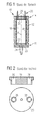
- Figs. 1 and 2 illustrate the structure of a conventional one Actuator 10, which is an upper assembly of a Fuel injector unit forms in its lower area a fuel injector (not shown) having.
- the actuator 10 is used in the following Way for controlled actuation of this injector.
- the actuator 10 includes in a conventional manner a sleeve-like, here essentially hollow cylindrical housing 12 with a longitudinal axis A extending from an upper end 14 of the Housing extends to a lower end 16 of the housing, a arranged in the housing 12 piezoelectric actuator 18, for a Length change in the axial direction can be controlled, an am upper end 14 of the housing 12 welded housing head 20, at which the upper end of the piezoelectric actuator 18 in the axial direction supported, one movable in the axial direction in the housing 12 guided actuator base 22, at which the lower End of the piezoelectric actuator 18 is supported in the axial direction, and a axially movable valve piston 24 of the injection valve, which is in operative connection with the actuator bottom 22, by an axial length change of the piezoelectric actuator 18 to the valve piston 24 to transfer.
- This active compound is by direct attachment of a down protruding portion of the actuator base 22 at an upper Contact surface of the valve piston 24 realized.
- a diaphragm ring 25 is provided, whose outer circumference with the inside of the housing is welded and its inner circumference with the outer circumference of the downwardly projecting Aktorêtabitess is welded.
- This membrane ring 25 is comparatively thin, so that this when controlling the piezoelectric actuator 18th can deform elastically.
- the active compound can also be realized in other ways be, z. B. by a lever translator as in the beginning DE 198 58 085 C1 already mentioned.
- diaphragm ring 25 could alternatively as an between Actuator bottom 22 and valve piston 24 through and only provided on the housing inner wall welded disc be.
- the injector may be z. B. act to a servo injection valve, which by means of Piezoactuator 18 is actuated, wherein the initiation of a Injection process a pressure reduction in a control room which in turn causes movement of an injector nozzle body (Nozzle needle) in the direction of an opening of a Injection passage causes between a nozzle space of the Injection valve and a combustion chamber of an internal combustion engine is provided.
- a servo injection valve which by means of Piezoactuator 18 is actuated, wherein the initiation of a Injection process a pressure reduction in a control room which in turn causes movement of an injector nozzle body (Nozzle needle) in the direction of an opening of a Injection passage causes between a nozzle space of the Injection valve and a combustion chamber of an internal combustion engine is provided.
- a significant advantage of using a means of a piezoelectric actuator operated servo injection valve is it, that with a comparatively small stroke (in the micron range) the piezoelectric actuator one of them more independent, as a rule be achieved by a multiple larger stroke of the nozzle body can (hydraulic stroke ratio).
- the advantage that the movement of the nozzle body for Opening and closing the injection passage by the pressure of the Fuel is used for the purposes of injection in the combustion chamber anyway under relatively high pressure standing in the area of the injection valve ready. For the Control of the injector therefore satisfies an actuator with comparatively small stroke and comparatively low actuator force.
- the piezoelectric actuator 18 of the actuator 10 has a stack on one another lying piezo elements, which when creating a electrical voltage via a contact pin assembly 26th rapidly its axial extension about a voltage-dependent Extent changed.
- suitable piezoelectric Ceramics are known in great variety, for example as Lead zirconate titanate ceramics.
- the problem in the operation of the fuel injector unit, that it is at a temperature change of the installation environment to thermal changes in shape of the individual components comes. These shape changes may be due to the diversity the materials used the performance characteristics and the driving characteristic of the actuator 10th or the injection valve actuated therewith depending on the temperature change.
- this housing head 20 is at the periphery both with the upper housing end 14 and with the upper end of a Welded tube spring 30 whose lower end is welded to the circumference of the actuator base 22 and which pre-loads the piezoceramic to pressure in the axial direction (compressive force about 1x10 3 N). This preload reduces the dynamic loads occurring during operation of the extremely zuzupfindlichen piezoceramic.
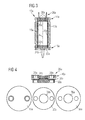
- Fig. 3 shows an actuator 10a, in which a housing head 20a as a thermo-bimetal unit to compensate for temperature-dependent change of the axial positional relationships in Region of the active connection is formed.
- the realized with it Temperature compensation is based on an axial displacement the piezoelectric actuator 18a relative to the housing 12a.
- the structure of this modified housing head 20a is more detailed shown in Fig. 4.
- the housing head 20a is in total plate-shaped and consists of three parts.
- One lower part is formed by a steel plate 32a, which has a survey 34a in its center.
- This survey 34a passes through a central opening 36a of a membrane ring 38a (steel) formed middle part.
- An upper one Part is finally of a vaulted bimetallic plate 40a formed, the downwardly facing convex end face abuts the elevation 34a.
- the plate 32a is at its peripheral edge with the tube spring 30a welds and transmits the biasing force of the tube spring 30a on the ceramic body of the piezoelectric actuator 18a.
- the membrane ring 38a and the bimetallic plate 40a are at their outer Peripheral edges welded to the upper housing end 14a.
- both the diaphragm ring 38a and the lower steel plate 32a could be omitted in principle, then meet this Components in the illustrated embodiment very advantageous Functions.
- the plate 32a acts for equalization and radial distribution between the housing head 20a and the piezoelectric actuator 18a acting axial force.
- this feature also by a suitably trained and supported on the tube spring end Cover layer realized at the upper end of the piezoelectric actuator 18a could be.
- the welded membrane ring 38a leaves a Movement of the steel plate 32a in the axial direction, fixed but their position in the radial direction, with a guide the steel plate 32a by means of the central opening 36a of the Membrane ring 38a is realized.
- Thermobimetallplatte 40a has in its central region an approximately spherical cap-shaped curvature, which on the one hand a position of the contact point which is as constant as possible the lower disc 32a ensures and on the other hand the elastic stiffness compared to a principle as well conceivable flat design advantageously increased.
- Deviating from the illustrated embodiment could alternatively or in addition also another installation place for the Thermobimetal be provided, for example, directly above or below the actuator bottom 22a.
- thermostatic bimetal unit (s) By using the thermostatic bimetal unit (s) it comes to a greatly increased freedom in the choice of materials Components of the actuator and the device operated therewith. Thus, for the particularly material-intensive Components such as the housing 12 a, a relatively inexpensive Material like steel can be used. Regarding the material choice in the actuator 10a are below only exemplified two options.
- valve piston 24a from inexpensive and easy to process steel (high thermal expansion coefficient) and the housing 12a made of an iron-nickel alloy (very low thermal expansion coefficient) be prepared.
- This material combination comes in usually to overcompensation of thermal changes in length, so that the bimetal plate is to be installed here, that their convex curvature at a temperature increase retracts from the piezoelectric actuator 18a.
- the bimetallic plate should 40a be made relatively thick (The thermally induced Deflection of a bimetallic composite is strongly influenced by the Thickness dependent). Such a relatively thick version brings a high elastic stiffness in the axial direction with it.
- the Bimetallic plate 40a is here (inverse to that described above Case) designed such that their point of contact with the steel disk 32a at temperature increase shifts toward the piezoelectric actuator 18a. Besides, this one is Run the bimetallic plate 40a expediently thinner executed, since here almost the entire axial thermal length change of the housing 12a is to compensate. This material selection brings in comparison to the above-explained Case another cost advantage due to the use of steel for the housing 12a.
Landscapes
- Engineering & Computer Science (AREA)
- Chemical & Material Sciences (AREA)
- Combustion & Propulsion (AREA)
- Mechanical Engineering (AREA)
- General Engineering & Computer Science (AREA)
- Fuel-Injection Apparatus (AREA)
Abstract
Description
- Fig. 1
- einen Axiallängsschnitt eines Stellantriebs nach dem Stand der Technik,
- Fig. 2
- eine Schnittansicht (Fig. 2 oben) sowie eine Draufsicht (Fig. 2 unten) einer in dem Stellantrieb von Fig. 1 verwendeten Kopfplatte,
- Fig. 3
- einen Axiallängsschnitt eines Stellantriebs gemäß eines ersten Ausführungsbeispiels der Erfindung, und
- Fig. 4
- eine Schnittansicht (Fig. 4 oben) eines in dem Stellantrieb von Fig. 3 verwendeten Gehäusekopfes sowie Draufsichten (Fig. 4 unten) der drei Gehäusekopfkomponenten.
Claims (17)
- Stellantrieb für einen Kraftstoffinjektor einer Brennkraftmaschine, umfassenddadurch gekennzeichnet, dass in der Gehäuseanordnung (12a) wenigstens eine Thermobimetalleinheit angeordnet ist, um eine temperaturabhängige Änderung der axialen Lageverhältnisse im Bereich der Wirkverbindung wenigstens teilweise zu kompensieren.eine hülsenförmige Gehäuseanordnung (12a) mit einer Axialrichtung (A), die sich zwischen einem ersten und einem zweiten Ende (14a, 16a) der Gehäuseanordnung erstreckt,einen in der Gehäuseanordnung (12a) angeordneten und für eine Längenänderung in Axialrichtung (A) ansteuerbaren Piezoaktor (18a),einen in Axialrichtung (A) festgelegten Gehäusekopf (20a) am ersten Ende (14a) der Gehäuseanordnung(12a), an welchem sich ein erstes Ende des Piezoaktors (18a) in Axialrichtung abstützt,einen in Axialrichtung (A) bewegbar in der Gehäuseanordnung (12a) geführten Aktorboden (22a), an welchem sich ein zweites Ende des Piezoaktors (18a) in Axialrichtung abstützt, und
- Stellantrieb nach Anspruch 1, wobei die Thermobimetalleinheit (40a) eine gewölbte Thermobimetallplatte umfasst, deren konvexe Stirnseite an einer weiteren, ebenen Platte (32a) anliegt, um diese bei einer Temperaturänderung in Axialrichtung (A) zu verschieben.
- Stellantrieb nach einem der vorangehenden Ansprüche, wobei der Gehäusekopf (20a) als die Thermobimetalleinheit ausgebildet ist oder die Thermobimetalleinheit enthält.
- Stellantrieb nach einem der vorangehenden Ansprüche, wobei der Aktorboden (22a) als die Thermobimetalleinheit ausgebildet ist oder die Thermobimetalleinheit enthält.
- Stellantrieb nach einem der vorangehenden Ansprüche, wobei das Stellglied (24a) als die Thermobimetalleinheit ausgebildet ist oder die Thermobimetalleinheit enthält.
- Stellantrieb nach einem der vorangehenden Ansprüche, wobei die Thermobimetalleinheit in der Gehäuseanordnung (12a) derart angeordnet ist, dass bei Temperaturänderung eine axiale Verlagerung des Piezoaktors (18a) gegenüber der Gehäuseanordnung (12a) bewirkt wird.
- Stellantrieb nach einem der vorangehenden Ansprüche, wobei die Thermobimetalleinheit in der Gehäuseanordnung (12a) derart angeordnet ist, dass bei Temperaturänderung eine axiale Verlagerung des Stellglieds (24a) gegenüber dem Aktorboden (22a) bewirkt wird.
- Stellantrieb nach einem der vorangehenden Ansprüche, wobei die Gehäuseanordnung (12a) wenigstens teilweise aus Stahl hergestellt ist.
- Stellantrieb nach einem der vorangehenden Ansprüche, wobei ein Abschnitt des Gehäusekopfes (20a) mit der Gehäuseanordnung (12a) verschweißt ist.
- Stellantrieb nach einem der vorangehenden Ansprüche, wobei der Gehäusekopf (20a) plattenförmig ausgebildet ist.
- Stellantrieb nach einem der vorangehenden Ansprüche, wobei der Aktorboden (22a) einen dem Piezoaktor zugewandten, plattenförmig ausgebildeten Abschnitt aufweist.
- Stellantrieb nach einem der vorangehenden Ansprüche, wobei der Piezoaktor (18a) ein in Axialrichtung langgestreckter Piezoelementstapel ist.
- Stellantrieb nach einem der vorangehenden Ansprüche, wobei der Piezoaktor (18a) in einer sich über die gesamte axiale Länge desselben erstreckenden Rohrfeder (30a) angeordnet ist, deren Enden im Bereich des Gehäusekopfes (20a) und am Aktorboden (22a) festgelegt sind und welche den Piezoaktor in Axialrichtung auf Druck vorbelastet.
- Stellantrieb nach einem der vorhergehenden Ansprüche, dadurch gekennzeichnet, ein in Axialrichtung (A) bewegbar geführtes Stellglied (24a), welches in Wirkverbindung mit dem Aktorboden (22a) steht, um eine Axiallängenänderung des Piezoaktors (18a) auf das Stellglied (24a) zu übertragen,
- Stellantrieb nach einem der vorangehenden Ansprüche, wobei das Stellglied (24a) größtenteils aus Stahl hergestellt ist.
- Stellantrieb nach einem der vorangehenden Ansprüche, wobei das Stellglied (24a) als Ventilbetätigungskolben eines Hydraulikventils ausgebildet ist.
- Verwendung eines Stellantriebs (10a) nach einem der Ansprüche 1 bis 15 für einen Kraftstoffinjektor eines Common-Rail-Dieseleinspritzsystems.
Applications Claiming Priority (2)
| Application Number | Priority Date | Filing Date | Title |
|---|---|---|---|
| DE102004029363 | 2004-06-17 | ||
| DE102004029363A DE102004029363B4 (de) | 2004-06-17 | 2004-06-17 | Piezoelektrischer Stellantrieb für einen Kraftstoffinjektor einer Brennkraftmaschine sowie Verwendung hierfür |
Publications (2)
| Publication Number | Publication Date |
|---|---|
| EP1607621A1 true EP1607621A1 (de) | 2005-12-21 |
| EP1607621B1 EP1607621B1 (de) | 2010-09-08 |
Family
ID=34940182
Family Applications (1)
| Application Number | Title | Priority Date | Filing Date |
|---|---|---|---|
| EP05105301A Expired - Lifetime EP1607621B1 (de) | 2004-06-17 | 2005-06-16 | Piezoelektrischer Stellantrieb für einen Kraftstoffinjektor einer Brennkraftmaschine sowie Verwendung hierfür |
Country Status (2)
| Country | Link |
|---|---|
| EP (1) | EP1607621B1 (de) |
| DE (2) | DE102004029363B4 (de) |
Cited By (1)
| Publication number | Priority date | Publication date | Assignee | Title |
|---|---|---|---|---|
| CN106062350A (zh) * | 2014-02-07 | 2016-10-26 | 艾克莫特公司 | 与压电燃料喷射器一起使用的预加载弹簧 |
Citations (9)
| Publication number | Priority date | Publication date | Assignee | Title |
|---|---|---|---|---|
| US4437644A (en) * | 1979-08-06 | 1984-03-20 | Audi Nsu Auto Union Aktiengesellschaft | Electrically operable valve |
| EP0745766A2 (de) * | 1995-05-31 | 1996-12-04 | Siemens Automotive Corporation | Thermostatische Luftregelung für einen luftunterstützes Kraftstoffeinspritzventil |
| DE19538791A1 (de) * | 1995-10-18 | 1997-04-24 | Daimler Benz Ag | Piezosteuerventil für Kraftstoffeinspritzanlagen von Brennkraftmaschinen |
| JPH109084A (ja) * | 1996-06-24 | 1998-01-13 | Nissan Motor Co Ltd | 圧電式燃料噴射弁 |
| DE19858085C1 (de) * | 1998-12-16 | 2000-03-30 | Siemens Ag | Stellantrieb für einen Kraftstoffinjektor |
| DE10130857A1 (de) * | 2000-06-30 | 2002-03-14 | Siemens Automotive Corp Lp | Elektronischer Kompensator für ein piezoelektrisches Betätigungsglied |
| US6422482B1 (en) * | 1998-10-26 | 2002-07-23 | Robert Bosch Gmbh | Fuel injection valve |
| EP1256711A1 (de) * | 2001-05-08 | 2002-11-13 | MAGNETI MARELLI POWERTRAIN S.p.A. | Kraftstoffeinspritzventil mit piezoelektrischem Aktor |
| WO2003052260A1 (de) * | 2001-12-18 | 2003-06-26 | Robert Bosch Gmbh | Brennstoffeinspritzventil |
Family Cites Families (1)
| Publication number | Priority date | Publication date | Assignee | Title |
|---|---|---|---|---|
| DE10319601A1 (de) * | 2003-05-02 | 2004-11-18 | Robert Bosch Gmbh | Aktoreinheit für ein piezogesteuertes Kraftstoffeinspritzventil |
-
2004
- 2004-06-17 DE DE102004029363A patent/DE102004029363B4/de not_active Expired - Fee Related
-
2005
- 2005-06-16 DE DE502005010201T patent/DE502005010201D1/de not_active Expired - Lifetime
- 2005-06-16 EP EP05105301A patent/EP1607621B1/de not_active Expired - Lifetime
Patent Citations (9)
| Publication number | Priority date | Publication date | Assignee | Title |
|---|---|---|---|---|
| US4437644A (en) * | 1979-08-06 | 1984-03-20 | Audi Nsu Auto Union Aktiengesellschaft | Electrically operable valve |
| EP0745766A2 (de) * | 1995-05-31 | 1996-12-04 | Siemens Automotive Corporation | Thermostatische Luftregelung für einen luftunterstützes Kraftstoffeinspritzventil |
| DE19538791A1 (de) * | 1995-10-18 | 1997-04-24 | Daimler Benz Ag | Piezosteuerventil für Kraftstoffeinspritzanlagen von Brennkraftmaschinen |
| JPH109084A (ja) * | 1996-06-24 | 1998-01-13 | Nissan Motor Co Ltd | 圧電式燃料噴射弁 |
| US6422482B1 (en) * | 1998-10-26 | 2002-07-23 | Robert Bosch Gmbh | Fuel injection valve |
| DE19858085C1 (de) * | 1998-12-16 | 2000-03-30 | Siemens Ag | Stellantrieb für einen Kraftstoffinjektor |
| DE10130857A1 (de) * | 2000-06-30 | 2002-03-14 | Siemens Automotive Corp Lp | Elektronischer Kompensator für ein piezoelektrisches Betätigungsglied |
| EP1256711A1 (de) * | 2001-05-08 | 2002-11-13 | MAGNETI MARELLI POWERTRAIN S.p.A. | Kraftstoffeinspritzventil mit piezoelektrischem Aktor |
| WO2003052260A1 (de) * | 2001-12-18 | 2003-06-26 | Robert Bosch Gmbh | Brennstoffeinspritzventil |
Non-Patent Citations (1)
| Title |
|---|
| PATENT ABSTRACTS OF JAPAN vol. 1998, no. 05 30 April 1998 (1998-04-30) * |
Cited By (1)
| Publication number | Priority date | Publication date | Assignee | Title |
|---|---|---|---|---|
| CN106062350A (zh) * | 2014-02-07 | 2016-10-26 | 艾克莫特公司 | 与压电燃料喷射器一起使用的预加载弹簧 |
Also Published As
| Publication number | Publication date |
|---|---|
| DE102004029363A1 (de) | 2006-01-12 |
| EP1607621B1 (de) | 2010-09-08 |
| DE502005010201D1 (de) | 2010-10-21 |
| DE102004029363B4 (de) | 2007-10-11 |
Similar Documents
| Publication | Publication Date | Title |
|---|---|---|
| EP1642018B1 (de) | Ventilvorrichtung und verfahren zum einblasen von gasförmigem kraftstoff | |
| EP1045973B1 (de) | Brennstoffeinspritzventil | |
| DE112012000505B4 (de) | Kraftstoffeinspritzdüse mit einem piezoelektrischen Aktuator und einer Sensoranordnung | |
| DE3205654A1 (de) | Dosierventil | |
| DE2931874A1 (de) | Elektrisch betaetigbares ventil | |
| DE19946838C1 (de) | Ventil zum Steuern von Flüssigkeiten | |
| EP0864743B1 (de) | Kraftstoffeinspritzventil für Brennkraftmaschinen | |
| EP1567765B1 (de) | Einspritzventil | |
| EP1092089B1 (de) | Brennstoffeinspritzventil und verfahren zu dessen betätigung | |
| EP1144841A2 (de) | Verfahren zum positionieren des stellantriebs in einem kraftstoffinjektor und vorrichtung zur durchführung des verfahrens | |
| DE19947779A1 (de) | Brennstoffeinspritzventil | |
| EP1705369A1 (de) | Kraftstoffinjektor für Verbrennungskraftmaschinen | |
| WO2001014731A1 (de) | Ventil zum steuern von flüssigkeiten | |
| WO2002057622A1 (de) | Ventil zum steuern von flüssigkeiten | |
| EP1759114A1 (de) | Kraftstoffinjektor mit variabler aktorhubübersetzung | |
| DE19939476C2 (de) | Ventil zum Steuern von Flüssigkeiten | |
| EP1531258A2 (de) | Kraftstoffeinspritzventil | |
| EP1607621B1 (de) | Piezoelektrischer Stellantrieb für einen Kraftstoffinjektor einer Brennkraftmaschine sowie Verwendung hierfür | |
| DE102005028400A1 (de) | Kraftstoffeinspritzvorrichtung für ein Kraftstoffeinspritzsystem | |
| DE19946839A1 (de) | Verstelleinrichtung zum Ansteuern einer Regel- und/oder Absperrvorrichtung | |
| EP1916414A2 (de) | Kraftstoffinjektor mit Piezoaktor | |
| DE102004030606B4 (de) | Piezoelektrischer Stellantrieb für einen Kraftstoffinjektor einer Brennkraftmaschine | |
| DE10002720A1 (de) | Ventil zum Steuern von Flüssigkeiten | |
| WO2001029401A1 (de) | Brennstoffeinspritzventil | |
| DE60302329T2 (de) | Kompensator zum Ausgleich von Wärmedehnungen für eine Dosiervorrichtung |
Legal Events
| Date | Code | Title | Description |
|---|---|---|---|
| PUAI | Public reference made under article 153(3) epc to a published international application that has entered the european phase |
Free format text: ORIGINAL CODE: 0009012 |
|
| AK | Designated contracting states |
Kind code of ref document: A1 Designated state(s): AT BE BG CH CY CZ DE DK EE ES FI FR GB GR HU IE IS IT LI LT LU MC NL PL PT RO SE SI SK TR |
|
| AX | Request for extension of the european patent |
Extension state: AL BA HR LV MK YU |
|
| 17P | Request for examination filed |
Effective date: 20060123 |
|
| AKX | Designation fees paid |
Designated state(s): DE FR GB IT |
|
| RAP1 | Party data changed (applicant data changed or rights of an application transferred) |
Owner name: CONTINENTAL AUTOMOTIVE GMBH |
|
| GRAP | Despatch of communication of intention to grant a patent |
Free format text: ORIGINAL CODE: EPIDOSNIGR1 |
|
| GRAS | Grant fee paid |
Free format text: ORIGINAL CODE: EPIDOSNIGR3 |
|
| GRAA | (expected) grant |
Free format text: ORIGINAL CODE: 0009210 |
|
| AK | Designated contracting states |
Kind code of ref document: B1 Designated state(s): DE FR GB IT |
|
| REG | Reference to a national code |
Ref country code: GB Ref legal event code: FG4D Free format text: NOT ENGLISH |
|
| REF | Corresponds to: |
Ref document number: 502005010201 Country of ref document: DE Date of ref document: 20101021 Kind code of ref document: P |
|
| PG25 | Lapsed in a contracting state [announced via postgrant information from national office to epo] |
Ref country code: IT Free format text: LAPSE BECAUSE OF FAILURE TO SUBMIT A TRANSLATION OF THE DESCRIPTION OR TO PAY THE FEE WITHIN THE PRESCRIBED TIME-LIMIT Effective date: 20100908 |
|
| PLBE | No opposition filed within time limit |
Free format text: ORIGINAL CODE: 0009261 |
|
| STAA | Information on the status of an ep patent application or granted ep patent |
Free format text: STATUS: NO OPPOSITION FILED WITHIN TIME LIMIT |
|
| 26N | No opposition filed |
Effective date: 20110609 |
|
| REG | Reference to a national code |
Ref country code: DE Ref legal event code: R097 Ref document number: 502005010201 Country of ref document: DE Effective date: 20110609 |
|
| GBPC | Gb: european patent ceased through non-payment of renewal fee |
Effective date: 20110616 |
|
| PG25 | Lapsed in a contracting state [announced via postgrant information from national office to epo] |
Ref country code: GB Free format text: LAPSE BECAUSE OF NON-PAYMENT OF DUE FEES Effective date: 20110616 |
|
| REG | Reference to a national code |
Ref country code: FR Ref legal event code: PLFP Year of fee payment: 12 |
|
| REG | Reference to a national code |
Ref country code: FR Ref legal event code: PLFP Year of fee payment: 13 |
|
| REG | Reference to a national code |
Ref country code: FR Ref legal event code: PLFP Year of fee payment: 14 |
|
| PGFP | Annual fee paid to national office [announced via postgrant information from national office to epo] |
Ref country code: DE Payment date: 20180630 Year of fee payment: 14 |
|
| PGFP | Annual fee paid to national office [announced via postgrant information from national office to epo] |
Ref country code: FR Payment date: 20180626 Year of fee payment: 14 |
|
| REG | Reference to a national code |
Ref country code: DE Ref legal event code: R119 Ref document number: 502005010201 Country of ref document: DE |
|
| PG25 | Lapsed in a contracting state [announced via postgrant information from national office to epo] |
Ref country code: DE Free format text: LAPSE BECAUSE OF NON-PAYMENT OF DUE FEES Effective date: 20200101 |
|
| PG25 | Lapsed in a contracting state [announced via postgrant information from national office to epo] |
Ref country code: FR Free format text: LAPSE BECAUSE OF NON-PAYMENT OF DUE FEES Effective date: 20190630 |