EP1607600B1 - Device for operating a fan - Google Patents
Device for operating a fan Download PDFInfo
- Publication number
- EP1607600B1 EP1607600B1 EP05105038A EP05105038A EP1607600B1 EP 1607600 B1 EP1607600 B1 EP 1607600B1 EP 05105038 A EP05105038 A EP 05105038A EP 05105038 A EP05105038 A EP 05105038A EP 1607600 B1 EP1607600 B1 EP 1607600B1
- Authority
- EP
- European Patent Office
- Prior art keywords
- fan
- hydraulic
- hydraulic pump
- internal combustion
- combustion engine
- Prior art date
- Legal status (The legal status is an assumption and is not a legal conclusion. Google has not performed a legal analysis and makes no representation as to the accuracy of the status listed.)
- Expired - Fee Related
Links
Images
Classifications
-
- F—MECHANICAL ENGINEERING; LIGHTING; HEATING; WEAPONS; BLASTING
- F01—MACHINES OR ENGINES IN GENERAL; ENGINE PLANTS IN GENERAL; STEAM ENGINES
- F01P—COOLING OF MACHINES OR ENGINES IN GENERAL; COOLING OF INTERNAL-COMBUSTION ENGINES
- F01P7/00—Controlling of coolant flow
- F01P7/02—Controlling of coolant flow the coolant being cooling-air
- F01P7/04—Controlling of coolant flow the coolant being cooling-air by varying pump speed, e.g. by changing pump-drive gear ratio
- F01P7/044—Controlling of coolant flow the coolant being cooling-air by varying pump speed, e.g. by changing pump-drive gear ratio using hydraulic drives
-
- F—MECHANICAL ENGINEERING; LIGHTING; HEATING; WEAPONS; BLASTING
- F01—MACHINES OR ENGINES IN GENERAL; ENGINE PLANTS IN GENERAL; STEAM ENGINES
- F01P—COOLING OF MACHINES OR ENGINES IN GENERAL; COOLING OF INTERNAL-COMBUSTION ENGINES
- F01P7/00—Controlling of coolant flow
- F01P7/14—Controlling of coolant flow the coolant being liquid
- F01P7/16—Controlling of coolant flow the coolant being liquid by thermostatic control
- F01P7/167—Controlling of coolant flow the coolant being liquid by thermostatic control by adjusting the pre-set temperature according to engine parameters, e.g. engine load, engine speed
Definitions
- the invention relates to a device for operating a fan for a radiator of an internal combustion engine according to the preamble of patent claim 1.
- An internal combustion engine e.g. a diesel engine, which is intended in particular for driving a diesel locomotive, has a cooling system for heat dissipation.
- a cooling system for heat dissipation.
- the radiator is associated with a fan which generates in the manner of a fan, an air flow, which is directed to the radiator.
- a hydraulic motor is provided, which is part of a hydraulic circuit.
- Such hydraulic circuits are known. There is a distinction between an open and a closed circuit.
- a hydraulic pump sucks a hydraulic fluid from a reservoir via a filter and a diffuser. The hydraulic fluid then passes from the hydraulic pump to the hydraulic motor to drive it, and from there flows back to the reservoir via an associated hydraulic cooler and filter.
- a closed circuit the hydraulic fluid flows from the hydraulic pump to the hydraulic motor and from there back to the hydraulic pump. Only a small subset of the hydraulic fluid can be removed via a so-called rinsing block on the low pressure side of the hydraulic circuit and replaced by a feed pump from a container. This has the aim to dissipate a possible heat input.
- the cooling capacity of the fan is therefore not optimally adaptable to the existing temperature in the radiator of the internal combustion engine in the known.
- the invention has for its object to provide a device for operating a fan for a radiator of an internal combustion engine, which ensures an always reliable, according to the requirements cooling of the cooling liquid in the radiator by the fan.
- the speed of the fan can be limited by an associated limit value transmitter, which has stored a maximum value for the speed of the fan. This provides another possibility to avoid overloading the fan.
- a hydraulic pump is part of the closed hydraulic circuit.
- the delivery volume of the hydraulic pump for controlling the speed of the fan is adjustable. This advantageously saves previously necessary, expensive control valves.
- the delivery volume of the hydraulic pump can be regulated as a function of the rotational speed of the internal combustion engine.
- hydraulic motor is directly coupled to the fan. Elaborate additional components are not needed.
- the volume flow in the closed hydraulic circuit for easy control of the speed of the fan is adjustable.
- a volume flow regulator is arranged in the closed hydraulic circuit.
- a volumetric flow controller becomes active only from a certain volumetric flow, which would lead to too high a speed of the fan, and then prevents a further increase in the volumetric flow to the hydraulic motor.
- the advantage is achieved that the fan is not overloaded and the hydraulic motor can be operated energetically low.
- the fan speed rises from a first speed of the engine controlled and reaches at a second speed of the engine, a maximum value that remains unchanged in a further increase in the speed of the engine.
- a speed of the internal combustion engine which is smaller than said first speed of the internal combustion engine, cooling is not required. The fan then stops.
- this is connected to the internal combustion engine. It is thus ensured that the hydraulic circuit is in operation, even if the internal combustion engine is in operation.
- the hydraulic pump is connected directly to the internal combustion engine. This results in the advantage that the rotational speed of the hydraulic pump and thus also the fan speed increases or decreases with the speed of the internal combustion engine.
- the delivery volume of the hydraulic pump and thus the performance of the fan thus depends directly on the speed of the engine and thus on the temperature of the coolant.
- the delivery volume of the hydraulic pump in dependence on the temperature of the cooling liquid in the cooler associated with the cooling system can be controlled.
- the cooling liquid is reliably cooled.
- the delivery volume of the hydraulic pump can be regulated by changing the pivot angle of a swash plate arranged in the hydraulic pump.
- the advantage is achieved that an optimal, low-energy cooling via the fan with simple, inexpensive components can be achieved.
- a railcar e.g. a diesel locomotive
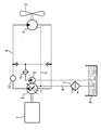
- An internal combustion engine 1 which drives a vehicle, in particular a rail vehicle, is associated with a cooling system, not shown, which contains a cooler for cooling liquid.
- This cooler is associated with a fan 2, which cools the cooler and thus the cooling liquid by generating an air flow.
- the fan 2 is driven by a hydraulic motor 3, which is part of a closed hydraulic circuit 4. Hydraulic fluid in the closed hydraulic circuit 4 is moved by a hydraulic pump 5 arranged there, which is driven by the internal combustion engine 1.
- either the pivot angle of a swash plate 11 in the hydraulic pump 5 can be changed or it can be a volume flow controller 12 are operated in the closed hydraulic circuit 4.
- Both a servo valve or a proportional valve for changing the swivel angle of the swash plate 11, as well as the volumetric flow controller 12, depending on the measured speed of the engine 1 can be controlled so that a desired volume flow in the closed hydraulic circuit 4 and thus a desired speed of the fan. 2 established. It is particularly important that the speed of the fan 2 can not exceed a maximum value even with further increasing speed of the internal combustion engine 1.
- Both an adjustable swivel disk 11 in the hydraulic pump 5 and a volumetric flow controller 12 in the closed hydraulic circuit 4 can also be present.
Landscapes
- Engineering & Computer Science (AREA)
- Chemical & Material Sciences (AREA)
- Combustion & Propulsion (AREA)
- Mechanical Engineering (AREA)
- General Engineering & Computer Science (AREA)
- Fluid-Pressure Circuits (AREA)
- Auxiliary Drives, Propulsion Controls, And Safety Devices (AREA)
- Eye Examination Apparatus (AREA)
- Power Steering Mechanism (AREA)
- Control Of Electric Motors In General (AREA)
- Cooling, Air Intake And Gas Exhaust, And Fuel Tank Arrangements In Propulsion Units (AREA)
Abstract
Description
Die Erfindung betrifft eine Vorrichtung zum Betreiben eines Lüfters für einen Kühler eines Verbrennungsmotors nach dem Oberbegriff des Patentanspruches 1.The invention relates to a device for operating a fan for a radiator of an internal combustion engine according to the preamble of patent claim 1.
Ein Verbrennungsmotor, z.B. ein Dieselmotor, der insbesondere zum Antreiben einer Diesellokomotive bestimmt ist, weist zur Wärmeabfuhr eine Kühlanlage auf. Bestandteil dieser Kühlanlage ist ein Kühler, in dem zuvor im Motor erhitzte Kühlflüssigkeit wieder abgekühlt wird. Dazu ist dem Kühler ein Lüfter zugeordnet, der in der Art eines Ventilators einen Luftstrom erzeugt, der auf den Kühler gerichtet ist. Zum Antreiben dieses Lüfters ist ein Hydraulikmotor vorgesehen, der Teil eines Hydraulikkreislaufs ist.An internal combustion engine, e.g. a diesel engine, which is intended in particular for driving a diesel locomotive, has a cooling system for heat dissipation. Part of this cooling system is a cooler, in which previously heated in the engine coolant is cooled again. For this purpose, the radiator is associated with a fan which generates in the manner of a fan, an air flow, which is directed to the radiator. To drive this fan, a hydraulic motor is provided, which is part of a hydraulic circuit.
Derartige Hydraulikkreisläufe sind bekannt. Es wird zwischen einem offenen und einem geschlossenen Kreislauf unterschieden. Bei einem üblichen offenen Kreislauf saugt eine Hydraulikpumpe eine Hydraulikflüssigkeit aus einem Behälter über ein Filter und einen Diffusor an. Die Hydraulikflüssigkeit gelangt dann von der Hydraulikpumpe zum Hydraulikmotor, um diesen anzutreiben, und fließt von dort über einen zugeordneten Hydraulikkühler und einen Filter zum Behälter zurück. Bei einem geschlossenen Kreislauf strömt die Hydraulikflüssigkeit von der Hydraulikpumpe zum Hydraulikmotor und von dort zurück zur Hydraulikpumpe. Nur eine kleine Teilmenge der Hydraulikflüssigkeit kann über einen sogenannten Spülblock auf der Niederdruckseite aus dem Hydraulikkreislauf herausgenommen und über eine Speisepumpe aus einem Behälter ersetzt werden. Das hat zum Ziel, einen möglichen Wärmeeintrag abzuführen.Such hydraulic circuits are known. There is a distinction between an open and a closed circuit. In a conventional open circuit, a hydraulic pump sucks a hydraulic fluid from a reservoir via a filter and a diffuser. The hydraulic fluid then passes from the hydraulic pump to the hydraulic motor to drive it, and from there flows back to the reservoir via an associated hydraulic cooler and filter. In a closed circuit, the hydraulic fluid flows from the hydraulic pump to the hydraulic motor and from there back to the hydraulic pump. Only a small subset of the hydraulic fluid can be removed via a so-called rinsing block on the low pressure side of the hydraulic circuit and replaced by a feed pump from a container. This has the aim to dissipate a possible heat input.
Bisher wurde zum Betreiben eines Lüfters für einen Kühler eines Verbrennungsmotors stets ein offener Hydraulikkreislauf bevorzugt. Dort wären aber zur Regelung der Lüfterdrehzahl aufwändige, elektrisch verstellbare Proportionalventile erforderlich, die einen Teilstrom der Hydraulikflüssigkeit energetisch ungenützt am Hydraulikmotor vorbeileiten.So far, to operate a fan for a radiator of an internal combustion engine has always been an open hydraulic circuit prefers. But there would be complicated, electrically adjustable proportional valves are required to control the fan speed, which bypass a partial flow of the hydraulic fluid energetically unused to the hydraulic motor.
Aus der Patentschrift
Die Kühlleistung des Lüfters ist also beim Bekannten nicht in optimaler Weise an die jeweils vorhandene Temperatur im Kühler des Verbrennungsmotors anpassbar.The cooling capacity of the fan is therefore not optimally adaptable to the existing temperature in the radiator of the internal combustion engine in the known.
Der Erfindung liegt die Aufgabe zugrunde, eine Vorrichtung zum Betreiben eines Lüfters für einen Kühler eines Verbrennungsmotors anzugeben, die eine stets zuverlässige, den Erfordernissen entsprechende Kühlung der Kühlflüssigkeit im Kühler durch den Lüfter gewährleistet.The invention has for its object to provide a device for operating a fan for a radiator of an internal combustion engine, which ensures an always reliable, according to the requirements cooling of the cooling liquid in the radiator by the fan.
Die Aufgabe wird gemäß der Erfindung gelöst durch eine gattungsgemäße Vorrichtung mit den kennzeichnenden Merkmalen des Patentanspruches 1.The object is achieved according to the invention by a generic device with the characterizing features of claim 1.
Damit wird der Vorteil erzielt, dass durch eine Regelung von in einem geschlossenen Hydraulikkreislauf angeordneten Bauteilen in einfacher, energetisch günstiger Weise eine den Anforderungen entsprechende Regelung der Lüfterdrehzahl zu erreichen ist. Elektrisch verstellbare Proportionalventile können eingespart werden. Mit dem Einsatz eines geschlossenen Hydraulikkreislaufs wird darüber hinaus der Diffusor eingespart und man kommt mit einem kleineren Behälter für Hydraulikflüssigkeit aus, da nur ein kleiner Teil der Hydraulikflüssigkeit ausgetauscht wird. Falls ein Hydraulikkühler vorhanden ist, muss dieser nur für die relativ kleine Austauschrate der Hydraulikflüssigkeit ausgelegt sein, da er nur die in den kleinen Behälter zurückgeleitete Hydraulikflüssigkeit zu kühlen hat. Ebenso ist auch nur ein kleiner Filter notwendig, der in der Zuleitung für die geringe Menge neu einzuspeisender Hydraulikflüssigkeit angeordnet ist. Die Vorrichtung nach der Erfindung ist deutlich kostengünstiger aufzubauen als eine bekannte Vorrichtung zum Betreiben eines Lüfters. Insbesondere aber ist die Vorrichtung nach der Erfindung besonders einfach und energetisch günstig regelbar.This provides the advantage that a regulation of the fan speed corresponding to the requirements can be achieved by regulating components arranged in a closed hydraulic circuit in a simple, energy-efficient manner. Electrically adjustable proportional valves can be saved. With the use of a closed hydraulic circuit, moreover, the diffuser is saved and one manages with a smaller container for hydraulic fluid, since only a small part of the hydraulic fluid is exchanged. If a hydraulic cooler is present, it must be designed only for the relatively small exchange rate of the hydraulic fluid, since he only has to cool the hydraulic fluid returned to the small container. Likewise, only a small filter is necessary, which is arranged in the supply line for the small amount of new hydraulic fluid to be fed. The Device according to the invention is significantly cheaper to build than a known device for operation a fan. In particular, however, the device according to the invention is particularly simple and low energy controllable.
Erfindungsgemäß ist die Drehzahl des Lüfters durch einen ihm zugeordneten Grenzwertgeber begrenzbar, der einen Maximalwert für die Drehzahl des Lüfters gespeichert hat. Hierdurch ist eine weitere Möglichkeit gegeben, um eine Überlastung des Lüfters zu vermeiden.According to the invention, the speed of the fan can be limited by an associated limit value transmitter, which has stored a maximum value for the speed of the fan. This provides another possibility to avoid overloading the fan.
Erfindungsgemäß ist eine Hydraulikpumpe Bestandteil des geschlossenen Hydraulikkreislaufs.According to the invention, a hydraulic pump is part of the closed hydraulic circuit.
Erfindungsgemäß ist das Fördervolumen der Hydraulikpumpe zum Regeln der Drehzahl des Lüfters regelbar. Man spart dadurch vorteilhaft bisher notwendige, teuere Regelventile ein.According to the invention the delivery volume of the hydraulic pump for controlling the speed of the fan is adjustable. This advantageously saves previously necessary, expensive control valves.
Erfindungsgemäß ist das Fördervolumen der Hydraulikpumpe abhängig von der Drehzahl des Verbrennungsmotors regelbar. Damit wird der Vorteil erzielt, dass gerade bei relativ hoher Drehzahl des Verbrennungsmotors keine unnötig hohe Leistung des Lüfters bereitgestellt wird.According to the invention, the delivery volume of the hydraulic pump can be regulated as a function of the rotational speed of the internal combustion engine. Thus, the advantage is achieved that especially at relatively high speed of the engine no unnecessarily high performance of the fan is provided.
Beispielsweise ist der Hydraulikmotor mit dem Lüfter direkt gekoppelt. Aufwändige Zusatzbauteile werden nicht benötigt.For example, the hydraulic motor is directly coupled to the fan. Elaborate additional components are not needed.
Beispielsweise ist der Volumenstrom im geschlossenen Hydraulikkreislauf zum einfachen Regeln der Drehzahl des Lüfters regelbar.For example, the volume flow in the closed hydraulic circuit for easy control of the speed of the fan is adjustable.
Dazu ist beispielsweise im geschlossenen Hydraulikkreislauf ein Volumenstromregler angeordnet. Ein solcher Volumenstromregler wird erst ab einem bestimmten Volumenstrom, der eine zu hohe Drehzahl des Lüfters nach sich ziehen würde, aktiv und verhindert dann ein weiteres Ansteigen des Volumenstroms zum Hydraulikmotor hin. Damit wird der Vorteil erzielt, dass der Lüfter nicht überlastet und der Hydraulikmotor energetisch günstig betrieben werden kann.For this purpose, for example, a volume flow regulator is arranged in the closed hydraulic circuit. Such a volumetric flow controller becomes active only from a certain volumetric flow, which would lead to too high a speed of the fan, and then prevents a further increase in the volumetric flow to the hydraulic motor. Thus, the advantage is achieved that the fan is not overloaded and the hydraulic motor can be operated energetically low.
Die Lüfterdrehzahl steigt ab einer ersten Drehzahl des Verbrennungsmotors geregelt an und erreicht bei einer zweiten Drehzahl des Verbrennungsmotors einen maximalen Wert, der bei einem weiteren Anstieg der Drehzahl des Verbrennungsmotors unverändert bleibt. Bei einer Drehzahl des Verbrennungsmotors, die kleiner ist als die genannte erste Drehzahl des Verbrennungsmotors, ist eine Kühlung nicht erforderlich. Der Lüfter steht dann still.The fan speed rises from a first speed of the engine controlled and reaches at a second speed of the engine, a maximum value that remains unchanged in a further increase in the speed of the engine. At a speed of the internal combustion engine, which is smaller than said first speed of the internal combustion engine, cooling is not required. The fan then stops.
Zum Antreiben der Hydraulikpumpe ist diese beispielsweise mit dem Verbrennungsmotor verbunden. Es ist somit sichergestellt, dass der Hydraulikkreislauf in Betrieb ist, wenn auch der Verbrennungsmotor in Betrieb ist.For driving the hydraulic pump, for example, this is connected to the internal combustion engine. It is thus ensured that the hydraulic circuit is in operation, even if the internal combustion engine is in operation.
Beispielsweise ist die Hydraulikpumpe direkt mit dem Verbrennungsmotor verbunden. Das ergibt den Vorteil, dass die Drehzahl der Hydraulikpumpe und damit auch die Lüfterdrehzahl mit der Drehzahl des Verbrennungsmotors ansteigt oder zurückgeht. Das Fördervolumen der Hydraulikpumpe und damit die Leistung des Lüfters hängt folglich direkt von der Drehzahl des Verbrennungsmotors und damit von der Temperatur der Kühlflüssigkeit ab.For example, the hydraulic pump is connected directly to the internal combustion engine. This results in the advantage that the rotational speed of the hydraulic pump and thus also the fan speed increases or decreases with the speed of the internal combustion engine. The delivery volume of the hydraulic pump and thus the performance of the fan thus depends directly on the speed of the engine and thus on the temperature of the coolant.
Beispielsweise ist das Fördervolumen der Hydraulikpumpe in Abhängigkeit von der Temperatur der Kühlflüssigkeit in der dem Kühler zugeordneten Kühlanlage regelbar. Dadurch wird die Kühlflüssigkeit zuverlässig gekühlt.For example, the delivery volume of the hydraulic pump in dependence on the temperature of the cooling liquid in the cooler associated with the cooling system can be controlled. As a result, the cooling liquid is reliably cooled.
Beispielsweise ist das Fördervolumen der Hydraulikpumpe durch Verändern des Schwenkwinkels einer in der Hydraulikpumpe angeordneten Schwenkscheibe regelbar.For example, the delivery volume of the hydraulic pump can be regulated by changing the pivot angle of a swash plate arranged in the hydraulic pump.
Zum Verstellen des Schwenkwinkels dient ein in der Pumpe vorhandenes Servoventil oder Proportionalventil. Es kann dazu auch eine elektrische Steuerung vorgesehen sein, der die gemessene Drehzahl des Verbrennungsmotors zuführbar ist.To adjust the pivot angle is used in the pump servo valve or proportional valve. It can also be provided for this purpose an electrical control, to which the measured rotational speed of the internal combustion engine can be fed.
Es kann vorteilhaft durch eine geeignete Einstellung des Schwenkwinkels der Schwenkscheibe in der Hydraulikpumpe erreicht werden, dass bei weiter ansteigender Drehzahl des Verbrennungsmotors die Drehzahl der Hydraulikpumpe und damit des Lüfters unverändert bleiben.It can be advantageously achieved by a suitable adjustment of the swivel angle of the swash plate in the hydraulic pump, that at further increasing speed of the engine, the speed of the hydraulic pump and thus the fan remain unchanged.
Man erreicht mit einfachen Mitteln eine optimale und energetisch günstige Regelung des Lüfters in Abhängigkeit von der Leistung des Verbrennungsmotors und damit in Abhängigkeit von der Temperatur der zu kühlenden Kühlflüssigkeit des Verbrennungsmotors.It achieves with simple means an optimal and energetically favorable control of the fan as a function of the performance of the internal combustion engine and thus in dependence on the temperature of the cooling liquid to be cooled of the internal combustion engine.
Mit der Vorrichtung zum Betreiben eines Lüfters nach der Erfindung wird der Vorteil erzielt, dass eine optimale, energetisch günstige Kühlung über den Lüfter mit einfachen, kostengünstigen Bauteilen erreichbar ist. Beim Einsatz in einem Fahzeug, insbesondere in einem Schienentriebfahrzeug, z.B. einer Diesellokomotive, ergibt sich ein deutlicher Kostenvorteil gegenüber bisher üblichen Vorrichtungen mit offenem Hydraulikkreislauf und Regelventilen, z.B. Proportionalventilen.With the device for operating a fan according to the invention, the advantage is achieved that an optimal, low-energy cooling via the fan with simple, inexpensive components can be achieved. When used in a vehicle, especially in a railcar, e.g. a diesel locomotive, there is a significant cost advantage over hitherto conventional devices with open hydraulic circuit and control valves, e.g. Proportional valves.
Die Vorrichtung zum Betreiben eines Lüfters nach der Erfindung wird anhand der Zeichnung näher erläutert:The device for operating a fan according to the invention will be explained in more detail with reference to the drawing:
Einem Verbrennungsmotor 1, der ein Fahrzeug, insbesondere ein Schienenfahrzeug, antreibt, ist eine nicht gezeigte Kühlanlage zugeordnet, die einen Kühler für Kühlflüssigkeit enthält. Diesem Kühler ist ein Lüfter 2 zugeordnet, der durch die Erzeugung eines Luftstromes den Kühler und damit die Kühlflüssigkeit abkühlt.An internal combustion engine 1, which drives a vehicle, in particular a rail vehicle, is associated with a cooling system, not shown, which contains a cooler for cooling liquid. This cooler is associated with a fan 2, which cools the cooler and thus the cooling liquid by generating an air flow.
Der Lüfter 2 wird durch einen Hydraulikmotor 3 angetrieben, der Teil eines geschlossenen Hydraulikkreislaufs 4 ist. Hydraulikflüssigkeit im geschlossenen Hydraulikkreislauf 4 wird durch eine dort angeordnete Hydraulikpumpe 5 bewegt, die vom Verbrennungsmotor 1 angetrieben wird.The fan 2 is driven by a hydraulic motor 3, which is part of a closed hydraulic circuit 4. Hydraulic fluid in the closed hydraulic circuit 4 is moved by a
Beim geschlossenen Hydraulikkreislauf 4 wird nur eine kleine Menge Hydraulikflüssigkeit über Leckleitungen 6 und einen Hydraulikkühler 7 in einen Behälter 8 geleitet. Von dort wird fehlende Hydraulikflüssigkeit über eine Speisepumpe 9 und ein Druckfilter 10 wieder in den geschlossenen Hydraulikkreislauf 4 eingespeist.In the closed hydraulic circuit 4, only a small amount of hydraulic fluid is passed via
Zur Regelung der Drehzahl des Hydraulikmotors 3 und damit des Lüfters 2 kann entweder der Schwenkwinkel einer Schwenkscheibe 11 in der Hydraulikpumpe 5 geändert werden oder es kann ein volumenstromregler 12 im geschlossenen Hydraulikkreislauf 4 betätigt werden. Sowohl ein Servoventil oder ein Proportionalventil zum Ändern des Schwenkwinkels der Schwenkscheibe 11, als auch der Volumenstromregler 12, können in Abhängigkeit der gemessenen Drehzahl des Verbrennungsmotors 1 so geregelt werden, dass sich ein gewünschter Volumenstrom im geschlossenen Hydraulikkreislauf 4 und damit eine gewünschte Drehzahl des Lüfters 2 einstellt. Dabei kommt es insbesondere darauf an, dass die Drehzahl des Lüfters 2 auch bei weiter ansteigender Drehzahl des Verbrennungsmotors 1 einen Maximalwert nicht übersteigen kann.To control the rotational speed of the hydraulic motor 3 and thus of the fan 2, either the pivot angle of a swash plate 11 in the
Zum Ansteuern des Servoventils oder Proportionalventils der Schwenkscheibe 11 und zum Ansteuern des Volumenstromreglers 12 sind nicht gezeigte Datenleitungen erforderlich.For driving the servo valve or proportional valve of the swash plate 11 and for controlling the
Es können auch sowohl eine einstellbare Schwenkscheibe 11 in der Hydraulikpumpe 5 als auch ein Volumenstromregler 12 im geschlossenen Hydraulikkreislauf 4 vorhanden sein.Both an adjustable swivel disk 11 in the
Mit der Vorrichtung zum Betreiben eines Lüfters 2 nach der Erfindung kann in einfacher, energetisch günstiger Weise und mit kostengünstigen Bauteilen stets eine optimale Kühlung der Kühlflüssigkeit des Verbrennungsmotors 1 erreicht werden.With the device for operating a fan 2 according to the invention can be achieved in a simple, energetically favorable manner and with cost-effective components always optimal cooling of the cooling liquid of the internal combustion engine 1.
Claims (6)
- Device for operating a fan (2) for a cooler of an internal combustion engine (1), with a hydraulic motor (3), which is connected to the fan (2), and a hydraulic pump (5) being constituent parts of a closed hydraulic circuit (4), characterized in that, to regulate the rotational speed of the fan (2), the delivery volume of the hydraulic pump (5) can be regulated as a function of the rotational speed of the internal combustion engine (1), and in that the rotational speed of the fan (2) can be limited by a limit value encoder assigned thereto, which limit value encoder has stored a maximum value for the rotational speed of the fan (2).
- Device according to Claim 1,
characterized in that the hydraulic motor (3) is coupled directly to the fan (2). - Device according to either of Claims 1 and 2,
characterized in that a volume flow regulator (12) is arranged in the closed hydraulic circuit (4). - Device according to one of Claims 1 to 3,
characterized in that, for the drive of the hydraulic pump (5), the latter is connected to the internal combustion engine (1). - Device according to one of Claims 1 to 4,
characterized in that the delivery volume of the hydraulic pump (5) can be regulated as a function of the temperature of the cooling liquid in the cooling system assigned to the cooler. - Device according to one of Claims 1 to 5,
characterized in that the delivery volume of the hydraulic pump (5) can be regulated by varying the pivot angle of a swashplate (11) arranged in the hydraulic pump (5).
Applications Claiming Priority (2)
| Application Number | Priority Date | Filing Date | Title |
|---|---|---|---|
| DE102004028354 | 2004-06-11 | ||
| DE102004028354A DE102004028354A1 (en) | 2004-06-11 | 2004-06-11 | Device for operating a fan |
Publications (2)
| Publication Number | Publication Date |
|---|---|
| EP1607600A1 EP1607600A1 (en) | 2005-12-21 |
| EP1607600B1 true EP1607600B1 (en) | 2011-04-06 |
Family
ID=34982543
Family Applications (1)
| Application Number | Title | Priority Date | Filing Date |
|---|---|---|---|
| EP05105038A Expired - Fee Related EP1607600B1 (en) | 2004-06-11 | 2005-06-09 | Device for operating a fan |
Country Status (3)
| Country | Link |
|---|---|
| EP (1) | EP1607600B1 (en) |
| AT (1) | ATE504728T1 (en) |
| DE (2) | DE102004028354A1 (en) |
Families Citing this family (3)
| Publication number | Priority date | Publication date | Assignee | Title |
|---|---|---|---|---|
| DE102007058534B4 (en) | 2007-12-06 | 2016-01-21 | Deere & Company | Cooling arrangement with hydraulically driven fans |
| DE102014008477B4 (en) | 2014-06-05 | 2019-07-04 | Liebherr-Mining Equipment Colmar Sas | Dump truck or truck with a diesel-electric traction drive, a cooling system and a hydraulic motor |
| EP3418451B1 (en) * | 2017-06-22 | 2019-07-24 | ABI Anlagentechnik-Baumaschinen-Industriebedarf Maschinenfabrik und Vertriebsgesellschaft mbH | Tool with hydraulic drive for civil engineering work |
Family Cites Families (7)
| Publication number | Priority date | Publication date | Assignee | Title |
|---|---|---|---|---|
| DE892393C (en) * | 1951-07-29 | 1953-10-08 | Erich Dipl-Ing Wachsmuth | Rotating auxiliary machine drive for liquid-cooled free-flight piston machines |
| CH323708A (en) * | 1952-12-15 | 1957-08-15 | Sueddeutsche Kuehler Behr | Device for automatic adaptation of the amount of cooling air conveyed by a fan to the cooling air requirement of a cooler |
| DE3903199C1 (en) * | 1989-02-03 | 1990-04-05 | Sueddeutsche Kuehlerfabrik Julius Fr. Behr Gmbh & Co Kg, 7000 Stuttgart, De | |
| JPH10196364A (en) * | 1997-01-07 | 1998-07-28 | Toyota Motor Corp | Cooling fan control device |
| US5875630A (en) * | 1997-06-10 | 1999-03-02 | Sauer Inc. | Hydraulic drive assembly |
| DE10044607A1 (en) * | 2000-09-08 | 2002-04-04 | O & K Mining Gmbh | Method and device for controlling a fan drive of an internal combustion engine in construction and / or work machines |
| US6750623B1 (en) * | 2002-12-17 | 2004-06-15 | Caterpillar Inc. | Reversible automatic fan control system |
-
2004
- 2004-06-11 DE DE102004028354A patent/DE102004028354A1/en not_active Withdrawn
-
2005
- 2005-06-09 EP EP05105038A patent/EP1607600B1/en not_active Expired - Fee Related
- 2005-06-09 AT AT05105038T patent/ATE504728T1/en active
- 2005-06-09 DE DE502005011205T patent/DE502005011205D1/en active Active
Also Published As
| Publication number | Publication date |
|---|---|
| ATE504728T1 (en) | 2011-04-15 |
| EP1607600A1 (en) | 2005-12-21 |
| DE102004028354A1 (en) | 2006-01-05 |
| DE502005011205D1 (en) | 2011-05-19 |
Similar Documents
| Publication | Publication Date | Title |
|---|---|---|
| DE10019606A1 (en) | Drive control apparatus of cooling fan used in hydraulic powered machine e.g. construction machinery, controls capacity of hydraulic motor and pump based on difference between actual and target values of fan speed | |
| DE102017207159A1 (en) | DRIVE TRAVEL HEAT MANAGEMENT SYSTEM AND METHOD | |
| DE3812267C2 (en) | Speed control device for a hydraulically operated cooling fan of an internal combustion engine | |
| DE102009053082B4 (en) | Hydrostatic transmission with a pressure-proportional variable displacement pump | |
| EP1607600B1 (en) | Device for operating a fan | |
| CN105202163A (en) | Wind power gear box lubrication cooling system and wind turbine generator set | |
| EP3275777A1 (en) | Method of operating a refrigeration system of a ship | |
| DE102013205415B4 (en) | Diesel fuel supply arrangement | |
| DE10154926A1 (en) | Coolant circuit for an internal combustion engine | |
| EP1399656A1 (en) | Method for monitoring a coolant circuit of an internal combustion engine | |
| WO2000004283A1 (en) | Device for cooling the engine of a motor vehicle | |
| EP1586754B1 (en) | Cooling system | |
| DE102013102879A1 (en) | Compressor and method for operating a compressor | |
| DE10058374B4 (en) | Device for regulating the temperature of an internal combustion engine | |
| DE102012112932A1 (en) | Hydrostatic drive system for mobile working machine, particularly industrial truck, has pump for pressure medium, which supplies working hydraulic system with load by pressure medium through feed pipe | |
| WO2019091949A1 (en) | Drive device having a coolant circuit for a motor vehicle | |
| DE4304403C2 (en) | Control device for a hydrostatic drive | |
| DE10054078B4 (en) | Drive system for a vehicle | |
| DE102007008446A1 (en) | Braking power utilization method for motor vehicle, involves using flow energy accumulated in working medium during barking to increase flow rate of working medium in working circuit and/or cooling medium in cooling circuit | |
| EP3412885B1 (en) | Combustion engine with coolant circuit | |
| DE102016011543A1 (en) | Oil supply device for a motor vehicle, in particular for a motor vehicle | |
| DE102017000201B4 (en) | Hydraulic fan drive, working machine and method for operating a fan drive | |
| DE3602228A1 (en) | Method and device for heating a passenger compartment of a vehicle and for cooling the internal combustion engine of the vehicle | |
| WO2002077426A1 (en) | Heat exchanger | |
| DE102006017925A1 (en) | Cooling system for engine of vehicle, has flowable component with differential pressure-dependent flow resistance arranged in bypass line of circuit, where bypass line connects coolant supply line, coolant return pipe and heater return pipe |
Legal Events
| Date | Code | Title | Description |
|---|---|---|---|
| PUAI | Public reference made under article 153(3) epc to a published international application that has entered the european phase |
Free format text: ORIGINAL CODE: 0009012 |
|
| AK | Designated contracting states |
Kind code of ref document: A1 Designated state(s): AT BE BG CH CY CZ DE DK EE ES FI FR GB GR HU IE IS IT LI LT LU MC NL PL PT RO SE SI SK TR |
|
| AX | Request for extension of the european patent |
Extension state: AL BA HR LV MK YU |
|
| 17P | Request for examination filed |
Effective date: 20060620 |
|
| AKX | Designation fees paid |
Designated state(s): AT DE FR |
|
| 17Q | First examination report despatched |
Effective date: 20100311 |
|
| GRAP | Despatch of communication of intention to grant a patent |
Free format text: ORIGINAL CODE: EPIDOSNIGR1 |
|
| GRAS | Grant fee paid |
Free format text: ORIGINAL CODE: EPIDOSNIGR3 |
|
| GRAA | (expected) grant |
Free format text: ORIGINAL CODE: 0009210 |
|
| AK | Designated contracting states |
Kind code of ref document: B1 Designated state(s): AT DE FR |
|
| REF | Corresponds to: |
Ref document number: 502005011205 Country of ref document: DE Date of ref document: 20110519 Kind code of ref document: P |
|
| REG | Reference to a national code |
Ref country code: DE Ref legal event code: R096 Ref document number: 502005011205 Country of ref document: DE Effective date: 20110519 |
|
| PLBE | No opposition filed within time limit |
Free format text: ORIGINAL CODE: 0009261 |
|
| STAA | Information on the status of an ep patent application or granted ep patent |
Free format text: STATUS: NO OPPOSITION FILED WITHIN TIME LIMIT |
|
| 26N | No opposition filed |
Effective date: 20120110 |
|
| REG | Reference to a national code |
Ref country code: DE Ref legal event code: R097 Ref document number: 502005011205 Country of ref document: DE Effective date: 20120110 |
|
| REG | Reference to a national code |
Ref country code: FR Ref legal event code: PLFP Year of fee payment: 12 |
|
| REG | Reference to a national code |
Ref country code: FR Ref legal event code: PLFP Year of fee payment: 13 |
|
| REG | Reference to a national code |
Ref country code: FR Ref legal event code: PLFP Year of fee payment: 14 |
|
| PGFP | Annual fee paid to national office [announced via postgrant information from national office to epo] |
Ref country code: FR Payment date: 20180614 Year of fee payment: 14 Ref country code: AT Payment date: 20180514 Year of fee payment: 14 |
|
| REG | Reference to a national code |
Ref country code: DE Ref legal event code: R081 Ref document number: 502005011205 Country of ref document: DE Owner name: SIEMENS MOBILITY GMBH, DE Free format text: FORMER OWNER: SIEMENS AKTIENGESELLSCHAFT, 80333 MUENCHEN, DE |
|
| REG | Reference to a national code |
Ref country code: AT Ref legal event code: PC Ref document number: 504728 Country of ref document: AT Kind code of ref document: T Owner name: SIEMENS MOBILITY GMBH, DE Effective date: 20190506 |
|
| PGFP | Annual fee paid to national office [announced via postgrant information from national office to epo] |
Ref country code: DE Payment date: 20190819 Year of fee payment: 15 |
|
| REG | Reference to a national code |
Ref country code: AT Ref legal event code: MM01 Ref document number: 504728 Country of ref document: AT Kind code of ref document: T Effective date: 20190609 |
|
| PG25 | Lapsed in a contracting state [announced via postgrant information from national office to epo] |
Ref country code: AT Free format text: LAPSE BECAUSE OF NON-PAYMENT OF DUE FEES Effective date: 20190609 |
|
| PG25 | Lapsed in a contracting state [announced via postgrant information from national office to epo] |
Ref country code: FR Free format text: LAPSE BECAUSE OF NON-PAYMENT OF DUE FEES Effective date: 20190630 |
|
| REG | Reference to a national code |
Ref country code: DE Ref legal event code: R119 Ref document number: 502005011205 Country of ref document: DE |
|
| PG25 | Lapsed in a contracting state [announced via postgrant information from national office to epo] |
Ref country code: DE Free format text: LAPSE BECAUSE OF NON-PAYMENT OF DUE FEES Effective date: 20210101 |