EP1607372B1 - Device for feeding solid urea prills to an ammoniagenearator aranged inside or outside an exhaust line - Google Patents
Device for feeding solid urea prills to an ammoniagenearator aranged inside or outside an exhaust line Download PDFInfo
- Publication number
- EP1607372B1 EP1607372B1 EP05009649A EP05009649A EP1607372B1 EP 1607372 B1 EP1607372 B1 EP 1607372B1 EP 05009649 A EP05009649 A EP 05009649A EP 05009649 A EP05009649 A EP 05009649A EP 1607372 B1 EP1607372 B1 EP 1607372B1
- Authority
- EP
- European Patent Office
- Prior art keywords
- feed apparatus
- outlet
- metering device
- urea granules
- inlet
- Prior art date
- Legal status (The legal status is an assumption and is not a legal conclusion. Google has not performed a legal analysis and makes no representation as to the accuracy of the status listed.)
- Active
Links
Images

Classifications
-
- F—MECHANICAL ENGINEERING; LIGHTING; HEATING; WEAPONS; BLASTING
- F01—MACHINES OR ENGINES IN GENERAL; ENGINE PLANTS IN GENERAL; STEAM ENGINES
- F01N—GAS-FLOW SILENCERS OR EXHAUST APPARATUS FOR MACHINES OR ENGINES IN GENERAL; GAS-FLOW SILENCERS OR EXHAUST APPARATUS FOR INTERNAL COMBUSTION ENGINES
- F01N3/00—Exhaust or silencing apparatus having means for purifying, rendering innocuous, or otherwise treating exhaust
- F01N3/08—Exhaust or silencing apparatus having means for purifying, rendering innocuous, or otherwise treating exhaust for rendering innocuous
- F01N3/10—Exhaust or silencing apparatus having means for purifying, rendering innocuous, or otherwise treating exhaust for rendering innocuous by thermal or catalytic conversion of noxious components of exhaust
- F01N3/18—Exhaust or silencing apparatus having means for purifying, rendering innocuous, or otherwise treating exhaust for rendering innocuous by thermal or catalytic conversion of noxious components of exhaust characterised by methods of operation; Control
- F01N3/20—Exhaust or silencing apparatus having means for purifying, rendering innocuous, or otherwise treating exhaust for rendering innocuous by thermal or catalytic conversion of noxious components of exhaust characterised by methods of operation; Control specially adapted for catalytic conversion ; Methods of operation or control of catalytic converters
- F01N3/2066—Selective catalytic reduction [SCR]
-
- B—PERFORMING OPERATIONS; TRANSPORTING
- B01—PHYSICAL OR CHEMICAL PROCESSES OR APPARATUS IN GENERAL
- B01D—SEPARATION
- B01D53/00—Separation of gases or vapours; Recovering vapours of volatile solvents from gases; Chemical or biological purification of waste gases, e.g. engine exhaust gases, smoke, fumes, flue gases, aerosols
- B01D53/34—Chemical or biological purification of waste gases
- B01D53/74—General processes for purification of waste gases; Apparatus or devices specially adapted therefor
- B01D53/86—Catalytic processes
- B01D53/90—Injecting reactants
-
- B—PERFORMING OPERATIONS; TRANSPORTING
- B01—PHYSICAL OR CHEMICAL PROCESSES OR APPARATUS IN GENERAL
- B01D—SEPARATION
- B01D53/00—Separation of gases or vapours; Recovering vapours of volatile solvents from gases; Chemical or biological purification of waste gases, e.g. engine exhaust gases, smoke, fumes, flue gases, aerosols
- B01D53/34—Chemical or biological purification of waste gases
- B01D53/92—Chemical or biological purification of waste gases of engine exhaust gases
- B01D53/94—Chemical or biological purification of waste gases of engine exhaust gases by catalytic processes
- B01D53/9404—Removing only nitrogen compounds
- B01D53/9409—Nitrogen oxides
- B01D53/9431—Processes characterised by a specific device
-
- F—MECHANICAL ENGINEERING; LIGHTING; HEATING; WEAPONS; BLASTING
- F01—MACHINES OR ENGINES IN GENERAL; ENGINE PLANTS IN GENERAL; STEAM ENGINES
- F01N—GAS-FLOW SILENCERS OR EXHAUST APPARATUS FOR MACHINES OR ENGINES IN GENERAL; GAS-FLOW SILENCERS OR EXHAUST APPARATUS FOR INTERNAL COMBUSTION ENGINES
- F01N13/00—Exhaust or silencing apparatus characterised by constructional features ; Exhaust or silencing apparatus, or parts thereof, having pertinent characteristics not provided for in, or of interest apart from, groups F01N1/00 - F01N5/00, F01N9/00, F01N11/00
- F01N13/009—Exhaust or silencing apparatus characterised by constructional features ; Exhaust or silencing apparatus, or parts thereof, having pertinent characteristics not provided for in, or of interest apart from, groups F01N1/00 - F01N5/00, F01N9/00, F01N11/00 having two or more separate purifying devices arranged in series
-
- B—PERFORMING OPERATIONS; TRANSPORTING
- B01—PHYSICAL OR CHEMICAL PROCESSES OR APPARATUS IN GENERAL
- B01D—SEPARATION
- B01D2251/00—Reactants
- B01D2251/20—Reductants
- B01D2251/206—Ammonium compounds
- B01D2251/2062—Ammonia
-
- B—PERFORMING OPERATIONS; TRANSPORTING
- B01—PHYSICAL OR CHEMICAL PROCESSES OR APPARATUS IN GENERAL
- B01D—SEPARATION
- B01D2251/00—Reactants
- B01D2251/20—Reductants
- B01D2251/206—Ammonium compounds
- B01D2251/2067—Urea
-
- F—MECHANICAL ENGINEERING; LIGHTING; HEATING; WEAPONS; BLASTING
- F01—MACHINES OR ENGINES IN GENERAL; ENGINE PLANTS IN GENERAL; STEAM ENGINES
- F01N—GAS-FLOW SILENCERS OR EXHAUST APPARATUS FOR MACHINES OR ENGINES IN GENERAL; GAS-FLOW SILENCERS OR EXHAUST APPARATUS FOR INTERNAL COMBUSTION ENGINES
- F01N2570/00—Exhaust treating apparatus eliminating, absorbing or adsorbing specific elements or compounds
- F01N2570/14—Nitrogen oxides
-
- F—MECHANICAL ENGINEERING; LIGHTING; HEATING; WEAPONS; BLASTING
- F01—MACHINES OR ENGINES IN GENERAL; ENGINE PLANTS IN GENERAL; STEAM ENGINES
- F01N—GAS-FLOW SILENCERS OR EXHAUST APPARATUS FOR MACHINES OR ENGINES IN GENERAL; GAS-FLOW SILENCERS OR EXHAUST APPARATUS FOR INTERNAL COMBUSTION ENGINES
- F01N2610/00—Adding substances to exhaust gases
- F01N2610/02—Adding substances to exhaust gases the substance being ammonia or urea
-
- F—MECHANICAL ENGINEERING; LIGHTING; HEATING; WEAPONS; BLASTING
- F01—MACHINES OR ENGINES IN GENERAL; ENGINE PLANTS IN GENERAL; STEAM ENGINES
- F01N—GAS-FLOW SILENCERS OR EXHAUST APPARATUS FOR MACHINES OR ENGINES IN GENERAL; GAS-FLOW SILENCERS OR EXHAUST APPARATUS FOR INTERNAL COMBUSTION ENGINES
- F01N2610/00—Adding substances to exhaust gases
- F01N2610/08—Adding substances to exhaust gases with prior mixing of the substances with a gas, e.g. air
-
- F—MECHANICAL ENGINEERING; LIGHTING; HEATING; WEAPONS; BLASTING
- F01—MACHINES OR ENGINES IN GENERAL; ENGINE PLANTS IN GENERAL; STEAM ENGINES
- F01N—GAS-FLOW SILENCERS OR EXHAUST APPARATUS FOR MACHINES OR ENGINES IN GENERAL; GAS-FLOW SILENCERS OR EXHAUST APPARATUS FOR INTERNAL COMBUSTION ENGINES
- F01N2610/00—Adding substances to exhaust gases
- F01N2610/12—Adding substances to exhaust gases the substance being in solid form, e.g. pellets or powder
-
- Y—GENERAL TAGGING OF NEW TECHNOLOGICAL DEVELOPMENTS; GENERAL TAGGING OF CROSS-SECTIONAL TECHNOLOGIES SPANNING OVER SEVERAL SECTIONS OF THE IPC; TECHNICAL SUBJECTS COVERED BY FORMER USPC CROSS-REFERENCE ART COLLECTIONS [XRACs] AND DIGESTS
- Y02—TECHNOLOGIES OR APPLICATIONS FOR MITIGATION OR ADAPTATION AGAINST CLIMATE CHANGE
- Y02A—TECHNOLOGIES FOR ADAPTATION TO CLIMATE CHANGE
- Y02A50/00—TECHNOLOGIES FOR ADAPTATION TO CLIMATE CHANGE in human health protection, e.g. against extreme weather
- Y02A50/20—Air quality improvement or preservation, e.g. vehicle emission control or emission reduction by using catalytic converters
-
- Y—GENERAL TAGGING OF NEW TECHNOLOGICAL DEVELOPMENTS; GENERAL TAGGING OF CROSS-SECTIONAL TECHNOLOGIES SPANNING OVER SEVERAL SECTIONS OF THE IPC; TECHNICAL SUBJECTS COVERED BY FORMER USPC CROSS-REFERENCE ART COLLECTIONS [XRACs] AND DIGESTS
- Y02—TECHNOLOGIES OR APPLICATIONS FOR MITIGATION OR ADAPTATION AGAINST CLIMATE CHANGE
- Y02T—CLIMATE CHANGE MITIGATION TECHNOLOGIES RELATED TO TRANSPORTATION
- Y02T10/00—Road transport of goods or passengers
- Y02T10/10—Internal combustion engine [ICE] based vehicles
- Y02T10/12—Improving ICE efficiencies
Definitions
- the invention relates to a feeding device for feeding solid urea granules into an ammonia generator arranged inside or outside an exhaust pipe with features according to the preamble of claim 1.
- a feeding device for feeding solid urea granules into an ammonia generator disposed outside an exhaust pipe is EP 1 338 562 A refer to.
- the EP 0487886 discloses a method of reacting a urea water solution by hydrolysis into ammonia and carbon dioxide.
- the core of the feeding device according to the invention is arranged in the housing, driven rotating disc with at least one spiral-shaped acceleration channel, with which the individually introduced urea granules can be accelerated to an adjustable high speed and thus accelerated fed to the ammonia generator.
- the feed device according to the invention allows for a very exact number or quantitative dosage of urea granules, which allows control technology and control accurate adjustment of the required amount of urea to the amount of ammonia necessary for exhaust gas purification.
- the urea granules preferably consist of spherical grains of the same size. Alternatively, cylindrical urea pellets may also be used.
- the urea granules may have a size or a diameter of a few tenths of a millimeter to several millimeters, preferably 1.5-3 mm and be pre-assembled with a density of, for example, 1.33 g / ml.
- Diesel urea debris particles have in total one compared to the urea granules shot into the ammonia generator significantly larger surface area and form a urea particle cloud with favorable distribution of the beginning of the hydrolysis, so that in the latter the reaction in ammonia can proceed optimally and also at reduced temperatures of about 150 ° C-200 ° C.
- the solid urea granules can be accelerated by means of the feed device according to the invention so that they have a speed of preferably 30-100 m / s when shooting into the ammonia generator.
- the rotational speed of the disc of the feeding device according to the invention can, for. B. 16,000 revolutions per minute.
- the amount of urea granules supplied depends on the NO x content of the exhaust gas stream to be cleaned. For example, 100 urea granules per second can be injected into the ammonia generator. Due to the high delivery frequency range of 20 to 100 hertz, optimally simple adaptation of the flow rates to the respective metering task (eg in a passenger car or commercial vehicle) is possible for a given urea granule size.
- the speed of the urea granules is influenced in addition to the rotational speed of the disc.
- the at least one acceleration channel is delimited on its acceleration side by a wall which has a course formed from a plurality of circular radii and / or a logarithmic curve and / or a curve with a continuously positive gradient.
- the at least one accelerating channel provided on the upper side of the disk begins in the region of the axis of rotation of the disk, is led out to its peripheral edge and extends there at least approximately tangentially with respect to it.
- the entire disk surface is optimally utilized and formed as long as possible acceleration channel with which the urea granules are accelerated shock-free from approximately zero to a maximum speed.
- an annular channel coaxial with the axis of rotation is arranged on the rotating disk at the level of the at least one acceleration channel provided, which forms a partial section of the outlet channel and into which the accelerated urea granules can be introduced via an inlet opening.
- the urea granules can be introduced at maximum speed without energy losses from the disk into the groove surrounding it and from this via one, another Section of the outlet channel forming, tangentially branching bore introduced into the adjoining tube and injected through this into the ammonia generator.
- the feed device is preferably associated with a metering device, with which the urea granules from the reservoir metered into the housing of the feeder can be introduced.
- the storage container is preferably arranged above the housing and the rotating disk and has in its lower region at least one inclined surface which leads to a bottom-side outlet opening. The latter ensures that the urea granules are discharged out of the reservoir solely by gravity without additional funding and measures.
- the metering device is arranged between the storage container for the urea granules and the housing of the feed device.
- the inlet of the metering device is connected to the outlet opening of the reservoir and the outlet of the metering device is connected to the inlet of the supply device.
- the bottom-side outlet opening in the reservoir can be designed in terms of their shape and size either on a single outlet of the urea granules or a simultaneous outlet of several urea granules. In the latter case, the outlet opening may be formed by an elongated outlet shaft.
- the inlet of the metering device is in turn adapted to the type and size of the outlet opening of the reservoir.
- the metering device has, for example, an endlessly circulating conveyor belt with a plurality of adjoining depressions, in each of which a urea granulate grain can be received.
- the conveyor belt of the metering device is guided via two gear wheels spaced apart from one another or via a gearwheel in connection with a guide or deflection device or via two spaced-apart friction wheels or pulleys, wherein at least one of the gearwheels, friction wheels or one of the belt pulleys is driven by a motor.
- the drive of the conveyor belt of the metering device is preferably independent of the drive of the disc of the feeder. In this way, the amount of urea granules can be metered into the rotating disk of the feeder by the metering device very precisely. This is based on this Metering at the level of impurity, in particular the nitrogen oxide content of the exhaust gas and the amount of ammonia caused thereby for a catalytic nitrogen oxide reduction in this regard.
- a deflection device in the outlet of the metering device with which the urea granules can be deflected outwards of the metering device in the direction of the inlet of the feed device and its rotating disk.
- the outlet of the metering then adjoins the deflection of the inlet channel of the feeder, which is formed in the lid of the housing over the rotating disk adjacent to its axis of rotation.
- the supply device by means of a check valve against gases, dirt, moisture, solid exhaust gas residues, etc., gas-tight shut off, or could penetrate through the pipe from the ammonia generator or the exhaust pipe forth to her.
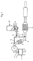
- Fig. 1 shows a diesel engine 1, the exhaust gases via an exhaust line 2 with integrated exhaust aftertreatment devices, here a pre-oxidation catalyst 3 for NO 2 enrichment of the exhaust gas and an SCR catalyst 4 for the selective catalytic reduction of NO x , are discharged to the atmosphere purified.
- the exhaust gas producer may also be a burner or a gas turbine.
- the reducing agent with ammonia before the exhaust gas flow into the SCR catalytic converter 4.
- This one is inside or outside the exhaust line 2 to produce, can be used as a starting basis either a urea water solution or solid urea.
- an ammonia generator 6 is provided which can be arranged outside (as shown in FIG. 1) or within the exhaust line 2 and receives the urea granules by means of the feed device 7 according to the invention via a pipe 8.
- the thermal conversion of urea produces ammonia and isocyanic acid.
- the latter is then also converted into NH 3 and CO 2 within the ammonia generator 6 in conjunction with water vapor by catalytic hydrolysis.
- a partial exhaust gas flow is used, which is controlled via a outgoing from the exhaust line 2 bypass line 9 by a control element 10 in its amount controlled in the ammonia generator 6 can be fed.
- the ammonia-containing gas mixture present at the outlet of the ammonia generator 6 after the conversion process is fed to the exhaust gas flow upstream of the SCR catalytic converter 4, in the illustrated example according to FIG. 1 via a feed line 11.
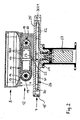
- FIG. 2 shows an exemplary embodiment of the feed device 7 arranged schematically in FIG. 1 in an exemplary assignment to the storage container 5 for the urea granules and to a metering device 12.
- the reservoir 5 has in its lower region inclined surfaces or a funnel 13, which leads to a bottom-side outlet opening 14.
- Their shape and size can be designed either for a single outlet of each of a urea granules or a simultaneous outlet of several urea granules and in the latter case, for example, be formed by an elongated outlet shaft.
- the storage container 5 are arranged above the supply device 7 and the metering device 12 between the storage container 5 and the housing 15 of the supply device.
- the inlet 16 of the metering device 12 is connected to the outlet opening 14 of the reservoir 5 and adapted to the nature and size.
- an endlessly circulating conveyor belt 17 is moved past, which has a plurality of mutually adjacent recesses 17/1, in which in each case a urea granulate grain is receivable.
- the endless conveyor belt 17 may be guided in the housing 18 of the metering device 12 via two toothed wheels 19, 20 mounted at a distance therefrom or via a toothed wheel in conjunction with a slide or deflection device or via two friction wheels or pulleys.
- at least one (s) of the gears 19, 20, friction wheels or pulleys is driven by a motor 21.
- This outlet 22 of the metering device 12 preferably has a curved deflecting device 23, with which the urea granules are largely discharged shock-free from the metering device 12 and can be fed via a subsequent inlet channel 24 of the feed device 7 in this.
- This inlet channel 24 is formed in the cover 25 of the housing 15 of the feeding device via a disc 26 rotatably mounted therein adjacent to its axis of rotation.
- the driven by a motor 27 disc 26 comprises at least one spiral-shaped acceleration channel 28, 29.
- the feed device 7 has an outwardly leading outlet channel 30, to which the ammonia generator 6 leading pipe 8 connects.
- the illustrated exemplary embodiment of the feed device 7 has a disk 26 with two acceleration channels 28, 29 arranged on its upper side. Each of them is bounded on its accelerating side by a wall 31, 32 which has a course formed by a plurality of circular radii and / or a logarithmic curve and / or a curve with a continuous positive gradient.
- the or each acceleration channel 28, 29 begins in the region of the axis of rotation of the disc 26 and is led out to the peripheral edge of the disc 26 and extends there at least approximately tangentially with respect to this.
- annular channel 30/1 coaxial with the axis of rotation of the disc is arranged around the disc 26 at the level of its acceleration channels 28, 29, forming a part of the outlet channel 30 and into which the accelerated urea granules can be introduced via an inlet opening 30/2 are.
- annular channel 30/1 branches off as a further portion of the outlet channel 30 also formed in a housing 15 bore 30/3 tangentially, at which the ammonia generator 6 leading pipe 8 connects.
- the motor 27, from which the disc 26 is driven, is operated separately and independently of the conveyor belt 17 of the metering device 12 driving motor 21.
- the speed at which the urea granules are injected into the ammonia generator 6, and the amount of urea granules to be shot can be set and controlled independently of each other.
- the tube 8 is preferably equipped with a shut-off valve 33. This prevents in the shut-off state that from the ammonia generator 6 heat, solid exhaust gas constituents, moisture and the like can penetrate into the tube 8 and through this to the feed device 7. In addition, the shut-off device 33 prevents the formation of condensation in the pipe 8 and the feeding device 7.
Description
Die Erfindung betrifft eine Zuführvorrichtung zum Zuführen von festen Harnstoffgranulatkörnern in einen innerhalb oder außerhalb einer Abgasleitung angeordneten Ammoniakgenerator mit Merkmalen gemäß dem Oberbegriff des Anspruchs 1.The invention relates to a feeding device for feeding solid urea granules into an ammonia generator arranged inside or outside an exhaust pipe with features according to the preamble of claim 1.
Es ist bekannt, die Abgase von Dieselmotoren mittels selektiver katalytischer Reduktion (SCR) zur NOx-Verminderung zu behandeln. Als Reduktionsmittel für diesen Reinigungsprozesses wird Ammoniak verwendet, der auf verschiedene Art und Weise innerhalb oder außerhalb einer Abgasleitung erzeugbar ist. Ausgangsmaterial hierfür kann fester Harnstoff oder eine Harnstoffwasserlösung sein.It is known to treat the exhaust gases of diesel engines by selective catalytic reduction (SCR) for NO x reduction. As a reducing agent for this cleaning process ammonia is used, which can be generated in various ways inside or outside an exhaust pipe. Starting material for this may be solid urea or a urea water solution.
Eine Zuführvorrichtung zum Zuführen von festen Harnstoffgranulatkörner in einen außerhalb einer Abgasleitung angeordneten Ammoniakgenerator ist der
Die
Aus der
Bei einer ähnlichen, aus der
Obschon bei dieser Lösung keine eigenständige Druckluftquelle notwendig ist, kann sie nicht voll befriedigen, denn sie lässt nur eine relativ grobe Dosierung der Harnstoffprills zu.Although no independent source of compressed air is necessary with this solution, it can not fully satisfy, because it allows only a relatively rough dosage of urea prills.
Es ist demgegenüber Aufgabe der Erfindung, eine Zuführvorrichtung für feste Harnstoffgranulatkörner zu schaffen, bei der auf eine druckluftgestützte Transportierung der Harnstoffgranulatkörner verzichtet werden kann und die eine an den Ammoniakbedarf anpassbare Dosierung der Harnstoffgranulatkörner ermöglicht.It is accordingly an object of the invention to provide a feeding device for solid urea granules, in which it is possible to dispense with a compressed-air-supported transport of the urea granules and which enables a dosage of the urea granules which can be adapted to the ammonia requirement.
Diese Aufgabe ist erfindungsgemäß durch eine Zuführvorrichtung mit den im Anspruch 1 angegebenen Merkmalen gelöst.This object is achieved by a feeding device with the features specified in claim 1.
Vorteilhafte Ausgestaltungen und Weiterbildungen der Erfindung sind in den abhängigen Ansprüchen gekennzeichnet.Advantageous embodiments and further developments of the invention are characterized in the dependent claims.
Kern der erfindungsgemäßen Zuführvorrichtung ist eine in deren Gehäuse angeordnete, angetriebene rotierende Scheibe mit mindestens einem spiralförmig ausgebildeten Beschleunigungskanal, mit dem die einzeln eingeleiteten Harnstoffgranulatkörner auf eine einstellbar hohe Geschwindigkeit beschleunigbar und solchermaßen beschleunigt dem Ammoniakgenerator zuführbar sind.The core of the feeding device according to the invention is arranged in the housing, driven rotating disc with at least one spiral-shaped acceleration channel, with which the individually introduced urea granules can be accelerated to an adjustable high speed and thus accelerated fed to the ammonia generator.
Aufgrund dieser mechanischen Beschleunigung der Harnstoffgranulatkörner ist keine eigenständige Druckluftquelle wie in einigen Fällen des Standes der Technik nötig. Außerdem lässt die erfindungsgemäße Zuführvorrichtung eine sehr exakte anzahl- oder mengenmäßige Dosierung von Harnstoffgranulatkörner zu, was regelungs- und steuerungstechnisch eine genaue Anpassung der erforderlichen Harnstoffmenge an die zur Abgasreinigung notwendige Ammoniakmenge ermöglicht.Due to this mechanical acceleration of the urea granules, no independent compressed air source is required as in some cases of the prior art. In addition, the feed device according to the invention allows for a very exact number or quantitative dosage of urea granules, which allows control technology and control accurate adjustment of the required amount of urea to the amount of ammonia necessary for exhaust gas purification.
Das Harnstoffgranulat besteht vorzugsweise aus kugelförmigen Körnern gleicher Größe. Alternativ hierzu können auch zylinderförmige Harnstoffpellets zur Anwendung kommen. Die Harnstoffgranulatkörner können eine Größe bzw. einen Durchmesser von einigen Zehntel Millimetern bis mehreren Millimetern, vorzugsweise 1,5-3 mm haben und mit einer Dichte von beispielsweise 1,33 g/ml vorkonfektioniert sein.The urea granules preferably consist of spherical grains of the same size. Alternatively, cylindrical urea pellets may also be used. The urea granules may have a size or a diameter of a few tenths of a millimeter to several millimeters, preferably 1.5-3 mm and be pre-assembled with a density of, for example, 1.33 g / ml.
Abhängig von der ihnen aufgeprägten Geschwindigkeit und der Größe der Harnstoffgranulatkörner können diese im Ammoniakgenerator beim Auftreffen auf ein Gitter oder eine Prallfläche oder einen Prallkörper mit unterschiedlichen Flächenwinkeln mehr oder weniger stark in Einzelteile zertrümmert werden. Diesel Harnstoff-Trümmerpartikel weisen im Vergleich zu den in den Ammoniakgenerator eingeschossenen Harnstoffgranulatkörnern in Summe eine wesentlich größere Oberfläche auf und bilden eine Harnstoffpartikelwolke mit günstiger Verteilung eingangs des Hydrolysekatalysators, sodass in letzterem die Umsetzung in Ammoniak optimal und auch bei reduzierten Temperaturen von ca. 150°C-200°C ablaufen kann. Die festen Harnstoffgranulatkörner können mittels der erfindungsgemäßen Zuführvorrichtung so beschleunigt werden, dass sie beim Einschießen in den Ammoniakgenerator eine Geschwindigkeit von vorzugsweise 30-100 m/s aufweisen. Die Rotationsgeschwindigkeit der Scheibe der erfindungsgemäßen Zuführvorrichtung kann z. B. 16.000 Umdrehungen pro Minute betragen. Die Menge der zugeführten Harnstoffgranulatkörner hängt vom NOx-Gehalt des zu reinigenden Abgasstromes ab. So können beispielsweise 100 Harnstoffgranulatkörner pro Sekunde in den Ammoniakgenerator eingeschossen werden. Durch den hohen Förderfrequenzbereich von 20 bis 100 Hertz ist eine optimal einfache Anpassung der Mengenströme an die jeweilige Dosieraufgabe (z. B. in einem Personenkraftwagen oder Nutzfahrzeug) bei vorgegebener Harnstoffgranulatkorngröße möglich.Depending on the speed imposed on them and the size of the urea granules, they can be smashed more or less strongly into individual parts in the ammonia generator when hitting a grid or a baffle or a baffle with different surface angles. Diesel urea debris particles have in total one compared to the urea granules shot into the ammonia generator significantly larger surface area and form a urea particle cloud with favorable distribution of the beginning of the hydrolysis, so that in the latter the reaction in ammonia can proceed optimally and also at reduced temperatures of about 150 ° C-200 ° C. The solid urea granules can be accelerated by means of the feed device according to the invention so that they have a speed of preferably 30-100 m / s when shooting into the ammonia generator. The rotational speed of the disc of the feeding device according to the invention can, for. B. 16,000 revolutions per minute. The amount of urea granules supplied depends on the NO x content of the exhaust gas stream to be cleaned. For example, 100 urea granules per second can be injected into the ammonia generator. Due to the high delivery frequency range of 20 to 100 hertz, optimally simple adaptation of the flow rates to the respective metering task (eg in a passenger car or commercial vehicle) is possible for a given urea granule size.
Durch die Art der Krümmung des wenigstens einen Beschleunigungskanals wird zusätzlich zur Drehzahl der Scheibe die Geschwindigkeit der Harnstoffgranulatkörner beeinflusst. Der wenigstens eine Beschleunigungskanal ist hierzu an seiner Beschleunigungsseite durch eine Wand begrenzt, die einen aus mehreren Kreisradien und/oder einer logarithmischen Kurve und/oder einer Kurve mit durchgehend positiver Steigung gebildeten Verlauf hat.Due to the nature of the curvature of the at least one acceleration channel, the speed of the urea granules is influenced in addition to the rotational speed of the disc. For this purpose, the at least one acceleration channel is delimited on its acceleration side by a wall which has a course formed from a plurality of circular radii and / or a logarithmic curve and / or a curve with a continuously positive gradient.
Vorzugsweise beginnt der mindestens eine an der Oberseite der Scheibe gegebene Beschleunigungskanal im Bereich der Rotationsachse der Scheibe, ist bis zu deren umfänglichem Rand herausgeführt und verläuft dort zumindest annähernd tangential in Bezug auf diesen. Somit wird die gesamte Scheibenfläche optimal ausgenutzt und ein möglichst langer Beschleunigungskanal gebildet, mit dem die Harnstoffgranulatkörner schockfrei von annähernd Null auf eine Maximalgeschwindigkeit beschleunigbar sind. Im Gehäuse der Zuführvorrichtung ist an die rotierende Scheibe in Höhe des mindestens einen an dieser gegebenen Beschleunigungskanals ein zur Rotationsachse koaxialer Ringkanal angeordnet, der einen Teilabschnitt des Auslasskanals bildet und in den die beschleunigten Harnstoffgranulatkörner über eine Einlassöffnung einleitbar sind.Preferably, the at least one accelerating channel provided on the upper side of the disk begins in the region of the axis of rotation of the disk, is led out to its peripheral edge and extends there at least approximately tangentially with respect to it. Thus, the entire disk surface is optimally utilized and formed as long as possible acceleration channel with which the urea granules are accelerated shock-free from approximately zero to a maximum speed. In the housing of the feeding device, an annular channel coaxial with the axis of rotation is arranged on the rotating disk at the level of the at least one acceleration channel provided, which forms a partial section of the outlet channel and into which the accelerated urea granules can be introduced via an inlet opening.
Durch den randseitig tangentialen Auslauf des wenigstens einen Beschleunigungskanals können die Harnstoffgranulatkörner mit maximaler Geschwindigkeit ohne Energieverluste von der Scheibe in die sie umgebende Nut eingeleitet und aus dieser über eine, einen weiteren Abschnitt des Auslasskanals bildende, tangential abzweigende Bohrung in das sich daran anschließende Rohr eingeleitet und über dieses in den Ammoniakgenerator eingeschossen werden.Due to the edge-side tangential outlet of the at least one acceleration channel, the urea granules can be introduced at maximum speed without energy losses from the disk into the groove surrounding it and from this via one, another Section of the outlet channel forming, tangentially branching bore introduced into the adjoining tube and injected through this into the ammonia generator.
Der Zuführvorrichtung ist in bevorzugter Weise eine Dosiereinrichtung zugeordnet, mit der die Harnstoffgranulatkörner aus dem Vorratsbehälter dosiert in das Gehäuse der Zuführvorrichtung einleitbar sind. Der Vorratsbehälter ist vorzugsweise oberhalb des Gehäuses und der rotierenden Scheibe angeordnet und weist in seinem unteren Bereich wenigstens eine schräge, zu einer bodenseitigen Auslassöffnung hinführende Fläche auf. Letzteres stellt sicher, dass die Harnstoffgranulatkörner ohne zusätzliche Fördermittel und -maßnahmen allein durch die Schwerkraft aus dem Vorratsbehälter ausgeleitet werden.The feed device is preferably associated with a metering device, with which the urea granules from the reservoir metered into the housing of the feeder can be introduced. The storage container is preferably arranged above the housing and the rotating disk and has in its lower region at least one inclined surface which leads to a bottom-side outlet opening. The latter ensures that the urea granules are discharged out of the reservoir solely by gravity without additional funding and measures.
Die Dosiereinrichtung ist zwischen dem Vorratsbehälter für die Harnstoffgranulatkörner und dem Gehäuse der Zuführvorrichtung angeordnet. Der Einlass der Dosiereinrichtung ist mit der Auslassöffnung des Vorratsbehälters und der Auslass der Dosiereinrichtung ist mit dem Einlass der Zuführvorrichtung verbunden.The metering device is arranged between the storage container for the urea granules and the housing of the feed device. The inlet of the metering device is connected to the outlet opening of the reservoir and the outlet of the metering device is connected to the inlet of the supply device.
Die bodenseitige Auslassöffnung im Vorratsbehälter kann hinsichtlich ihrer Form und Größe entweder auf einen Einzelauslass der Harnstoffgranulatkörner oder einen gleichzeitigen Auslass mehrerer Harnstoffgranulatkörner ausgelegt sein. In letzterem Fall kann die Auslassöffnung durch einen länglichen Auslassschacht gebildet sein.The bottom-side outlet opening in the reservoir can be designed in terms of their shape and size either on a single outlet of the urea granules or a simultaneous outlet of several urea granules. In the latter case, the outlet opening may be formed by an elongated outlet shaft.
Der Einlass der Dosiereinrichtung ist wiederum an die Art und Größe der Auslassöffnung des Vorratsbehälters angepasst.The inlet of the metering device is in turn adapted to the type and size of the outlet opening of the reservoir.
Die Dosiereinrichtung weist beispielsweise ein endlos umlaufendes Förderband mit einer Vielzahl von aneinander angrenzenden Vertiefungen auf, in denen jeweils ein Harnstoffgranulatkorn aufnehmbar ist. Das Förderband der Dosiereinrichtung ist über zwei voneinander beabstandete Zahnräder oder über ein Zahnrad in Verbindung mit einer Kulisse oder Umlenkeinrichtung oder über zwei voneinander beabstandete Reibräder oder Riemenscheiben geführt, wobei wenigstens eines der Zahnräder, Reibräder oder eine der Riemenscheiben durch einen Motor angetrieben ist. Dabei ist der Antrieb des Förderbandes der Dosiereinrichtung vorzugsweise unabhängig vom Antrieb der Scheibe der Zuführvorrichtung. Auf diese Weise kann der rotierenden Scheibe der Zuführvorrichtung durch die Dosiereinrichtung die Menge der Harnstoffgranulatkörner sehr präzise zudosiert werden. Dabei orientiert sich diese Zudosierung am Verunreinigungsgrad, insbesondere am Stickoxidgehalt des Abgases und der hierdurch bedingten Menge an Ammoniak für eine diesbezüglich katalytische Stickoxidreduzierung.The metering device has, for example, an endlessly circulating conveyor belt with a plurality of adjoining depressions, in each of which a urea granulate grain can be received. The conveyor belt of the metering device is guided via two gear wheels spaced apart from one another or via a gearwheel in connection with a guide or deflection device or via two spaced-apart friction wheels or pulleys, wherein at least one of the gearwheels, friction wheels or one of the belt pulleys is driven by a motor. The drive of the conveyor belt of the metering device is preferably independent of the drive of the disc of the feeder. In this way, the amount of urea granules can be metered into the rotating disk of the feeder by the metering device very precisely. This is based on this Metering at the level of impurity, in particular the nitrogen oxide content of the exhaust gas and the amount of ammonia caused thereby for a catalytic nitrogen oxide reduction in this regard.
Im Detail ist es möglich, im Auslass der Dosiereinrichtung beispielsweise eine Umlenkeinrichtung vorzusehen, mit der die Harnstoffgranulatkörner ausgangs der Dosiereinrichtung in Richtung des Einlasses der Zuführvorrichtung und deren rotierender Scheibe hin umlenkbar sind. An den Auslass der Dosiervorrichtung schließt sich dann nach der Umlenkvorrichtung der Einlasskanal der Zuführvorrichtung an, der im Deckel von deren Gehäuse über der rotierenden Scheibe benachbart zu deren Rotationsachse ausgebildet ist.In detail, it is possible, for example, to provide a deflection device in the outlet of the metering device with which the urea granules can be deflected outwards of the metering device in the direction of the inlet of the feed device and its rotating disk. At the outlet of the metering then adjoins the deflection of the inlet channel of the feeder, which is formed in the lid of the housing over the rotating disk adjacent to its axis of rotation.
In bevorzugter Weise ist die Zuführvorrichtung mittels eines Sperrventils gegenüber Gasen, Schmutz, Feuchtigkeit, festen Abgasrückständen etc. gasdicht absperrbar, der bzw. die über das Rohr vom Ammoniakgenerator oder der Abgasleitung her zu ihr vordringen könnten.Preferably, the supply device by means of a check valve against gases, dirt, moisture, solid exhaust gas residues, etc., gas-tight shut off, or could penetrate through the pipe from the ammonia generator or the exhaust pipe forth to her.
Nachfolgend ist die erfindungsgemäße Vorrichtung anhand der Zeichnung noch näher erläutert. In der Zeichnung zeigen:
- Fig. 1
- schematisch den Abgasstrang eines Dieselmotors mit Abgasnachbehandlungsvorrichtungen und einer Art der Zuordnung der erfindungsgemäßen Vorrichtung,
- Fig. 2
- im Schnitt eine Ausführungsform der erfindungsgemäßen Zuführvorrichtung mit zugeordnetem Vorratsbehälter für die Harnstoffgranulatkörner und zugeordneter Dosiervorrichtung,
- Fig. 3
- eine perspektivische Ansicht auf ein Ausführungsbeispiel der erfindungsgemäßen Zuführvorrichtung bei offenem Gehäuse auf die rotierende Scheibe.
- Fig. 1
- 1 schematically shows the exhaust gas line of a diesel engine with exhaust gas aftertreatment devices and a way of assigning the device according to the invention,
- Fig. 2
- in section an embodiment of the feeding device according to the invention with associated reservoir for the urea granules and associated metering device,
- Fig. 3
- a perspective view of an embodiment of the feed device according to the invention with the housing open on the rotating disk.
Fig. 1 zeigt einen Dieselmotor 1, dessen Abgase über einen Abgasstrang 2 mit integrierten Abgasnachbehandlungsvorrichtungen, hier einem Voroxidationskatalysator 3 zur NO2-Anreicherung des Abgases und einem SCR-Katalysator 4 zur selektiven katalytischen Reduktion von NOx, gereinigt an die Atmosphäre abgeführt werden. Anstelle des Dieselmotors 1 kann der Abgasproduzent auch ein Brenner oder eine Gasturbine sein. Um die NOx-Reduktion im SCR-Katalysator herbeizuführen ist es notwendig, dem Abgasstrom vor dem Eintritt in den SCR-Katalysator 4 das Reduktionsmittel Ammoniak beizumischen. Dieser ist innerhalb oder außerhalb des Abgasstranges 2 zu erzeugen, wobei als Ausgangsbasis entweder eine Harnstoffwasserlösung oder fester Harnstoff zur Anwendung kommen kann.Fig. 1 shows a diesel engine 1, the exhaust gases via an
Im vorliegenden Fall interessiert nur der feste Harnstoff, der in Form vorkonfektionierter kugelförmiger oder zylindrischer Granulatkörner in einem nachfüllbaren Vorratsbehälter 5 bevorratbar und aus diesem für die Ammoniakerzeugung abgebbar ist. Zur Ammoniakerzeugung ist ein Ammoniakgenerator 6 vorgesehen, der außerhalb (wie in Fig. 1 dargestellt) oder innerhalb des Abgasstrangs 2 angeordnet sein kann und die Harnstoffgranulatkörner mittels der erfindungsgemäßen Zuführvorrichtung 7 über ein Rohr 8 zugeführt bekommt. Bei der thermischen Umsetzung des Harnstoffs entstehen Ammoniak und Isocyansäure. Letztere wird anschließend innerhalb des Ammoniakgenerators 6 in Verbindung mit Wasserdampf durch katalytische Hydrolyse ebenfalls in NH3 und CO2 umgewandelt. Als Wasserdampfquelle ist im Beispiel von Fig. 1 ein Abgasteilstrom herangezogen, der über eine vom Abgasstrang 2 abgehende Bypassleitung 9 durch ein Regelorgan 10 in seiner Menge geregelt in den Ammoniakgenerator 6 einspeisbar ist. Das nach dem Umwandlungsprozess am Ausgang des Ammoniakgenerators 6 gegebene, Ammoniak enthaltende Gasgemisch wird strömungsmäßig vor dem SCR-Katalysator 4 in den Abgasstrom eingespeist, im dargestellten Beispiel gemäß Fig. 1 über eine Speiseleitung 11.In the present case, only the solid urea, which can be stored in the form of prefabricated spherical or cylindrical granules in a
Fig. 2 zeigt ein Ausführungsbeispiel der in Fig. 1 schematisch angeordneten Zuführvorrichtung 7 in einer beispielhaften Zuordnung zum Vorratsbehälter 5 für die Harnstoffgranulatkörner und zu einer Dosiereinrichtung 12.FIG. 2 shows an exemplary embodiment of the
Der Vorratsbehälter 5 weist in seinem unteren Bereich schräge Flächen oder einen Trichter 13 auf, die bzw. der zu einer bodenseitigen Auslassöffnung 14 hinführt. Deren Form und Größe kann entweder auf einen Einzelauslass jeweils eines Harnstoffgranulatkorns oder auf einen gleichzeitigen Auslass mehrerer Harnstoffgranulatkörner ausgelegt und in letzterem Fall beispielsweise durch einen länglichen Auslassschacht gebildet sein.The
Im dargestellten Beispiel sind der Vorratsbehälter 5 oberhalb der Zuführvorrichtung 7 und die Dosiereinrichtung 12 zwischen dem Vorratsbehälter 5 und dem Gehäuse 15 der Zuführvorrichtung angeordnet. Der Einlass 16 der Dosiereinrichtung 12 ist mit der Auslassöffnung 14 des Vorratsbehälters 5 verbunden und an deren Art und Größe angepasst. Unterhalb des Einlasses 16 der Dosiereinrichtung 12 wird ein endlos umlaufendes Förderband 17 vorbeibewegt, das eine Vielzahl von aneinander angrenzenden Vertiefungen 17/1 aufweist, in denen jeweils ein Harnstoffgranulatkorn aufnehmbar ist. Das endlose Förderband 17 kann im Gehäuse 18 der Dosiereinrichtung 12 über zwei dort voneinander beabstandet gelagerte Zahnräder 19, 20 oder über ein Zahnrad in Verbindung mit einer Kulisse oder Umlenkeinrichtung oder über zwei Reibräder oder Riemenscheiben geführt sein. Dabei ist mindestens eine(s) der Zahnräder 19, 20, Reibräder oder Riemenscheiben durch einen Motor 21 angetrieben.In the illustrated example, the
Die über die schrägen Flächen bzw. den Trichter 13 zur Auslassöffnung 14 im Vorratsbehälter 5 hinrutschenden Harnstoffgranulatkörner fallen über die Auslassöffnung 14 und den Einlass 16 der Dosiereinrichtung in die Vertiefungen 18 des Förderbandes 17 und werden mittels diesen zu einem Auslass 22 transportiert. Dieser Auslass 22 der Dosiereinrichtung 12 weist bevorzugt eine gekrümmte Umlenkvorrichtung 23 auf, mit der die Harnstoffgranulatkörner weitestgehend schockfrei aus der Dosiereinrichtung 12 ausgeleitet und über einen anschließenden Einlasskanal 24 der Zuführvorrichtung 7 in diese einspeisbar sind. Dieser Einlasskanal 24 ist im Deckel 25 des Gehäuses 15 der Zuführvorrichtung über einer darin rotierend gelagerten Scheibe 26 benachbart zu deren Rotationsachse ausgebildet.The urea granules sliding over the inclined surfaces or the
Die durch einen Motor 27 angetriebene Scheibe 26 weist erfindungsgemäß wenigstens einen spiralförmig ausgebildeten Beschleunigungskanal 28, 29 auf. Darüber hinaus weist die Zuführvorrichtung 7 einen nach außen führenden Auslasskanal 30 auf, an den sich das zum Ammoniakgenerator 6 hinführende Rohr 8 anschließt.The driven by a
Wie gut aus Fig. 3 ersichtlich, weist das dargestellte Ausführungsbeispiel der Zuführvorrichtung 7 eine Scheibe 26 mit zwei an ihrer Oberseite angeordneten Beschleunigungskanälen 28, 29 auf. Jeder derselben ist an seiner Beschleunigungsseite durch eine Wand 31, 32 begrenzt, die einen aus mehreren Kreisradien und/oder einer logarithmischen Kurve und/oder einer Kurve mit durchgehend positiver Steigung gebildeten Verlauf hat. Dabei beginnt der bzw. jeder Beschleunigungskanal 28, 29 im Bereich der Rotationsachse der Scheibe 26 und ist bis zum umfänglichen Rand der Scheibe 26 herausgeführt und verläuft dort zumindest annähernd tangential in Bezug auf diesen. Durch die Rotation der Scheibe 26 mit den spiralförmig ausgebildeten Beschleunigungskanälen 28, 29 wird jedes zugeführte Harnstoffgranulatkorn von der Mitte der Scheibe 26 bis zu deren Rand auf eine maximale, sehr hohe Geschwindigkeit beschleunigt.As can readily be seen from FIG. 3, the illustrated exemplary embodiment of the
Im Gehäuse 15 der Zuführvorrichtung ist um die Scheibe 26 in Höhe von deren Beschleunigungskanälen 28, 29 ein zur Rotationsachse der Scheibe koaxialer Ringkanal 30/1 angeordnet, der einen Teil des Auslasskanals 30 bildet und in den die beschleunigten Harnstoffgranulatkörner über eine Einlassöffnung 30/2 einleitbar sind. Von diesem Ringkanal 30/1 zweigt als weiterer Abschnitt des Auslasskanals 30 eine ebenfalls in Gehäuse 15 ausgebildete Bohrung 30/3 tangential ab, an der sich das zum Ammoniakgenerator 6 führende Rohr 8 anschließt. Durch diese tangentiale Anordnung der Bohrung 30/3 und deren geradlinige Fortführung durch das Rohr 8 können daher die beschleunigten Harnstoffgranulatkörner aus dem Ringkanal 30/1 mit maximaler Geschwindigkeit in Richtung Ammoniakgenerator 6 befördert werden.In the
Der Motor 27, von dem die Scheibe 26 angetrieben ist, wird separat und unabhängig zu dem das Förderband 17 der Dosiereinrichtung 12 antreibenden Motors 21 betrieben.The
Durch diesen separaten Antrieb des Förderbandes 17 und der Scheibe 26 können die Geschwindigkeit, mit der die Harnstoffgranulatkörner in den Ammoniakgenerator 6 eingeschossen werden, und die Menge der einzuschießenden Harnstoffgranulatkörner unabhängig voneinander eingestellt und geregelt werden.By this separate drive of the
Das Rohr 8 ist vorzugsweise mit einem Absperrventil 33 ausgerüstet. Dieses verhindert im Absperrzustand, dass aus dem Ammoniakgenerator 6 Wärme, feste Abgasbestandteile, Feuchtigkeit und dergleichen in das Rohr 8 und über dieses zur Zuführvorrichtung 7 eindringen können. Außerdem verhindert die Absperrvorrichtung 33 die Bildung von Kondenswasser im Rohr 8 und der Zuführvorrichtung 7.The
- 11
- Dieselmotordiesel engine
- 22
- Abgasstrangexhaust gas line
- 33
- Voroxidationskatalysatorpre-oxidation catalyst
- 44
- SCR-KatalysatorSCR catalyst
- 55
- Vorratsbehälterreservoir
- 66
- Ammoniakgeneratorammonia generator
- 77
- Zuführvorrichtungfeeder
- 88th
- Rohr zw. 7 und 6Pipe between 7 and 6
- 99
- Bypassleitungbypass line
- 1010
- Regelorganregulating element
- 1111
- Speiseleitungfeeder
- 1212
- Dosiereinrichtungmetering
- 1313
- Flächen/Trichter in 5Surfaces / funnels in 5
- 1414
- Auslassöffnung von 5Outlet opening of 5
- 1515
- Gehäuse von 7Housing of 7
- 1616
- Einlass von 12Admission of 12
- 1717
- Förderband in 12Conveyor belt in 12th
- 1818
- Gehäuse von 12Housing of 12
- 1919
- Zahnrad in 12Gear in 12th
- 2020
- Zahnrad in 12Gear in 12th
- 2121
- Motor von 12Engine of 12
- 2222
- Auslass von 12Outlet of 12
- 2323
- Umlenkvorrichtung in 22Deflection device in 22
- 2424
- Einlasskanalinlet channel
- 2525
- Deckel an 15Cover at 15
- 2626
- Scheibe in 7Disc in 7
- 2727
- Motor von 7Engine of 7
- 2828
- Beschleunigungskanal an 26Acceleration channel on 26
- 2929
- Beschleunigungskanal an 26Acceleration channel on 26
- 3030
- Auslasskanalexhaust port
- 30/11.30
- Ringkanalannular channel
- 30/22.30
- Einlassöffnung für 30/1Inlet opening for 30/1
- 30/33.30
- Bohrung von 30Bore of 30
- 3131
- Wand an 28Wall at 28
- 3232
- Wand an 29Wall at 29
- 3333
- Absperrventilshut-off valve
Claims (17)
- A feed apparatus (7) for feeding solid urea granules into an ammonia generator (6) arranged inside or outside an exhaust-gas line in order to produce ammonia, which ammonia generator (6), during the catalytic cleaning of the exhaust gas of an internal-combustion engine, gas turbine or burner, carries out the NOx reduction, wherein the urea granules are stored in a storage container (5), characterized in that the feed apparatus (7) has a housing (15) with an inlet (24) for feeding in the urea granules and, on the inside, a rotating disc (26) driven by a motor and having at least one acceleration duct (28, 29) in the shape of a spiral and an outlet duct (30) which leads to the outside and to which a pipe (8) leading to the ammonia generator (6) is connected.
- A feed apparatus according to Claim 1, characterized in that the at least one spiral acceleration duct (28, 29) is arranged on the upper side of the disc (26) and is bounded on its acceleration side by a wall (31, 32) which has a shape formed from a plurality of radii of a circle and/or a logarithmic curve and/or a curve with a continuously positive gradient.
- A feed apparatus according to one of Claims 1 and 2, characterized in that the at least one acceleration duct (28, 29) starts in the region of the axis of rotation of the disc (26), continues as far as the peripheral edge of the disc (26) and there extends at least substantially tangentially with respect to the said peripheral edge.
- A feed apparatus according to any one of Claims 1 to 3, characterized in that an annular duct (30), which is coaxial with the axis of rotation and which forms a portion of the outlet duct (30) and into which the accelerated urea granules are capable of being introduced by way of an inlet opening (30/2), is provided in the housing (15) around the disc (26) at the level of the at least one acceleration duct (28, 29) provided on it.
- A feed apparatus according to Claim 4, characterized in that a bore (30/3), to which the pipe (8) leading to the ammonia generator (6) is connected, branches tangentially off, as a further portion of the outlet duct (30), from the annular duct (30/1) provided in the housing (15) around the disc (26).
- A feed apparatus according to Claim 1, characterized in that it has associated with it a metering device (12) by which the urea granules are capable of being introduced from the storage container (5) in a metered manner into the housing (15) of the feed apparatus (7).
- A feed apparatus according to any one of Claims 1 to 6, characterized in that the lower region of the storage container (5) arranged above it for the urea granules has a funnel or at least one oblique face (13) leading to an outlet (14) opening at the bottom.
- A feed apparatus according to Claims 6 and 7, characterized in that the metering device (12) is arranged between the storage container (5) and the housing (15) of the feed apparatus (7), the inlet (16) of the metering device (12) is connected to the outlet opening (14) of the storage container (5), and the outlet (22) of the metering device (12) is connected to the inlet (24) of the feed apparatus (7).
- A feed apparatus according to Claim 8, characterized in that with respect to its shape and size the outlet opening (14) at the bottom in the storage container (5) is designed for the individual discharge of the urea granules.
- A feed apparatus according to Claim 8, characterized in that with respect to its shape and size the outlet opening (14) at the bottom in the storage container (5) is designed for the simultaneous discharge of a plurality of urea granules and is preferably formed by an elongate outlet chute.
- A feed apparatus according to one of Claims 9 and 10, characterized in that the inlet (16) of the metering device (12) is adapted to the nature and size of the outlet opening (14) of the storage container (5).
- A feed apparatus according to any one of Claims 6, 8 and 11, characterized in that the metering device (12) comprises an endlessly circulating conveyor belt (17) running past the inlet (16) and having a plurality of depressions (17/1) adjacent to one another in which one urea granule is capable of being received in each case.
- A feed apparatus according to Claim 12, characterized in that the conveyor belt (17) of the metering device (12) is guided over two toothed wheels (19, 20) arranged at a distance from each other or over one toothed wheel in conjunction with a slide block or a deflecting device or over two friction wheels or belt pulleys, and at least one of the toothed wheels (19, 20), friction wheels or belt pulleys is driven by a motor (21).
- A feed apparatus according to Claim 13, characterized in that the drive of the conveyor belt (17) of the metering device (12) is independent of the drive of the disc (16) of the feed apparatus (7).
- A feed apparatus according to any one of Claims 8, 12 and 13, characterized in that the outlet (22) of the metering device (12) has a deflecting device (23) by which the urea granules are capable of being deflected at the outlet of the metering device (12) in the direction of the inlet (24) of the feed apparatus (7) and towards the rotating disc (26).
- A feed apparatus according to Claim 15, characterized in that the inlet duct (24) of the feed apparatus (7) attached to the outlet (22) of the metering device (12) downstream of the deflecting device (23) is formed in the cover (25) of the housing (15) of the said feed apparatus (7) above the rotating disc (26) and adjacent to the axis of rotation of the latter.
- A feed apparatus according to Claim 1, characterized in that the pipe (8) is provided with a shut-off valve (33) which prevents heat, solid exhaust-gas constituents, moisture and the like from being able to penetrate from the ammonia generator (6) into the pipe (8) and by way of the latter to the feed apparatus (7).
Applications Claiming Priority (2)
| Application Number | Priority Date | Filing Date | Title |
|---|---|---|---|
| DE102004029387 | 2004-06-17 | ||
| DE102004029387A DE102004029387B4 (en) | 2004-06-17 | 2004-06-17 | Feeding device for feeding solid urea prills or pellets to an ammonia generator |
Publications (3)
| Publication Number | Publication Date |
|---|---|
| EP1607372A2 EP1607372A2 (en) | 2005-12-21 |
| EP1607372A3 EP1607372A3 (en) | 2006-07-26 |
| EP1607372B1 true EP1607372B1 (en) | 2007-07-04 |
Family
ID=34993214
Family Applications (1)
| Application Number | Title | Priority Date | Filing Date |
|---|---|---|---|
| EP05009649A Active EP1607372B1 (en) | 2004-06-17 | 2005-05-03 | Device for feeding solid urea prills to an ammoniagenearator aranged inside or outside an exhaust line |
Country Status (4)
| Country | Link |
|---|---|
| US (1) | US7178329B2 (en) |
| EP (1) | EP1607372B1 (en) |
| JP (1) | JP2006002775A (en) |
| DE (2) | DE102004029387B4 (en) |
Families Citing this family (24)
| Publication number | Priority date | Publication date | Assignee | Title |
|---|---|---|---|---|
| DE102004042225B4 (en) * | 2004-09-01 | 2017-08-31 | MAN Truck & Bus Aktiengesellschaft | Apparatus and method for producing ammonia from solid urea pellets |
| DE102005018949A1 (en) * | 2005-04-18 | 2006-10-19 | Ami-Agrolinz Melamine International Gmbh | Solid particles production, especially urea particles, from flowable starting material containing e.g. actinium oxide, useful e.g. in catalysts or milling bodies, comprises splitting into droplets and introducing into solidification liquid |
| DE102006004170A1 (en) * | 2006-01-27 | 2007-08-02 | Pierburg Gmbh | Thermolysis assembly in exhaust pipe upstream of and heated by oxidation catalytic converter reduces automotive nitric oxide emissions |
| DE102006023146A1 (en) * | 2006-05-16 | 2007-11-22 | Emitec Gesellschaft Für Emissionstechnologie Mbh | Method and device for providing a gaseous substance mixture |
| DE102006023145A1 (en) * | 2006-05-16 | 2007-11-22 | Emitec Gesellschaft Für Emissionstechnologie Mbh | Method and device for the treatment of the exhaust gas of an internal combustion engine |
| DE102006032292A1 (en) * | 2006-07-11 | 2008-01-24 | Volkswagen Ag | Reducing agent treatment system for SCR catalysts |
| DE102006034204B4 (en) * | 2006-07-25 | 2008-04-17 | Pierburg Gmbh | metering |
| DE102006047019A1 (en) * | 2006-10-02 | 2008-04-03 | Emitec Gesellschaft Für Emissionstechnologie Mbh | Exhaust gas system's reduction agent containing gas flow providing method for internal combustion engine, involves adding reduction agent containing gas flow to exhaust gas of internal combustion engine |
| WO2008078059A1 (en) * | 2006-12-22 | 2008-07-03 | Perkins Engines Company Ltd | Method and apparatus for selective catalytic nox reduction |
| DE102006062026B4 (en) * | 2006-12-29 | 2009-08-20 | Pierburg Gmbh | Dosing device for solid urea particles |
| US8069655B2 (en) * | 2007-08-13 | 2011-12-06 | Cummins Filtration Ip, Inc. | Apparatus, system, and method for using a fraction of engine exhaust to deliver a dosant |
| US8056671B2 (en) * | 2007-10-12 | 2011-11-15 | Mazda Motor Corporation | Exhaust-gas purification device disposition structure of vehicle |
| DE102008005759A1 (en) | 2008-01-24 | 2009-07-30 | Volkswagen Ag | Storage vessel for storage of hygroscopic solid provided in division level, has partial volume of interior space of storage vessel, where solid is stored |
| DE102008048209A1 (en) | 2008-09-20 | 2010-04-01 | Volkswagen Ag | Method for operating exhaust-gas cleaning system to perform catalytic removal of nitrogen oxide from exhaust gas of motor vehicle, involves supplying reducing agent, and rinsing storage tank with preset volume of non-lubricated air |
| DE102010029340A1 (en) * | 2010-05-27 | 2011-12-01 | Robert Bosch Gmbh | Method for operating selective catalytic reduction catalyst that is arranged in exhaust line of combustion engine, involves dosing liquid reducing agent solution through metering values that are controlled by predetermined dosing pattern |
| US9371240B2 (en) * | 2011-07-01 | 2016-06-21 | Alzchem Ag | Ammonia gas generator for producing ammonia in order to reduce nitrogen oxides in exhaust gases |
| WO2013082078A1 (en) | 2011-12-02 | 2013-06-06 | Cummins Inc. | Solid storage media charging with ammonia for use in selective catalytic reduction |
| CN102943703A (en) * | 2012-12-07 | 2013-02-27 | 吉林大学 | Device for quantitatively generating ammonia from solid urea |
| CN104003416B (en) * | 2013-04-19 | 2015-09-30 | 中国大唐集团环境技术有限公司 | A kind of volute air-inlet whirlwind-type urea pyrolysis ammonia-preparing device and method |
| CN103287871A (en) * | 2013-05-22 | 2013-09-11 | 南通三鑫重工机械有限公司 | Silo-side unloading device |
| CN105626215A (en) * | 2014-10-27 | 2016-06-01 | 金有纯 | Device for regulating and controlling actual supply amount of urea entering exhaust system and regulating and controlling method |
| GB2591678B (en) * | 2018-10-02 | 2022-11-23 | Cummins Emission Solutions Inc | Systems and methods for dry chemical reductant insertion in aftertreatment systems |
| CN113464837B (en) * | 2021-09-01 | 2021-11-19 | 江苏新鹏重型机电制造有限公司 | Auxiliary air inlet structure with vortex type pressure stabilizing and flow guiding function for desulfurization and denitrification and method |
| CN114542245B (en) * | 2022-01-24 | 2023-05-02 | 安徽理工大学 | Motor vehicle tail gas degradation treatment equipment |
Family Cites Families (13)
| Publication number | Priority date | Publication date | Assignee | Title |
|---|---|---|---|---|
| DE4423003C2 (en) * | 1993-07-06 | 1999-01-21 | Ford Werke Ag | Method and device for reducing NO¶x¶ in exhaust gases from automotive internal combustion engines |
| JPH081436U (en) * | 1994-11-22 | 1996-10-01 | 株式会社新潟鉄工所 | Exhaust gas reducing agent supply device |
| DE19504992C1 (en) * | 1995-02-15 | 1996-03-14 | Labschies Hartmut | Loose material delivery device with feed rate or dosing quantity measurement |
| US5809775A (en) * | 1997-04-02 | 1998-09-22 | Clean Diesel Technologies, Inc. | Reducing NOx emissions from an engine by selective catalytic reduction utilizing solid reagents |
| US6399034B1 (en) * | 1997-05-14 | 2002-06-04 | Hjs Fahrzeugtechnik Gmbh & Co. | Process for reducing nitrogen oxides on SCR catalyst |
| DE19827678B4 (en) * | 1998-06-22 | 2010-05-20 | Hjs Fahrzeugtechnik Gmbh & Co | Emission control system for removing exhaust gases from combustion units |
| US6266955B1 (en) * | 1999-08-20 | 2001-07-31 | Caterpillar Inc. | Diagnostic system for an emissions control on an engine |
| JP3600509B2 (en) * | 2000-06-23 | 2004-12-15 | トヨタ自動車株式会社 | Exhaust gas purification device for internal combustion engine |
| DE10038741A1 (en) * | 2000-08-09 | 2002-02-21 | Porsche Ag | Introducing reductant into catalytic arrangement involves producing reductant solution from solid reductant and solvent, storing solution in container and feeding to catalytic arrangement |
| DE10206028A1 (en) * | 2002-02-14 | 2003-08-28 | Man Nutzfahrzeuge Ag | Process and apparatus for producing ammonia |
| US20030211024A1 (en) * | 2002-05-10 | 2003-11-13 | Wojichowski David Lee | Methods of converting urea to ammonia for SCR, SNCR and flue gas conditioning |
| DE10251498A1 (en) * | 2002-11-04 | 2004-05-19 | Universität Kaiserslautern | Process and assembly to release urea pellets to automotive exhaust gases at a controlled rate regulated by a rotating disc with compressed air supply |
| DE10252734A1 (en) * | 2002-11-13 | 2004-05-27 | Robert Bosch Gmbh | Purifying I.C. engine exhaust gases involves introducing solid reductant into exhaust gas channel |
-
2004
- 2004-06-17 DE DE102004029387A patent/DE102004029387B4/en active Active
-
2005
- 2005-05-03 EP EP05009649A patent/EP1607372B1/en active Active
- 2005-05-03 DE DE502005000961T patent/DE502005000961D1/en active Active
- 2005-06-16 US US11/155,333 patent/US7178329B2/en active Active
- 2005-06-17 JP JP2005177314A patent/JP2006002775A/en not_active Ceased
Non-Patent Citations (1)
| Title |
|---|
| None * |
Also Published As
| Publication number | Publication date |
|---|---|
| DE102004029387B4 (en) | 2006-12-28 |
| EP1607372A2 (en) | 2005-12-21 |
| US7178329B2 (en) | 2007-02-20 |
| US20050284135A1 (en) | 2005-12-29 |
| JP2006002775A (en) | 2006-01-05 |
| DE502005000961D1 (en) | 2007-08-16 |
| DE102004029387A1 (en) | 2006-01-12 |
| EP1607372A3 (en) | 2006-07-26 |
Similar Documents
| Publication | Publication Date | Title |
|---|---|---|
| EP1607372B1 (en) | Device for feeding solid urea prills to an ammoniagenearator aranged inside or outside an exhaust line | |
| DE102004042225B4 (en) | Apparatus and method for producing ammonia from solid urea pellets | |
| EP3067529B1 (en) | Device for after-treatment of exhaust from a motor vehicle | |
| EP0852512B1 (en) | Method and device for decomposing oxides of nitrogen in the exhaust gases from an internal-combustion engine | |
| EP2090761B1 (en) | Exhaust gas treatment system for an internal combustion engine | |
| DE102007020812B4 (en) | Apparatus and method for the addition of fluid pollutant-reducing media in an exhaust passage of an internal combustion engine | |
| EP1567752B1 (en) | Device and method for dosing and transporting dry urea, especially during the implementation of the scr method in motor vehicles | |
| DE102007047774B4 (en) | Apparatus and method for reducing nitrogen oxides in the exhaust system of an internal combustion engine | |
| EP2229348A2 (en) | Method and drop former for producing tablets and method for producing a sulfurous fertilizer | |
| DE102004045770B3 (en) | Jet drier for surfaces has gas flow generator for carrying drying granules with metering feed for supplying granules into gas flow | |
| DE10247414B4 (en) | Plant for gluing fibers for the production of fiberboard, in particular MDF boards o. The like. Wood-based panels | |
| WO2018149814A1 (en) | Cooling module of a continuous sintering furnace | |
| EP3074181A1 (en) | Method and device for cleaning a jet engine | |
| EP1061265A1 (en) | Turbocharger for a slow speed diesel engine | |
| DE3006438C2 (en) | Process for charging a continuous mixer and continuous mixer | |
| DE368968C (en) | Device for preheating the fuel in the feed container before entering the hammer mill for fuel dust firing | |
| EP0430144A1 (en) | Method and apparatus for reducing the concentration of nitrogen oxides in waste gases of combustion processes | |
| DE19531504B4 (en) | Intake device for combustion air of internal combustion engines with air purification | |
| DE3616310C2 (en) | ||
| DE102005010781A1 (en) | Sand blaster for cleaning different surfaces includes metering device for granules and a control unit with adjustable throttle valve upstream of inlet chamber to adapt gas flow to type of surface being cleaned | |
| EP2879980B1 (en) | Apparatus for accommodating bulk material having a discharge device | |
| DE2461539C2 (en) | Feeding device for feeding granular bulk material into a conveying line | |
| DE2652365A1 (en) | METHOD AND APPARATUS FOR REMOVING POLLUTION FROM A GAS FLOW | |
| EP1882833A1 (en) | Metering device | |
| DE102004031388A1 (en) | Shaped parts deburring system, has cylindrical drum arranged in horizontal manner for receiving shaped parts and control to displace drum to oscillation motion, where drum casing has spinner for loading drum with blasting abrasive |
Legal Events
| Date | Code | Title | Description |
|---|---|---|---|
| PUAI | Public reference made under article 153(3) epc to a published international application that has entered the european phase |
Free format text: ORIGINAL CODE: 0009012 |
|
| AK | Designated contracting states |
Kind code of ref document: A2 Designated state(s): AT BE BG CH CY CZ DE DK EE ES FI FR GB GR HU IE IS IT LI LT LU MC NL PL PT RO SE SI SK TR |
|
| AX | Request for extension of the european patent |
Extension state: AL BA HR LV MK YU |
|
| PUAL | Search report despatched |
Free format text: ORIGINAL CODE: 0009013 |
|
| AK | Designated contracting states |
Kind code of ref document: A3 Designated state(s): AT BE BG CH CY CZ DE DK EE ES FI FR GB GR HU IE IS IT LI LT LU MC NL PL PT RO SE SI SK TR |
|
| AX | Request for extension of the european patent |
Extension state: AL BA HR LV MK YU |
|
| RIC1 | Information provided on ipc code assigned before grant |
Ipc: B01D 53/94 20060101ALI20060621BHEP Ipc: F01N 3/20 20060101ALI20060621BHEP Ipc: B65G 65/42 20060101ALI20060621BHEP Ipc: C01C 1/08 20060101AFI20051011BHEP Ipc: B65G 65/48 20060101ALI20060621BHEP |
|
| 17P | Request for examination filed |
Effective date: 20060804 |
|
| GRAP | Despatch of communication of intention to grant a patent |
Free format text: ORIGINAL CODE: EPIDOSNIGR1 |
|
| GRAS | Grant fee paid |
Free format text: ORIGINAL CODE: EPIDOSNIGR3 |
|
| AKX | Designation fees paid |
Designated state(s): DE FR IT NL SE |
|
| GRAA | (expected) grant |
Free format text: ORIGINAL CODE: 0009210 |
|
| AK | Designated contracting states |
Kind code of ref document: B1 Designated state(s): DE FR IT NL SE |
|
| REF | Corresponds to: |
Ref document number: 502005000961 Country of ref document: DE Date of ref document: 20070816 Kind code of ref document: P |
|
| REG | Reference to a national code |
Ref country code: SE Ref legal event code: TRGR |
|
| ET | Fr: translation filed | ||
| PLBE | No opposition filed within time limit |
Free format text: ORIGINAL CODE: 0009261 |
|
| STAA | Information on the status of an ep patent application or granted ep patent |
Free format text: STATUS: NO OPPOSITION FILED WITHIN TIME LIMIT |
|
| 26N | No opposition filed |
Effective date: 20080407 |
|
| REG | Reference to a national code |
Ref country code: NL Ref legal event code: TD Effective date: 20110307 |
|
| REG | Reference to a national code |
Ref country code: FR Ref legal event code: CD |
|
| REG | Reference to a national code |
Ref country code: DE Ref legal event code: R081 Ref document number: 502005000961 Country of ref document: DE Owner name: BERTILLER, MARCO, DE Free format text: FORMER OWNER: ROLAND BERTILLER,MARCO BERTILLER, MAN NUTZFAHRZEUGE AKTIENGESELLS, , DE Effective date: 20110415 Ref country code: DE Ref legal event code: R081 Ref document number: 502005000961 Country of ref document: DE Owner name: MAN TRUCK & BUS AG, DE Free format text: FORMER OWNER: ROLAND BERTILLER,MARCO BERTILLER, MAN NUTZFAHRZEUGE AKTIENGESELLS, , DE Effective date: 20110415 Ref country code: DE Ref legal event code: R081 Ref document number: 502005000961 Country of ref document: DE Owner name: BERTILLER, ROLAND, DE Free format text: FORMER OWNER: ROLAND BERTILLER,MARCO BERTILLER, MAN NUTZFAHRZEUGE AKTIENGESELLS, , DE Effective date: 20110415 Ref country code: DE Ref legal event code: R081 Ref document number: 502005000961 Country of ref document: DE Owner name: BERTILLER, ROLAND, DE Free format text: FORMER OWNERS: BERTILLER, ROLAND, 72459 ALBSTADT, DE; BERTILLER, MARCO, 72459 ALBSTADT, DE; MAN NUTZFAHRZEUGE AKTIENGESELLSCHAFT, 80995 MUENCHEN, DE Effective date: 20110415 Ref country code: DE Ref legal event code: R081 Ref document number: 502005000961 Country of ref document: DE Owner name: MAN TRUCK & BUS AG, DE Free format text: FORMER OWNERS: BERTILLER, ROLAND, 72459 ALBSTADT, DE; BERTILLER, MARCO, 72459 ALBSTADT, DE; MAN NUTZFAHRZEUGE AKTIENGESELLSCHAFT, 80995 MUENCHEN, DE Effective date: 20110415 Ref country code: DE Ref legal event code: R081 Ref document number: 502005000961 Country of ref document: DE Owner name: BERTILLER, MARCO, DE Free format text: FORMER OWNERS: BERTILLER, ROLAND, 72459 ALBSTADT, DE; BERTILLER, MARCO, 72459 ALBSTADT, DE; MAN NUTZFAHRZEUGE AKTIENGESELLSCHAFT, 80995 MUENCHEN, DE Effective date: 20110415 |
|
| REG | Reference to a national code |
Ref country code: FR Ref legal event code: PLFP Year of fee payment: 12 |
|
| REG | Reference to a national code |
Ref country code: FR Ref legal event code: PLFP Year of fee payment: 13 |
|
| REG | Reference to a national code |
Ref country code: FR Ref legal event code: PLFP Year of fee payment: 14 |
|
| REG | Reference to a national code |
Ref country code: DE Ref legal event code: R081 Ref document number: 502005000961 Country of ref document: DE Owner name: BERTILLER, MARCO, DE Free format text: FORMER OWNERS: BERTILLER, MARCO, 72459 ALBSTADT, DE; BERTILLER, ROLAND, 72459 ALBSTADT, DE; MAN TRUCK & BUS AG, 80995 MUENCHEN, DE Ref country code: DE Ref legal event code: R081 Ref document number: 502005000961 Country of ref document: DE Owner name: BERTILLER, ROLAND, DE Free format text: FORMER OWNERS: BERTILLER, MARCO, 72459 ALBSTADT, DE; BERTILLER, ROLAND, 72459 ALBSTADT, DE; MAN TRUCK & BUS AG, 80995 MUENCHEN, DE Ref country code: DE Ref legal event code: R081 Ref document number: 502005000961 Country of ref document: DE Owner name: MAN TRUCK & BUS SE, DE Free format text: FORMER OWNERS: BERTILLER, MARCO, 72459 ALBSTADT, DE; BERTILLER, ROLAND, 72459 ALBSTADT, DE; MAN TRUCK & BUS AG, 80995 MUENCHEN, DE |
|
| PGFP | Annual fee paid to national office [announced via postgrant information from national office to epo] |
Ref country code: SE Payment date: 20230317 Year of fee payment: 19 |
|
| PGFP | Annual fee paid to national office [announced via postgrant information from national office to epo] |
Ref country code: NL Payment date: 20230525 Year of fee payment: 19 Ref country code: IT Payment date: 20230525 Year of fee payment: 19 Ref country code: FR Payment date: 20230523 Year of fee payment: 19 Ref country code: DE Payment date: 20230530 Year of fee payment: 19 |