EP1607307A2 - Verfahren zum Betrieb eines Lenksystems - Google Patents
Verfahren zum Betrieb eines Lenksystems Download PDFInfo
- Publication number
- EP1607307A2 EP1607307A2 EP05103860A EP05103860A EP1607307A2 EP 1607307 A2 EP1607307 A2 EP 1607307A2 EP 05103860 A EP05103860 A EP 05103860A EP 05103860 A EP05103860 A EP 05103860A EP 1607307 A2 EP1607307 A2 EP 1607307A2
- Authority
- EP
- European Patent Office
- Prior art keywords
- steering
- actuator
- vsr
- angle
- control unit
- Prior art date
- Legal status (The legal status is an assumption and is not a legal conclusion. Google has not performed a legal analysis and makes no representation as to the accuracy of the status listed.)
- Granted
Links
- 238000000034 method Methods 0.000 title claims abstract description 18
- 230000006870 function Effects 0.000 claims abstract description 28
- 238000004590 computer program Methods 0.000 claims abstract description 12
- 230000033001 locomotion Effects 0.000 claims description 13
- 230000006641 stabilisation Effects 0.000 claims description 2
- 238000011105 stabilization Methods 0.000 claims description 2
- 230000001960 triggered effect Effects 0.000 claims 1
- 238000004364 calculation method Methods 0.000 description 3
- 230000001419 dependent effect Effects 0.000 description 3
- 238000013519 translation Methods 0.000 description 3
- 230000001133 acceleration Effects 0.000 description 1
- 230000002411 adverse Effects 0.000 description 1
- 238000012937 correction Methods 0.000 description 1
- 238000010586 diagram Methods 0.000 description 1
- 238000012886 linear function Methods 0.000 description 1
- 230000009347 mechanical transmission Effects 0.000 description 1
- 238000012544 monitoring process Methods 0.000 description 1
- 238000011045 prefiltration Methods 0.000 description 1
- 238000012545 processing Methods 0.000 description 1
- 238000005070 sampling Methods 0.000 description 1
Images


Classifications
-
- B—PERFORMING OPERATIONS; TRANSPORTING
- B62—LAND VEHICLES FOR TRAVELLING OTHERWISE THAN ON RAILS
- B62D—MOTOR VEHICLES; TRAILERS
- B62D5/00—Power-assisted or power-driven steering
- B62D5/04—Power-assisted or power-driven steering electrical, e.g. using an electric servo-motor connected to, or forming part of, the steering gear
- B62D5/0457—Power-assisted or power-driven steering electrical, e.g. using an electric servo-motor connected to, or forming part of, the steering gear characterised by control features of the drive means as such
- B62D5/0481—Power-assisted or power-driven steering electrical, e.g. using an electric servo-motor connected to, or forming part of, the steering gear characterised by control features of the drive means as such monitoring the steering system, e.g. failures
- B62D5/0484—Power-assisted or power-driven steering electrical, e.g. using an electric servo-motor connected to, or forming part of, the steering gear characterised by control features of the drive means as such monitoring the steering system, e.g. failures for reaction to failures, e.g. limp home
-
- B—PERFORMING OPERATIONS; TRANSPORTING
- B62—LAND VEHICLES FOR TRAVELLING OTHERWISE THAN ON RAILS
- B62D—MOTOR VEHICLES; TRAILERS
- B62D5/00—Power-assisted or power-driven steering
- B62D5/008—Changing the transfer ratio between the steering wheel and the steering gear by variable supply of energy, e.g. by using a superposition gear
Definitions
- the invention relates to a method for operating a Steering system according to the preamble of claim 1.
- the invention also relates to a computer program with program code means, to perform such a procedure.
- a generic method is known from DE 197 51 125 A1 known. These are the driver by a Steering wheel applied steering movements, by a Sensor detected steering wheel angle, by means of a superposition gear with the movements of the actuator, the motor angle, superimposed. The resulting superimposed Movement is via the steering gear or the Steering linkage to steerable wheels for adjustment the steering angle forwarded.
- the actuator designed as an electric motor.
- the functional principle or the applications of such Servolenksystems consist in particular that the Steering through the translation of the superposition gear can be carried out indirectly and thus low Steering wheel torques can be achieved. As a result, Very large steering wheel angles are avoided by suitable motor angles are superimposed, so with Steering wheel angles usual size required output angle can be adjusted.
- the steering assistance required motor angle or its setpoint is determined from the steering wheel angle. Furthermore
- the motor angle can also be dependent on signals which by sensors and / or other vehicle systems, such as B. an electronic stability program (ESP) represent recorded vehicle movements. This is done by a control unit, on which for the determination of the required motor angle or for the control of the Nutzaninstallen required programs are executed.
- ESP electronic stability program
- variable steering ratio of the steering system is calculated the desired engine angular position due to vehicle speed, Pinion angle and steering wheel angle.
- variable Steering translation in a safe but continue active replacement state to be transferred.
- the steering wheel angle signal but also eliminates the information about the driver's wish.
- the variable Steering ratio must be switched off.
- the superposition gear or the Actuator one motor angle was superimposed arises now a so-called steering wheel misalignment, i. at Straight-ahead position of the steering wheel are the steerable Wheels may be wrong.
- the present invention is therefore based on the object a method for operating a steering system and a computer program for its execution, the to create the aforementioned type, which in the Turning on or off of utility functions one Steering wheel slippage avoids.
- this object is achieved by the characterizing Part of claim 1 solved.
- the task will claim for the computer program 7 solved.
- the input signals of the controller are using appropriate safety functions constantly monitored and due to this monitoring, the utility functions (e.g. the variable steering ratio) switched accordingly or switched off.
- the utility functions e.g. the variable steering ratio
- the utility functions e.g. the variable steering ratio
- a controlled turning back the actuator is in a fallback when switching the utility functions (kinematic steering assistance functions) a possibly occurring steering wheel misalignment reliable and almost unnoticed by the driver away. This will increase the comfort of the steering system significantly increased.
- the individual steering components or target engine angle specifications of all utility functions in a control signal superimposed or added can be essentially Relatively on the basis of given priorities.
- the variable steering ratio as a utility function Take precedence and absolutely in the calculation inflow while the steering components of the remaining utility functions only be considered in relative terms.
- the steering components of the Nutzfunktionen for controlled turning back of the actuator when switching off or switching a spare mode at least limited to a utility function. This can both separated for each steering share as well as for the already calculated control signal in total or combined respectively.
- Turning off or switching a spare mode at least A utility function may be due to faulty Input signals of the controller take place.
- the useful functions are a variable steering ratio, a Vorlenk steering or a vehicle dynamics stabilization into consideration. Furthermore, of course Other useful functions conceivable.
- Fig. 1 and Fig. 2 shows with the reference numerals 11 and 21 an operable by the driver of the vehicle steering wheel.
- a superposition gear 12 and 22 via a connection 101 a steering wheel angle ⁇ S is supplied.
- the superposition gear 12 and 22 via a connection 104 a motor angle ⁇ M of an actuator 13 and 23 fed, the actuator may be designed as an electric motor.
- the superimposed motion or the pinion angle ⁇ G via a connection 102, 103 a steering gear 14 and 24, which in turn via a steering linkage 16 according to the superimposed movement or the total angle ⁇ G steerable wheels 15a and 15b is applied with a steering angle ⁇ Fm .
- Sensors 26 and 28 can also be seen in FIG. 2, wherein the sensor 28 detects the steering wheel angle ⁇ S and feeds it to a control unit 27, while the reference numeral 26 identifies sensors which monitor the movements of the vehicle (for example yawing, lateral acceleration, wheel speeds , Vehicle speed v X , etc.) and supply corresponding signals to the control unit 27.
- the control unit 27 determines a manipulated variable ⁇ Md for driving the actuator 13 or 23 to implement useful applications (eg a variable steering ratio VSR).
- the signals of the sensors 26 can also be taken from a CAN bus system of the vehicle.
- a power steering function is achieved by the steering system shown in FIGS. 1 and 2 in that by a large overall ratio (i L * i Ü ), ie by a very indirect steering, the steering wheel torque M L is reduced.
- the steering wheel angle ⁇ S is superimposed on an engine angle ⁇ M according to the above equation 1, so that a desired front wheel angle ⁇ Fm can be set with a not too large steering wheel angle ⁇ S.
- connections between the steering wheel angle ⁇ S and the steering angle ⁇ Fm can be realized by a suitable control of the engine, which can also depend on the driving state, for example the vehicle speed v X or the steering wheel angle ⁇ S.
- the steering wheel torque M L is only dependent on the reaction torque M V at the steerable wheels and thus can not be influenced by the engine intervention. This results in the already mentioned problem that can not be achieved for all driving conditions acceptable steering wheel torque or steering feel by choosing a constant ratio of the steering gear. In particular, the steering wheel torque M L should not be too large in the stand at large steering angles, while it may not be too small when driving at high speed.
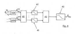
- variable steering ratio of the steering system calculates a desired engine angle specification or steering ratio ⁇ VSR / Md on the basis of vehicle speed v X , pinion angle ⁇ G and steering wheel angle ⁇ S (see also FIG. 4).
- VSR variable steering ratio
- the variable steering ratio VSR can be converted into a safe but still active substitute state.
- the variable steering ratio VSR must be turned off.
- the steering ratio ⁇ VSR / Md is reset in the event of a necessary correction of the steering wheel obliquity, as shown in FIG. 3 on the basis of a profile of the steering component ⁇ VSR / Md of the useful variable steering ratio VSR.
- the steering ratio ⁇ VSR / Md runs normally according to the specifications of the variable steering ratio VSR.
- variable steering ratio VSR and other useful functions LAFN determine in parallel to each sampling step, inter alia on the basis of their input signals, steering components ⁇ VSR / Md ,..., ⁇ LAFN / Md .
- These target values are filtered in a prefilter unit 40, then limited in reset units 41 in the presence of a steering wheel angle to be corrected (corresponding to FIG. 3 between t 1 and t 2 ) and finally superimposed or added in a coordinator 42.
- This overlay is essentially based on given priorities.
- variable steering ratio VSR has priority as a utility function and enters into the calculation as an absolute angle, while the steering components of the remaining useful functions ⁇ LAFN / Md only relative thereto (as the respective difference between the steering ratio ⁇ VSR / Md and the steering components ⁇ LAFN / Md ) are included in the calculation. Subsequently, a further limitation takes place in a unit 43 which supplies the desired motor angle specification or the control signal ⁇ Md to the actuator 13 or 23 as an output signal.
- the inventive method for operating a steering system is preferably as a computer program on the Controller 27 realized.
- This is the computer program in a memory element (not shown) of the Controller 27 is stored.
- the computer program can be on a computer readable medium (Floppy disk, hard disk, CD-ROM, DVD, SD card, etc.) or an Internet server as a computer program product be stored and from there into the memory element of the controller 27 are transmitted.
Landscapes
- Engineering & Computer Science (AREA)
- Chemical & Material Sciences (AREA)
- Combustion & Propulsion (AREA)
- Transportation (AREA)
- Mechanical Engineering (AREA)
- Steering Control In Accordance With Driving Conditions (AREA)
Abstract
Description
- Fig. 1 und 2
- ein Schema des Lenksystems nach dem Stand der Technik, von dem die Erfindung im Ausführungsbeispiel ausgeht;
- Fig. 3
- ein Diagramm eines Verlaufs eines Lenkanteils einer variablen Lenkübersetzung; und
- Fig. 4
- ein Schema zur Ermittlung eines gewünschten Motorwinkels innerhalb eines erfindungsgemäßen Verfahrens zum Betrieb eines Lenksystems.
Claims (9)
- Verfahren zum Betrieb eines Lenksystems für ein Kraftfahrzeug mit wenigstens einem lenkbaren Rad (15), einem Stellantrieb (13;23) und einem Überlagerungsgetriebe (12;22), wobei durch das Überlagerungsgetriebe (12;22) die durch den Fahrer des Fahrzeugs initiierte Lenkbewegung (δS) und die durch den Stellantrieb (13;23) initiierte Bewegung (δM) zur Erzeugung der Lenkbewegung des lenkbaren Rades (δFm) zur Realisierung von Nutzfunktionen in einen Ritzelwinkel (δG) überlagert werden, wobei der Stellantrieb (13;23) zur Initiierung der Bewegung (δM) durch ein Steuersignal (δMd) eines Steuergeräts (27) angesteuert wird,
dadurch gekennzeichnet , dass
ein kontrolliertes Zurückdrehen des Stellantriebs (13;23) bei einem Abschalten oder Schalten eines Ersatzmodus wenigstens einer Nutzfunktion (VSR,LAFN) des Lenksystems durchgeführt wird. - Verfahren nach Anspruch 1,
dadurch gekennzeichnet , dass
durch die Nutzfunktionen (VSR,LAFN) gebildete Lenkanteile (δ VSR / Md,δ LAFN / Md) zur Erzeugung des Steuersignals (δMd) überlagert werden, wobei die Lenkanteile (δ VSR / Md,δ LAFN / Md) zum kontrollierten Zurückdrehen des Stellantriebs (13;23) entsprechend begrenzt werden. - Verfahren nach Anspruch 1 oder 2,
dadurch gekennzeichnet , dass das Steuergerät (27) den Lenkradwinkel (δS), den Ritzelwinkel (δG) und weitere fahrzeugspezifische Parameter, insbesondere eine Fahrzeuggeschwindigkeit (VX) als Eingangssignale erhält, wobei das Abschalten oder das Schalten eines Ersatzmodus wenigstens einer Nutzfunktion aufgrund fehlerhafter Eingangssignale (vX,δG,δS) des Steuergeräts (27) erfolgt. - Verfahren nach Anspruch 1, 2 oder 3,
dadurch gekennzeichnet , dass
als Nutzfunktion eine variable Lenkübersetzung (VSR), eine Vorhaltelenkung oder eine Fahrdynamikstabilisierung eingesetzt wird. - Verfahren nach einem der Ansprüche 1 bis 4,
dadurch gekennzeichnet , dass
das kontrollierte Zurückdrehen des Stellantriebs (13;23) langsam mittels einer niedrigen Winkelgeschwindigkeit erfolgt. - Verfahren nach Anspruch 1 bis 5,
dadurch gekennzeichnet , dass
der Verlauf des Steuersignals (δMd) für den Motorwinkel (δM) des Stellantriebs (13;23) bei dem kontrollierten Zurückdrehen stetig ist. - Computerprogramm mit Programmcodemitteln, um ein Verfahren gemäß einem der Ansprüche 1 bis 6 durchzuführen, wenn dass Programm auf einem Computer insbesondere auf dem Steuergerät (27) des Lenksystems ausgeführt wird.
- Computerprogrammprodukt mit Programmcodemitteln, die auf einem computerlesbaren Datenträger gespeichert sind, um ein Verfahren gemäß einem der Ansprüche 1 bis 6 durchzuführen, wenn dass Programm auf einem Mikroprozessor eines Computers, insbesondere auf dem Steuergerät (27) des Lenksystems, ausgeführt wird.
- Steuergerät (27) für ein Lenksystem, welches zur Ausführung eines Computerprogramms gemäß Anspruch 7 eingerichtet ist.
Applications Claiming Priority (2)
| Application Number | Priority Date | Filing Date | Title |
|---|---|---|---|
| DE102004028829 | 2004-06-15 | ||
| DE102004028829A DE102004028829A1 (de) | 2004-06-15 | 2004-06-15 | Verfahren zum Betrieb eines Lenksystems |
Publications (3)
| Publication Number | Publication Date |
|---|---|
| EP1607307A2 true EP1607307A2 (de) | 2005-12-21 |
| EP1607307A3 EP1607307A3 (de) | 2006-04-12 |
| EP1607307B1 EP1607307B1 (de) | 2007-07-04 |
Family
ID=34939758
Family Applications (1)
| Application Number | Title | Priority Date | Filing Date |
|---|---|---|---|
| EP05103860A Expired - Lifetime EP1607307B1 (de) | 2004-06-15 | 2005-05-10 | Verfahren zum Betrieb eines Lenksystems |
Country Status (3)
| Country | Link |
|---|---|
| US (1) | US8083021B2 (de) |
| EP (1) | EP1607307B1 (de) |
| DE (2) | DE102004028829A1 (de) |
Families Citing this family (10)
| Publication number | Priority date | Publication date | Assignee | Title |
|---|---|---|---|---|
| DE102004019526A1 (de) * | 2004-04-22 | 2005-11-10 | Bayerische Motoren Werke Ag | Hydraulisches Servolenksystem |
| DE102008036039B4 (de) * | 2008-08-01 | 2010-07-22 | Bayerische Motoren Werke Aktiengesellschaft | Verfahren zur Überwachung und Ansteuerung eines Positions-Stellers |
| DE102008038882B4 (de) * | 2008-08-08 | 2019-02-14 | Volkswagen Ag | Verfahren zur Umsetzung einer Lenkmomentempfehlung durch eine elektromechanische Lenkung und ein Steuergerät |
| CH700243A1 (de) | 2009-01-12 | 2010-07-15 | Ferag Ag | Computergesteuertes fördersystem und förderverfahren. |
| DE102009002743B4 (de) * | 2009-04-30 | 2022-02-10 | Ford Global Technologies, Llc | Verfahren zum Betreiben eines aktiven Lenksystems sowie aktives Lenksystem |
| DE102009028181B4 (de) * | 2009-08-03 | 2016-01-28 | Ford Global Technologies, Llc | Pull-Drift-Kompensation mittels AFS |
| DE102009051471A1 (de) * | 2009-10-30 | 2011-05-05 | Audi Ag | Aktives Lenksystem für Kraftfahrzeuge |
| US8798865B1 (en) | 2013-02-05 | 2014-08-05 | Ford Global Technologies, Llc | Pull-drift compensation enhancements |
| JP6153438B2 (ja) * | 2013-09-30 | 2017-06-28 | マツダ株式会社 | 車両用操舵装置および操舵輪の自励振動検知方法 |
| DE102015212857B4 (de) * | 2014-07-09 | 2016-03-10 | Volkswagen Aktiengesellschaft | Justierungsvorrichtung und Verfahren zum Justieren der Mittelstellung eines Lenkrades eines Fahrzeuges |
Citations (1)
| Publication number | Priority date | Publication date | Assignee | Title |
|---|---|---|---|---|
| DE19751125A1 (de) | 1997-03-22 | 1998-09-24 | Bosch Gmbh Robert | Verfahren und Vorrichtung zum Betrieb eines Lenksystems für ein Kraftfahrzeug |
Family Cites Families (20)
| Publication number | Priority date | Publication date | Assignee | Title |
|---|---|---|---|---|
| JPH0624953B2 (ja) * | 1986-04-08 | 1994-04-06 | 本田技研工業株式会社 | 電動式パワ−ステアリング装置 |
| US4726437A (en) * | 1986-05-05 | 1988-02-23 | Peter Norton | Servo steering system |
| US4979114A (en) * | 1988-04-21 | 1990-12-18 | Fuji Jukogyo Kabushiki Kaisha | Motor control apparatus for electric power steering system |
| US4956590A (en) * | 1988-10-06 | 1990-09-11 | Techco Corporation | Vehicular power steering system |
| US5122958A (en) * | 1989-07-31 | 1992-06-16 | Toyoda Koki Kabushiki Kaisha | Apparatus for controlling steering force produced by power steering system |
| US6446749B2 (en) * | 1997-04-02 | 2002-09-10 | Robert Bosch Gmbh | Method and arrangement for operating a steering system for a motor vehicle |
| US6152254A (en) * | 1998-06-23 | 2000-11-28 | Techco Corporation | Feedback and servo control for electric power steering system with hydraulic transmission |
| DE19902939B4 (de) * | 1998-09-02 | 2015-01-08 | Continental Teves Ag & Co. Ohg | Verfahren und Vorrichtung zum Ersetzen eines fehlerhaften Sensorsignals |
| SE520459C2 (sv) * | 1998-09-11 | 2003-07-15 | Inmotion Technologies Ab | Servostyrsystem med positionskalibrerande anordning för elektriska fordon |
| DE10032340A1 (de) * | 2000-07-04 | 2002-01-31 | Bosch Gmbh Robert | Verfahren zum Lenken eines Fahrzeugs mit Servolenkung |
| JP4670161B2 (ja) * | 2000-07-13 | 2011-04-13 | マツダ株式会社 | 自動車の電動パワーステアリング装置 |
| DE10045385A1 (de) * | 2000-09-14 | 2002-03-28 | Bayerische Motoren Werke Ag | Vorrichtung und Verfahren zur elektronischen Steuerung eines einem Regelsystem zugeordneten Aktuators in Kraftfahrzeugen |
| US6570352B2 (en) * | 2000-11-17 | 2003-05-27 | Nsk Ltd. | Control unit for electric power steering apparatus |
| US6547031B1 (en) * | 2001-10-16 | 2003-04-15 | Delphi Technologies, Inc. | Front wheel steering variable control actuator |
| JP2004050978A (ja) * | 2002-07-19 | 2004-02-19 | Honda Motor Co Ltd | タイヤの線形領域判定装置及びタイヤの線形領域判定プログラム、並びに車両の運転操作装置及びステアバイワイヤ車両の転舵制御方法 |
| US6817620B1 (en) * | 2002-08-02 | 2004-11-16 | Durrell U Howard | Precision steer wheel control system with internal solenoid |
| DE10247975B4 (de) * | 2002-10-15 | 2014-03-27 | Robert Bosch Gmbh | Verfahren zum Betreiben einer Lenkung, ein Computerprogramm, ein Steuergerät sowie eine Lenkung für ein Fahrzeug |
| US6942058B2 (en) * | 2003-10-27 | 2005-09-13 | Ford Global Technologies, Llc | Vehicle steering system for kickback reduction |
| EP1682399B1 (de) * | 2003-11-13 | 2007-08-29 | Bayerische Motoren Werke Aktiengesellschaft | Hilfskraftunterstütztes lenksystem eines kraftfahrzeugs |
| JP3966274B2 (ja) * | 2003-12-04 | 2007-08-29 | トヨタ自動車株式会社 | 操舵制御装置 |
-
2004
- 2004-06-15 DE DE102004028829A patent/DE102004028829A1/de not_active Withdrawn
-
2005
- 2005-05-10 DE DE502005000960T patent/DE502005000960D1/de not_active Expired - Lifetime
- 2005-05-10 EP EP05103860A patent/EP1607307B1/de not_active Expired - Lifetime
- 2005-05-19 US US11/134,579 patent/US8083021B2/en not_active Expired - Fee Related
Patent Citations (1)
| Publication number | Priority date | Publication date | Assignee | Title |
|---|---|---|---|---|
| DE19751125A1 (de) | 1997-03-22 | 1998-09-24 | Bosch Gmbh Robert | Verfahren und Vorrichtung zum Betrieb eines Lenksystems für ein Kraftfahrzeug |
Also Published As
| Publication number | Publication date |
|---|---|
| US8083021B2 (en) | 2011-12-27 |
| DE502005000960D1 (de) | 2007-08-16 |
| DE102004028829A1 (de) | 2005-12-29 |
| US20050279564A1 (en) | 2005-12-22 |
| EP1607307A3 (de) | 2006-04-12 |
| EP1607307B1 (de) | 2007-07-04 |
Similar Documents
| Publication | Publication Date | Title |
|---|---|---|
| DE102009028181B4 (de) | Pull-Drift-Kompensation mittels AFS | |
| EP2029411B1 (de) | Elektromechanische lenkung mit lenkempfehlung | |
| DE4422031B4 (de) | Fahrzeuglenksystem | |
| DE102014200100B4 (de) | Lenkwinkelfehlerkorrektur | |
| WO2021122160A1 (de) | Steer-by-Wire-Lenksystem, Verfahren zum Betrieb eines Steer-by-Wire-Lenksystems und Fahrzeug | |
| DE10247975B4 (de) | Verfahren zum Betreiben einer Lenkung, ein Computerprogramm, ein Steuergerät sowie eine Lenkung für ein Fahrzeug | |
| WO2016087118A1 (de) | Lenkvorrichtung sowie verfahren zur steuerung einer lenkvorrichtung | |
| EP3392120A1 (de) | Steer-by-wire-lenkung und verfahren zur einstellung eines lenkwinkels bei einer steer-by-wire-lenkung | |
| EP1607307B1 (de) | Verfahren zum Betrieb eines Lenksystems | |
| WO2012065961A1 (de) | Verfahren zum betreiben einer hilfskraftlenkung | |
| WO2012000574A1 (de) | Verfahren zum elektromechanischen einstellen eines lenkwinkels und kraftfahrzeug mit einer elektromechanischen lenkung | |
| EP4339073B1 (de) | Sicherheitssystem zur fahrzeugquerführung für ein steer-by-wire lenksystem eines kraftfahrzeuges, sicherheitsverfahren und kraftfahrzeug | |
| EP4155170B1 (de) | Lenksystem und verfahren zum betreiben eines lenksystems | |
| WO2023174608A1 (de) | Verfahren zum betrieb eines lenksystems eines fahrzeugs | |
| DE102004048495A1 (de) | Verfahren zur Verbesserung des Betriebs einer Fahrzeuglenkung und Fahrzeuglenkung | |
| DE102021212197B3 (de) | Steer-by-wire-Lenksystem und Verfahren zum Betreiben eines steer-by-wire-Lenksystems | |
| DE102004028827A1 (de) | Verfahren zum Betrieb eines Lenksystems | |
| DE102004058996A1 (de) | Verfahren und Fahrfunktionssystem zum Überführen von sicherheitsrelevanten Fahrfunktionen eines Fahrzeugs in den sicheren Zustand | |
| DE102020211657A1 (de) | Lenksystem und Verfahren zum Betreiben eines Lenksystems | |
| EP3676159B1 (de) | Lenkungssteuergerät und verfahren zur ermittlung eines stellsignals für eine leistungselektronik einer lenkeinrichtung eines kraftfahrzeugs | |
| EP1568575B1 (de) | Verfahren zum Betrieb eines Lenksystems mit Konfiguration von Nutzanwendungen | |
| EP1568570A2 (de) | Berechnung eines Radwinkels eines Fahrzeugs | |
| DE102008000365A1 (de) | Steer by Wire Lenkung für ein Kraftfahrzeug | |
| EP4680513A1 (de) | Steer-by-wire-system für ein kraftfahrzeug sowie verfahren | |
| EP1925529B1 (de) | Lenkwinkelerkennung über elektronisches Stabilitäts-Program und elektrische Servolenkung |
Legal Events
| Date | Code | Title | Description |
|---|---|---|---|
| PUAI | Public reference made under article 153(3) epc to a published international application that has entered the european phase |
Free format text: ORIGINAL CODE: 0009012 |
|
| AK | Designated contracting states |
Kind code of ref document: A2 Designated state(s): AT BE BG CH CY CZ DE DK EE ES FI FR GB GR HU IE IS IT LI LT LU MC NL PL PT RO SE SI SK TR |
|
| AX | Request for extension of the european patent |
Extension state: AL BA HR LV MK YU |
|
| PUAL | Search report despatched |
Free format text: ORIGINAL CODE: 0009013 |
|
| AK | Designated contracting states |
Kind code of ref document: A3 Designated state(s): AT BE BG CH CY CZ DE DK EE ES FI FR GB GR HU IE IS IT LI LT LU MC NL PL PT RO SE SI SK TR |
|
| AX | Request for extension of the european patent |
Extension state: AL BA HR LV MK YU |
|
| 17P | Request for examination filed |
Effective date: 20060314 |
|
| RIC1 | Information provided on ipc code assigned before grant |
Ipc: B62D 6/00 20060101AFI20060623BHEP Ipc: B62D 137/00 20060101ALI20060623BHEP |
|
| GRAP | Despatch of communication of intention to grant a patent |
Free format text: ORIGINAL CODE: EPIDOSNIGR1 |
|
| GRAS | Grant fee paid |
Free format text: ORIGINAL CODE: EPIDOSNIGR3 |
|
| AKX | Designation fees paid |
Designated state(s): DE FR GB IT SE |
|
| GRAA | (expected) grant |
Free format text: ORIGINAL CODE: 0009210 |
|
| AK | Designated contracting states |
Kind code of ref document: B1 Designated state(s): DE FR GB IT SE |
|
| REG | Reference to a national code |
Ref country code: GB Ref legal event code: FG4D Free format text: NOT ENGLISH |
|
| REF | Corresponds to: |
Ref document number: 502005000960 Country of ref document: DE Date of ref document: 20070816 Kind code of ref document: P |
|
| ET | Fr: translation filed | ||
| GBV | Gb: ep patent (uk) treated as always having been void in accordance with gb section 77(7)/1977 [no translation filed] |
Effective date: 20070704 |
|
| PLBE | No opposition filed within time limit |
Free format text: ORIGINAL CODE: 0009261 |
|
| STAA | Information on the status of an ep patent application or granted ep patent |
Free format text: STATUS: NO OPPOSITION FILED WITHIN TIME LIMIT |
|
| PG25 | Lapsed in a contracting state [announced via postgrant information from national office to epo] |
Ref country code: GB Free format text: LAPSE BECAUSE OF FAILURE TO SUBMIT A TRANSLATION OF THE DESCRIPTION OR TO PAY THE FEE WITHIN THE PRESCRIBED TIME-LIMIT Effective date: 20070704 |
|
| 26N | No opposition filed |
Effective date: 20080407 |
|
| PG25 | Lapsed in a contracting state [announced via postgrant information from national office to epo] |
Ref country code: SE Free format text: LAPSE BECAUSE OF FAILURE TO SUBMIT A TRANSLATION OF THE DESCRIPTION OR TO PAY THE FEE WITHIN THE PRESCRIBED TIME-LIMIT Effective date: 20071004 |
|
| PGFP | Annual fee paid to national office [announced via postgrant information from national office to epo] |
Ref country code: IT Payment date: 20120516 Year of fee payment: 8 |
|
| PGFP | Annual fee paid to national office [announced via postgrant information from national office to epo] |
Ref country code: FR Payment date: 20130531 Year of fee payment: 9 |
|
| PG25 | Lapsed in a contracting state [announced via postgrant information from national office to epo] |
Ref country code: IT Free format text: LAPSE BECAUSE OF NON-PAYMENT OF DUE FEES Effective date: 20130510 |
|
| REG | Reference to a national code |
Ref country code: FR Ref legal event code: ST Effective date: 20150130 |
|
| PG25 | Lapsed in a contracting state [announced via postgrant information from national office to epo] |
Ref country code: FR Free format text: LAPSE BECAUSE OF NON-PAYMENT OF DUE FEES Effective date: 20140602 |
|
| REG | Reference to a national code |
Ref country code: DE Ref legal event code: R081 Ref document number: 502005000960 Country of ref document: DE Owner name: ROBERT BOSCH AUTOMOTIVE STEERING GMBH, DE Free format text: FORMER OWNER: ZF LENKSYSTEME GMBH, 73527 SCHWAEBISCH GMUEND, DE Effective date: 20150423 |
|
| PGFP | Annual fee paid to national office [announced via postgrant information from national office to epo] |
Ref country code: DE Payment date: 20180725 Year of fee payment: 14 |
|
| REG | Reference to a national code |
Ref country code: DE Ref legal event code: R119 Ref document number: 502005000960 Country of ref document: DE |
|
| PG25 | Lapsed in a contracting state [announced via postgrant information from national office to epo] |
Ref country code: DE Free format text: LAPSE BECAUSE OF NON-PAYMENT OF DUE FEES Effective date: 20191203 |