EP1607256A1 - Véhicule comportant un dispositif d'occultation escamotable - Google Patents
Véhicule comportant un dispositif d'occultation escamotable Download PDFInfo
- Publication number
- EP1607256A1 EP1607256A1 EP05300206A EP05300206A EP1607256A1 EP 1607256 A1 EP1607256 A1 EP 1607256A1 EP 05300206 A EP05300206 A EP 05300206A EP 05300206 A EP05300206 A EP 05300206A EP 1607256 A1 EP1607256 A1 EP 1607256A1
- Authority
- EP
- European Patent Office
- Prior art keywords
- vehicle according
- vehicle
- curtain
- deployed
- blade
- Prior art date
- Legal status (The legal status is an assumption and is not a legal conclusion. Google has not performed a legal analysis and makes no representation as to the accuracy of the status listed.)
- Granted
Links
- 239000013013 elastic material Substances 0.000 claims description 5
- 238000005253 cladding Methods 0.000 claims 1
- 239000011324 bead Substances 0.000 abstract 1
- 239000011521 glass Substances 0.000 description 7
- 239000006185 dispersion Substances 0.000 description 3
- 239000000463 material Substances 0.000 description 3
- 230000000694 effects Effects 0.000 description 2
- 238000004519 manufacturing process Methods 0.000 description 2
- 239000002759 woven fabric Substances 0.000 description 2
- 241000283153 Cetacea Species 0.000 description 1
- 238000004026 adhesive bonding Methods 0.000 description 1
- 239000005557 antagonist Substances 0.000 description 1
- 230000000295 complement effect Effects 0.000 description 1
- 239000002184 metal Substances 0.000 description 1
- 238000012986 modification Methods 0.000 description 1
- 230000004048 modification Effects 0.000 description 1
- 238000003032 molecular docking Methods 0.000 description 1
- 238000000465 moulding Methods 0.000 description 1
- 210000002445 nipple Anatomy 0.000 description 1
- 238000012856 packing Methods 0.000 description 1
Images

Classifications
-
- B—PERFORMING OPERATIONS; TRANSPORTING
- B60—VEHICLES IN GENERAL
- B60J—WINDOWS, WINDSCREENS, NON-FIXED ROOFS, DOORS, OR SIMILAR DEVICES FOR VEHICLES; REMOVABLE EXTERNAL PROTECTIVE COVERINGS SPECIALLY ADAPTED FOR VEHICLES
- B60J7/00—Non-fixed roofs; Roofs with movable panels, e.g. rotary sunroofs
- B60J7/0007—Non-fixed roofs; Roofs with movable panels, e.g. rotary sunroofs moveable head-liners, screens, curtains or blinds for ceilings
- B60J7/0015—Non-fixed roofs; Roofs with movable panels, e.g. rotary sunroofs moveable head-liners, screens, curtains or blinds for ceilings roller blind
Definitions
- the invention relates to a vehicle comprising a device concealable concealment, such as a curtain, to obscure a opening in his bodywork and more particularly in his pavilion.
- the bodies of motor vehicles or today have more and more surfaces windows and in particular the roofs still called pavilions of vehicles that tend to be equipped with glass panels of large dimensions.
- thermoelectric materials have been developed for make these glazed panels. These materials however remain expensive and fail to prevent any greenhouse effect.
- a relatively simple and effective solution is to provide glazed surfaces of light concealment systems.
- the occultation of a glass panel is conventionally carried out by deployment of a curtain or a set of slats or of joined panels.
- the free end of the occultation system can come into a predetermined game created between the glazed panel and an interior trim element coming through elsewhere mask the connection between the glazed panel and the body.
- Today such an unattractive game tends to vanish.
- Another solution is to come to support the free end of the occultation system against the interior trim element. Given the size of the surfaces to be concealed that make almost the entire width of the pavilion, the support surface of the occultation system is very important and it is difficult to account given manufacturing dispersions to guarantee a surface perfectly corresponding to that of the interior trim to allow support without a day and all the more so as the interior trim tends to be contoured.
- the present invention therefore aims to propose a vehicle adapted allowing a close pairing between the dressing inside and the means of occultation when these are in deployed position and this, whatever the dispersions dimensions of these parts.
- the vehicle according to the invention comprises a bodywork presenting an opening closed by a panel cooperating with means concealment devices, such as a curtain, between two positions extremes respectively retracted and deployed.
- the vehicle is characterized in that in position deployed extreme, the free transverse edge of the means occultation comes in support against a first element of interior lining extending into the passenger compartment of the vehicle, first interior trim element being shaped to be movable between a rest position and a work position corresponding to the deployed position of the occultation means, and in that this first element of interior lining cooperates with a second element of interior trim, this second element of interior trim being shaped to hide the area of contact between the first interior trim element and the means of occultation when they are in position deployed.
- the opening is provided in the roof and in that the first and second inner lining members form the interior trim of the front cross member.
- this interior dressing constitutes a structure continuous hollow concave extending along the longitudinal axis of the vehicle from substantially the windshield to the panel.
- said structure forming the covering of the cross front has an airplane wing shape having a substantially flat and raised inside edges.
- the first element of interior trim forms, in its rest position, the upper part of one of the edges Inward recesses of the structure forming the covering of the cross-bar before.
- the first element is distinct from the second element, this first element is slidably mounted on the second element and is subjected to the action of elastic return means.
- the first element is distinct from the second element, this first element is rotatably mounted on the second element and is subjected to the action of elastic return means.
- the first element is distinct from the second element and the first element is made of elastic material.
- the first element and the second element form a single piece made elastic material.
- the occultation means cooperate with means of driven motorized maneuvers.
- FIG. 1 shows a motor vehicle referenced 1 whose roof or flag 2 from which a wide opening has been made 3 intended to receive a glazed panel 4.
- the opening 3 is delimited by four structural elements of bodywork, namely two longitudinal elements called arcs of pavilions respectively 5 and 6 and two transverse elements, the front cross member 7, separating the windshield 9 of the roof 2, and the rear cross member 8, separating the roof 2 from the rear window 10.
- the various body elements 5 to 8 are shaped to receive the glazed panel 4 which is fixed by gluing on these structural elements.
- a concealer 11 is provided inside the vehicle to extend under the glass panel 4 and prevent light from entering the cockpit.
- This curtain 11 type curtain woven fabric could also be slat type or panels.
- This curtain 11 can be moved by maneuvering devices controlled also known and not figured. Under the influence of these means of maneuver, the curtain 11 moves between an extreme position deployed where the curtain 11 masks the glass panel 4 to occupants and an extreme folded position where the curtain is then completely retracted, for example in a non-figured receptacle under the rear crossmember 8 of the vehicle and masked by a interior trim adapted.
- maneuvering devices the concealer 11 include for example a gear motor and a system of return cables.
- guiding means such as rails 13 and 14 carried respectively by the arches of pavilions 5 and 6.
- the curtain 11 is constituted, for example, of a flexible woven fabric attached to one or more rigid sleepers such as arches or whales.
- the curtain 11 has a transverse rod 12 attached to the free end of the curtain and whose lateral ends are each provided with a slide cooperating respectively with one of the rails of guidance 13 and 14.
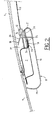
- This rod 12 is adapted to bear against a inner lining member 15 extending transversely in the cockpit to hide the occupants the front crossbar 7.
- the packing 15 forming the inner lining of the front cross member 7 constitutes a hollow concave continuous structure extending since substantially the windshield to the glass panel 4. This structure 15 is fixed directly to the front cross member 7.
- This crossbar 7 which is formed by a hollow beam of shape substantially parallelepiped present on its lower edge turned towards the cockpit a rabbet 16 extending outwardly while along the crossbar 7 for mounting the trim 15.
- the lining 15 made in two parts, comprises a fixed body 17 oblong come cast on which is slidably mounted a mobile blade 18 also came molding.
- This movable blade 18 is intended to face the wand 12 of the curtain 11 and to move under the action of the latter.
- the body 17 surrounds the cross member 7 on three sides. It has a flat bottom 19 and two raised side edges 20 and 21.
- the edge 20 slightly curved goes practically up to the right of the windshield 9 while the rounded edge 21 goes up, he way reentrant towards the glass panel 4 and up to level of the rebate 16 of the crossbar 7.
- the edge 21 ends with a re-entrant tablature 22 which extends substantially parallel to the bottom 19.
- This tab 22 is ends with a housing 23 delimited by two lips, this housing being intended to accommodate the rabbet rebate 16 before 7 and thus allow the assembly of the lining 15 on the crosses 7.
- Tablature 22 has on its upper face 24, directed towards the glazed panel 4, grooves 25 for example at the tail dovetail for sliding mounting of the movable blade 18 and also serving as an axial stop to the latter.
- the movable blade 18 has a lateral outer surface rounded 26 extending the edge 21 towards the glazed panel 4.
- the movable blade 18 also has on its underside complementary shapes 27 of the grooves 25 to allow the assembly of the movable blade 18 on the body 17 and its guiding in translation.
- Springs 27 forming elastic return means are arranged between the movable blade 18 and the crossbar 7. These springs 27 can for example be formed by metal rods welded to the body of the cross member 7 or springs helicals such as those shown in the accompanying drawings.
- the blade 18 is thus able to move between a position of rest where the springs 27 force the blade 18 against the body 17 and where the surface 26 perfectly extends the edge 21, and a recessed position where the blade 18 bears against the cross 7 by compressing the springs 27.
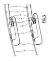
- the recessed position is caused by the action of the bar 12 which bears against the surface 26 of the blade 18 during the deployment of the blackout curtain 4 and which under the maneuvering means, force the blade 18 to back against the action antagonist of the return means 27.
- the contact zone between the blade 18 and the bar 12 is then hidden from the occupants by the leading edge 21. In this way the possible days between the bar 12 and the surface 26 due to the manufacturing dispersions are not visible to the occupants of the vehicle.
- nipples 28 carried by the bar 12 for example at the slides, and intended to penetrate recesses 29 correspondents carried by the blade 18.
- the invention while being simple and inexpensive structure, allows to realize a curtain retractable having an improved pairing of its free edge with the inner lining of the roof relative to the prior art.
- the present invention is not limited to the mode of realization that we have just described, and we can bring to these many changes and modifications without going out of the present invention.
- the invention relates to any interior trim 15 that can mask the contact area with the blackout curtain 11 when the bar 12 comes into contact with the surface corresponds to 26 of the lining 15.
- the blade 18 can be pivotally mounted and tilt under the action of the bar 12.
- the blade 18 can be fixed but made in the form of material elastic and deform under the action of the bar 12.
- the blade 18 can be integral with the portion 17 of the liner 15, this piece being then made of elastic material.
Landscapes
- Engineering & Computer Science (AREA)
- Mechanical Engineering (AREA)
- Curtains And Furnishings For Windows Or Doors (AREA)
- Turbine Rotor Nozzle Sealing (AREA)
- Lighting Device Outwards From Vehicle And Optical Signal (AREA)
- Lock And Its Accessories (AREA)
- Vehicle Waterproofing, Decoration, And Sanitation Devices (AREA)
Abstract
Description
- la figure 1 représente une vue partielle, de dessus, d'un toit de véhicule automobile équipé d'un rideau de toit escamotable selon l'invention.
- la figure 2 représente une vue partielle en coupe longitudinale du toit représenté à la figure 1.
- la figure 3 est une vue similaire à la figure 2 précisant le fonctionnement du dispositif selon l'invention.
Claims (10)
- Véhicule comportant une carrosserie (2) présentant une ouverture (3) fermée par un panneau (4) coopérant avec des moyens d'occultation (11) mobiles entre deux positions extrêmes respectivement escamotée et déployée, caractérisé en ce qu'en position extrême déployée, le bord libre (12) desdits moyens d'occultation (11) vient en appui contre un premier élément de garniture intérieure (18) s'étendant dans l'habitacle du véhicule, ledit premier élément (18) étant conformé pour être déplaçable entre une position de repos et une position de travail correspondant à la position déployée desdits moyens d'occultation (11), et en ce que ledit premier élément (18) coopère avec un second élément de garniture intérieure (17), ledit second élément étant conformé pour masquer la zone de contact entre ledit premier élément et lesdits moyens d'occultation lorsque ces derniers se trouvent en position déployée.
- Véhicule selon la revendication 1, caractérisé en ce que ladite ouverture (3) est ménagée dans le pavillon (2) et en ce que lesdits premier et second éléments (17,18) forment l'habillage intérieur (15) de la traverse avant (7).
- Véhicule selon la revendication 2, caractérisé en ce que ledit habillage constitue une structure continue concave creuse (15) s'étendant depuis sensiblement le pare-brise (9) jusqu'au panneau (4).
- Véhicule selon la revendication 3, caractérisé en ce que ladite structure (15) a une forme d'aile d'avion comportant un fond sensiblement plat (19) et des bords relevés rentrants (20, 21, 26).
- Véhicule selon la revendication 4, caractérisé en ce que ledit premier élément (18) forme la partie supérieure de l'un desdits bords relevés rentrants (26).
- Véhicule selon l'une quelconque des revendications 2 à 4, caractérisé en ce que ledit premier élément (18) est distinct dudit second élément (17), en ce que ledit premier élément (18) est monté coulissant sur ledit second élément (17) et en ce que ledit premier élément (18) est soumis à l'action de moyens élastiques de rappel (27).
- Véhicule selon l'une quelconque des revendications 2 à 4, caractérisé en ce que ledit premier élément (18) est distinct dudit second élément (17), en ce que ledit premier élément (18) est monté à rotation sur ledit second élément (17) et en ce que ledit premier élément (18) est soumis à l'action de moyens élastiques de rappel (27).
- Véhicule selon l'une quelconque des revendications 2 à 4, caractérisé en ce que ledit premier élément (18) est distinct dudit second élément (17), en ce que ledit premier élément (18) est réalisé en matériau élastique.
- Véhicule selon l'une quelconque des revendications 2 à 4, caractérisé en ce que ledit premier élément (18) et ledit second élément (17) forment une unique pièce réalisée matériau élastique.
- Véhicule selon l'une quelconque des revendications 2 à 7, caractérisé en ce que lesdits moyens d'occultation coopèrent avec des moyens de manoeuvre motorisés pilotés.
Applications Claiming Priority (2)
| Application Number | Priority Date | Filing Date | Title |
|---|---|---|---|
| FR0404070 | 2004-04-19 | ||
| FR0404070A FR2868993B1 (fr) | 2004-04-19 | 2004-04-19 | Vehicule comportant un dispositif d'occultation escamotable |
Publications (2)
| Publication Number | Publication Date |
|---|---|
| EP1607256A1 true EP1607256A1 (fr) | 2005-12-21 |
| EP1607256B1 EP1607256B1 (fr) | 2008-11-05 |
Family
ID=34942517
Family Applications (1)
| Application Number | Title | Priority Date | Filing Date |
|---|---|---|---|
| EP05300206A Expired - Lifetime EP1607256B1 (fr) | 2004-04-19 | 2005-03-22 | Véhicule comportant un dispositif d'occultation escamotable |
Country Status (4)
| Country | Link |
|---|---|
| EP (1) | EP1607256B1 (fr) |
| AT (1) | ATE413301T1 (fr) |
| DE (1) | DE602005010785D1 (fr) |
| FR (1) | FR2868993B1 (fr) |
Citations (6)
| Publication number | Priority date | Publication date | Assignee | Title |
|---|---|---|---|---|
| US6186587B1 (en) * | 1998-12-01 | 2001-02-13 | Webasto Karosseriesysteme Gmbh | Blind arrangement for vehicles |
| US6386626B1 (en) * | 1999-11-18 | 2002-05-14 | Aisin Seiki Kabushiki Kaisha | Sunshade for vehicle sunroof |
| US20030006630A1 (en) * | 2001-05-09 | 2003-01-09 | Webasto Vehicle Systems International Gmbh | Sunshade for a motor vehicle roof |
| US6513864B2 (en) * | 2000-08-08 | 2003-02-04 | Arvinmeritor Gmbh | Modular vehicle roof |
| US20030193218A1 (en) * | 2000-07-14 | 2003-10-16 | Howa Textile Industry Co., Ltd. | Sliding sunshade of sunroof for automobile |
| US20040040676A1 (en) * | 2002-08-29 | 2004-03-04 | Webasto Vehicle Systems International Gmbh | Shade tarp as sun shield |
-
2004
- 2004-04-19 FR FR0404070A patent/FR2868993B1/fr not_active Expired - Fee Related
-
2005
- 2005-03-22 EP EP05300206A patent/EP1607256B1/fr not_active Expired - Lifetime
- 2005-03-22 AT AT05300206T patent/ATE413301T1/de not_active IP Right Cessation
- 2005-03-22 DE DE602005010785T patent/DE602005010785D1/de not_active Expired - Lifetime
Patent Citations (6)
| Publication number | Priority date | Publication date | Assignee | Title |
|---|---|---|---|---|
| US6186587B1 (en) * | 1998-12-01 | 2001-02-13 | Webasto Karosseriesysteme Gmbh | Blind arrangement for vehicles |
| US6386626B1 (en) * | 1999-11-18 | 2002-05-14 | Aisin Seiki Kabushiki Kaisha | Sunshade for vehicle sunroof |
| US20030193218A1 (en) * | 2000-07-14 | 2003-10-16 | Howa Textile Industry Co., Ltd. | Sliding sunshade of sunroof for automobile |
| US6513864B2 (en) * | 2000-08-08 | 2003-02-04 | Arvinmeritor Gmbh | Modular vehicle roof |
| US20030006630A1 (en) * | 2001-05-09 | 2003-01-09 | Webasto Vehicle Systems International Gmbh | Sunshade for a motor vehicle roof |
| US20040040676A1 (en) * | 2002-08-29 | 2004-03-04 | Webasto Vehicle Systems International Gmbh | Shade tarp as sun shield |
Also Published As
| Publication number | Publication date |
|---|---|
| ATE413301T1 (de) | 2008-11-15 |
| EP1607256B1 (fr) | 2008-11-05 |
| FR2868993A1 (fr) | 2005-10-21 |
| FR2868993B1 (fr) | 2006-06-16 |
| DE602005010785D1 (de) | 2008-12-18 |
Similar Documents
| Publication | Publication Date | Title |
|---|---|---|
| WO2017055577A1 (fr) | Dispositif vitré affleurant pour porte de véhicule, porte, véhicule automobile, procédé de fabrication et dispositif d'étanchéité correspondants | |
| EP3582986B1 (fr) | Dispositif vitre affleurant pour porte de vehicule, porte, vehicule automobile, procede de fabrication et dispositif d'etancheite monobloc correspondants | |
| WO2018109295A1 (fr) | Structure de vehicule automobile à toit ouvrant, cadre de pavillon et pavillon correspondant | |
| FR2696375A1 (fr) | Agencement de véhicule automobile transformable en véhicule découvert. | |
| FR2726512A1 (fr) | Toit ouvrant de vehicule a plusieurs panneaux | |
| EP2743175A1 (fr) | Fond étanche avant d'aéronef comprenant des renfoncements pour le logement d'équipements de cockpit | |
| FR2909594A1 (fr) | Pavillon vitre de vehicule automobile,procede de montage et vehicule correspondants | |
| FR2985225A1 (fr) | Pavillon vitre de vehicule, equipe d'un panneau mobile coulissant, et vehicule correspondant | |
| EP1607256B1 (fr) | Véhicule comportant un dispositif d'occultation escamotable | |
| WO2008040892A1 (fr) | Dispositif d'occultation d'un pare-brise de vehicule | |
| EP1538012A2 (fr) | Dispositif d'obturation d'une ouverture pour véhicule automobile, procédé de fabrication et véhicule correspondant. | |
| EP1769954B1 (fr) | Palettes pare-soleil pour pare-brise de véhicule automobile, à store à enrouleur, et véhicule automobile correspondant | |
| FR2864476A1 (fr) | Vehicule automobile dote d'un toit ouvrant panoramique | |
| EP2516242B1 (fr) | Piece de structure | |
| EP2230115B1 (fr) | Dispositif d'occultation d'un pavillon vitre d'un vehicule automobile, et vehicule automobile correspondant | |
| FR2551700A1 (fr) | Deflecteur de vent | |
| FR2948900A1 (fr) | Dispositif d'occultation d'un element vitre d'un pavillon de vehicule | |
| EP1683667B1 (fr) | Dispositif d'occultation pour véhicule automobile comprenant un écran enroulable, et véhicule correspondant | |
| FR3054818A1 (fr) | Structure de pavillon pour toit ouvrant, formant renfort de caisse. | |
| FR2892064A1 (fr) | Toit mobile pour vehicule monocorps ou bicorps. | |
| EP2041836B1 (fr) | Ensemble pare-soleil pour véhicule | |
| EP1800924B1 (fr) | Véhicule automobile comportant des pare-soleils escamotables dans une traverse longitudinale centrale du toit dudit véhicule | |
| FR2926057A1 (fr) | Cadre renforce pour panneau vitre de toit de vehicule automobile | |
| EP1440830A1 (fr) | Dispositif d'occultation du pavillon et d'une partie supérieure du pare-brise d'un véhicule automobile | |
| FR2905901A1 (fr) | Module de pavillon pour vehicule automobile |
Legal Events
| Date | Code | Title | Description |
|---|---|---|---|
| PUAI | Public reference made under article 153(3) epc to a published international application that has entered the european phase |
Free format text: ORIGINAL CODE: 0009012 |
|
| AK | Designated contracting states |
Kind code of ref document: A1 Designated state(s): AT BE BG CH CY CZ DE DK EE ES FI FR GB GR HU IE IS IT LI LT LU MC NL PL PT RO SE SI SK TR |
|
| AX | Request for extension of the european patent |
Extension state: AL BA HR LV MK YU |
|
| 17P | Request for examination filed |
Effective date: 20060113 |
|
| AKX | Designation fees paid |
Designated state(s): AT BE BG CH CY CZ DE DK EE ES FI FR GB GR HU IE IS IT LI LT LU MC NL PL PT RO SE SI SK TR |
|
| GRAP | Despatch of communication of intention to grant a patent |
Free format text: ORIGINAL CODE: EPIDOSNIGR1 |
|
| GRAS | Grant fee paid |
Free format text: ORIGINAL CODE: EPIDOSNIGR3 |
|
| GRAA | (expected) grant |
Free format text: ORIGINAL CODE: 0009210 |
|
| AK | Designated contracting states |
Kind code of ref document: B1 Designated state(s): AT BE BG CH CY CZ DE DK EE ES FI FR GB GR HU IE IS IT LI LT LU MC NL PL PT RO SE SI SK TR |
|
| REG | Reference to a national code |
Ref country code: GB Ref legal event code: FG4D Free format text: NOT ENGLISH |
|
| REG | Reference to a national code |
Ref country code: CH Ref legal event code: EP |
|
| REG | Reference to a national code |
Ref country code: IE Ref legal event code: FG4D Free format text: LANGUAGE OF EP DOCUMENT: FRENCH |
|
| REF | Corresponds to: |
Ref document number: 602005010785 Country of ref document: DE Date of ref document: 20081218 Kind code of ref document: P |
|
| REG | Reference to a national code |
Ref country code: GB Ref legal event code: 746 Effective date: 20081222 |
|
| NLV1 | Nl: lapsed or annulled due to failure to fulfill the requirements of art. 29p and 29m of the patents act | ||
| LTIE | Lt: invalidation of european patent or patent extension |
Effective date: 20081105 |
|
| PG25 | Lapsed in a contracting state [announced via postgrant information from national office to epo] |
Ref country code: LT Free format text: LAPSE BECAUSE OF FAILURE TO SUBMIT A TRANSLATION OF THE DESCRIPTION OR TO PAY THE FEE WITHIN THE PRESCRIBED TIME-LIMIT Effective date: 20081105 Ref country code: AT Free format text: LAPSE BECAUSE OF FAILURE TO SUBMIT A TRANSLATION OF THE DESCRIPTION OR TO PAY THE FEE WITHIN THE PRESCRIBED TIME-LIMIT Effective date: 20081105 Ref country code: ES Free format text: LAPSE BECAUSE OF FAILURE TO SUBMIT A TRANSLATION OF THE DESCRIPTION OR TO PAY THE FEE WITHIN THE PRESCRIBED TIME-LIMIT Effective date: 20090216 |
|
| PG25 | Lapsed in a contracting state [announced via postgrant information from national office to epo] |
Ref country code: SI Free format text: LAPSE BECAUSE OF FAILURE TO SUBMIT A TRANSLATION OF THE DESCRIPTION OR TO PAY THE FEE WITHIN THE PRESCRIBED TIME-LIMIT Effective date: 20081105 Ref country code: PL Free format text: LAPSE BECAUSE OF FAILURE TO SUBMIT A TRANSLATION OF THE DESCRIPTION OR TO PAY THE FEE WITHIN THE PRESCRIBED TIME-LIMIT Effective date: 20081105 Ref country code: NL Free format text: LAPSE BECAUSE OF FAILURE TO SUBMIT A TRANSLATION OF THE DESCRIPTION OR TO PAY THE FEE WITHIN THE PRESCRIBED TIME-LIMIT Effective date: 20081105 Ref country code: IS Free format text: LAPSE BECAUSE OF FAILURE TO SUBMIT A TRANSLATION OF THE DESCRIPTION OR TO PAY THE FEE WITHIN THE PRESCRIBED TIME-LIMIT Effective date: 20090305 Ref country code: FI Free format text: LAPSE BECAUSE OF FAILURE TO SUBMIT A TRANSLATION OF THE DESCRIPTION OR TO PAY THE FEE WITHIN THE PRESCRIBED TIME-LIMIT Effective date: 20081105 |
|
| REG | Reference to a national code |
Ref country code: IE Ref legal event code: FD4D |
|
| PG25 | Lapsed in a contracting state [announced via postgrant information from national office to epo] |
Ref country code: IE Free format text: LAPSE BECAUSE OF FAILURE TO SUBMIT A TRANSLATION OF THE DESCRIPTION OR TO PAY THE FEE WITHIN THE PRESCRIBED TIME-LIMIT Effective date: 20081105 Ref country code: DK Free format text: LAPSE BECAUSE OF FAILURE TO SUBMIT A TRANSLATION OF THE DESCRIPTION OR TO PAY THE FEE WITHIN THE PRESCRIBED TIME-LIMIT Effective date: 20081105 Ref country code: EE Free format text: LAPSE BECAUSE OF FAILURE TO SUBMIT A TRANSLATION OF THE DESCRIPTION OR TO PAY THE FEE WITHIN THE PRESCRIBED TIME-LIMIT Effective date: 20081105 Ref country code: RO Free format text: LAPSE BECAUSE OF FAILURE TO SUBMIT A TRANSLATION OF THE DESCRIPTION OR TO PAY THE FEE WITHIN THE PRESCRIBED TIME-LIMIT Effective date: 20081105 Ref country code: BG Free format text: LAPSE BECAUSE OF FAILURE TO SUBMIT A TRANSLATION OF THE DESCRIPTION OR TO PAY THE FEE WITHIN THE PRESCRIBED TIME-LIMIT Effective date: 20090205 |
|
| PG25 | Lapsed in a contracting state [announced via postgrant information from national office to epo] |
Ref country code: CZ Free format text: LAPSE BECAUSE OF FAILURE TO SUBMIT A TRANSLATION OF THE DESCRIPTION OR TO PAY THE FEE WITHIN THE PRESCRIBED TIME-LIMIT Effective date: 20081105 Ref country code: PT Free format text: LAPSE BECAUSE OF FAILURE TO SUBMIT A TRANSLATION OF THE DESCRIPTION OR TO PAY THE FEE WITHIN THE PRESCRIBED TIME-LIMIT Effective date: 20090406 Ref country code: SE Free format text: LAPSE BECAUSE OF FAILURE TO SUBMIT A TRANSLATION OF THE DESCRIPTION OR TO PAY THE FEE WITHIN THE PRESCRIBED TIME-LIMIT Effective date: 20090205 |
|
| PLBE | No opposition filed within time limit |
Free format text: ORIGINAL CODE: 0009261 |
|
| STAA | Information on the status of an ep patent application or granted ep patent |
Free format text: STATUS: NO OPPOSITION FILED WITHIN TIME LIMIT |
|
| BERE | Be: lapsed |
Owner name: PEUGEOT CITROEN AUTOMOBILES S.A. Effective date: 20090331 |
|
| PG25 | Lapsed in a contracting state [announced via postgrant information from national office to epo] |
Ref country code: SK Free format text: LAPSE BECAUSE OF FAILURE TO SUBMIT A TRANSLATION OF THE DESCRIPTION OR TO PAY THE FEE WITHIN THE PRESCRIBED TIME-LIMIT Effective date: 20081105 |
|
| 26N | No opposition filed |
Effective date: 20090806 |
|
| PG25 | Lapsed in a contracting state [announced via postgrant information from national office to epo] |
Ref country code: MC Free format text: LAPSE BECAUSE OF NON-PAYMENT OF DUE FEES Effective date: 20090331 |
|
| REG | Reference to a national code |
Ref country code: CH Ref legal event code: PL |
|
| PG25 | Lapsed in a contracting state [announced via postgrant information from national office to epo] |
Ref country code: LI Free format text: LAPSE BECAUSE OF NON-PAYMENT OF DUE FEES Effective date: 20090331 Ref country code: CH Free format text: LAPSE BECAUSE OF NON-PAYMENT OF DUE FEES Effective date: 20090331 |
|
| PG25 | Lapsed in a contracting state [announced via postgrant information from national office to epo] |
Ref country code: BE Free format text: LAPSE BECAUSE OF NON-PAYMENT OF DUE FEES Effective date: 20090331 |
|
| PG25 | Lapsed in a contracting state [announced via postgrant information from national office to epo] |
Ref country code: GR Free format text: LAPSE BECAUSE OF FAILURE TO SUBMIT A TRANSLATION OF THE DESCRIPTION OR TO PAY THE FEE WITHIN THE PRESCRIBED TIME-LIMIT Effective date: 20090206 |
|
| PG25 | Lapsed in a contracting state [announced via postgrant information from national office to epo] |
Ref country code: IT Free format text: LAPSE BECAUSE OF FAILURE TO SUBMIT A TRANSLATION OF THE DESCRIPTION OR TO PAY THE FEE WITHIN THE PRESCRIBED TIME-LIMIT Effective date: 20081105 |
|
| PG25 | Lapsed in a contracting state [announced via postgrant information from national office to epo] |
Ref country code: LU Free format text: LAPSE BECAUSE OF NON-PAYMENT OF DUE FEES Effective date: 20090322 |
|
| PG25 | Lapsed in a contracting state [announced via postgrant information from national office to epo] |
Ref country code: HU Free format text: LAPSE BECAUSE OF FAILURE TO SUBMIT A TRANSLATION OF THE DESCRIPTION OR TO PAY THE FEE WITHIN THE PRESCRIBED TIME-LIMIT Effective date: 20090506 |
|
| PG25 | Lapsed in a contracting state [announced via postgrant information from national office to epo] |
Ref country code: TR Free format text: LAPSE BECAUSE OF FAILURE TO SUBMIT A TRANSLATION OF THE DESCRIPTION OR TO PAY THE FEE WITHIN THE PRESCRIBED TIME-LIMIT Effective date: 20081105 |
|
| PG25 | Lapsed in a contracting state [announced via postgrant information from national office to epo] |
Ref country code: CY Free format text: LAPSE BECAUSE OF FAILURE TO SUBMIT A TRANSLATION OF THE DESCRIPTION OR TO PAY THE FEE WITHIN THE PRESCRIBED TIME-LIMIT Effective date: 20081105 |
|
| PGFP | Annual fee paid to national office [announced via postgrant information from national office to epo] |
Ref country code: FR Payment date: 20120410 Year of fee payment: 8 |
|
| PGFP | Annual fee paid to national office [announced via postgrant information from national office to epo] |
Ref country code: GB Payment date: 20130228 Year of fee payment: 9 |
|
| PGFP | Annual fee paid to national office [announced via postgrant information from national office to epo] |
Ref country code: DE Payment date: 20130913 Year of fee payment: 9 |
|
| REG | Reference to a national code |
Ref country code: FR Ref legal event code: ST Effective date: 20131129 |
|
| PG25 | Lapsed in a contracting state [announced via postgrant information from national office to epo] |
Ref country code: FR Free format text: LAPSE BECAUSE OF NON-PAYMENT OF DUE FEES Effective date: 20130402 |
|
| REG | Reference to a national code |
Ref country code: DE Ref legal event code: R119 Ref document number: 602005010785 Country of ref document: DE |
|
| GBPC | Gb: european patent ceased through non-payment of renewal fee |
Effective date: 20140322 |
|
| REG | Reference to a national code |
Ref country code: DE Ref legal event code: R119 Ref document number: 602005010785 Country of ref document: DE Effective date: 20141001 |
|
| PG25 | Lapsed in a contracting state [announced via postgrant information from national office to epo] |
Ref country code: DE Free format text: LAPSE BECAUSE OF NON-PAYMENT OF DUE FEES Effective date: 20141001 Ref country code: GB Free format text: LAPSE BECAUSE OF NON-PAYMENT OF DUE FEES Effective date: 20140322 |