EP1607158A1 - Procédé de fabrication d'un carter de stator de turbine - Google Patents
Procédé de fabrication d'un carter de stator de turbine Download PDFInfo
- Publication number
- EP1607158A1 EP1607158A1 EP05291251A EP05291251A EP1607158A1 EP 1607158 A1 EP1607158 A1 EP 1607158A1 EP 05291251 A EP05291251 A EP 05291251A EP 05291251 A EP05291251 A EP 05291251A EP 1607158 A1 EP1607158 A1 EP 1607158A1
- Authority
- EP
- European Patent Office
- Prior art keywords
- casing
- cores
- envelope
- inserts
- mold
- Prior art date
- Legal status (The legal status is an assumption and is not a legal conclusion. Google has not performed a legal analysis and makes no representation as to the accuracy of the status listed.)
- Granted
Links
Images

Classifications
-
- B—PERFORMING OPERATIONS; TRANSPORTING
- B22—CASTING; POWDER METALLURGY
- B22F—WORKING METALLIC POWDER; MANUFACTURE OF ARTICLES FROM METALLIC POWDER; MAKING METALLIC POWDER; APPARATUS OR DEVICES SPECIALLY ADAPTED FOR METALLIC POWDER
- B22F5/00—Manufacture of workpieces or articles from metallic powder characterised by the special shape of the product
- B22F5/04—Manufacture of workpieces or articles from metallic powder characterised by the special shape of the product of turbine blades
-
- B—PERFORMING OPERATIONS; TRANSPORTING
- B22—CASTING; POWDER METALLURGY
- B22F—WORKING METALLIC POWDER; MANUFACTURE OF ARTICLES FROM METALLIC POWDER; MAKING METALLIC POWDER; APPARATUS OR DEVICES SPECIALLY ADAPTED FOR METALLIC POWDER
- B22F3/00—Manufacture of workpieces or articles from metallic powder characterised by the manner of compacting or sintering; Apparatus specially adapted therefor ; Presses and furnaces
- B22F3/12—Both compacting and sintering
- B22F3/1208—Containers or coating used therefor
- B22F3/1258—Container manufacturing
-
- F—MECHANICAL ENGINEERING; LIGHTING; HEATING; WEAPONS; BLASTING
- F01—MACHINES OR ENGINES IN GENERAL; ENGINE PLANTS IN GENERAL; STEAM ENGINES
- F01D—NON-POSITIVE DISPLACEMENT MACHINES OR ENGINES, e.g. STEAM TURBINES
- F01D25/00—Component parts, details, or accessories, not provided for in, or of interest apart from, other groups
- F01D25/08—Cooling; Heating; Heat-insulation
- F01D25/14—Casings modified therefor
-
- F—MECHANICAL ENGINEERING; LIGHTING; HEATING; WEAPONS; BLASTING
- F01—MACHINES OR ENGINES IN GENERAL; ENGINE PLANTS IN GENERAL; STEAM ENGINES
- F01D—NON-POSITIVE DISPLACEMENT MACHINES OR ENGINES, e.g. STEAM TURBINES
- F01D25/00—Component parts, details, or accessories, not provided for in, or of interest apart from, other groups
- F01D25/24—Casings; Casing parts, e.g. diaphragms, casing fastenings
-
- B—PERFORMING OPERATIONS; TRANSPORTING
- B22—CASTING; POWDER METALLURGY
- B22F—WORKING METALLIC POWDER; MANUFACTURE OF ARTICLES FROM METALLIC POWDER; MAKING METALLIC POWDER; APPARATUS OR DEVICES SPECIALLY ADAPTED FOR METALLIC POWDER
- B22F2999/00—Aspects linked to processes or compositions used in powder metallurgy
-
- F—MECHANICAL ENGINEERING; LIGHTING; HEATING; WEAPONS; BLASTING
- F05—INDEXING SCHEMES RELATING TO ENGINES OR PUMPS IN VARIOUS SUBCLASSES OF CLASSES F01-F04
- F05D—INDEXING SCHEME FOR ASPECTS RELATING TO NON-POSITIVE-DISPLACEMENT MACHINES OR ENGINES, GAS-TURBINES OR JET-PROPULSION PLANTS
- F05D2230/00—Manufacture
- F05D2230/20—Manufacture essentially without removing material
- F05D2230/21—Manufacture essentially without removing material by casting
-
- F—MECHANICAL ENGINEERING; LIGHTING; HEATING; WEAPONS; BLASTING
- F05—INDEXING SCHEMES RELATING TO ENGINES OR PUMPS IN VARIOUS SUBCLASSES OF CLASSES F01-F04
- F05D—INDEXING SCHEME FOR ASPECTS RELATING TO NON-POSITIVE-DISPLACEMENT MACHINES OR ENGINES, GAS-TURBINES OR JET-PROPULSION PLANTS
- F05D2230/00—Manufacture
- F05D2230/20—Manufacture essentially without removing material
- F05D2230/22—Manufacture essentially without removing material by sintering
-
- Y—GENERAL TAGGING OF NEW TECHNOLOGICAL DEVELOPMENTS; GENERAL TAGGING OF CROSS-SECTIONAL TECHNOLOGIES SPANNING OVER SEVERAL SECTIONS OF THE IPC; TECHNICAL SUBJECTS COVERED BY FORMER USPC CROSS-REFERENCE ART COLLECTIONS [XRACs] AND DIGESTS
- Y02—TECHNOLOGIES OR APPLICATIONS FOR MITIGATION OR ADAPTATION AGAINST CLIMATE CHANGE
- Y02T—CLIMATE CHANGE MITIGATION TECHNOLOGIES RELATED TO TRANSPORTATION
- Y02T50/00—Aeronautics or air transport
- Y02T50/60—Efficient propulsion technologies, e.g. for aircraft
-
- Y—GENERAL TAGGING OF NEW TECHNOLOGICAL DEVELOPMENTS; GENERAL TAGGING OF CROSS-SECTIONAL TECHNOLOGIES SPANNING OVER SEVERAL SECTIONS OF THE IPC; TECHNICAL SUBJECTS COVERED BY FORMER USPC CROSS-REFERENCE ART COLLECTIONS [XRACs] AND DIGESTS
- Y10—TECHNICAL SUBJECTS COVERED BY FORMER USPC
- Y10T—TECHNICAL SUBJECTS COVERED BY FORMER US CLASSIFICATION
- Y10T29/00—Metal working
- Y10T29/49—Method of mechanical manufacture
- Y10T29/49316—Impeller making
- Y10T29/4932—Turbomachine making
-
- Y—GENERAL TAGGING OF NEW TECHNOLOGICAL DEVELOPMENTS; GENERAL TAGGING OF CROSS-SECTIONAL TECHNOLOGIES SPANNING OVER SEVERAL SECTIONS OF THE IPC; TECHNICAL SUBJECTS COVERED BY FORMER USPC CROSS-REFERENCE ART COLLECTIONS [XRACs] AND DIGESTS
- Y10—TECHNICAL SUBJECTS COVERED BY FORMER USPC
- Y10T—TECHNICAL SUBJECTS COVERED BY FORMER US CLASSIFICATION
- Y10T29/00—Metal working
- Y10T29/49—Method of mechanical manufacture
- Y10T29/49346—Rocket or jet device making
Definitions
- the invention relates to a method of manufacturing a stator housing turbine, and more particularly of an airplane turbojet turbine.
- Such a casing comprises a casing of general shape frustoconical on its inner side, turned towards the inside of the turbine, fixing hooks to support one or more turbine distributors formed by rings or segments of ring bearing vanes fixed. Between these distributors, there are movable wheels which carry the blades of the rotor of the turbine. The pair formed by a distributor and a moving wheel constitutes a floor of turbines.
- Turbines and more particularly turbojet turbines of aircraft, are traversed by very hot combustion gases whose temperatures can sometimes reach, for some floors of the turbine, 1100 ° C. Also, the casing shell is subject to a very important heating and it is necessary to cool the latter using a cooling system.
- double wall or double skin envelopes have been between their inner and outer skins free spaces in which fresh air is circulated.
- This embodiment nevertheless has certain disadvantages related to the very nature of casting.
- the precision The dimensional dimension of the molded envelope is difficult to control.
- the mechanical properties such as yield strength and fatigue strength of the envelope formed are not optimal, often because of the strong porosity of the latter or the presence in its mass of defects in structure that weakens it (these defects are often linked to non-uniform cooling of the molded part).
- the invention relates to a method of manufacturing crankcase turbine stator which makes it possible to produce double-skin casings with good dimensional accuracy, these envelopes having, in addition, good mechanical properties.
- Said free spaces are of course used to create paths of fresh air circulation in the thickness of the envelope.
- the envelopes produced according to the process of the invention have been from a known metal alloy powder under the Astroloy® brand, while the other envelopes were made from an alloy used in foundry known under the brand Inconel 718®.
- the method of the invention implements, between the cores, inserts materializing traffic paths between said free spaces; and we eliminate those inserts after the sintering operation.
- the tool shown in Figure 1 comprises a mold in several parts. Five of these parts are represented: three inner parts O1, O2 and O3 and two outer portions E1 and E2.
- the design of these mold parts is very rigorous. This design is assisted by computer and takes into account the local withdrawals occurring during the hot isostatic compression or C.I.C.
- This particular technique of C.I.C better known under the name "Isoprec® process” (trademark deposited), allows to obtain a casing envelope directly to dimensions and thus limit its subsequent machining.
- Nuclei 10 made of a material soluble in a solvent particular, are secured to the outer mold part E1 by means of Tubular pins 12. These pins 12 hold these cores 10 in position, instead of the free spaces 110 of fresh air circulation that we wish in the thickness of the casing 105.
- Each core 10 is either in the form of a ring or in the form of a ring segment (each segment being susceptible to be put end to end with other segments to form a ring full).
- Each peg 12 has two ends 12a and 12b, one of the ends 12a is mounted in a first housing 14, formed in the mold part E1, and the other end 12b is mounted in a second housing 16 formed in one of said cores 10.
- these pins 12 are tubular, they have a hole through 18 which opens at the ends 12a and 12b. These holes 18 constitute access routes to the cores 10 through which passes the solvent used to dissolve these.
- tubular pins 12 may also have a thread inside or outside. This thread is likely to be used to fix said tools may be used to set them up, or a cooling air supply line.
- the tooling shown in FIG. 1 further comprises inserts 20 disposed between the cores 10 and made of the same soluble material than these. To remain in position, the inserts 20 are fixed to the cores 10, by any suitable fastening means.
- housings 22, capable of receiving the ends 20a inserts 20 are provided at the edges of the cores 10, so that the inserts 20 can be nested in these cores 10.
- the powder grains 24 located between the cores 10 or the inserts 20 and the outer mold parts E1 are thereby forming the outer skin 105a of the envelope 105, while the grains of powder 24 located between the cores 10 or the inserts 20 and the inner mold parts O1, O2, O3, will form the inner skin 105b of the envelope 105.
- the mold parts are available around a support cylinder, not shown, and we pass around the outer mold parts a clamping ring.
- the assembly thus formed is placed in an autoclave under pressure elevated temperature, for example 1000 bar and 1200 ° C. Like him there is a slight clearance between the parts of the mold, the latter will deform in order to compress the powder 24. Under the cumulative effect of compression and high temperatures, this powder will become denser to form the casing 105 is the sintering step.
- the C.I.C. cycle it is possible to take advantage of the C.I.C. cycle to solidarize the pawns 12 to the envelope 105.
- the pions 12 and the powder are then chosen metal alloy 24 in alloys of compatible compositions for can be welded by diffusion welding.
- the welding-diffusion is a process that consists of maintaining parts in contact, here the envelope 105 (or the powder 24) and the pins 12, under a pressure and a given temperature for a controlled time.
- the good temperature and pressure conditions are achieved during the C.I.C. cycle
- Plastic deformations created on the surface of parts allow intimate contact as well as migration, or dissemination, of elements between parts, provided that they are made in compatible alloys.
- compatible alloys one can use, for the powder 24, alloys adapted to the field of aeronautics and known under the brand names Waspaloy®, Astroloy® or Inconel 718®, and for pions 12 base alloys nickel or cobalt base.
- Nitric acid is indeed a good solvent of mild steel and has the advantage of not damaging the aforementioned alloys, used to make the envelope 105 or the pawns 12.
- the cores 10 and the inserts 20 are also made in one material soluble in nitric acid, such as mild steel, so that uses the same solvent that is used to dissolve the mold and that these different dissolutions will take place during the same operation.
- the acid will go through the holes through 18 tubular pins 12 for reach first the nuclei 10 and then the inserts 20.
- the dissolution nuclei 10 results in the formation of free spaces 110 and the dissolution of the inserts 20 results in the formation of paths of 120 between said said free spaces 110. It will be noted that the path taken by the acid is the same as that which will be borrowed by the cooling air.
- the realized casing is intended to support a or several turbine distributors by means of fastening hooks distributed on the internal face of the casing, turned towards the inside of the turbine (that is to say on the skin inside the envelope).
- These hooks can to be realized in different ways.
- the brackets may be manufactured prior to the molding of the envelope, for example by casting, and then fixed on the internal face crankcase by any appropriate assembly technique.
- This solution may be interesting in the case of considering the realization of the hooks in a more refractory material than the envelope so they better withstand high temperatures. If assembly techniques hooping, conventional welding or bolting are conceivable, they may, in certain cases, disadvantages. Thus, conventional fusion welding sometimes promotes hot cracking in the melted zone and the appearance of cracks in the level of the area affected thermally by welding. Bolting, as for him, complicates the structure of the crankcase by increasing the number of parts that constitutes it. And, in general, all these means assembly may have insufficient fatigue strength given the conditions of use of the turbine.
- the hooks in a material compatible from the point of view of welding-diffusion, with the material of the envelope (ie with the metal alloy powder 24 chosen).
- the material of the envelope ie with the metal alloy powder 24 chosen.
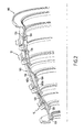
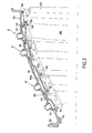
- FIGS 2 and 3 show a turbine stator casing obtained according to the method of the invention.
- This housing supports through its hooks fixing the vanes 200 of the turbine distributor. Enter these blades 200, are located the blades 220 of the rotor of the turbine.
- the first end 12a of the pieces 12 protrudes, so that these pins 12 form bosses can be used as attachment points for various accessories outside the housing.
- the first end 12a of at least one said pins 12 is capable of cooperating, for example by screwing, with the end of a cooling air supply line, not shown in the figures.
- the envelope 105 the casing is cooled by the circulation of fresh air inside the spaces free 110 and 120 traffic paths formed between these spaces free 110.
- all the pieces 12 are intended to be connected to a fresh air supply line so that several air inlets are distributed along the envelope 105. These inputs allow to inject the quantity of fresh air necessary for the good cooling of the casing 105 and their distribution is made so to guarantee the flow of air towards the exit 130.
- the exit 130 is formed by an air circulation path 120 which opens out of the envelope 105.
- the manufacturing method of the invention makes it possible to a turbine stator casing of complex shape, but of structure simple, which has good mechanical properties and which, when operation of the turbine, will be able to be effectively cooled.
Landscapes
- Engineering & Computer Science (AREA)
- Mechanical Engineering (AREA)
- Manufacturing & Machinery (AREA)
- General Engineering & Computer Science (AREA)
- Powder Metallurgy (AREA)
- Turbine Rotor Nozzle Sealing (AREA)
Abstract
Description
- ménager entre les parois des parties d'un moule formé d'au moins deux parties, une cavité de forme correspondant à celle de ladite enveloppe;
- solidariser des noyaux réalisés en un matériau soluble, à l'une desdites parties de moule, au moins, ces noyaux étant maintenus à distance de la paroi de ladite partie et matérialisant des espaces libres que l'on souhaite ménager à l'intérieur de ladite enveloppe ;
- remplir ladite cavité avec une poudre d'un alliage métallique ;
- fritter cette poudre par compression isostatique à chaud ;
- éliminer lesdits noyaux par dissolution ; et
- extraire l'enveloppe ainsi moulée.
- la figure 1 est une coupe axiale partielle d'un exemple d'outillage utilisé pour mettre en oeuvre le procédé de l'invention ;
- la figure 2 est une vue en perspective partielle d'un carter de stator de turbine obtenu selon le procédé de l'invention ;
- la figure 3 est une coupe axiale partielle d'une turbine équipée du carter de la figure 2.
Claims (11)
- Procédé de fabrication d'un carter de stator de turbine, ledit carter comprenant une enveloppe (105), caractérisé en ce qu'il comprend les opérations consistant à :ménager entre les parois des parties (O1, O2, O3, E1, E2) d'un moule formé d'au moins deux parties, une cavité de forme correspondant à celle de ladite enveloppe (105) ;solidariser des noyaux (10), réalisés en un matériau soluble, à au moins une desdites parties de moule (E1), ces noyaux étant maintenus à distance de la paroi de ladite partie de moule et matérialisant des espaces libres (110) que l'on souhaite ménager à l'intérieur de ladite enveloppe (105) ;remplir ladite cavité avec une poudre d'un alliage métallique (24) ;fritter cette poudre (24) par compression isostatique à chaud ;éliminer lesdits noyaux (10) par dissolution ; etextraire l'enveloppe (105) ainsi moulée.
- Procédé selon la revendication 1, caractérisé en ce qu'il comprend les opérations consistant à :mettre en place, entre les noyaux (10), des inserts (20) matérialisant des chemins de circulation (120) entre lesdits espaces libres (110) ; etéliminer ces inserts (20) après l'opération de frittage.
- Procédé selon la revendication 2, caractérisé en ce qu'on réalise lesdits inserts (20) en un matériau soluble et en ce qu'on élimine ces inserts (20) par dissolution.
- Procédé selon l'une quelconque des revendications 1 à 3, caractérisé en ce qu'on utilise des pions tubulaires (12) pour solidariser lesdits noyaux (10) à ladite partie de moule (E1) et en ce qu'on monte une extrémité (12b) de ces pions dans un logement (16) ménagé dans un desdits noyaux (10), et l'autre extrémité (12a) de ces pions dans un logement (14) ménagé dans ladite partie de moule (E1).
- Procédé selon la revendication 4, caractérisé en ce que ladite autre extrémité (12a) d'au moins un desdits pions (12) est susceptible de coopérer avec l'extrémité d'une conduite d'alimentation en air de refroidissement.
- Procédé selon l'une quelconque des revendications 1 à 5, caractérisé en ce qu'on solidarise les pions (12) à l'enveloppe (105) par soudage-diffusion, lors du frittage de la poudre, les matériaux des pions (12) et de l'enveloppe (105) étant compatibles du point de vue du soudage-diffusion.
- Procédé selon l'une quelconque des revendications 1 à 6, ledit carter comprenant, en outre, des crochets de fixation pour soutenir au moins un distributeur de turbine, caractérisé en ce qu'on moule l'enveloppe (105) de manière à ménager sur la face interne de l'enveloppe, tournée vers l'intérieur de la turbine, des projections et en ce qu'on usine ces projections pour leur donner la forme (126) desdits crochets.
- Procédé selon l'une quelconque des revendications 1 à 6, le carter comprenant des crochets de fixation pour soutenir au moins un distributeur de turbine, caractérisé en ce qu'on fabrique ces crochets préalablement au moulage de l'enveloppe (105) et en ce qu'on les fixe ensuite sur la face interne de l'enveloppe, tournée vers l'intérieur du carter.
- Procédé selon la revendication 8, caractérisé en ce qu'on solidarise les crochets à l'enveloppe (105) par soudage-diffusion, lors du frittage de la poudre (24), les matériaux des crochets et de l'enveloppe (105) étant compatibles du point de vue du soudage-diffusion.
- Procédé selon l'une quelconque des revendications 1 à 9, caractérisé en ce qu'on réalise les parties de moule (O1, O2, O3, E1, E2) en matériau soluble et en ce qu'on élimine ces parties de moule par dissolution.
- Procédé selon l'une quelconque des revendications 1 à 10, caractérisé en ce qu'on choisit ledit matériau soluble en acier doux et en ce qu'on utilise de l'acide nitrique comme solvant.
Applications Claiming Priority (2)
| Application Number | Priority Date | Filing Date | Title |
|---|---|---|---|
| FR0406469 | 2004-06-15 | ||
| FR0406469A FR2871398B1 (fr) | 2004-06-15 | 2004-06-15 | Procede de fabrication d'un carter de stator de turbine |
Publications (2)
| Publication Number | Publication Date |
|---|---|
| EP1607158A1 true EP1607158A1 (fr) | 2005-12-21 |
| EP1607158B1 EP1607158B1 (fr) | 2010-01-20 |
Family
ID=34945797
Family Applications (1)
| Application Number | Title | Priority Date | Filing Date |
|---|---|---|---|
| EP05291251A Expired - Lifetime EP1607158B1 (fr) | 2004-06-15 | 2005-06-10 | Procédé de fabrication d'un carter de stator de turbine |
Country Status (6)
| Country | Link |
|---|---|
| US (1) | US7687021B2 (fr) |
| EP (1) | EP1607158B1 (fr) |
| CA (1) | CA2509486C (fr) |
| DE (1) | DE602005018992D1 (fr) |
| FR (1) | FR2871398B1 (fr) |
| RU (1) | RU2377422C2 (fr) |
Cited By (1)
| Publication number | Priority date | Publication date | Assignee | Title |
|---|---|---|---|---|
| EP3228838A1 (fr) * | 2016-03-22 | 2017-10-11 | MTU Aero Engines GmbH | Procédé de fabrication d'un boîtier de turbomachine et boîtier de turbomachine |
Families Citing this family (29)
| Publication number | Priority date | Publication date | Assignee | Title |
|---|---|---|---|---|
| US9114488B2 (en) | 2006-11-21 | 2015-08-25 | Honeywell International Inc. | Superalloy rotor component and method of fabrication |
| US8128865B2 (en) * | 2007-10-31 | 2012-03-06 | Solar Turbines Inc. | Process of making a shrouded impeller |
| US8846206B2 (en) * | 2008-07-31 | 2014-09-30 | Siemens Energy, Inc. | Injection molded component |
| US8303289B2 (en) * | 2009-08-24 | 2012-11-06 | General Electric Company | Device and method for hot isostatic pressing container |
| EP2549066B1 (fr) | 2011-07-19 | 2016-09-14 | General Electric Technology GmbH | Procédé de fabrication d'un carter de turbine |
| US8784037B2 (en) * | 2011-08-31 | 2014-07-22 | Pratt & Whitney Canada Corp. | Turbine shroud segment with integrated impingement plate |
| US8784041B2 (en) * | 2011-08-31 | 2014-07-22 | Pratt & Whitney Canada Corp. | Turbine shroud segment with integrated seal |
| US8784044B2 (en) * | 2011-08-31 | 2014-07-22 | Pratt & Whitney Canada Corp. | Turbine shroud segment |
| US9028744B2 (en) | 2011-08-31 | 2015-05-12 | Pratt & Whitney Canada Corp. | Manufacturing of turbine shroud segment with internal cooling passages |
| US9079245B2 (en) * | 2011-08-31 | 2015-07-14 | Pratt & Whitney Canada Corp. | Turbine shroud segment with inter-segment overlap |
| GB201119240D0 (en) | 2011-11-08 | 2011-12-21 | Rolls Royce Plc | A hot isostatic pressing tool and a method of manufacturing an article from powder material by hot isostatic pressing |
| GB201119238D0 (en) | 2011-11-08 | 2011-12-21 | Rolls Royce Plc | A hot isostatic pressing tool and a method of manufacturing an article from powder material by hot isostatic pressing |
| US9174426B1 (en) * | 2012-03-06 | 2015-11-03 | Florida Turbine Technologies, Inc. | Method of manufacturing a shrouded centrifugal impeller for high speed use |
| US9475118B2 (en) * | 2012-05-01 | 2016-10-25 | United Technologies Corporation | Metal powder casting |
| EP3011139B1 (fr) | 2013-06-17 | 2021-03-31 | Raytheon Technologies Corporation | Composant unitaire et mono-piece de turbine à gaz |
| US9714577B2 (en) | 2013-10-24 | 2017-07-25 | Honeywell International Inc. | Gas turbine engine rotors including intra-hub stress relief features and methods for the manufacture thereof |
| DE102013224982A1 (de) | 2013-12-05 | 2015-06-11 | Rolls-Royce Deutschland Ltd & Co Kg | Fluggasturbine mit einem Kern-Triebwerksgehäuse mit Kühlluftröhren |
| KR101473900B1 (ko) * | 2013-12-18 | 2014-12-18 | 한국항공우주연구원 | 쾌속조형법을 이용한 메탈코어 제작 및 이를 이용한 열간 정수압 성형을 통한 정밀부품 제작 방법 및 이를 이용한 액체로켓 터보펌프 구동용 터빈 블리스크 |
| CN106660125B (zh) * | 2014-05-30 | 2023-03-17 | 诺沃皮尼奥内技术股份有限公司 | 制造涡轮机构件的方法、涡轮机构件和涡轮机 |
| US10040122B2 (en) | 2014-09-22 | 2018-08-07 | Honeywell International Inc. | Methods for producing gas turbine engine rotors and other powdered metal articles having shaped internal cavities |
| JP6563312B2 (ja) * | 2015-11-05 | 2019-08-21 | 川崎重工業株式会社 | ガスタービンエンジンの抽気構造 |
| US10914185B2 (en) * | 2016-12-02 | 2021-02-09 | General Electric Company | Additive manufactured case with internal passages for active clearance control |
| GB201700614D0 (en) * | 2017-01-13 | 2017-03-01 | Rolls Royce Plc | A method of manufacturing a component |
| US11274569B2 (en) | 2017-12-13 | 2022-03-15 | Pratt & Whitney Canada Corp. | Turbine shroud cooling |
| US10570773B2 (en) | 2017-12-13 | 2020-02-25 | Pratt & Whitney Canada Corp. | Turbine shroud cooling |
| US10533454B2 (en) | 2017-12-13 | 2020-01-14 | Pratt & Whitney Canada Corp. | Turbine shroud cooling |
| US10502093B2 (en) * | 2017-12-13 | 2019-12-10 | Pratt & Whitney Canada Corp. | Turbine shroud cooling |
| CN111659891B (zh) * | 2020-07-07 | 2022-03-01 | 西安工业大学 | 一种slm型金属3d打印机的送粉铺粉装置 |
| US11365645B2 (en) | 2020-10-07 | 2022-06-21 | Pratt & Whitney Canada Corp. | Turbine shroud cooling |
Citations (2)
| Publication number | Priority date | Publication date | Assignee | Title |
|---|---|---|---|---|
| US4383854A (en) * | 1980-12-29 | 1983-05-17 | General Electric Company | Method of creating a controlled interior surface configuration of passages within a substrate |
| EP1288444A1 (fr) * | 2001-08-30 | 2003-03-05 | Snecma Moteurs | Attachement des éléments de stator dans le carter d'une turbomachine |
Family Cites Families (12)
| Publication number | Priority date | Publication date | Assignee | Title |
|---|---|---|---|---|
| US4183456A (en) * | 1977-04-06 | 1980-01-15 | General Electric Company | Method of fabricating liquid cooled gas turbine components |
| SU880630A1 (ru) * | 1980-03-31 | 1981-11-15 | Предприятие П/Я Р-6762 | Способ изготовлени спеченных изделий |
| US4604780A (en) * | 1983-02-03 | 1986-08-12 | Solar Turbines Incorporated | Method of fabricating a component having internal cooling passages |
| RU2016701C1 (ru) * | 1991-11-26 | 1994-07-30 | Юрий Михайлович Ермаков | Способ изготовления порошковых изделий с полостями и пресс-форма для его осуществления |
| US5399066A (en) * | 1993-09-30 | 1995-03-21 | General Electric Company | Integral clearance control impingement manifold and environmental shield |
| RU2055697C1 (ru) * | 1994-02-14 | 1996-03-10 | Мурад Керим Оглы Набибеков | Способ изготовления изделий из порошка со сквозными каналами |
| US5875549A (en) * | 1997-03-17 | 1999-03-02 | Siemens Westinghouse Power Corporation | Method of forming internal passages within articles and articles formed by same |
| IT1317538B1 (it) * | 2000-05-15 | 2003-07-09 | Nuovo Pignone Spa | Dispositivo per il controllo dei flussi di refrigerazione delleturbine a gas |
| JP3592664B2 (ja) * | 2001-11-08 | 2004-11-24 | 株式会社東芝 | タービンケーシングの製造方法 |
| US6902371B2 (en) * | 2002-07-26 | 2005-06-07 | General Electric Company | Internal low pressure turbine case cooling |
| US20050000674A1 (en) * | 2003-07-01 | 2005-01-06 | Beddard Thomas Bradley | Perimeter-cooled stage 1 bucket core stabilizing device and related method |
| FR2868467B1 (fr) * | 2004-04-05 | 2006-06-02 | Snecma Moteurs Sa | Carter de turbine a crochets refractaires obtenu par procede mdp |
-
2004
- 2004-06-15 FR FR0406469A patent/FR2871398B1/fr not_active Expired - Fee Related
-
2005
- 2005-06-07 CA CA2509486A patent/CA2509486C/fr not_active Expired - Lifetime
- 2005-06-10 DE DE602005018992T patent/DE602005018992D1/de not_active Expired - Lifetime
- 2005-06-10 EP EP05291251A patent/EP1607158B1/fr not_active Expired - Lifetime
- 2005-06-14 RU RU2005118390/06A patent/RU2377422C2/ru active
- 2005-06-14 US US11/151,427 patent/US7687021B2/en active Active
Patent Citations (2)
| Publication number | Priority date | Publication date | Assignee | Title |
|---|---|---|---|---|
| US4383854A (en) * | 1980-12-29 | 1983-05-17 | General Electric Company | Method of creating a controlled interior surface configuration of passages within a substrate |
| EP1288444A1 (fr) * | 2001-08-30 | 2003-03-05 | Snecma Moteurs | Attachement des éléments de stator dans le carter d'une turbomachine |
Non-Patent Citations (2)
| Title |
|---|
| "High performance and high complexity net shape parts for gas turbines : the ISOPREC powder metallurgy process", MATERIALS AND DESIGN, vol. 21, 2000, pages 345 - 350 |
| R.BACCINO ET AL: "High performance and high complexity net shape parts for gas turbines: the ISOPREC powder metallurgy process", MATERIALS AND DESIGN, vol. 21, 2000, pages 345 - 350, XP008044948 * |
Cited By (2)
| Publication number | Priority date | Publication date | Assignee | Title |
|---|---|---|---|---|
| EP3228838A1 (fr) * | 2016-03-22 | 2017-10-11 | MTU Aero Engines GmbH | Procédé de fabrication d'un boîtier de turbomachine et boîtier de turbomachine |
| US10634008B2 (en) | 2016-03-22 | 2020-04-28 | MTU Aero Engines AG | Method for manufacturing a housing of a turbomachine and turbomachine housing |
Also Published As
| Publication number | Publication date |
|---|---|
| RU2377422C2 (ru) | 2009-12-27 |
| RU2005118390A (ru) | 2006-12-20 |
| CA2509486A1 (fr) | 2005-12-15 |
| US7687021B2 (en) | 2010-03-30 |
| DE602005018992D1 (de) | 2010-03-11 |
| CA2509486C (fr) | 2012-09-04 |
| FR2871398A1 (fr) | 2005-12-16 |
| US20060026833A1 (en) | 2006-02-09 |
| EP1607158B1 (fr) | 2010-01-20 |
| FR2871398B1 (fr) | 2006-09-29 |
Similar Documents
| Publication | Publication Date | Title |
|---|---|---|
| CA2509486C (fr) | Procede de fabrication d'un carter de stator de turbine | |
| CA2500959C (fr) | Carter de turbine a crochets refractaires obtenu par procede mdp | |
| CA2885896C (fr) | Moule carapace a ecran thermique | |
| EP1637253B1 (fr) | Procédé de fabrication d'une aube de turbomachine, assemblage de noyaux pour la mise en oeuvre du procédé | |
| EP2879830B1 (fr) | Procédé de fabrication d'une pièce métallique | |
| EP3218141B1 (fr) | Procédé de soudage par friction avec rechargement d'une pale sur une aube de turbomachine | |
| FR2580967A1 (fr) | Procede pour fabriquer un element composant de turbomachine et element ainsi obtenu | |
| EP2983849B9 (fr) | Moule de fonderie monocristalline | |
| EP0910554B1 (fr) | Fond de filiere a tetons rapportes | |
| EP3134219B1 (fr) | Moule pour fonderie monocristalline | |
| EP2895285B1 (fr) | Modele de fonderie. | |
| WO2011161357A1 (fr) | Noyau pour la fabrication d'une aube de turbine a cavite de bord d'attaque refroidie par impact | |
| EP2906374A2 (fr) | Procédé de fabrication d'au moins une pièce métallique de turbomachine | |
| FR3042725B1 (fr) | Moule pour la fabrication d'une piece par coulee de metal et croissance epitaxiale, et procede correspondant | |
| EP1721698A1 (fr) | Procédé de fabrication d'une aube creuse comportant un sommet en forme de baignoire, procédé de réparation d'une telle aube | |
| FR2995305A1 (fr) | Procede de fabrication ameliore d'un noyau en ceramique destine a la fabrication d'une aube de module de turbomachine | |
| EP2505327A1 (fr) | Procédé de fabrication d'un outillage de moulage destiné au moulage d'une pièce en matériau composite | |
| EP3475012B1 (fr) | Four de refroidissement par solidification dirigée et procédé de refroidissement utilisant un tel four | |
| EP2408578B1 (fr) | Méthode de réalisation d'un carter avec tuyauteries rapportées, carter et son utilisation | |
| EP3657113A1 (fr) | Procédé de réalisation d'un module d'échangeur de chaleur à au moins un circuit de circulation de fluide | |
| FR2876320A1 (fr) | Roue et procede de moulage de roue a valve deportee et masquee | |
| FR3148288A1 (fr) | Four et procede de chauffage ou de prechauffage pour une analyse par tomographie | |
| FR3033720B1 (fr) | Moule de fonderie | |
| FR3098849A1 (fr) | Carter amélioré de module d’aéronef | |
| FR3145890A1 (fr) | Systeme de dissolution de noyaux dans des pieces composites |
Legal Events
| Date | Code | Title | Description |
|---|---|---|---|
| PUAI | Public reference made under article 153(3) epc to a published international application that has entered the european phase |
Free format text: ORIGINAL CODE: 0009012 |
|
| 17P | Request for examination filed |
Effective date: 20050617 |
|
| AK | Designated contracting states |
Kind code of ref document: A1 Designated state(s): AT BE BG CH CY CZ DE DK EE ES FI FR GB GR HU IE IS IT LI LT LU MC NL PL PT RO SE SI SK TR |
|
| AX | Request for extension of the european patent |
Extension state: AL BA HR LV MK YU |
|
| AKX | Designation fees paid |
Designated state(s): DE FR GB |
|
| 17Q | First examination report despatched |
Effective date: 20080911 |
|
| GRAP | Despatch of communication of intention to grant a patent |
Free format text: ORIGINAL CODE: EPIDOSNIGR1 |
|
| GRAC | Information related to communication of intention to grant a patent modified |
Free format text: ORIGINAL CODE: EPIDOSCIGR1 |
|
| GRAS | Grant fee paid |
Free format text: ORIGINAL CODE: EPIDOSNIGR3 |
|
| GRAA | (expected) grant |
Free format text: ORIGINAL CODE: 0009210 |
|
| AK | Designated contracting states |
Kind code of ref document: B1 Designated state(s): DE FR GB |
|
| REG | Reference to a national code |
Ref country code: GB Ref legal event code: FG4D Free format text: NOT ENGLISH |
|
| REF | Corresponds to: |
Ref document number: 602005018992 Country of ref document: DE Date of ref document: 20100311 Kind code of ref document: P |
|
| PLBE | No opposition filed within time limit |
Free format text: ORIGINAL CODE: 0009261 |
|
| STAA | Information on the status of an ep patent application or granted ep patent |
Free format text: STATUS: NO OPPOSITION FILED WITHIN TIME LIMIT |
|
| 26N | No opposition filed |
Effective date: 20101021 |
|
| REG | Reference to a national code |
Ref country code: FR Ref legal event code: PLFP Year of fee payment: 12 |
|
| REG | Reference to a national code |
Ref country code: FR Ref legal event code: PLFP Year of fee payment: 13 |
|
| REG | Reference to a national code |
Ref country code: FR Ref legal event code: PLFP Year of fee payment: 14 |
|
| REG | Reference to a national code |
Ref country code: FR Ref legal event code: CD Owner name: SAFRAN AIRCRAFT ENGINES, FR Effective date: 20170719 |
|
| PGFP | Annual fee paid to national office [announced via postgrant information from national office to epo] |
Ref country code: GB Payment date: 20240521 Year of fee payment: 20 |
|
| PGFP | Annual fee paid to national office [announced via postgrant information from national office to epo] |
Ref country code: DE Payment date: 20240521 Year of fee payment: 20 |
|
| PGFP | Annual fee paid to national office [announced via postgrant information from national office to epo] |
Ref country code: FR Payment date: 20240522 Year of fee payment: 20 |
|
| REG | Reference to a national code |
Ref country code: DE Ref legal event code: R071 Ref document number: 602005018992 Country of ref document: DE |
|
| REG | Reference to a national code |
Ref country code: GB Ref legal event code: PE20 Expiry date: 20250609 |
|
| PG25 | Lapsed in a contracting state [announced via postgrant information from national office to epo] |
Ref country code: GB Free format text: LAPSE BECAUSE OF EXPIRATION OF PROTECTION Effective date: 20250609 |