EP1606513B1 - Submerged water current turbines installed on a deck - Google Patents
Submerged water current turbines installed on a deck Download PDFInfo
- Publication number
- EP1606513B1 EP1606513B1 EP04722894A EP04722894A EP1606513B1 EP 1606513 B1 EP1606513 B1 EP 1606513B1 EP 04722894 A EP04722894 A EP 04722894A EP 04722894 A EP04722894 A EP 04722894A EP 1606513 B1 EP1606513 B1 EP 1606513B1
- Authority
- EP
- European Patent Office
- Prior art keywords
- deck
- platform
- turbine
- water
- flow
- Prior art date
- Legal status (The legal status is an assumption and is not a legal conclusion. Google has not performed a legal analysis and makes no representation as to the accuracy of the status listed.)
- Expired - Lifetime
Links
- XLYOFNOQVPJJNP-UHFFFAOYSA-N water Substances O XLYOFNOQVPJJNP-UHFFFAOYSA-N 0.000 title claims abstract description 118
- 230000000712 assembly Effects 0.000 claims description 10
- 238000000429 assembly Methods 0.000 claims description 10
- 230000000694 effects Effects 0.000 description 18
- 238000012423 maintenance Methods 0.000 description 9
- 230000008439 repair process Effects 0.000 description 7
- 238000000034 method Methods 0.000 description 5
- 230000008901 benefit Effects 0.000 description 3
- 238000006243 chemical reaction Methods 0.000 description 3
- 230000005611 electricity Effects 0.000 description 3
- 239000012530 fluid Substances 0.000 description 3
- 238000004519 manufacturing process Methods 0.000 description 3
- 238000011144 upstream manufacturing Methods 0.000 description 3
- 230000015572 biosynthetic process Effects 0.000 description 2
- 230000000903 blocking effect Effects 0.000 description 2
- 238000010276 construction Methods 0.000 description 2
- 238000005520 cutting process Methods 0.000 description 2
- 230000007423 decrease Effects 0.000 description 2
- 238000011161 development Methods 0.000 description 2
- 238000000605 extraction Methods 0.000 description 2
- 230000009467 reduction Effects 0.000 description 2
- 230000003068 static effect Effects 0.000 description 2
- 241000196324 Embryophyta Species 0.000 description 1
- 230000001133 acceleration Effects 0.000 description 1
- 230000000740 bleeding effect Effects 0.000 description 1
- 230000015556 catabolic process Effects 0.000 description 1
- 125000004122 cyclic group Chemical group 0.000 description 1
- 238000006731 degradation reaction Methods 0.000 description 1
- 238000013461 design Methods 0.000 description 1
- 238000009826 distribution Methods 0.000 description 1
- 230000009189 diving Effects 0.000 description 1
- 230000002708 enhancing effect Effects 0.000 description 1
- 239000000284 extract Substances 0.000 description 1
- 230000004907 flux Effects 0.000 description 1
- 238000009434 installation Methods 0.000 description 1
- 230000002452 interceptive effect Effects 0.000 description 1
- 230000000670 limiting effect Effects 0.000 description 1
- 238000011068 loading method Methods 0.000 description 1
- 230000007246 mechanism Effects 0.000 description 1
- 230000004048 modification Effects 0.000 description 1
- 238000012986 modification Methods 0.000 description 1
- 239000002245 particle Substances 0.000 description 1
- 230000008569 process Effects 0.000 description 1
- 239000000047 product Substances 0.000 description 1
- 230000002829 reductive effect Effects 0.000 description 1
- 230000000717 retained effect Effects 0.000 description 1
- 230000002441 reversible effect Effects 0.000 description 1
- 239000003381 stabilizer Substances 0.000 description 1
- 239000013589 supplement Substances 0.000 description 1
- 238000012546 transfer Methods 0.000 description 1
- 238000004804 winding Methods 0.000 description 1
Images


Classifications
-
- E—FIXED CONSTRUCTIONS
- E02—HYDRAULIC ENGINEERING; FOUNDATIONS; SOIL SHIFTING
- E02B—HYDRAULIC ENGINEERING
- E02B17/00—Artificial islands mounted on piles or like supports, e.g. platforms on raisable legs or offshore constructions; Construction methods therefor
-
- F—MECHANICAL ENGINEERING; LIGHTING; HEATING; WEAPONS; BLASTING
- F03—MACHINES OR ENGINES FOR LIQUIDS; WIND, SPRING, OR WEIGHT MOTORS; PRODUCING MECHANICAL POWER OR A REACTIVE PROPULSIVE THRUST, NOT OTHERWISE PROVIDED FOR
- F03B—MACHINES OR ENGINES FOR LIQUIDS
- F03B17/00—Other machines or engines
- F03B17/06—Other machines or engines using liquid flow with predominantly kinetic energy conversion, e.g. of swinging-flap type, "run-of-river", "ultra-low head"
- F03B17/061—Other machines or engines using liquid flow with predominantly kinetic energy conversion, e.g. of swinging-flap type, "run-of-river", "ultra-low head" with rotation axis substantially in flow direction
-
- E—FIXED CONSTRUCTIONS
- E02—HYDRAULIC ENGINEERING; FOUNDATIONS; SOIL SHIFTING
- E02B—HYDRAULIC ENGINEERING
- E02B17/00—Artificial islands mounted on piles or like supports, e.g. platforms on raisable legs or offshore constructions; Construction methods therefor
- E02B17/0034—Maintenance, repair or inspection of offshore constructions
-
- F—MECHANICAL ENGINEERING; LIGHTING; HEATING; WEAPONS; BLASTING
- F03—MACHINES OR ENGINES FOR LIQUIDS; WIND, SPRING, OR WEIGHT MOTORS; PRODUCING MECHANICAL POWER OR A REACTIVE PROPULSIVE THRUST, NOT OTHERWISE PROVIDED FOR
- F03B—MACHINES OR ENGINES FOR LIQUIDS
- F03B11/00—Parts or details not provided for in, or of interest apart from, the preceding groups, e.g. wear-protection couplings, between turbine and generator
-
- F—MECHANICAL ENGINEERING; LIGHTING; HEATING; WEAPONS; BLASTING
- F03—MACHINES OR ENGINES FOR LIQUIDS; WIND, SPRING, OR WEIGHT MOTORS; PRODUCING MECHANICAL POWER OR A REACTIVE PROPULSIVE THRUST, NOT OTHERWISE PROVIDED FOR
- F03B—MACHINES OR ENGINES FOR LIQUIDS
- F03B13/00—Adaptations of machines or engines for special use; Combinations of machines or engines with driving or driven apparatus; Power stations or aggregates
- F03B13/12—Adaptations of machines or engines for special use; Combinations of machines or engines with driving or driven apparatus; Power stations or aggregates characterised by using wave or tide energy
- F03B13/26—Adaptations of machines or engines for special use; Combinations of machines or engines with driving or driven apparatus; Power stations or aggregates characterised by using wave or tide energy using tide energy
- F03B13/264—Adaptations of machines or engines for special use; Combinations of machines or engines with driving or driven apparatus; Power stations or aggregates characterised by using wave or tide energy using tide energy using the horizontal flow of water resulting from tide movement
-
- E—FIXED CONSTRUCTIONS
- E02—HYDRAULIC ENGINEERING; FOUNDATIONS; SOIL SHIFTING
- E02B—HYDRAULIC ENGINEERING
- E02B17/00—Artificial islands mounted on piles or like supports, e.g. platforms on raisable legs or offshore constructions; Construction methods therefor
- E02B2017/0091—Offshore structures for wind turbines
-
- F—MECHANICAL ENGINEERING; LIGHTING; HEATING; WEAPONS; BLASTING
- F05—INDEXING SCHEMES RELATING TO ENGINES OR PUMPS IN VARIOUS SUBCLASSES OF CLASSES F01-F04
- F05B—INDEXING SCHEME RELATING TO WIND, SPRING, WEIGHT, INERTIA OR LIKE MOTORS, TO MACHINES OR ENGINES FOR LIQUIDS COVERED BY SUBCLASSES F03B, F03D AND F03G
- F05B2240/00—Components
- F05B2240/40—Use of a multiplicity of similar components
-
- F—MECHANICAL ENGINEERING; LIGHTING; HEATING; WEAPONS; BLASTING
- F05—INDEXING SCHEMES RELATING TO ENGINES OR PUMPS IN VARIOUS SUBCLASSES OF CLASSES F01-F04
- F05B—INDEXING SCHEME RELATING TO WIND, SPRING, WEIGHT, INERTIA OR LIKE MOTORS, TO MACHINES OR ENGINES FOR LIQUIDS COVERED BY SUBCLASSES F03B, F03D AND F03G
- F05B2240/00—Components
- F05B2240/90—Mounting on supporting structures or systems
- F05B2240/97—Mounting on supporting structures or systems on a submerged structure
-
- Y—GENERAL TAGGING OF NEW TECHNOLOGICAL DEVELOPMENTS; GENERAL TAGGING OF CROSS-SECTIONAL TECHNOLOGIES SPANNING OVER SEVERAL SECTIONS OF THE IPC; TECHNICAL SUBJECTS COVERED BY FORMER USPC CROSS-REFERENCE ART COLLECTIONS [XRACs] AND DIGESTS
- Y02—TECHNOLOGIES OR APPLICATIONS FOR MITIGATION OR ADAPTATION AGAINST CLIMATE CHANGE
- Y02E—REDUCTION OF GREENHOUSE GAS [GHG] EMISSIONS, RELATED TO ENERGY GENERATION, TRANSMISSION OR DISTRIBUTION
- Y02E10/00—Energy generation through renewable energy sources
- Y02E10/20—Hydro energy
-
- Y—GENERAL TAGGING OF NEW TECHNOLOGICAL DEVELOPMENTS; GENERAL TAGGING OF CROSS-SECTIONAL TECHNOLOGIES SPANNING OVER SEVERAL SECTIONS OF THE IPC; TECHNICAL SUBJECTS COVERED BY FORMER USPC CROSS-REFERENCE ART COLLECTIONS [XRACs] AND DIGESTS
- Y02—TECHNOLOGIES OR APPLICATIONS FOR MITIGATION OR ADAPTATION AGAINST CLIMATE CHANGE
- Y02E—REDUCTION OF GREENHOUSE GAS [GHG] EMISSIONS, RELATED TO ENERGY GENERATION, TRANSMISSION OR DISTRIBUTION
- Y02E10/00—Energy generation through renewable energy sources
- Y02E10/30—Energy from the sea, e.g. using wave energy or salinity gradient
-
- Y—GENERAL TAGGING OF NEW TECHNOLOGICAL DEVELOPMENTS; GENERAL TAGGING OF CROSS-SECTIONAL TECHNOLOGIES SPANNING OVER SEVERAL SECTIONS OF THE IPC; TECHNICAL SUBJECTS COVERED BY FORMER USPC CROSS-REFERENCE ART COLLECTIONS [XRACs] AND DIGESTS
- Y02—TECHNOLOGIES OR APPLICATIONS FOR MITIGATION OR ADAPTATION AGAINST CLIMATE CHANGE
- Y02P—CLIMATE CHANGE MITIGATION TECHNOLOGIES IN THE PRODUCTION OR PROCESSING OF GOODS
- Y02P70/00—Climate change mitigation technologies in the production process for final industrial or consumer products
- Y02P70/50—Manufacturing or production processes characterised by the final manufactured product
Definitions
- This invention relates to structures for the support of turbines arranged to be immersed in a water current and driven by the kinetic energy of the flow of water.
- EP 0708241 A3 illustrates the use of a square permanently submerged platform supported upon vertical columns one to each corner of the platform.
- the columns are mounted from the sea bed.
- the platform mounts a number of turbines that are housed totally beneath the platform by way of supports which allow for positional adjustment of the location of the turbines beneath the platform.
- Example International Application No WO 99/02853 disclosed the use of an elongate support submerged in a flow of water and carrying a plurality of water wheels projecting above and below the elongate support the latter being anchored by cables so that the support is horizontal and crossways on to the flow of water.
- United States Patent No 1,560,309 discloses a water current motor assembly which is supportable by floats in a flow of water or which rests upon the bed of a flow of water which assembly includes a floor and walls defining a channel through which the water is arranged to flow. Water wheels are mounted between the walls and supported from the floor. The channel is provided at each end with a mouth having converging walls leading to a circular inlets substantially corresponding in size to the diameter of the water whose peripheries are above floor level for water that is to flow via the channel through the water, wheels. Each mouth is provided with a screen to prevent weeds or debris from becoming entangled with the water wheels.
- An object of the invention is to provide support structures, referred to herein as "False Sea beds” for the specific purpose of supporting water current turbines (in the sea, a river or an estuary as the case may be).
- rotors of any known type capable of being driven by flowing water in a manner by which they can drive a generator for the production of electricity or for some other useful application such as a pump or compressor could be applied with this invention whereby a further object of the invention is the provision of support structures suitable for supporting for example rotor(s) that may generally be of the following types:
- the turbine hydrofoils of whichever kind, rotate or reciprocate (as the case may be) entirely within the water column of flowing currents, whether they be at sea, in rivers or in estuaries, and which in various ways to be described meet the aforementioned requirements. In other words the active components remain completely submerged throughout their normal mode of operation.
- a further important object of this invention is to provide means by which the rotors and other moving parts, such as the power train, can be raised clearly above the surface of the water to permit safe and effective access from a surface vessel for installation, maintenance, repairs and replacement of said components.
- any such turbine is additionally exposed to numerous cyclic loads caused by phenomena such as the effects of turbulence, passing waves, velocity shear in the water column (i.e. variation in velocity with depth) and vortex shedding, which will impose fluctuating fatigue loadings on any support structure that need to be allowed for in providing adequate structural integrity. Therefore, an essential requirement for any such turbine is for the rotor which extracts the energy to be held in position by a structure with adequate reserves of strength to resist the static and also the dynamic forces imposed on the rotor.
- the structure needs to be configured such that its wake ideally completely misses the rotor; the structure should also be as economical as possible to manufacture in order to minimise the costs of the system; there needs to be some practical and cost-effective method for installing the structure in a location with strong currents; and there needs to be some practical and cost-effective-method for installing the turbine rotor or rotors onto the structure and then for gaining access to the rotor or rotors in order to maintain and when necessary to replace or repair them.
- the flow in the water column at locations with high enough velocities to be suitable for the use of energy capturing turbines varies with depth such that the maximum velocity tends to be near to the surface.
- the currents low in the water column, near the sea (or estuary or river) bed move much more slowly.
- any uneven natural features in the sea, river or estuary bed will cause disruption of the flow near the seabed and turbulence; the more uneven and rougher the nature of the bed, the greater will be the thickness of a slow moving and turbulent boundary layer.
- any device immersed in the currents in a water column (whether in the sea, a river or an estuary) will need to be accessed occasionally for maintenance, repairs or replacement.
- Underwater operations in fast flowing currents whether by human personnel wearing diving equipment or whether by remotely operated underwater vehicles (ROVs), are extremely difficult as most such activities could only be undertaken at times when water flows of less than about 0.5m/s occur, and in a good energetic location for water current energy exploitation, the duration of periods with such low velocities is at best too short to permit more than the most minor of underwater operations.
- ROVs remotely operated underwater vehicles
- a problem to be addressed by this invention is the provision of means for accessing components needing maintenance or repair, in particular the turbine rotor(s) and/or hydrofoils together with the mechanical drive train and generator which they activate, by making it possible to raise said items above the surface of the flowing water current so that access from a surface vessel is possible and no underwater intervention by divers or remotely operated submersible vehicles is needed.
- rotors of any known type capable of being driven by flowing water in a manner by which they can drive a generator for the production of electricity or for some other useful application such as a pump or compressor could be applied with this invention whereby a further object of the invention is the provision o fthe turbine rotor(s) and/or hydrofoils together with the mechanical drive train and generator which they activate, by making it possible to raise said items above the surface of the flowing water current so that access from a surface vessel is possible and no underwater intervention by divers or remotely submersible vehicles is needed.
- a flowing-water drivable turbine system including a supporting structure including a deck or platform (1) with elongate edge regions locatable at an elevated horizontal position with respect to the bed (SB) of the flowing water by deck or platform support means anchored to the bed (SB) of the flowing water with its elongate edge regions extending transverse to the direction of the flowing water, the deck or platform serving to mount an upstanding turbine assembly or a plurality of turbine assemblies (3) in the flowing water for operational co-operation with the flow of water, characterised in that the deck or platform (1) is of a streamlined cross section with the elongate edge regions thereof rounded, in that the turbine assembly or turbines assemblies (3) is/are so mountable to the deck or platform (1), in that the turbine assembly or turbines assemblies and their associated rotors are located totally above the upper surface of the deck or platform (1), in that the deck or platform is so horizontally positioned relative to the bed (SB) as to produce a space between the bed and the under
- These extra surfaces may be added as a parallel surface to the main supporting surface either at the level of the turbine rotor axes or above the level of the turbine rotors or both of these options.
- said extra surfaces may preferably be smaller in chord and in thickness than the lowermost supporting surface but they may also be equal sized or larger
- the first mentioned deck or platform of streamlined cross section has an asymmetrical streamlined cross section in which there is a greater convexity on one surface compared with the other to the extent that upper and lower surfaces are be convex, with one more so than the other.
- the rectangular planformed deck or platform of streamlined cross-section to be either released from its supports and rise to the surface using buoyancy in a controlled manner or to have some lift mechanism which may generally be electrically or hydraulically activated, so that there is the facility for the entire rectangular planformed deck or platform of streamlined cross-section complete with the array of turbines to reach the water surface so that the turbines may be accessed for maintenance or repairs using surface vessels.
- the rectangular planformed deck or platform of streamlined cross-section has an asymmetrical streamlined cross section in which there is greater convexity on one surface compared with the other, to the extent that both surfaces (upper and lower may be convex, one more so than the other) or one surface (upper or lower) is convex and the other is either substantially flat or concave.
- both surfaces upper and lower may be convex, one more so than the other
- one surface upper or lower
- the other is either substantially flat or concave.
- the effect of this will be to accelerate the flow over the more convex surface in a manner designed to reduce velocity shear through the rotor (velocity shear is the tendency for water in the upper part of a current to move faster than water nearer to the seabed.
- the formation of said surfaces is such that the accelerated flow over the more convex surface serves to enhance the performance of the turbines in the case where the greater convexity is in the upper surface.
- the deck or platform provides a planar smooth surface of a generally rectangular platform, (i.e. when viewed from directly above) with adequate structural integrity as not to flex unduly, deployed like a deck or bridge in the water column such that it forms a floor to support one or more, generally a row of, turbines the arrangement being such that the surface performs like a "false seabed” having a smooth surface to enhance the eveness of flow over it as compared with the water flow over most real sea beds.
- This surface can either be supported on weight bearing struts like legs so that it sits on the bed of the sea, river or estuary much like a table standing on a plurality of legs, or it can be buoyant and held in the water column by a plurality of tensioned cables attached to the bed of the sea, river or estuary using suitable ground anchors much like a rectangular tension buoy tethered to float low in the water column.
- the planar smooth surface will generally be rectangular in plan view and the longer dimension will be sufficient to accommodate the overall width of however many individual turbines may be attached to its upper surface. Moreover the longer dimension will generally be set normal to the direction of flow of the currents so that the turbines which will be attached to its upper surface are arranged laterally across the current with the operational profile of all the rotors normal to the flow so as to intercept as much of the flow as possible. In effect the structure will resemble a rectangular planform "wing" suspended in the water column with a row of turbines arranged above it.
- the cross section or profile of the rectangular surface or deck is to be streamlined for two reasons, namely to minimise the drag it will experience from the passing current and also to assist in orientating the flow in such a way as to minimise turbulence in the flow passing over the top of the surface and through the rotors.
- leading and trailing edges of the profile with respect to the flow of water will be tapered either to a sharp edge or to a narrow but rounded edge much like the leading edge of the wing or an aircraft or the hydrovane of a submarine or ship stabiliser.
- the surface will be symmetrical in cross section such that it exhibits low drag whether the flow is in one direction or in the reverse direction.
- planar smooth rectangular surface or deck so as to enhance the velocity of flow passing through the rotor(s) mounted above its upper surface and to improve the uniformity of flow through the rotors.
- the surface or deck act as a structure to carry the turbine rotor(s) but it will also be designed so as to improve the uniformity and possibly the velocity of the flow through the rotor(s) which will enhance their performance and efficiency compared with operation in unmodified flow.
- the cross section of the rectangular planar surface or deck may (in some but not all cases) also be asymmetrical or cambered in cross section (i.e. convex on one side and possibly concave, flat or at least less convex on the other) in such a way that it generates a lift force perpendicular to the current much the same way as an airfoil or hydrofoil.
- said asymmetry could be arranged so as to generate a vertically downward lift force to improve the engagement of the legs with the sea, river or estuarial bed but in the case where the surface or deck is buoyant and held down by tensioned moorings, then the profile or cross section would be asymmetrical so as to create a vertically upwards acting lift force to increase the tension in the supporting cables as the current increases and thereby to stabilise the structure in the water column and avoid it being displaced unduly by the thrust from the current.
- the support structure of the invention therefore resembles a wing-like arrangement with turbines mounted above it such that their rotor(s) or driven hydrofoils are set in a horizontal row normal to the flow of the current.
- Said wing may be symmetrical and streamlined and supported on a plurality of legs or struts, or it may be buoyant and held by tensioned cables or members securely anchored to the bed of the sea, river or estuary.
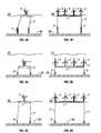
- FIGS. 1A, 1B and 1C respectively show in schematic isometric, side and end elevations respectively the major elements of a first embodiment of a support structure incorporating the concepts of the invention, namely a platform or deck 1 fixed in place by, for example, a plurality of legs 2 upstanding from a river, estuary or sea bed SB and carrying a number of water current driven turbines (3) arranged in a row normal to the direction of flow DF of the current. past the turbines.
- the Figures illustrate the use of four axial flow turbines, 3 but some other number may be used. Furthermore, various types of and different types of turbine may be used as previously mentioned.
- the turbines 3 are supported on individual cantilevered, streamlined supporting struts 4 above discussed.
- the direction of water flows DF is indicated by the double ended arrow so as to indicate bi-directional water flow possibilities
- the second set of planar horizontal members between each turbine, parallel to and above a main supporting surface or deck already described in such a way that the structure resembles a biplane's wing arrangement; the second set of planar members will also be streamlined and will generally (but not necessarily) be of smaller cross-sectional dimensions than the main wing-like supporting deck.
- Blocking the space below the supporting surface so that water is partly inhibited from flowing beneath it has the effect of further accelerating the flow of water over the top of the planar surface and through the turbine rotor(s) thereby enhancing the power gained by the system.
- By blocking most of the space between the seabed and the underside of the planar surface, but leaving a relatively vertically narrow passage immediately below the planar surface so as to allow a clean flow immediately below it has the effect that any turbulent boundary layer flowing above the sea, river or estuarial bed may be bled under the planar surface through the aforementioned space in order to keep the flow over the top as free of turbulence as possible.
- a biplane or triplane arrangement there can be one, two or three streamlined planar surfaces arranged in a horizontal plane across the flow of the current in a "monoplane", "biplane” or “triplane” arrangement.
- the advantages and purpose of a biplane or triplane arrangement are partly to improve the structural strength and also partly to shape the streamlined wing like members so that the flow through the turbine rotor(s) is both rendered more uniform (i.e. with less velocity shear across the vertical height of the rotors) and in some cases may be accelerated so that the supporting wings also effectively act as flow augmentors which increase the energy flux through the given cross-section of the rotor(s).
- a main aspect of this invention is the use of a streamlined planar surface or deck fixed in the water column so as to carry a row of water current powered turbines arranged across the direction of flow, such that the streamlined planar surface acts as a structural support for the water current turbine(s), it can also be made buoyant such that it can float to the surface permitting access to the turbine(s) arranged on its upper surface.
- the shape of the streamlined planar surface is such that it improves the uniformity of the flow through the turbine rotor(s) and may in some cases increase the local velocity through the rotor(s) so as to improve the energy capture for a given area of rotor.
- FIGS 2A and 2B illustrate a side/end and front elevation how the platform or deck 1 such as shown in Figure 1 may be allowed to rise to the surface, by making it buoyant and, for example, by paying out cables, chains or ropes 5 from each corner, these being securely attached to the foundation supports 2.
- This process can be reversed by drawing the platform or deck 1 down by winding in the cables, chains or ropes 5 until the deck 1 is back in contact with the seabed mounted supports 2.
- An essential component of this embodiment of the support structure is that the platform or deck 1 carrying the turbines 3 can be in some way allowed to rise (or be lifted mechanically) to the surface to permit access to the turbines for maintenance, repairs or replacement without the need for underwater intervention.
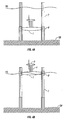
- Figures 3A, 3B, 3C and 3D show in end/side and front elevation an embodiment of a support structure that can be regarded as a variation of the embodiment of Figures 1A 1B and 1C variation where the deck of platform 1 is maintained in a permanently buoyant state and held in place both when submerged and when on the surface by extendible tension moorings 5 attached to suitable fixings 6, embedded or anchored in the sea or river bed, which must be capable of resisting the uplift forces involved.
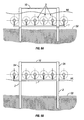
- FIGS 4A, 4B and Figures 5A, 5B show (in side elevation and in front elevation respectively) a further embodiment of a support structure where instead of using extendible flexible chains, cables or ropes, the platform 1 is constrained to two, four (as illustrated) (or some other plurality) of legs 7 which are embedded in the sea or river bed SB and which extend above the surface level WL of the water, in such a manner that the legs guide the vertical movement of the platform or deck carrying the turbine(s) by way of suitable sliding sleeves or other fixings 8 capable of moving vertically with respect to the legs 7 and constrained to follow said legs.
- the upper part of the legs 7 that guide the vertical movement of the platform or deck carrying the turbines can optionally be narrowed to reduce their drag in the current as shown (so the cross section of the upper part of the leg viewed in plan resembles an ellipse). It should also be noted that the legs are positioned between the rotors of the turbines so that their wakes when the current is flowing do not impinge on the rotors or at least the interference between rotors and wakes is minimised. This is the preferred arrangement as clearly indicated in Figures 5A and 5B .
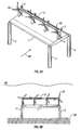
- FIGs 6A and 6B are respectively an isometric view and an elevation viewed from the direction of flow WF of the water of an arrangement of the "biplane" type where a second wing-like platform or deck 9 is introduced between the turbines 3 at the level of the centre line of the rotors 3A of the turbines in order to improve the structural strength of the assembly.
- This arrangement should be compared with the "monoplane" arrangement of the isometric view in Figure 1A where the individual turbine rotors are mounted on individual cantilevered support struts with no lateral bracing.
- Figures 7A illustrates an alternative "biplane" arrangement where a second streamlined planar platform 10 is installed immediately above the turbines on extensions 11 to their vertical support struts 4.
- Figure 7A is an isometric perspective while the Figures 7B and 7C respectively show an end/side elevation and a front elevation as viewed from the direction of flow WF of the current.
- This arrangement serves to increase the structural strength of the entire assembly and may permit it to span a greater distance between its supports 2 so as to accommodate either a greater number of turbines or larger sized turbines 3.
- the effect of the upwardly facing convex surface of the lower supporting platform 1 and the downwardly facing convex surface of the upper platform 10 will be similar to that of a venturi (see the side elevation view of Figure 7B ) and will cause the flow through the rotors to be accelerated compared with the flow further upstream of the rotors. This will improve the energy captured per unit area of rotors, allowing smaller rotors to be used for a given power output than would otherwise be needed.
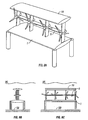
- Figures 8A, 8B and 8C can conveniently be regarded as an embodiment of a support structure combining the proposals of Figures 6 and Figures 7 , and it is in effect a "triplane" arrangement with three wing-like platforms, a supporting platform 1, an intermediate platform 9 at the level of the turbine rotors 3A (as in Figures 6A, 6B and 6C) and an upper platform 10 (as in Figures 7A, 7B and 7C ).
- the main advantage of this arrangement is greater structural strength, but at the cost of extra drag and greater wake interference with the rotors. However the aforementioned venturi effect will compensate for this.
- the upper platform 10 will generally (but not necessarily) be smaller in chord length and cross-section than the lower supporting platform 1 as the preferred embodiment, substantially as is shown in the various Figures 7A, 7B, 7C and Figures 8A, 8B and 8C .
- FIGS 9A and 9B schematically illustrate an embodiment including a single planar surface or deck 1 carried by supports 2 involving lifting columns 2A the same principle might equally be applied to configurations with "biplane” or “triplane” arrangements such are shown as in the groups of Figures 6 , 7 and 8 .
- Figure 9A (in elevation when viewed from the direction WF of the current), schematically shows the support platform/deck system 1 lowered and operational, whilst Figure 9B illustrates the platform/deck system raised to the surface for maintenance.
- Figures indicates an arrangement in which a planar surface, platform or deck 1 can carry a plurality of turbines 3 and in this case it is supported in such a way that it does not necessarily rely on buoyancy to lift it, but mechanical means are provided through the use of hydraulic rams or electric jacks or winches (not shown) to lift the entire deck assembly complete with its array of turbines to the surface. Buoyancy of the platform 1 may be used to supplement the lift and thereby reduce the lifting forces needed.
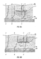
- Figures 10A and 10B are cross-sectional schematic views through the main supporting platform or deck 1 of figure 1 or figure 6 (and as shown in all the other preceding figures).
- the supporting platform or deck was shown as having a symmetrical, streamlined elliptical cross-section or profile
- the example in Figure 10A has an optional asymmetrical cross-section in which it is more convex on the lower side than on the upper side.
- the upper side may be slightly concave as in the illustration, but the same principle will apply if the upper side is either flat or less convex than the lower side.
- Figure 10B shows an asymmetrical cross-sectioned platform or deck in which the upper side is more convex than the lower side.
- Figure 10A and Figure 10B illustrate the flow of water above and below the platform and deck in the form of streamlines that would be followed by any particle in the flowing water column.
- the flow profile or velocity gradient through the water column is typical of the unimpeded current in a tidal stream, the sea, a river or an estuary, where the fastest flowing water is in the upper 50% of the flow and where generally an exponential degradation in velocity occurs in the lower 50% of the flow, reaching zero where the water is in direct contact with the bed (velocity being indicated in the figure by the length of the arrows where each streamline crosses the cross-section in question).
- the velocity profile through the water column shown at profile "BB” illustrates how the water is already influenced by the presence of the obstruction caused by the shaped platform ; water flow will start to deflect upstream of any obstruction.
- the velocity profiles at “CC” show the approximate velocity distribution immediately above and below the platform or deck in the position where the turbines (3) are located. In effect, the profiles at "BB” are intermediate between those for "AA” and "CC".
- FIGS. 10A and 10B show the well known effect that is developed from the laws of continuity in fluid dynamics, that flow will accelerate if it needs to follow -a longer path or if the cross section through which it flows smoothly decreases, and vice-versa.
- the streamlines are squeezed together and the flow accelerates over the more convex side of an asymmetrical streamlined platform or deck and the flow decelerates and the streamlines tend to be spread wider apart on the less convex or the concave side.
- This is in fact similar to the flow past a wing or hydrofoil and the accompanying effect which is also well known is the fast moving fluid causes a reduction in pressure while the slower moving fluid causes a relative increase in pressure.
- the resulting pressure difference across the streamlined platform is similar to the effect of a hydrofoil or wing and generates a force at right angles to the direction of flow, which is effectively a Lift force, marked as “L” in Figures 10A and 10B .
- a drag force "D”, much smaller than the lift force "L” will also be generated in the direction of flow.
- Figures 10A and 10B both show that the effect of the asymmetrically shaped supporting platform or deck is to produce a relatively uniform flow over its upper surface, which will be slightly accelerated compared with the free stream situation (as shown at position "AA") in the case where the most convex side is uppermost (as in Figure 10B ) and slightly decelerated compared with the free-stream situation when the most convex side is downwards (as in Figure 10A ).
- the boundary layer is caused by turbulence where the flow interacts with the sea or river bed, and in some cases if this is uneven or lacking in uniformity the boundary layer can be quite thick and could cause loss of performance and possible damage to the bottom of turbine rotors if they were to penetrate this area of highly disturbed flow.
- the lift forces generated by the asymmetrical supporting platform or deck may be used to improve its stability; in the case of Figure WA the platform could be placed on compressive supports (or legs) and the downwardly directed force L will in effect provide extra down thrust to hold the platform securely onto the supports.
- the supporting platform or deck might be buoyant and retained in position by tensioned moorings and the lift force acting upwards will tend to stabilise the platform by adding to buoyancy effects needed to maintain the tension in the moorings. Since both the lift and the drag forces will be proportionate to the square of the velocity of the current they will tend to stabilise the system with significantly greater forces in stronger currents, and the lift and drag components will tend to stay proportionate.
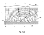
- Figure 10C shows a modification of the embodiment given in Figure 10B , where the space below the support deck or platform is additionally and almost completely blocked by an obstruction provided for this purpose and marked (XX) leaving a slot or slots (12) for the passage of water. It can be seen that the effect of this obstruction (XX) is to force most of the flowing water column at point (AA) to rise and squeeze through a reduced height of water column at (CC) where the turbine rotors are deployed.
- the shape of the convex upper side of the platform is such that the flow over the top is uniform and accelerated.
- the provision of the slot or slots (12) located above the obstruction (XX) and immediately below the deck or platform primarily serves to prevent the turbulent boundary layer from interfering with the water flow over the top of the deck or platform; basically the small flow leaking underneath limiting the height of the boundary layer by bleeding part of the main smoothly flowing stream below the platform.
Landscapes
- Engineering & Computer Science (AREA)
- General Engineering & Computer Science (AREA)
- Mechanical Engineering (AREA)
- Chemical & Material Sciences (AREA)
- Combustion & Propulsion (AREA)
- Power Engineering (AREA)
- Civil Engineering (AREA)
- Structural Engineering (AREA)
- Life Sciences & Earth Sciences (AREA)
- General Life Sciences & Earth Sciences (AREA)
- Oceanography (AREA)
- Other Liquid Machine Or Engine Such As Wave Power Use (AREA)
- Hydraulic Turbines (AREA)
- Earth Drilling (AREA)
- Motor Or Generator Frames (AREA)
Applications Claiming Priority (3)
| Application Number | Priority Date | Filing Date | Title |
|---|---|---|---|
| GB3036809 | 2003-03-25 | ||
| GBGB0306809.5A GB0306809D0 (en) | 2003-03-25 | 2003-03-25 | Water current powered turbines installed on a deck or "false seabed" |
| PCT/GB2004/001284 WO2004085845A1 (en) | 2003-03-25 | 2004-03-24 | Submerged water current turbines installed on a deck |
Publications (2)
| Publication Number | Publication Date |
|---|---|
| EP1606513A1 EP1606513A1 (en) | 2005-12-21 |
| EP1606513B1 true EP1606513B1 (en) | 2011-08-17 |
Family
ID=9955473
Family Applications (1)
| Application Number | Title | Priority Date | Filing Date |
|---|---|---|---|
| EP04722894A Expired - Lifetime EP1606513B1 (en) | 2003-03-25 | 2004-03-24 | Submerged water current turbines installed on a deck |
Country Status (12)
| Country | Link |
|---|---|
| US (2) | US7331762B2 (zh) |
| EP (1) | EP1606513B1 (zh) |
| JP (1) | JP4732334B2 (zh) |
| CN (1) | CN1764781B (zh) |
| AT (1) | ATE520878T1 (zh) |
| AU (1) | AU2004223640B2 (zh) |
| CA (1) | CA2517729C (zh) |
| DE (1) | DE602004032220D1 (zh) |
| GB (2) | GB0306809D0 (zh) |
| NZ (1) | NZ542386A (zh) |
| RU (1) | RU2349791C2 (zh) |
| WO (1) | WO2004085845A1 (zh) |
Families Citing this family (95)
| Publication number | Priority date | Publication date | Assignee | Title |
|---|---|---|---|---|
| ES2240768T3 (es) * | 2001-07-11 | 2005-10-16 | Hydra Tidal Energy Technology As | Instalacion que permite generar energia a partir de corrientes de agua. |
| US6860219B1 (en) * | 2003-03-17 | 2005-03-01 | Harry Edward Dempster | Technique and platform for fabricating a variable-buoyancy structure |
| GB0329589D0 (en) * | 2003-12-20 | 2004-01-28 | Marine Current Turbines Ltd | Articulated false sea bed |
| US7352078B2 (en) * | 2005-05-19 | 2008-04-01 | Donald Hollis Gehring | Offshore power generator with current, wave or alternative generators |
| US7397144B1 (en) * | 2005-06-15 | 2008-07-08 | Florida Turbine Technologies, Inc. | Bearing-less floating wind turbine |
| GB2431628B (en) * | 2005-10-31 | 2009-01-28 | Tidal Generation Ltd | A deployment and retrieval apparatus for submerged power generating devices |
| US20070134094A1 (en) * | 2005-12-08 | 2007-06-14 | Stephen Gregory | Rotor apparatus and turbine system incorporating same |
| GB0600942D0 (en) * | 2006-01-18 | 2006-02-22 | Marine Current Turbines Ltd | Improvements in gravity foundations for tidal stream turbines |
| US20070236020A1 (en) * | 2006-04-06 | 2007-10-11 | Ahearn John M | System for generation electric power |
| WO2008062319A2 (en) * | 2006-07-10 | 2008-05-29 | Justin Clive Roe | Marine energy hybrid |
| DE102006033215B4 (de) * | 2006-07-13 | 2008-11-06 | They, Jan, Dr. | Vorrichtung zur stabilen Lagerung von Anlagen oder Bauwerken auf See |
| US20080018115A1 (en) * | 2006-07-20 | 2008-01-24 | Boray Technologies, Inc. | Semi-submersible hydroelectric power plant |
| US7816802B2 (en) * | 2006-10-06 | 2010-10-19 | William M Green | Electricity generating assembly |
| US7492054B2 (en) * | 2006-10-24 | 2009-02-17 | Catlin Christopher S | River and tidal power harvester |
| ITMI20070489A1 (it) * | 2007-03-12 | 2008-09-13 | Josef Gostner | Sistema per la generazione di energia elettrica |
| GB0704897D0 (en) * | 2007-03-14 | 2007-04-18 | Rotech Holdings Ltd | Power generator and turbine unit |
| EP1992741A1 (en) * | 2007-04-11 | 2008-11-19 | OpenHydro Group Limited | A system and method for the deployment of a hydroelectric turbine |
| US8102071B2 (en) * | 2007-10-18 | 2012-01-24 | Catlin Christopher S | River and tidal power harvester |
| JP4982827B2 (ja) * | 2007-11-08 | 2012-07-25 | 独立行政法人海上技術安全研究所 | 潮流・海流発電装置 |
| GB2455784B (en) | 2007-12-21 | 2012-10-24 | Tidal Energy Ltd | Tidal flow power generation |
| WO2009088302A2 (en) * | 2008-01-11 | 2009-07-16 | Prima Ocean As | Apparatus and method for supporting equipment units in a body of water |
| JP4982828B2 (ja) * | 2008-01-23 | 2012-07-25 | 独立行政法人海上技術安全研究所 | 潮流・海流発電装置 |
| US7994649B2 (en) * | 2008-04-23 | 2011-08-09 | Abatemarco Michael R | Pelagic sustainable energy system |
| GB2461265A (en) * | 2008-06-23 | 2009-12-30 | Tidal Energy Ltd | Tidal turbine with limited axial thrust |
| US7851936B2 (en) * | 2008-07-16 | 2010-12-14 | Anadarko Petroleum Corporation | Water current power generation system |
| EP2318693B1 (en) * | 2008-07-16 | 2015-09-09 | New Energy Corporation Inc. | Torque neutralizing turbine mooring system |
| GB2462257B (en) * | 2008-07-29 | 2010-09-29 | Clean Current Power Systems | Electrical machine with dual insulated coil assembly |
| GB2462320B (en) * | 2008-08-05 | 2013-02-20 | Pulse Group Holdings Ltd | An apparatus for generating power from a fluid stream |
| RU2378531C1 (ru) * | 2008-08-06 | 2010-01-10 | Виктор Михайлович Лятхер | Энергоустановка для преобразования энергии течения воздушных и водных потоков |
| US8624836B1 (en) | 2008-10-24 | 2014-01-07 | Google Inc. | Gesture-based small device input |
| CH699791A2 (it) * | 2008-10-24 | 2010-04-30 | Vittorio Perregrini | Dispositivo generatore integrato per la produzione di energia da fonti alternative rinnovabili ad emissioni zero nel rispetto e protezione ambientale. |
| ATE536304T1 (de) * | 2008-12-18 | 2011-12-15 | Openhydro Ip Ltd | Stützsystem für eine hydroelektrische turbine |
| US8651798B2 (en) * | 2009-02-12 | 2014-02-18 | Sheer Wind, Inc. | Kinetic hydropower generation system and intake therefore |
| US9163607B2 (en) * | 2009-03-25 | 2015-10-20 | Joseph Akwo Tabe | Wind and hydropower vessel plant |
| US8174142B2 (en) * | 2009-04-20 | 2012-05-08 | Barber Gerald L | Wind turbine with paired generators |
| US8134251B2 (en) * | 2009-04-20 | 2012-03-13 | Barber Gerald L | Wind turbine |
| US8109727B2 (en) * | 2009-04-20 | 2012-02-07 | Barber Gerald L | Wind turbine |
| US8258645B2 (en) * | 2009-04-20 | 2012-09-04 | Barber Gerald L | Wind turbine with sail extensions |
| US8164212B2 (en) * | 2009-04-20 | 2012-04-24 | Barber Gerald L | Floating wind turbine with turbine anchor |
| US8373298B2 (en) * | 2009-04-20 | 2013-02-12 | Gerald L. Barber | Electrical generator for wind turbine |
| US20100310376A1 (en) * | 2009-06-09 | 2010-12-09 | Houvener Robert C | Hydrokinetic Energy Transfer Device and Method |
| FR2949482B1 (fr) * | 2009-08-28 | 2011-08-26 | Technip France | Fondation support pour une hydrolienne, dispositif subaquatique et procede de mise en place associes. |
| CN102482858A (zh) * | 2009-09-08 | 2012-05-30 | 亚特兰蒂斯能源有限公司 | 发电机 |
| US7750492B1 (en) | 2009-11-05 | 2010-07-06 | Florida Turbine Technologies, Inc. | Bearingless floating wind turbine |
| WO2011056249A2 (en) * | 2009-11-09 | 2011-05-12 | Anadarko Petroleum Corporation | Fin-ring propeller for a water current power generation system |
| KR20120101664A (ko) * | 2009-11-30 | 2012-09-14 | 제랄드 엘. 바버 | 조정 가능한 발전기를 구비한 풍력 터빈 |
| JP5892941B2 (ja) * | 2009-12-04 | 2016-03-23 | テリー・ヘンリーTerry HENRY | 海洋駆動エネルギープラント |
| RU2555778C2 (ru) * | 2009-12-07 | 2015-07-10 | Гексикон Аб | Плавучая энерговырабатывающая станция |
| US8421254B2 (en) | 2010-05-20 | 2013-04-16 | Nordest Marine Inc. | Stream flow hydroelectric generator system, and method of handling same |
| GB201014271D0 (en) * | 2010-08-27 | 2010-10-13 | Pulse Group Holdings Ltd | A power generating structure |
| JP2013542350A (ja) * | 2010-10-26 | 2013-11-21 | ブルー エナジー カナダ インコーポレイテッド | 潮流調整器 |
| JP5690116B2 (ja) * | 2010-11-04 | 2015-03-25 | 川崎重工業株式会社 | 水流発電設備 |
| EP2450562B1 (en) * | 2010-11-09 | 2015-06-24 | Openhydro IP Limited | A hydroelectric turbine recovery system and a method therefore |
| DE102010054358A1 (de) | 2010-12-13 | 2012-06-14 | Robert Bosch Gmbh | Energiewandlerstation |
| KR101127565B1 (ko) * | 2011-01-28 | 2012-03-23 | (주)레네테크 | 조류 발전 장치 |
| US20120200156A1 (en) * | 2011-02-08 | 2012-08-09 | Chuck Weller | System for generating electrical power for a port |
| CA141974S (en) * | 2011-02-22 | 2012-07-23 | Guinard En Sarl | Turbine device for generating electricity from ocean currents |
| CN102146867A (zh) * | 2011-04-18 | 2011-08-10 | 浙江海洋学院 | 多向自适应悬浮型潮流能水轮机 |
| CN103321820B (zh) * | 2011-04-18 | 2016-02-10 | 浙江海洋学院 | 多向自适应悬浮型潮流能水轮机 |
| DE102011075700A1 (de) * | 2011-05-12 | 2012-11-15 | Robert Bosch Gmbh | Offshore-System zur Erzeugung regenerativer Energie |
| GB2490737B (en) | 2011-05-13 | 2013-04-10 | Sustainable Marine Technologies Ltd | A modular turbine assembly |
| KR101156755B1 (ko) | 2011-08-25 | 2012-06-15 | 정맥산업개발(주) | 수중설비 고정 장치 |
| CA2755849C (en) * | 2011-10-11 | 2013-12-31 | Haisam Yakoub | Economical urban wind turbine station (euwts) |
| CN102477933A (zh) * | 2011-10-15 | 2012-05-30 | 陈永远 | 潮汐发电站(超大型) |
| US8766466B2 (en) | 2011-10-31 | 2014-07-01 | Aquantis, Inc. | Submerged electricity generation plane with marine current-driven rotors |
| FR2982649B1 (fr) * | 2011-11-10 | 2018-03-02 | Geps Innov | Dispositif de recuperation d'energie a partir d'un fluide en mouvement |
| US9291148B2 (en) | 2011-11-30 | 2016-03-22 | Sheer Wind, Inc. | Intake assemblies for wind-energy conversion systems and methods |
| WO2013143482A1 (zh) * | 2012-03-30 | 2013-10-03 | 海浪新能源有限公司 | 海浪发电装置 |
| GB2509353B (en) * | 2012-05-14 | 2015-11-11 | Sustainable Marine Energy Ltd | A flowing-water drivable turbine assembly |
| US8956103B2 (en) * | 2012-05-23 | 2015-02-17 | Donald H. Gehring | Hydroelectricity generating unit capturing marine wave energy and marine current energy |
| CN102678437B (zh) * | 2012-05-25 | 2014-12-17 | 施安如 | 潮流发电装置 |
| RU2536413C2 (ru) * | 2013-02-22 | 2014-12-20 | Федеральное государственное бюджетное образовательное учреждение высшего профессионального образования "ДАГЕСТАНСКИЙ ГОСУДАРСТВЕННЫЙ УНИВЕРСИТЕТ" | Волновая электростанция |
| US9074577B2 (en) | 2013-03-15 | 2015-07-07 | Dehlsen Associates, Llc | Wave energy converter system |
| WO2014188015A1 (es) * | 2013-05-23 | 2014-11-27 | Seaplace, S.L. | Instalación dedicada a la generación de energía, formada por una turbina acuática de aprovechamiento de energía de las corrientes de agua en movimiento |
| AU2013390675A1 (en) * | 2013-05-30 | 2015-11-19 | Minesto Ab | Submersible power plant having multiple turbines |
| US9506451B2 (en) * | 2014-03-17 | 2016-11-29 | Aquantis, Inc. | Floating, yawing spar current/tidal turbine |
| US9334849B2 (en) * | 2014-03-17 | 2016-05-10 | Aquantis, Inc. | Floating tower frame for ocean current turbine system |
| GB2527311A (en) * | 2014-06-17 | 2015-12-23 | Blue Tidal Energy Ltd | Water turbine |
| GB2527817B (en) * | 2014-07-02 | 2016-06-22 | Energy Tech Inst Llp | Tidal energy converter system |
| GB2533939A (en) * | 2015-01-08 | 2016-07-13 | Marine Current Turbines Ltd | Flow enhancement device |
| KR101599708B1 (ko) * | 2015-03-18 | 2016-03-04 | 이동인 | 잠수형 발전 플랫폼 |
| CN105298715A (zh) * | 2015-08-10 | 2016-02-03 | 方祖彭 | 深水能源发电站、动力站、船舶动力装置及其海上浮城 |
| GB2542336B (en) * | 2015-09-09 | 2020-05-20 | Paunovic Nenad | Fluid energy conversion devices support structure |
| US20170321657A1 (en) * | 2016-05-05 | 2017-11-09 | Dustin Clemo | Power generation system utilizing turbine arrays |
| KR101691933B1 (ko) * | 2016-05-24 | 2017-01-02 | 유원기 | 조류 발전기 |
| EP3351788B1 (en) * | 2016-07-22 | 2020-06-24 | Gao, Xianle | Wave energy power generation apparatus |
| US9745951B1 (en) * | 2016-11-07 | 2017-08-29 | Robert E. Doyle | Self-positioning robotic subsea power generation system |
| US10451044B1 (en) * | 2018-04-03 | 2019-10-22 | Pasquale Lentini | Wind turbine array |
| WO2020025760A1 (en) | 2018-08-02 | 2020-02-06 | Ams Ag | Ambient light sensing system |
| CA3127836A1 (en) | 2019-01-18 | 2020-07-23 | Telesystem Energy Ltd. | Passive magnetic bearing for rotating machineries and rotating machineries integrating said bearing, including energy production turbines |
| CN113574268A (zh) | 2019-03-14 | 2021-10-29 | 泰利西斯特姆能源有限公司 | 用于流体动力涡轮的多级段罩部 |
| US11292356B2 (en) * | 2019-06-26 | 2022-04-05 | The Boeing Company | Energy-harvesting spoiler on a wing of an aircraft |
| JP7347220B2 (ja) * | 2020-01-08 | 2023-09-20 | 株式会社Ihi | 水中浮遊式水流発電装置の係留構造 |
| US20230151792A1 (en) * | 2020-06-10 | 2023-05-18 | Hangzhou Lhd Institute Of New Energy, Llc | Large tidal current energy generating device and assembly platform thereof |
| CN112900405A (zh) * | 2021-01-20 | 2021-06-04 | 长江勘测规划设计研究有限责任公司 | 应用于港口水面预制平台的系泊系统及施工方法 |
Family Cites Families (20)
| Publication number | Priority date | Publication date | Assignee | Title |
|---|---|---|---|---|
| US1560309A (en) * | 1924-06-04 | 1925-11-03 | Petersen Laurits Axel | Current motor |
| US2501696A (en) * | 1946-01-12 | 1950-03-28 | Wolfgang Kmentt | Stream turbine |
| US3986787A (en) * | 1974-05-07 | 1976-10-19 | Mouton Jr William J | River turbine |
| US3978345A (en) * | 1974-05-24 | 1976-08-31 | Bailey David Z | System for utilizing energy in a fluid current |
| US4001596A (en) * | 1974-10-03 | 1977-01-04 | Kurtzbein Earl D | Wave and current operated power generating device |
| US4383182A (en) * | 1975-06-11 | 1983-05-10 | Bowley Wallace W | Underwater power generator |
| US4306157A (en) * | 1979-06-20 | 1981-12-15 | Wracsaricht Lazar J | Underwater slow current turbo generator |
| US4383797A (en) * | 1979-07-16 | 1983-05-17 | Lee Edmund M | Underwater turbine device with hinged collapsible blades |
| US4524285A (en) * | 1979-09-14 | 1985-06-18 | Rauch Hans G | Hydro-current energy converter |
| JPS58158378A (ja) * | 1982-03-15 | 1983-09-20 | Nippon Kokan Kk <Nkk> | 流水発電設備 |
| DK155454C (da) * | 1986-12-03 | 1989-08-07 | Hans Marius Pedersen | Flydende vandkraftvaerk til anbringelse i hav- og flodstroemme for energiindvirkning |
| CN1016258B (zh) * | 1988-01-07 | 1992-04-15 | 爱德华·D·希尔 | 以流体为动力的原动机-能量发生器设备 |
| GB9111013D0 (en) * | 1991-05-22 | 1991-07-17 | I T Power Limited | Floating water current turbine system |
| US5440176A (en) * | 1994-10-18 | 1995-08-08 | Haining Michael L | Ocean current power generator |
| NO307144B1 (no) * | 1997-07-07 | 2000-02-14 | Sinvent As | Vannmoelle |
| US6091161A (en) * | 1998-11-03 | 2000-07-18 | Dehlsen Associates, L.L.C. | Method of controlling operating depth of an electricity-generating device having a tethered water current-driven turbine |
| ATE277282T1 (de) | 1999-02-24 | 2004-10-15 | Marine Current Turbines Ltd | Um eine hülse angeordnete wasserströmungsturbine |
| US6531788B2 (en) * | 2001-02-22 | 2003-03-11 | John H. Robson | Submersible electrical power generating plant |
| ES2240768T3 (es) * | 2001-07-11 | 2005-10-16 | Hydra Tidal Energy Technology As | Instalacion que permite generar energia a partir de corrientes de agua. |
| US6756695B2 (en) | 2001-08-09 | 2004-06-29 | Aerovironment Inc. | Method of and apparatus for wave energy conversion using a float with excess buoyancy |
-
2003
- 2003-03-25 GB GBGB0306809.5A patent/GB0306809D0/en not_active Ceased
-
2004
- 2004-03-24 US US10/549,343 patent/US7331762B2/en not_active Expired - Fee Related
- 2004-03-24 WO PCT/GB2004/001284 patent/WO2004085845A1/en active Application Filing
- 2004-03-24 AT AT04722894T patent/ATE520878T1/de not_active IP Right Cessation
- 2004-03-24 CA CA2517729A patent/CA2517729C/en not_active Expired - Fee Related
- 2004-03-24 DE DE602004032220T patent/DE602004032220D1/de not_active Expired - Lifetime
- 2004-03-24 CN CN2004800079766A patent/CN1764781B/zh not_active Expired - Fee Related
- 2004-03-24 GB GB0406548A patent/GB2400414B/en not_active Expired - Fee Related
- 2004-03-24 EP EP04722894A patent/EP1606513B1/en not_active Expired - Lifetime
- 2004-03-24 NZ NZ542386A patent/NZ542386A/en not_active IP Right Cessation
- 2004-03-24 JP JP2006506017A patent/JP4732334B2/ja not_active Expired - Fee Related
- 2004-03-24 RU RU2005132828/06A patent/RU2349791C2/ru not_active IP Right Cessation
- 2004-03-24 AU AU2004223640A patent/AU2004223640B2/en not_active Ceased
-
2007
- 2007-10-10 US US11/869,952 patent/US20080284176A1/en not_active Abandoned
Also Published As
| Publication number | Publication date |
|---|---|
| RU2005132828A (ru) | 2006-04-27 |
| US7331762B2 (en) | 2008-02-19 |
| GB2400414A (en) | 2004-10-13 |
| ATE520878T1 (de) | 2011-09-15 |
| DE602004032220D1 (de) | 2011-05-26 |
| JP2006521498A (ja) | 2006-09-21 |
| CN1764781B (zh) | 2010-04-28 |
| CA2517729A1 (en) | 2004-10-07 |
| EP1606513A1 (en) | 2005-12-21 |
| WO2004085845A1 (en) | 2004-10-07 |
| GB0306809D0 (en) | 2003-04-30 |
| GB0406548D0 (en) | 2004-04-28 |
| AU2004223640B2 (en) | 2010-06-10 |
| JP4732334B2 (ja) | 2011-07-27 |
| US20080284176A1 (en) | 2008-11-20 |
| US20060232075A1 (en) | 2006-10-19 |
| CA2517729C (en) | 2012-08-14 |
| CN1764781A (zh) | 2006-04-26 |
| AU2004223640A1 (en) | 2004-10-07 |
| NZ542386A (en) | 2007-05-31 |
| GB2400414B (en) | 2007-09-12 |
| RU2349791C2 (ru) | 2009-03-20 |
Similar Documents
| Publication | Publication Date | Title |
|---|---|---|
| EP1606513B1 (en) | Submerged water current turbines installed on a deck | |
| US8579576B2 (en) | Articulated false seabed | |
| JP2006521498A5 (zh) | ||
| JP2007515588A5 (zh) | ||
| CN101657634A (zh) | 用于从水流产生能量的浮动装置 | |
| US20100164230A1 (en) | Installation for harvesting ocean currents (IHOC) and methods and means for its delivery, installation and servicing | |
| US20140042749A1 (en) | Ocean floor mounting of wave energy converters | |
| KR20170028329A (ko) | 조석 에너지 변환기 시스템 | |
| EP0767876A1 (en) | Offshore wind-/wave-energy converter | |
| EP2694801B1 (en) | Submersible apparatus and methods of installing anchoring equipment | |
| CN212195827U (zh) | 一种适应海上漂浮光伏电站的浮动式锚固装置 | |
| CN116724169A (zh) | 改进的发电设备 |
Legal Events
| Date | Code | Title | Description |
|---|---|---|---|
| PUAI | Public reference made under article 153(3) epc to a published international application that has entered the european phase |
Free format text: ORIGINAL CODE: 0009012 |
|
| 17P | Request for examination filed |
Effective date: 20051018 |
|
| AK | Designated contracting states |
Kind code of ref document: A1 Designated state(s): AT BE BG CH CY CZ DE DK EE ES FI FR GB GR HU IE IT LI LU MC NL PL PT RO SE SI SK TR |
|
| AX | Request for extension of the european patent |
Extension state: AL LT LV MK |
|
| RIN1 | Information on inventor provided before grant (corrected) |
Inventor name: FRAENKEL, PETER, LEONARD |
|
| DAX | Request for extension of the european patent (deleted) | ||
| 17Q | First examination report despatched |
Effective date: 20060302 |
|
| GRAP | Despatch of communication of intention to grant a patent |
Free format text: ORIGINAL CODE: EPIDOSNIGR1 |
|
| RIN1 | Information on inventor provided before grant (corrected) |
Inventor name: FRAENKEL, PETER, LEONARD |
|
| GRAS | Grant fee paid |
Free format text: ORIGINAL CODE: EPIDOSNIGR3 |
|
| GRAA | (expected) grant |
Free format text: ORIGINAL CODE: 0009210 |
|
| AK | Designated contracting states |
Kind code of ref document: B1 Designated state(s): AT BE BG CH CY CZ DE DK EE ES FI FR GB GR HU IE IT LI LU MC NL PL PT RO SE SI SK TR |
|
| REG | Reference to a national code |
Ref country code: GB Ref legal event code: FG4D |
|
| PUAC | Information related to the publication of a b1 document modified or deleted |
Free format text: ORIGINAL CODE: 0009299EPPU |
|
| REG | Reference to a national code |
Ref country code: CH Ref legal event code: EP |
|
| REG | Reference to a national code |
Ref country code: CH Ref legal event code: PK Free format text: BERICHTIGUNG (ENGL.) |
|
| REG | Reference to a national code |
Ref country code: IE Ref legal event code: FG4D |
|
| 19U | Interruption of proceedings before grant |
Effective date: 20110307 |
|
| DB1 | Publication of patent cancelled | ||
| REF | Corresponds to: |
Ref document number: 602004032220 Country of ref document: DE Date of ref document: 20110526 Kind code of ref document: P |
|
| REG | Reference to a national code |
Ref country code: DE Ref legal event code: R096 Ref document number: 602004032220 Country of ref document: DE Effective date: 20110526 |
|
| GRAA | (expected) grant |
Free format text: ORIGINAL CODE: 0009210 |
|
| AK | Designated contracting states |
Kind code of ref document: B1 Designated state(s): AT BE BG CH CY CZ DE DK EE ES FI FR GB GR HU IE IT LI LU MC NL PL PT RO SE SI SK TR |
|
| REG | Reference to a national code |
Ref country code: GB Ref legal event code: FG4D |
|
| REG | Reference to a national code |
Ref country code: CH Ref legal event code: EP Ref country code: CH Ref legal event code: PK Free format text: DIE ERTEILUNG VOM 13.04.2011 WURDE VOM EPA WIDERRUFEN |
|
| PG25 | Lapsed in a contracting state [announced via postgrant information from national office to epo] |
Ref country code: CY Free format text: LAPSE BECAUSE OF FAILURE TO SUBMIT A TRANSLATION OF THE DESCRIPTION OR TO PAY THE FEE WITHIN THE PRESCRIBED TIME-LIMIT Effective date: 20110817 |
|
| REG | Reference to a national code |
Ref country code: NL Ref legal event code: VDEP Effective date: 20110817 |
|
| PG25 | Lapsed in a contracting state [announced via postgrant information from national office to epo] |
Ref country code: NL Free format text: LAPSE BECAUSE OF FAILURE TO SUBMIT A TRANSLATION OF THE DESCRIPTION OR TO PAY THE FEE WITHIN THE PRESCRIBED TIME-LIMIT Effective date: 20110817 |
|
| REG | Reference to a national code |
Ref country code: AT Ref legal event code: MK05 Ref document number: 520878 Country of ref document: AT Kind code of ref document: T Effective date: 20110817 |
|
| PG25 | Lapsed in a contracting state [announced via postgrant information from national office to epo] |
Ref country code: SI Free format text: LAPSE BECAUSE OF FAILURE TO SUBMIT A TRANSLATION OF THE DESCRIPTION OR TO PAY THE FEE WITHIN THE PRESCRIBED TIME-LIMIT Effective date: 20110817 Ref country code: AT Free format text: LAPSE BECAUSE OF FAILURE TO SUBMIT A TRANSLATION OF THE DESCRIPTION OR TO PAY THE FEE WITHIN THE PRESCRIBED TIME-LIMIT Effective date: 20110817 |
|
| PG25 | Lapsed in a contracting state [announced via postgrant information from national office to epo] |
Ref country code: BE Free format text: LAPSE BECAUSE OF FAILURE TO SUBMIT A TRANSLATION OF THE DESCRIPTION OR TO PAY THE FEE WITHIN THE PRESCRIBED TIME-LIMIT Effective date: 20110817 |
|
| PG25 | Lapsed in a contracting state [announced via postgrant information from national office to epo] |
Ref country code: CZ Free format text: LAPSE BECAUSE OF FAILURE TO SUBMIT A TRANSLATION OF THE DESCRIPTION OR TO PAY THE FEE WITHIN THE PRESCRIBED TIME-LIMIT Effective date: 20110817 |
|
| PG25 | Lapsed in a contracting state [announced via postgrant information from national office to epo] |
Ref country code: EE Free format text: LAPSE BECAUSE OF FAILURE TO SUBMIT A TRANSLATION OF THE DESCRIPTION OR TO PAY THE FEE WITHIN THE PRESCRIBED TIME-LIMIT Effective date: 20110817 Ref country code: RO Free format text: LAPSE BECAUSE OF FAILURE TO SUBMIT A TRANSLATION OF THE DESCRIPTION OR TO PAY THE FEE WITHIN THE PRESCRIBED TIME-LIMIT Effective date: 20120324 |
|
| PLBE | No opposition filed within time limit |
Free format text: ORIGINAL CODE: 0009261 |
|
| STAA | Information on the status of an ep patent application or granted ep patent |
Free format text: STATUS: NO OPPOSITION FILED WITHIN TIME LIMIT |
|
| PG25 | Lapsed in a contracting state [announced via postgrant information from national office to epo] |
Ref country code: DK Free format text: LAPSE BECAUSE OF FAILURE TO SUBMIT A TRANSLATION OF THE DESCRIPTION OR TO PAY THE FEE WITHIN THE PRESCRIBED TIME-LIMIT Effective date: 20110817 |
|
| 26N | No opposition filed |
Effective date: 20120521 |
|
| REG | Reference to a national code |
Representative=s name: MAIER, DANIEL OLIVER, DIPL.-ING. UNIV., DE Ref country code: DE Ref legal event code: R082 Ref document number: 602004032220 Country of ref document: DE |
|
| REG | Reference to a national code |
Ref country code: DE Ref legal event code: R097 Ref document number: 602004032220 Country of ref document: DE Effective date: 20120521 |
|
| REG | Reference to a national code |
Ref country code: CH Ref legal event code: PL |
|
| PG25 | Lapsed in a contracting state [announced via postgrant information from national office to epo] |
Ref country code: LI Free format text: LAPSE BECAUSE OF NON-PAYMENT OF DUE FEES Effective date: 20120331 Ref country code: CH Free format text: LAPSE BECAUSE OF NON-PAYMENT OF DUE FEES Effective date: 20120331 |
|
| PG25 | Lapsed in a contracting state [announced via postgrant information from national office to epo] |
Ref country code: TR Free format text: LAPSE BECAUSE OF FAILURE TO SUBMIT A TRANSLATION OF THE DESCRIPTION OR TO PAY THE FEE WITHIN THE PRESCRIBED TIME-LIMIT Effective date: 20110817 |
|
| PGFP | Annual fee paid to national office [announced via postgrant information from national office to epo] |
Ref country code: IE Payment date: 20140325 Year of fee payment: 11 |
|
| PG25 | Lapsed in a contracting state [announced via postgrant information from national office to epo] |
Ref country code: FI Free format text: LAPSE BECAUSE OF FAILURE TO SUBMIT A TRANSLATION OF THE DESCRIPTION OR TO PAY THE FEE WITHIN THE PRESCRIBED TIME-LIMIT Effective date: 20110817 Ref country code: LU Free format text: LAPSE BECAUSE OF NON-PAYMENT OF DUE FEES Effective date: 20120324 Ref country code: SK Free format text: LAPSE BECAUSE OF FAILURE TO SUBMIT A TRANSLATION OF THE DESCRIPTION OR TO PAY THE FEE WITHIN THE PRESCRIBED TIME-LIMIT Effective date: 20110817 |
|
| PGFP | Annual fee paid to national office [announced via postgrant information from national office to epo] |
Ref country code: FR Payment date: 20140317 Year of fee payment: 11 |
|
| PGFP | Annual fee paid to national office [announced via postgrant information from national office to epo] |
Ref country code: GB Payment date: 20140312 Year of fee payment: 11 |
|
| PG25 | Lapsed in a contracting state [announced via postgrant information from national office to epo] |
Ref country code: HU Free format text: LAPSE BECAUSE OF FAILURE TO SUBMIT A TRANSLATION OF THE DESCRIPTION OR TO PAY THE FEE WITHIN THE PRESCRIBED TIME-LIMIT Effective date: 20040324 Ref country code: ES Free format text: LAPSE BECAUSE OF FAILURE TO SUBMIT A TRANSLATION OF THE DESCRIPTION OR TO PAY THE FEE WITHIN THE PRESCRIBED TIME-LIMIT Effective date: 20110817 Ref country code: PL Free format text: LAPSE BECAUSE OF FAILURE TO SUBMIT A TRANSLATION OF THE DESCRIPTION OR TO PAY THE FEE WITHIN THE PRESCRIBED TIME-LIMIT Effective date: 20110817 Ref country code: PT Free format text: LAPSE BECAUSE OF FAILURE TO SUBMIT A TRANSLATION OF THE DESCRIPTION OR TO PAY THE FEE WITHIN THE PRESCRIBED TIME-LIMIT Effective date: 20110817 Ref country code: SE Free format text: LAPSE BECAUSE OF NON-PAYMENT OF DUE FEES Effective date: 20110817 Ref country code: IT Free format text: LAPSE BECAUSE OF FAILURE TO SUBMIT A TRANSLATION OF THE DESCRIPTION OR TO PAY THE FEE WITHIN THE PRESCRIBED TIME-LIMIT Effective date: 20110817 |
|
| PG25 | Lapsed in a contracting state [announced via postgrant information from national office to epo] |
Ref country code: GR Free format text: LAPSE BECAUSE OF FAILURE TO SUBMIT A TRANSLATION OF THE DESCRIPTION OR TO PAY THE FEE WITHIN THE PRESCRIBED TIME-LIMIT Effective date: 20110817 Ref country code: BG Free format text: LAPSE BECAUSE OF NON-PAYMENT OF DUE FEES Effective date: 20110817 |
|
| PGFP | Annual fee paid to national office [announced via postgrant information from national office to epo] |
Ref country code: DE Payment date: 20140519 Year of fee payment: 11 |
|
| PG25 | Lapsed in a contracting state [announced via postgrant information from national office to epo] |
Ref country code: MC Free format text: LAPSE BECAUSE OF NON-PAYMENT OF DUE FEES Effective date: 20110817 |
|
| REG | Reference to a national code |
Ref country code: DE Ref legal event code: R119 Ref document number: 602004032220 Country of ref document: DE |
|
| GBPC | Gb: european patent ceased through non-payment of renewal fee |
Effective date: 20150324 |
|
| REG | Reference to a national code |
Ref country code: FR Ref legal event code: ST Effective date: 20151130 |
|
| REG | Reference to a national code |
Ref country code: IE Ref legal event code: MM4A |
|
| PG25 | Lapsed in a contracting state [announced via postgrant information from national office to epo] |
Ref country code: GB Free format text: LAPSE BECAUSE OF NON-PAYMENT OF DUE FEES Effective date: 20150324 Ref country code: DE Free format text: LAPSE BECAUSE OF NON-PAYMENT OF DUE FEES Effective date: 20151001 Ref country code: IE Free format text: LAPSE BECAUSE OF NON-PAYMENT OF DUE FEES Effective date: 20150324 |
|
| PG25 | Lapsed in a contracting state [announced via postgrant information from national office to epo] |
Ref country code: FR Free format text: LAPSE BECAUSE OF NON-PAYMENT OF DUE FEES Effective date: 20150331 |