EP1605479A2 - Flexible dye-sentitized solar cell using conducting metal substrate - Google Patents
Flexible dye-sentitized solar cell using conducting metal substrate Download PDFInfo
- Publication number
- EP1605479A2 EP1605479A2 EP05251936A EP05251936A EP1605479A2 EP 1605479 A2 EP1605479 A2 EP 1605479A2 EP 05251936 A EP05251936 A EP 05251936A EP 05251936 A EP05251936 A EP 05251936A EP 1605479 A2 EP1605479 A2 EP 1605479A2
- Authority
- EP
- European Patent Office
- Prior art keywords
- solar cell
- conducting
- substrate
- dye
- thin film
- Prior art date
- Legal status (The legal status is an assumption and is not a legal conclusion. Google has not performed a legal analysis and makes no representation as to the accuracy of the status listed.)
- Withdrawn
Links
- 239000000758 substrate Substances 0.000 title claims abstract description 78
- 229910052751 metal Inorganic materials 0.000 title claims abstract description 21
- 239000002184 metal Substances 0.000 title claims abstract description 21
- 239000010409 thin film Substances 0.000 claims abstract description 39
- 239000002105 nanoparticle Substances 0.000 claims abstract description 29
- 239000004065 semiconductor Substances 0.000 claims abstract description 21
- 229910001220 stainless steel Inorganic materials 0.000 claims abstract description 15
- 239000010935 stainless steel Substances 0.000 claims abstract description 15
- 229920000642 polymer Polymers 0.000 claims abstract description 3
- XOLBLPGZBRYERU-UHFFFAOYSA-N tin dioxide Chemical compound O=[Sn]=O XOLBLPGZBRYERU-UHFFFAOYSA-N 0.000 claims description 16
- 239000008151 electrolyte solution Substances 0.000 claims description 14
- GWEVSGVZZGPLCZ-UHFFFAOYSA-N Titan oxide Chemical compound O=[Ti]=O GWEVSGVZZGPLCZ-UHFFFAOYSA-N 0.000 claims description 9
- 239000004020 conductor Substances 0.000 claims description 9
- XLOMVQKBTHCTTD-UHFFFAOYSA-N Zinc monoxide Chemical compound [Zn]=O XLOMVQKBTHCTTD-UHFFFAOYSA-N 0.000 claims description 8
- 229920000139 polyethylene terephthalate Polymers 0.000 claims description 7
- 239000005020 polyethylene terephthalate Substances 0.000 claims description 7
- 229920000307 polymer substrate Polymers 0.000 claims description 7
- 229920003207 poly(ethylene-2,6-naphthalate) Polymers 0.000 claims description 5
- 229920000515 polycarbonate Polymers 0.000 claims description 5
- 239000004417 polycarbonate Substances 0.000 claims description 5
- 239000011112 polyethylene naphthalate Substances 0.000 claims description 5
- 239000004642 Polyimide Substances 0.000 claims description 4
- 229920001721 polyimide Polymers 0.000 claims description 4
- 239000004695 Polyether sulfone Substances 0.000 claims description 3
- AMGQUBHHOARCQH-UHFFFAOYSA-N indium;oxotin Chemical compound [In].[Sn]=O AMGQUBHHOARCQH-UHFFFAOYSA-N 0.000 claims description 3
- 229920006393 polyether sulfone Polymers 0.000 claims description 3
- 238000006243 chemical reaction Methods 0.000 abstract description 14
- 239000000243 solution Substances 0.000 description 10
- 239000011248 coating agent Substances 0.000 description 7
- 238000000576 coating method Methods 0.000 description 7
- 239000011521 glass Substances 0.000 description 7
- 238000010438 heat treatment Methods 0.000 description 5
- 239000010936 titanium Substances 0.000 description 5
- VYPSYNLAJGMNEJ-UHFFFAOYSA-N Silicium dioxide Chemical compound O=[Si]=O VYPSYNLAJGMNEJ-UHFFFAOYSA-N 0.000 description 4
- 229910052740 iodine Inorganic materials 0.000 description 4
- 239000011630 iodine Substances 0.000 description 4
- 150000002500 ions Chemical class 0.000 description 4
- 239000002861 polymer material Substances 0.000 description 4
- 229910052814 silicon oxide Inorganic materials 0.000 description 4
- XUIMIQQOPSSXEZ-UHFFFAOYSA-N Silicon Chemical compound [Si] XUIMIQQOPSSXEZ-UHFFFAOYSA-N 0.000 description 3
- 239000000463 material Substances 0.000 description 3
- 238000000034 method Methods 0.000 description 3
- 229910052710 silicon Inorganic materials 0.000 description 3
- 239000010703 silicon Substances 0.000 description 3
- 229910052719 titanium Inorganic materials 0.000 description 3
- XLYOFNOQVPJJNP-UHFFFAOYSA-N water Substances O XLYOFNOQVPJJNP-UHFFFAOYSA-N 0.000 description 3
- OOWFYDWAMOKVSF-UHFFFAOYSA-N 3-methoxypropanenitrile Chemical compound COCCC#N OOWFYDWAMOKVSF-UHFFFAOYSA-N 0.000 description 2
- ZCYVEMRRCGMTRW-UHFFFAOYSA-N 7553-56-2 Chemical compound [I] ZCYVEMRRCGMTRW-UHFFFAOYSA-N 0.000 description 2
- LFQSCWFLJHTTHZ-UHFFFAOYSA-N Ethanol Chemical compound CCO LFQSCWFLJHTTHZ-UHFFFAOYSA-N 0.000 description 2
- 239000002253 acid Substances 0.000 description 2
- 239000007864 aqueous solution Substances 0.000 description 2
- 238000005452 bending Methods 0.000 description 2
- 230000008901 benefit Effects 0.000 description 2
- 239000002270 dispersing agent Substances 0.000 description 2
- 238000001035 drying Methods 0.000 description 2
- -1 iodine ions Chemical class 0.000 description 2
- 239000000047 product Substances 0.000 description 2
- 229920001169 thermoplastic Polymers 0.000 description 2
- 239000004408 titanium dioxide Substances 0.000 description 2
- 230000007704 transition Effects 0.000 description 2
- 229910052725 zinc Inorganic materials 0.000 description 2
- QTOFIJKJBFKUGM-UHFFFAOYSA-M 1,2-dimethyl-3-octylimidazol-1-ium;iodide Chemical compound [I-].CCCCCCCCN1C=C[N+](C)=C1C QTOFIJKJBFKUGM-UHFFFAOYSA-M 0.000 description 1
- YXQLHBRQRXKDLT-UHFFFAOYSA-M 1-ethenyl-3-methylimidazol-3-ium;iodide Chemical compound [I-].C[N+]=1C=CN(C=C)C=1 YXQLHBRQRXKDLT-UHFFFAOYSA-M 0.000 description 1
- YSHMQTRICHYLGF-UHFFFAOYSA-N 4-tert-butylpyridine Chemical compound CC(C)(C)C1=CC=NC=C1 YSHMQTRICHYLGF-UHFFFAOYSA-N 0.000 description 1
- BVKZGUZCCUSVTD-UHFFFAOYSA-L Carbonate Chemical compound [O-]C([O-])=O BVKZGUZCCUSVTD-UHFFFAOYSA-L 0.000 description 1
- VGGSQFUCUMXWEO-UHFFFAOYSA-N Ethene Chemical compound C=C VGGSQFUCUMXWEO-UHFFFAOYSA-N 0.000 description 1
- 239000005977 Ethylene Substances 0.000 description 1
- 229910002621 H2PtCl6 Inorganic materials 0.000 description 1
- DGAQECJNVWCQMB-PUAWFVPOSA-M Ilexoside XXIX Chemical compound C[C@@H]1CC[C@@]2(CC[C@@]3(C(=CC[C@H]4[C@]3(CC[C@@H]5[C@@]4(CC[C@@H](C5(C)C)OS(=O)(=O)[O-])C)C)[C@@H]2[C@]1(C)O)C)C(=O)O[C@H]6[C@@H]([C@H]([C@@H]([C@H](O6)CO)O)O)O.[Na+] DGAQECJNVWCQMB-PUAWFVPOSA-M 0.000 description 1
- 229920012266 Poly(ether sulfone) PES Polymers 0.000 description 1
- 229920003182 Surlyn® Polymers 0.000 description 1
- 239000002322 conducting polymer Substances 0.000 description 1
- 229920001940 conductive polymer Polymers 0.000 description 1
- 239000000470 constituent Substances 0.000 description 1
- 238000007796 conventional method Methods 0.000 description 1
- 238000011161 development Methods 0.000 description 1
- 230000018109 developmental process Effects 0.000 description 1
- 239000012153 distilled water Substances 0.000 description 1
- 239000003792 electrolyte Substances 0.000 description 1
- 230000005281 excited state Effects 0.000 description 1
- 229920005570 flexible polymer Polymers 0.000 description 1
- 230000005283 ground state Effects 0.000 description 1
- 230000001939 inductive effect Effects 0.000 description 1
- 229910052742 iron Inorganic materials 0.000 description 1
- 239000011244 liquid electrolyte Substances 0.000 description 1
- HSZCZNFXUDYRKD-UHFFFAOYSA-M lithium iodide Chemical compound [Li+].[I-] HSZCZNFXUDYRKD-UHFFFAOYSA-M 0.000 description 1
- 238000004519 manufacturing process Methods 0.000 description 1
- 150000002739 metals Chemical class 0.000 description 1
- 230000003647 oxidation Effects 0.000 description 1
- 238000007254 oxidation reaction Methods 0.000 description 1
- 230000033116 oxidation-reduction process Effects 0.000 description 1
- 239000002245 particle Substances 0.000 description 1
- 239000012466 permeate Substances 0.000 description 1
- 229920000728 polyester Polymers 0.000 description 1
- 238000003825 pressing Methods 0.000 description 1
- 238000011084 recovery Methods 0.000 description 1
- 229910052708 sodium Inorganic materials 0.000 description 1
- 239000011734 sodium Substances 0.000 description 1
- 239000012279 sodium borohydride Substances 0.000 description 1
- 229910000033 sodium borohydride Inorganic materials 0.000 description 1
- 229910000314 transition metal oxide Inorganic materials 0.000 description 1
- 238000002834 transmittance Methods 0.000 description 1
- 238000009281 ultraviolet germicidal irradiation Methods 0.000 description 1
- 238000005406 washing Methods 0.000 description 1
- 229910009112 xH2O Inorganic materials 0.000 description 1
Images
Classifications
-
- H—ELECTRICITY
- H01—ELECTRIC ELEMENTS
- H01G—CAPACITORS; CAPACITORS, RECTIFIERS, DETECTORS, SWITCHING DEVICES, LIGHT-SENSITIVE OR TEMPERATURE-SENSITIVE DEVICES OF THE ELECTROLYTIC TYPE
- H01G9/00—Electrolytic capacitors, rectifiers, detectors, switching devices, light-sensitive or temperature-sensitive devices; Processes of their manufacture
- H01G9/20—Light-sensitive devices
- H01G9/2095—Light-sensitive devices comprising a flexible sustrate
-
- H—ELECTRICITY
- H10—SEMICONDUCTOR DEVICES; ELECTRIC SOLID-STATE DEVICES NOT OTHERWISE PROVIDED FOR
- H10F—INORGANIC SEMICONDUCTOR DEVICES SENSITIVE TO INFRARED RADIATION, LIGHT, ELECTROMAGNETIC RADIATION OF SHORTER WAVELENGTH OR CORPUSCULAR RADIATION
- H10F10/00—Individual photovoltaic cells, e.g. solar cells
-
- H—ELECTRICITY
- H01—ELECTRIC ELEMENTS
- H01G—CAPACITORS; CAPACITORS, RECTIFIERS, DETECTORS, SWITCHING DEVICES, LIGHT-SENSITIVE OR TEMPERATURE-SENSITIVE DEVICES OF THE ELECTROLYTIC TYPE
- H01G9/00—Electrolytic capacitors, rectifiers, detectors, switching devices, light-sensitive or temperature-sensitive devices; Processes of their manufacture
- H01G9/20—Light-sensitive devices
- H01G9/2027—Light-sensitive devices comprising an oxide semiconductor electrode
- H01G9/2031—Light-sensitive devices comprising an oxide semiconductor electrode comprising titanium oxide, e.g. TiO2
-
- H—ELECTRICITY
- H10—SEMICONDUCTOR DEVICES; ELECTRIC SOLID-STATE DEVICES NOT OTHERWISE PROVIDED FOR
- H10F—INORGANIC SEMICONDUCTOR DEVICES SENSITIVE TO INFRARED RADIATION, LIGHT, ELECTROMAGNETIC RADIATION OF SHORTER WAVELENGTH OR CORPUSCULAR RADIATION
- H10F77/00—Constructional details of devices covered by this subclass
- H10F77/20—Electrodes
-
- H—ELECTRICITY
- H01—ELECTRIC ELEMENTS
- H01G—CAPACITORS; CAPACITORS, RECTIFIERS, DETECTORS, SWITCHING DEVICES, LIGHT-SENSITIVE OR TEMPERATURE-SENSITIVE DEVICES OF THE ELECTROLYTIC TYPE
- H01G9/00—Electrolytic capacitors, rectifiers, detectors, switching devices, light-sensitive or temperature-sensitive devices; Processes of their manufacture
- H01G9/20—Light-sensitive devices
- H01G9/2059—Light-sensitive devices comprising an organic dye as the active light absorbing material, e.g. adsorbed on an electrode or dissolved in solution
-
- Y—GENERAL TAGGING OF NEW TECHNOLOGICAL DEVELOPMENTS; GENERAL TAGGING OF CROSS-SECTIONAL TECHNOLOGIES SPANNING OVER SEVERAL SECTIONS OF THE IPC; TECHNICAL SUBJECTS COVERED BY FORMER USPC CROSS-REFERENCE ART COLLECTIONS [XRACs] AND DIGESTS
- Y02—TECHNOLOGIES OR APPLICATIONS FOR MITIGATION OR ADAPTATION AGAINST CLIMATE CHANGE
- Y02E—REDUCTION OF GREENHOUSE GAS [GHG] EMISSIONS, RELATED TO ENERGY GENERATION, TRANSMISSION OR DISTRIBUTION
- Y02E10/00—Energy generation through renewable energy sources
- Y02E10/50—Photovoltaic [PV] energy
- Y02E10/542—Dye sensitized solar cells
Definitions
- the present invention relates to a solar cell, and more particularly, to a dye-sensitized solar cell having a semiconductor electrode of a nanoparticle oxide.
- a dye-sensitized solar cell is a photoelectrochemical solar cell including photosensitive dye molecules capable of absorbing visible rays to generate an electron-hole pair and a transition metal oxide, which transfers the resulting electrons, unlike a silicon solar cell.
- Representative examples of the dye-sensitized solar cell known include those reported by Gratzel, et al., in U.S. Patent Nos. 4,927,721 and 5,350,644.
- the solar cells by Gratzel, et al. include a semiconductor electrode composed of nanoparticle titanium dioxide (TiO 2 ), which is covered with dye molecules, a Pt electrode, and an electrolyte solution interposed therebetween.
- TiO 2 nanoparticle titanium dioxide
- a general semiconductor electrode of a nanoparticle oxide is completed by coating a colloidal solution of a nanoparticle oxide on a conducting glass substrate and heating the substrate in an electric furnace at 450-500°C.
- the heating is performed in order to increase an electric contact between nanoparticle oxides and remove a polymer added when preparing the colloidal solution to improve photoelectrical properties.
- the heating temperature of 450-500°C is relatively high, but the glass substrate can be used even at such a high temperature without distortion. However, it is impossible to bend a prepared solar cell in terms of characteristics of a glass substrate. Thus, application fields, which require bending, have been excluded.
- a nanoparticle oxide layer formed by coating a colloidal solution prepared by dispersing a nanoparticle oxide in a solution, such as ethanol, which is volatile at low temperatures, on a substrate and then pressing the coating by heat treatment at about 100°C and a nanoparticle oxide layer formed by coating a colloidal solution prepared using an organic dispersant on a substrate and removing the dispersant through UV irradiation and heating at about 100°C were developed.
- the above products show very low photo conversion efficiency (i.e., energy conversion efficiency) compared to the conventional dye-sensitized solar cell using a glass substrate in the high temperature process.
- a dye-sensitized solar cell having a nanoparticle oxide layer on a metal substrate of Ti or Zn as a conducting metal was reported to have a superior photo conversion efficiency (EP 1095387).
- the present invention provides a dye-sensitized solar cell which has superior energy conversion efficiency and is flexible.
- a dye-sensitized solar cell including a semiconductor electrode having a first flexible conducting substrate composed of a metal, a conducting thin film formed on the first conducting substrate, a nanoparticle oxide layer formed on the conducting thin film, and dye molecules adsorbed on the nanoparticle oxide layer.
- the conducting thin film may be composed of indium tin oxide (ITO) or F-doped SnO 2 (FTO).
- the dye-sensitized solar cell may further include an insulating thin film or semiconductor thin film between the first conducting substrate and the conducting thin film.
- the first conducting substrate may be a SUS or Al substrate.
- the second conducting substrate may be a polymer substrate of polyethyleneterephthalate, polycarbonate, polyimide, polyethylenenaphthalate or polyethersulfone coated with a conducting material, such as ITO or FTO.
- the nanoparticle oxide layer may be a layer of TiO 2 , SnO 2 or ZnO.
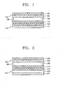
- FIG. 1 is a schematic cross-sectional view of a flexible dye-sensitized solar cell according to an embodiment of the present invention.
- the flexible solar cell includes a semiconductor electrode 110, a counter electrode 130, and an electrolyte solution 150 interposed therebetween.
- the electrolyte solution 150 can be sealed with a thermoplastic polymer material 160, such as surlyn (Dupont product 1702) to prevent leaking thereof.
- the semiconductor electrode 110 includes a conducting thin film 113 formed on a first flexible conducting substrate 111, which is composed of a metal.
- the semiconductor electrode 110 can be formed by coating ITO as a conducting material on a stainless steel to a thickness of about 1000-2000 ⁇ .
- all metals can be used in the first conducting substrate 111 because the electrolyte solution 150 can be considerably prevented from contacting a surface of the first conducting substrate 111 by the conducting thin film 113.
- a stainless steel comprising Fe as a main constituent or a Al substrate are preferably used.
- the semiconductor electrode 110 includes a nanoparticle oxide layer 114 with a thickness of 5-15 ⁇ m formed on the conducting thin film 113.
- Dye molecules composed of, for example, a Ru complex, are chemically adsorbed on the nanoparticle oxide layer 114.
- the nanoparticle oxide layer 114 is composed of TiO 2 , SnO 2 or ZnO.
- a colloidal solution of the nanoparticle oxide coated on the first conducting substrate 111 composed of a metal can be heated.
- an energy conversion efficiency of the solar cell of the present embodiment can be significantly improved when compared to other conventional flexible solar cells having a first conducting substrate composed of a polymer material, such as PET.
- the counter electrode 130 includes a Pt layer 134 formed on a second flexible conducting substrate 132 composed of a transparent polymer material.
- the Pt layer 134 is positioned so as to face the nanoparticle oxide layer 114.
- the second conducting substrate 132 is a transparent polymer substrate, such as polyethyleneterephthalate (PET, also called polyterephthalic acid ethylene), polycarbonate (also called polyester carbonate), polyimide, polyethylenenaphthalate or polyethersulfone (PES) coated with a transparent conducting material, such as ITO or F-doped SnO 2 (FTO).
- PET is a proper material to practice the present invention in view of better heat resistance, elasticity recovery and water resistance.
- Polycarbonate has better dimensional stability, light transmittance and impact resistance.
- Polyethylenenaphthalate can be used in the practice of the present invention in view of better water resistance and moisture proof property.
- the Pt layer 134 can be formed, for example, by dispersing a 5 mM hexachloroplatinic acid (H 2 PtCl 6 ⁇ x H 2 O) aqueous solution on a kind of polymer substrate as listed above and drying the solution to cover the substrate with Pt ions, then treating the resulting substrate with a 60 mM sodium borohydrate (NaBH 4 ) aqueous solution to reduce Pt ions to Pt, and finally washing the substrate with distilled water and drying.
- a 5 mM hexachloroplatinic acid H 2 PtCl 6 ⁇ x H 2 O
- NaBH 4 sodium borohydrate
- the electrolyte solution 150 can be an iodine based oxidation-reduction liquid electrolyte, for example, a l 3 - /l - electrolyte solution obtained by dissolving 0.8 M 1,2-dimethyl-3-octyl-imidazolium iodide and 40 mM iodine (l 2 ) in 3-methoxypropionitrile.
- the solar cell according to the present embodiment is operated as follows.
- the dye molecules oxidized due to the electron transition accept electrons provided by an oxidation of iodine ions (3l - ⁇ l 3 - + 2e - ) in the electrolyte solution 150.
- the oxidized iodine ions (l 3 - ) are reduced by electrons arrived at the counter electrode 130, thereby completing the operation of the dye-sensitized solar cell.
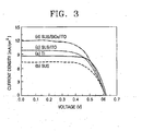
- FIG. 2 is a schematic cross-sectional view of a flexible dye-sensitized solar cell according to another embodiment of the present invention.
- the flexible solar cell according to another embodiment of the present invention includes a semiconductor electrode 210, a counter electrode 230, and an electrolyte solution 250 interposed therebetween.
- the electrolyte solution 250 can be sealed with a thermoplastic polymer material 260 to prevent leaking thereof.
- the semiconductor electrode 210 is obtained by forming an insulating thin film or semiconductor thin film 212 on a first flexible conducting substrate 211, which is composed of a metal and subsequently forming a conducting thin film (ITO or FTO) 213 thereon.
- the semiconductor electrode 110 can be obtained by coating silicon oxide (SiOx) as an insulating layer 212 on a stainless steel to a thickness of about 1000-2000 ⁇ , and subsequently coating ITO as a conducting thin film 213 thereon to a thickness of 1000-2000 ⁇ .
- the counter electrode 230 and the electrolyte solution 250 are the same as in the above embodiment.
- the conducting thin film 113 is formed on the first conducting substrate 111 as in just above embodiment, it is difficult to completely separate the electrolyte solution 150 from the metal of the first conducting substrate 111 by the conducting thin film 113 formed on the first conducting substrate 111. For extended period, the electrolyte solution 150 permeates the conducting thin film 113 formed on the first conducting substrate 111 to reach to the metal of the first conducting substrate 111, thereby inducing a voltage difference.
- the insulating thin film or semiconductor thin film 212 which can completely separate the electrolyte, is formed on the metal of the first conducting substrate 211, and then the conducting thin film 213 is formed thereon, a voltage difference due to different materials of the first conducting substrate 211 and the second conducting substrate 232 is not induced, long-period stability is improved, and energy conversion efficiency is significantly increased.
- FIG. 3 shows photocurrent-voltage characteristics of the flexible solar cells prepared according to the embodiments of the present invention and prior art.
- a 3-methoxypropionitrile solution containing 0.7 M 1-vinyl-3-methylimidazolium iodide, 0.1 M lithium iodide (LiI), 0.04 M l 2 , and 0.13 M 4-tert-butylpyridine was used as an electron solution.
- LiI lithium iodide
- FIG. 1 A 3-methoxypropionitrile solution containing 0.7 M 1-vinyl-3-methylimidazolium iodide, 0.1 M lithium iodide (LiI), 0.04 M l 2 , and 0.13 M 4-tert-butylpyridine was used as an electron solution.
- a solid line (a) is for the solar cell using a Ti substrate (such as EP1095387) as the first conducting substrate according to prior art
- a dashed line (b) is for the solar cell using a stainless steel as the first conducting substrate according to another prior art
- a dotted line (c) is for the solar cell using a stainless steel as the first conducting substrate 111 and ITO as the conducting thin film 113 according to an embodiment of the present invention
- a dotted and dashed line (d) is for the solar cell using a stainless steel as the first conducting substrate 211, SiOx as the insulating thin film 212 and ITO as the conducting thin film 213 according to another embodiment of the present invention.
- the solar cell when using the stainless steel as the first conducting substrate, the solar cell is flexible and has an energy conversion efficiency of about 3% which is lower than that of the Ti substrate.
- energy conversion efficiencies of 3.94% and 4.58% are obtained even with the stainless steel substrate. It can be confirmed that the conducting thin film and insulating thin film are applied to the stainless steel to prevent the electrolyte solution from contacting the metal of the first conducting substrate as described above, thereby improving the energy conversion efficiency.
- the present invention relates to a dye sensitized solar cell using a flexible metal substrate, a metal substrate with a conducting material coated thereon, or a metal substrate with a insulating (or semiconductor) thin film/conducting thin film formed thereon as a first conducting substrate.
- a nanoparticle oxide layer can be formed by a high temperature process, which was not possible in a conventional flexible polymer substrate.
- the nanoparticle oxide layer formed at high temperatures is very stable, and thus is not deformed or released by bending action.
- the solar cells according to the embodiments of the present invention have an improved energy conversion efficiency when compared to the conventional method and can be bended.
- the flexible solar cell including a flexible metal substrate and a thin film formed thereon has a thickness of 1 mm or less, and thus is light and can be variously applied.
- a flexible dye-sensitized solar cell is prepared by forming a nanoparticle oxide layer on the first conducting substrate as proposed in the present invention, and then applying a Pt ion solution on a second conducting polymer substrate and reducing Pt ions to form a Pt layer, the photo conversion efficiency can be significantly improved when compared to a flexible solar cell conventionally known. Since this flexible solar cell can be variously applied without significantly reducing the energy conversion efficiency compared to a conventional inflexible solar cell using a glass substrate, its commercial value are expected to be high. Further, since the polymer substrate, etc. is lighter.than a glass substrate, a light weighted solar cell can be obtained.
- a metal which has better cost competitiveness and availability compared to Zn or Ti metal, is used as a conducting metal in the present invention.
- a solar cell using a conducting glass substrate instead of the polymer substrate as the second conducting substrate is not flexible, but can be constructed.
Landscapes
- Engineering & Computer Science (AREA)
- Power Engineering (AREA)
- Microelectronics & Electronic Packaging (AREA)
- Hybrid Cells (AREA)
- Photovoltaic Devices (AREA)
Abstract
Description
- This application claims the benefit of Korean Patent Application No. 10-2004-0042213, filed on June 9, 2004, in the Korean Intellectual Property Office, the disclosure of which is incorporated herein in its entirety by reference.
- The present invention relates to a solar cell, and more particularly, to a dye-sensitized solar cell having a semiconductor electrode of a nanoparticle oxide.
- A dye-sensitized solar cell is a photoelectrochemical solar cell including photosensitive dye molecules capable of absorbing visible rays to generate an electron-hole pair and a transition metal oxide, which transfers the resulting electrons, unlike a silicon solar cell. Representative examples of the dye-sensitized solar cell known include those reported by Gratzel, et al., in U.S. Patent Nos. 4,927,721 and 5,350,644. The solar cells by Gratzel, et al. include a semiconductor electrode composed of nanoparticle titanium dioxide (TiO2), which is covered with dye molecules, a Pt electrode, and an electrolyte solution interposed therebetween. Such a cell has come into the spotlight in terms of the probability of replacing a conventional silicon solar cell due to lower production costs per power compared to the conventional silicon solar cell.
- A general semiconductor electrode of a nanoparticle oxide is completed by coating a colloidal solution of a nanoparticle oxide on a conducting glass substrate and heating the substrate in an electric furnace at 450-500°C. The heating is performed in order to increase an electric contact between nanoparticle oxides and remove a polymer added when preparing the colloidal solution to improve photoelectrical properties. The heating temperature of 450-500°C is relatively high, but the glass substrate can be used even at such a high temperature without distortion. However, it is impossible to bend a prepared solar cell in terms of characteristics of a glass substrate. Thus, application fields, which require bending, have been excluded.
- Developments and studies of a flexible dye-sensitized solar cell have been actively conducted since 2000's. Up to now, a nanoparticle oxide layer formed by coating a colloidal solution prepared by dispersing a nanoparticle oxide in a solution, such as ethanol, which is volatile at low temperatures, on a substrate and then pressing the coating by heat treatment at about 100°C and a nanoparticle oxide layer formed by coating a colloidal solution prepared using an organic dispersant on a substrate and removing the dispersant through UV irradiation and heating at about 100°C were developed. However, the above products show very low photo conversion efficiency (i.e., energy conversion efficiency) compared to the conventional dye-sensitized solar cell using a glass substrate in the high temperature process.
- A dye-sensitized solar cell having a nanoparticle oxide layer on a metal substrate of Ti or Zn as a conducting metal was reported to have a superior photo conversion efficiency (EP 1095387).
- The present invention provides a dye-sensitized solar cell which has superior energy conversion efficiency and is flexible.
- According to the present invention, there is provided a dye-sensitized solar cell including a semiconductor electrode having a first flexible conducting substrate composed of a metal, a conducting thin film formed on the first conducting substrate, a nanoparticle oxide layer formed on the conducting thin film, and dye molecules adsorbed on the nanoparticle oxide layer.
- The conducting thin film may be composed of indium tin oxide (ITO) or F-doped SnO2 (FTO). The dye-sensitized solar cell may further include an insulating thin film or semiconductor thin film between the first conducting substrate and the conducting thin film. The first conducting substrate may be a SUS or Al substrate.
- In the dye-sensitized solar cell, the second conducting substrate may be a polymer substrate of polyethyleneterephthalate, polycarbonate, polyimide, polyethylenenaphthalate or polyethersulfone coated with a conducting material, such as ITO or FTO. The nanoparticle oxide layer may be a layer of TiO2, SnO2 or ZnO.
- The above and other features and advantages of the present invention will become more apparent by describing in detail exemplary embodiments thereof with reference to the attached drawings in which:
- FIG. 1 is a schematic cross-sectional view of a flexible dye-sensitized solar cell according to an embodiment of the present invention;
- FIG. 2 is a schematic cross-sectional view of a flexible dye-sensitized solar cell according to another embodiment of the present invention; and
- FIG. 3 illustrates photocurrent-voltage curves of the dye-sensitized solar cells of FIGS. 1 and 2.
-
- The present invention will now be described more fully with reference to the accompanying drawings, in which exemplary embodiments of the invention are shown. The invention may, however, be embodied in many different forms and should not be construed as being limited to the embodiments set forth herein; rather, these embodiments are provided so that this disclosure will be thorough and complete, and will fully convey the concept of the invention to those skilled in the art.
- FIG. 1 is a schematic cross-sectional view of a flexible dye-sensitized solar cell according to an embodiment of the present invention.
- Referring to FIG. 1, the flexible solar cell according to an embodiment of the present invention includes a
semiconductor electrode 110, acounter electrode 130, and anelectrolyte solution 150 interposed therebetween. Theelectrolyte solution 150 can be sealed with athermoplastic polymer material 160, such as surlyn (Dupont product 1702) to prevent leaking thereof. - The
semiconductor electrode 110 includes a conductingthin film 113 formed on a first flexible conductingsubstrate 111, which is composed of a metal. For example, thesemiconductor electrode 110 can be formed by coating ITO as a conducting material on a stainless steel to a thickness of about 1000-2000 Å. However, all metals can be used in the first conductingsubstrate 111 because theelectrolyte solution 150 can be considerably prevented from contacting a surface of the first conductingsubstrate 111 by the conductingthin film 113. In view of costs and resource deposits, a stainless steel comprising Fe as a main constituent or a Al substrate are preferably used. - The
semiconductor electrode 110 includes ananoparticle oxide layer 114 with a thickness of 5-15 µm formed on the conductingthin film 113. Dye molecules composed of, for example, a Ru complex, are chemically adsorbed on thenanoparticle oxide layer 114. Thenanoparticle oxide layer 114 is composed of TiO2, SnO2 or ZnO. - In the solar cell of the present embodiment, a colloidal solution of the nanoparticle oxide coated on the first conducting
substrate 111 composed of a metal can be heated. Thus, an energy conversion efficiency of the solar cell of the present embodiment can be significantly improved when compared to other conventional flexible solar cells having a first conducting substrate composed of a polymer material, such as PET. - The
counter electrode 130 includes aPt layer 134 formed on a second flexible conductingsubstrate 132 composed of a transparent polymer material. ThePt layer 134 is positioned so as to face thenanoparticle oxide layer 114. The second conductingsubstrate 132 is a transparent polymer substrate, such as polyethyleneterephthalate (PET, also called polyterephthalic acid ethylene), polycarbonate (also called polyester carbonate), polyimide, polyethylenenaphthalate or polyethersulfone (PES) coated with a transparent conducting material, such as ITO or F-doped SnO2 (FTO). PET is a proper material to practice the present invention in view of better heat resistance, elasticity recovery and water resistance. Polycarbonate has better dimensional stability, light transmittance and impact resistance. Polyethylenenaphthalate can be used in the practice of the present invention in view of better water resistance and moisture proof property. - When the same conducting
thin film 113 as the conducting material of the second conductingsubstrate 132 is formed on the first conductingsubstrate 111, a voltage difference due to different materials of the first conductingsubstrate 111 and the second conductingsubstrate 132 cannot be induced, thereby improving the energy conversion efficiency. - The
Pt layer 134 can be formed, for example, by dispersing a 5 mM hexachloroplatinic acid (H2PtCl6 · xH2O) aqueous solution on a kind of polymer substrate as listed above and drying the solution to cover the substrate with Pt ions, then treating the resulting substrate with a 60 mM sodium borohydrate (NaBH4) aqueous solution to reduce Pt ions to Pt, and finally washing the substrate with distilled water and drying. - The
electrolyte solution 150 can be an iodine based oxidation-reduction liquid electrolyte, for example, a l3 - /l- electrolyte solution obtained by dissolving 0.8 M 1,2-dimethyl-3-octyl-imidazolium iodide and 40 mM iodine (l2) in 3-methoxypropionitrile. - The solar cell according to the present embodiment is operated as follows.
- Light transmitted to the second transparent conducting
substrate 132 of thecounter electrode 130 is passed through thePt layer 134, and then absorbed by dye molecules, which are adsorbed on thenanoparticle oxide layer 114. Then, an electron transition of dye molecules from the ground state to the excited state occurs to form electron-hole pairs and the excited electrons are injected to a conduction band of thenanoparticle oxide layer 114. The electrons injected to thenanoparticle oxide layer 114 are transferred to the first conductingsubstrate 111, which contacts thenanoparticle oxide layer 114, through an interface between particles. Then, the electrons migrate to the counter electrode 30 through an external electric wire (not shown). The dye molecules oxidized due to the electron transition accept electrons provided by an oxidation of iodine ions (3l- → l3 - + 2e-) in theelectrolyte solution 150. The oxidized iodine ions (l3 - ) are reduced by electrons arrived at thecounter electrode 130, thereby completing the operation of the dye-sensitized solar cell. - FIG. 2 is a schematic cross-sectional view of a flexible dye-sensitized solar cell according to another embodiment of the present invention.
- Referring to FIG. 2, the flexible solar cell according to another embodiment of the present invention includes a
semiconductor electrode 210, acounter electrode 230, and anelectrolyte solution 250 interposed therebetween. Theelectrolyte solution 250 can be sealed with athermoplastic polymer material 260 to prevent leaking thereof. - The
semiconductor electrode 210 is obtained by forming an insulating thin film or semiconductorthin film 212 on a firstflexible conducting substrate 211, which is composed of a metal and subsequently forming a conducting thin film (ITO or FTO) 213 thereon. For example, thesemiconductor electrode 110 can be obtained by coating silicon oxide (SiOx) as an insulatinglayer 212 on a stainless steel to a thickness of about 1000-2000 Å, and subsequently coating ITO as a conductingthin film 213 thereon to a thickness of 1000-2000 Å. Thecounter electrode 230 and theelectrolyte solution 250 are the same as in the above embodiment. - Although the conducting
thin film 113 is formed on thefirst conducting substrate 111 as in just above embodiment, it is difficult to completely separate theelectrolyte solution 150 from the metal of thefirst conducting substrate 111 by the conductingthin film 113 formed on thefirst conducting substrate 111. For extended period, theelectrolyte solution 150 permeates the conductingthin film 113 formed on thefirst conducting substrate 111 to reach to the metal of thefirst conducting substrate 111, thereby inducing a voltage difference. - Thus, when the insulating thin film or semiconductor
thin film 212, which can completely separate the electrolyte, is formed on the metal of thefirst conducting substrate 211, and then the conductingthin film 213 is formed thereon, a voltage difference due to different materials of thefirst conducting substrate 211 and thesecond conducting substrate 232 is not induced, long-period stability is improved, and energy conversion efficiency is significantly increased. - Solar cells were prepared according to the methods described above, and then, comparison of characteristics with prior art (EP1095387 etc.) was conducted. FIG. 3 shows photocurrent-voltage characteristics of the flexible solar cells prepared according to the embodiments of the present invention and prior art.
- A 3-methoxypropionitrile solution containing 0.7 M 1-vinyl-3-methylimidazolium iodide, 0.1 M lithium iodide (LiI), 0.04 M l2, and 0.13 M 4-tert-butylpyridine was used as an electron solution. In FIG. 3, a solid line (a) is for the solar cell using a Ti substrate (such as EP1095387) as the first conducting substrate according to prior art, a dashed line (b) is for the solar cell using a stainless steel as the first conducting substrate according to another prior art, a dotted line (c) is for the solar cell using a stainless steel as the
first conducting substrate 111 and ITO as the conductingthin film 113 according to an embodiment of the present invention, and a dotted and dashed line (d) is for the solar cell using a stainless steel as thefirst conducting substrate 211, SiOx as the insulatingthin film 212 and ITO as the conductingthin film 213 according to another embodiment of the present invention. - The photoelectrical characteristics calculated from FIG. 3 are given in Table 1.
Structure of semiconductor electrode Photocurrent density mA/cm2 Photovoltage V Efficiency % Ti 8.14 0.62 3.60 Stainless steel 7.57 0.61 3.09 Stainless steel/conducting thin film (ITO) 10.2 0.61 3.94 Stainless steel/insulating thin film (SiOx) /conducting thin film (ITO) 12.3 0.61 4.58 - As apparent from FIG. 3 and Table 1, when using the stainless steel as the first conducting substrate, the solar cell is flexible and has an energy conversion efficiency of about 3% which is lower than that of the Ti substrate. However, according to the present invention, energy conversion efficiencies of 3.94% and 4.58% are obtained even with the stainless steel substrate. It can be confirmed that the conducting thin film and insulating thin film are applied to the stainless steel to prevent the electrolyte solution from contacting the metal of the first conducting substrate as described above, thereby improving the energy conversion efficiency.
- As describe above, the present invention relates to a dye sensitized solar cell using a flexible metal substrate, a metal substrate with a conducting material coated thereon, or a metal substrate with a insulating (or semiconductor) thin film/conducting thin film formed thereon as a first conducting substrate. In the dye sensitized solar cell, a nanoparticle oxide layer can be formed by a high temperature process, which was not possible in a conventional flexible polymer substrate. The nanoparticle oxide layer formed at high temperatures is very stable, and thus is not deformed or released by bending action. Thus, the solar cells according to the embodiments of the present invention have an improved energy conversion efficiency when compared to the conventional method and can be bended. The flexible solar cell including a flexible metal substrate and a thin film formed thereon has a thickness of 1 mm or less, and thus is light and can be variously applied.
- When a flexible dye-sensitized solar cell is prepared by forming a nanoparticle oxide layer on the first conducting substrate as proposed in the present invention, and then applying a Pt ion solution on a second conducting polymer substrate and reducing Pt ions to form a Pt layer, the photo conversion efficiency can be significantly improved when compared to a flexible solar cell conventionally known. Since this flexible solar cell can be variously applied without significantly reducing the energy conversion efficiency compared to a conventional inflexible solar cell using a glass substrate, its commercial value are expected to be high. Further, since the polymer substrate, etc. is lighter.than a glass substrate, a light weighted solar cell can be obtained.
- In addition, a metal, which has better cost competitiveness and availability compared to Zn or Ti metal, is used as a conducting metal in the present invention.
- While the present invention has been particularly shown and described with reference to exemplary embodiments thereof, it will be understood by those of ordinary skill in the art that various changes in form and details may be made therein without departing from the spirit and scope of the present invention as defined by the following claims. For example, a solar cell using a conducting glass substrate instead of the polymer substrate as the second conducting substrate is not flexible, but can be constructed.
Claims (11)
- A dye-sensitized solar cell comprising:a semiconductor electrode including a first flexible conducting substrate composed of a metal, a conducting thin film formed on the first conducting substrate, an nanoparticle oxide layer formed on the conducting thin film, and dye molecules adsorbed on the nanoparticle oxide layer;a counter electrode including a second flexible conducting substrate composed of a flexible transparent polymer and a Pt layer formed on the second conducting substrate; andan electrolyte solution interposed between the semiconductor electrode and the counter electrode.
- The dye-sensitized solar cell of claim 1, wherein the conducting thin film is composed of indium tin oxide (ITO) or F-doped SnO2 (FTO).
- The dye-sensitized solar cell of claim 1, further comprising an insulating thin film or semiconductor thin film between the first conducting substrate and the conducting thin film.
- The dye-sensitized solar cell of claim 1, wherein the first conducting substrate is a stainless steel substrate or Al substrate.
- The dye-sensitized solar cell of claim 1, wherein the second conducting substrate is a polymer substrate of polyethyleneterephthalate, polycarbonate, polyimide, polyethylenenaphthalate or polyethersulfone coated with a conducting material.
- The dye-sensitized solar cell of claim 5, wherein the conducting material is ITO or FTO.
- The dye-sensitized solar cell of claim 1, wherein the nanoparticle oxide layer is a layer of TiO2, SnO2 or ZnO.
- The dye-sensitized solar cell of claim 3, wherein the first conducting substrate is a stainless steel substrate or Al substrate.
- The dye-sensitized solar cell of claim 3, wherein the second conducting substrate is a polymer substrate of polyethyleneterephthalate, polycarbonate, polyimide, polyethylenenaphthalate or polyethersulfone coated with a conducting material.
- The dye-sensitized solar cell of claim 9, wherein the conducting material is indium tin oxide (ITO) or F-doped SnO2 (FTO).
- The dye-sensitized solar cell of claim 3, wherein the nanoparticle oxide layer is a layer of TiO2, SnO2 or ZnO.
Applications Claiming Priority (2)
| Application Number | Priority Date | Filing Date | Title |
|---|---|---|---|
| KR1020040042213A KR100554179B1 (en) | 2004-06-09 | 2004-06-09 | Bendable Dye-Sensitized Solar Cell Including a Conductive Metal Substrate |
| KR2004042213 | 2004-06-09 |
Publications (2)
| Publication Number | Publication Date |
|---|---|
| EP1605479A2 true EP1605479A2 (en) | 2005-12-14 |
| EP1605479A3 EP1605479A3 (en) | 2009-12-09 |
Family
ID=34940652
Family Applications (1)
| Application Number | Title | Priority Date | Filing Date |
|---|---|---|---|
| EP05251936A Withdrawn EP1605479A3 (en) | 2004-06-09 | 2005-03-29 | Flexible dye-sentitized solar cell using conducting metal substrate |
Country Status (4)
| Country | Link |
|---|---|
| US (1) | US20050274412A1 (en) |
| EP (1) | EP1605479A3 (en) |
| JP (1) | JP4343874B2 (en) |
| KR (1) | KR100554179B1 (en) |
Cited By (7)
| Publication number | Priority date | Publication date | Assignee | Title |
|---|---|---|---|---|
| WO2010107795A1 (en) * | 2009-03-17 | 2010-09-23 | Konarka Technologies, Inc. | Metal substrate for a dye sensitized photovoltaic cell |
| WO2010128461A1 (en) * | 2009-05-07 | 2010-11-11 | Solargenius S.R.L. | Therminal contacts photovoltaic modules |
| WO2011009574A3 (en) * | 2009-07-23 | 2011-03-24 | Corus Uk Limited | A conductive layer for use in a photovoltaic device or other electronic application |
| CN102292291A (en) * | 2009-01-12 | 2011-12-21 | 科学与工业研究委员会 | "high efficient dye-sensitized solar cells using tio2- multiwalled carbon nano tube (mwcnt) nanocomposite" |
| WO2012100930A1 (en) * | 2011-01-24 | 2012-08-02 | Tata Steel Uk Limited | Flexible dye sensitised solar cell and a method for manufacturing the same |
| CN104616896A (en) * | 2015-02-05 | 2015-05-13 | 上海工程技术大学 | Self-supported titanium nitride/graphene combined electrode and preparation method thereof |
| TWI487131B (en) * | 2007-09-14 | 2015-06-01 | Hon Hai Prec Ind Co Ltd | Apparatus and method for making solar cell |
Families Citing this family (34)
| Publication number | Priority date | Publication date | Assignee | Title |
|---|---|---|---|---|
| JP5084170B2 (en) * | 2006-05-09 | 2012-11-28 | グンゼ株式会社 | Method for producing transparent electrode substrate for dye-sensitized solar cell |
| EP2190056B1 (en) * | 2006-08-24 | 2014-10-01 | Toyo Seikan Kaisha, Ltd. | Dye-sensitized solar cell |
| JP5109308B2 (en) * | 2006-08-24 | 2012-12-26 | 東洋製罐株式会社 | Dye-sensitized solar cell |
| KR100911381B1 (en) * | 2007-07-31 | 2009-08-10 | 한국전자통신연구원 | Method for producing porous thin film, dye-sensitized solar cell using same and method for manufacturing same |
| KR100867994B1 (en) * | 2007-10-18 | 2008-11-10 | 한국전자통신연구원 | IP-based two-way advertising transmission method and apparatus |
| KR20090051597A (en) | 2007-11-19 | 2009-05-22 | 한국전자통신연구원 | Dye-Sensitized Solar Cells Using Conductive Fiber Electrodes |
| AU2009210979A1 (en) * | 2008-02-06 | 2009-08-13 | Fujikura Ltd. | Dye-sensitized solar cell |
| JP5251298B2 (en) * | 2008-07-02 | 2013-07-31 | セイコーエプソン株式会社 | Method for producing transparent conductive film |
| NL2001815C2 (en) * | 2008-07-17 | 2010-01-19 | Stichting Energie | Reversed dye-sensitized photovoltaic cell. |
| WO2010037554A2 (en) * | 2008-10-02 | 2010-04-08 | Corus Uk Limited | A method of manufacturing a photovoltaic device, an intermediate manufacturing product and a photovoltaic device |
| US20100139761A1 (en) * | 2008-12-08 | 2010-06-10 | Electronics And Telecommunications Research Institute | Dye-sensitized solar cell and method of fabricating the same |
| KR101034640B1 (en) * | 2009-01-30 | 2011-05-16 | 한국과학기술연구원 | Photoelectrode comprising nanoparticle metal oxide-polymer composite for dye-sensitized solar cell, method for producing same, and dye-sensitized solar cell using same |
| JP2010277999A (en) * | 2009-06-01 | 2010-12-09 | Korea Electronics Telecommun | Dye-sensitized solar cell and manufacturing method thereof |
| JP4620794B1 (en) * | 2010-03-11 | 2011-01-26 | 大日本印刷株式会社 | Dye-sensitized solar cell |
| KR101339439B1 (en) | 2010-06-22 | 2013-12-10 | 한국전자통신연구원 | Solar Cell and Method of The Same |
| KR101491244B1 (en) * | 2012-04-10 | 2015-02-06 | 포항공과대학교 산학협력단 | Organic ight emitting diode including integral and conductive substrate |
| KR101476907B1 (en) * | 2012-04-10 | 2014-12-26 | 포항공과대학교 산학협력단 | Integral and conductive substrate and electric device including the same |
| WO2013154354A1 (en) * | 2012-04-10 | 2013-10-17 | 포항공과대학교 산학협력단 | Integrated conductive substrate, and electronic device employing same |
| WO2013154355A1 (en) * | 2012-04-10 | 2013-10-17 | 포항공과대학교 산학협력단 | Integrated conductive substrate, and electronic device employing same |
| KR101439601B1 (en) * | 2012-06-27 | 2014-09-16 | 주식회사 포스코 | Method for manufacturing solar cell substrate having insulation property |
| KR101439600B1 (en) * | 2012-06-27 | 2014-09-16 | 주식회사 포스코 | Method for manufacturing solar cell substrate having insulation property |
| CN103903863A (en) * | 2012-12-27 | 2014-07-02 | 中国科学院上海硅酸盐研究所 | Method for preparing dye-sensitized solar cell by rapidly adsorbing dyes |
| CN103606464B (en) * | 2013-10-26 | 2017-01-11 | 皖江新兴产业技术发展中心 | Method and device for rapid and uniform sensitization of photo anode of dye-sensitized solar cell |
| CN103779101A (en) * | 2014-01-07 | 2014-05-07 | 浙江大学 | Hybrid solid solar cell and preparation method thereof |
| CN103887071B (en) * | 2014-03-13 | 2016-09-14 | 四川材料与工艺研究所 | A kind of flexible dye-sensitized solar battery nanometer paper substrate complex light anode and preparation method thereof |
| CN103928236B (en) * | 2014-04-29 | 2017-01-25 | 攀枝花学院 | Method for preparing dye-sensitized solar cell vanadium-doped composite electrode |
| CN104282442B (en) * | 2014-10-17 | 2017-09-29 | 华中科技大学 | A kind of DSSC photocathode and its preparation method and application |
| CN104465116A (en) * | 2014-12-30 | 2015-03-25 | 中国科学院上海硅酸盐研究所 | Counter electrode of dye-sensitized solar cell and preparation method of counter electrode |
| CN104992838B (en) * | 2015-07-13 | 2017-11-07 | 广西大学 | A kind of preparation method of zinc oxide absorbing membrane |
| CN107481862A (en) * | 2017-08-04 | 2017-12-15 | 京东方科技集团股份有限公司 | Purposes, DSSC and the preparation method of metal nanoparticle |
| CN107633950A (en) * | 2017-09-20 | 2018-01-26 | 陈卓 | It is a kind of to be used for the compound carbon-based to electrode and preparation method thereof of DSSC |
| CN108538604A (en) * | 2018-04-02 | 2018-09-14 | 深圳汇创联合自动化控制有限公司 | A kind of solar cell module |
| CN109980027B (en) * | 2019-04-02 | 2020-10-23 | 江苏荣马新能源有限公司 | Solar cell with high conversion rate |
| CN113540357B (en) * | 2021-06-21 | 2024-02-23 | 南京邮电大学 | Flexible organic solar cell and preparation method thereof |
Citations (3)
| Publication number | Priority date | Publication date | Assignee | Title |
|---|---|---|---|---|
| US4927721A (en) | 1988-02-12 | 1990-05-22 | Michael Gratzel | Photo-electrochemical cell |
| US5350644A (en) | 1990-04-17 | 1994-09-27 | Ecole Polytechnique, Federale De Lausanne | Photovoltaic cells |
| EP1095387A1 (en) | 1998-06-18 | 2001-05-02 | Stichting Energieonderzoek Centrum Nederland(ECN) | Reversed dye-sensitized photovoltaic cell |
Family Cites Families (12)
| Publication number | Priority date | Publication date | Assignee | Title |
|---|---|---|---|---|
| EP0078541B1 (en) * | 1981-11-04 | 1991-01-16 | Kanegafuchi Kagaku Kogyo Kabushiki Kaisha | Flexible photovoltaic device |
| EP0948004A1 (en) * | 1998-03-26 | 1999-10-06 | Akzo Nobel N.V. | Method for making a photovoltaic cell containing a dye |
| JPH11312541A (en) | 1998-04-30 | 1999-11-09 | Minolta Co Ltd | Solar cell |
| JP2000164909A (en) * | 1998-11-30 | 2000-06-16 | Nisshin Steel Co Ltd | Thin-film solar cell and manufacture of it |
| US6291763B1 (en) * | 1999-04-06 | 2001-09-18 | Fuji Photo Film Co., Ltd. | Photoelectric conversion device and photo cell |
| US6479745B2 (en) * | 2000-01-26 | 2002-11-12 | Sharp Kabushiki Kaisha | Dye-sensitized solar cell and method of manufacturing the same |
| SE0103740D0 (en) * | 2001-11-08 | 2001-11-08 | Forskarpatent I Vaest Ab | Photovoltaic element and production methods |
| JP4659954B2 (en) | 2000-09-19 | 2011-03-30 | 大日本印刷株式会社 | Method for producing dye-sensitized solar cell and method for producing dye-sensitized solar cell module |
| JP4285627B2 (en) | 2001-02-21 | 2009-06-24 | 昭和電工株式会社 | Photoactive electrode for dye-sensitized solar cell and method for producing the same |
| KR100462006B1 (en) * | 2001-03-30 | 2004-12-17 | 태원필 | SnO2/TiO2 coupled oxide semiconductor and dye-sensitized solar cell |
| JP2003132964A (en) | 2001-10-26 | 2003-05-09 | Matsushita Electric Works Ltd | Dye-sensitized solar cell and manufacturing method thereof |
| KR100543218B1 (en) * | 2003-10-31 | 2006-01-20 | 한국과학기술연구원 | Dye-sensitized solar cell having semiconductor electrode made of electrospun ultrafine titanium oxide fibers and method for manufacturing same |
-
2004
- 2004-06-09 KR KR1020040042213A patent/KR100554179B1/en not_active Expired - Fee Related
-
2005
- 2005-03-25 US US11/089,631 patent/US20050274412A1/en not_active Abandoned
- 2005-03-29 EP EP05251936A patent/EP1605479A3/en not_active Withdrawn
- 2005-05-30 JP JP2005157700A patent/JP4343874B2/en not_active Expired - Fee Related
Patent Citations (3)
| Publication number | Priority date | Publication date | Assignee | Title |
|---|---|---|---|---|
| US4927721A (en) | 1988-02-12 | 1990-05-22 | Michael Gratzel | Photo-electrochemical cell |
| US5350644A (en) | 1990-04-17 | 1994-09-27 | Ecole Polytechnique, Federale De Lausanne | Photovoltaic cells |
| EP1095387A1 (en) | 1998-06-18 | 2001-05-02 | Stichting Energieonderzoek Centrum Nederland(ECN) | Reversed dye-sensitized photovoltaic cell |
Cited By (9)
| Publication number | Priority date | Publication date | Assignee | Title |
|---|---|---|---|---|
| TWI487131B (en) * | 2007-09-14 | 2015-06-01 | Hon Hai Prec Ind Co Ltd | Apparatus and method for making solar cell |
| CN102292291A (en) * | 2009-01-12 | 2011-12-21 | 科学与工业研究委员会 | "high efficient dye-sensitized solar cells using tio2- multiwalled carbon nano tube (mwcnt) nanocomposite" |
| WO2010107795A1 (en) * | 2009-03-17 | 2010-09-23 | Konarka Technologies, Inc. | Metal substrate for a dye sensitized photovoltaic cell |
| WO2010128461A1 (en) * | 2009-05-07 | 2010-11-11 | Solargenius S.R.L. | Therminal contacts photovoltaic modules |
| WO2011009574A3 (en) * | 2009-07-23 | 2011-03-24 | Corus Uk Limited | A conductive layer for use in a photovoltaic device or other electronic application |
| WO2012100930A1 (en) * | 2011-01-24 | 2012-08-02 | Tata Steel Uk Limited | Flexible dye sensitised solar cell and a method for manufacturing the same |
| GB2504414A (en) * | 2011-01-24 | 2014-01-29 | Tata Steel Uk Ltd | Flexible dye sensitised solar cell and a method for manufacturing the same |
| GB2504414B (en) * | 2011-01-24 | 2014-09-03 | Univ Swansea | Flexible dye sensitised solar cell and a method for manufacturing the same |
| CN104616896A (en) * | 2015-02-05 | 2015-05-13 | 上海工程技术大学 | Self-supported titanium nitride/graphene combined electrode and preparation method thereof |
Also Published As
| Publication number | Publication date |
|---|---|
| JP2005353588A (en) | 2005-12-22 |
| US20050274412A1 (en) | 2005-12-15 |
| JP4343874B2 (en) | 2009-10-14 |
| KR20050117041A (en) | 2005-12-14 |
| KR100554179B1 (en) | 2006-02-22 |
| EP1605479A3 (en) | 2009-12-09 |
Similar Documents
| Publication | Publication Date | Title |
|---|---|---|
| US20050274412A1 (en) | Flexible dye-sensitized solar cell using conducting metal substrate | |
| JP5140588B2 (en) | Dye-sensitized solar cell module and manufacturing method thereof | |
| JP5422645B2 (en) | Dye-sensitized solar cell and dye-sensitized solar cell module | |
| JP4488034B2 (en) | Dye-sensitized solar cell | |
| CN102077410B (en) | Dye-sensitized solar cell, method for manufacturing dye-sensitized solar cell, and dye-sensitized solar cell module | |
| US20090032104A1 (en) | Dye-sensitized solar cell having improved energy conversion efficiency and method of fabricating the same | |
| WO2011096154A1 (en) | Dye-sensitized solar cell and method for manufacturing the same | |
| US20090101198A1 (en) | Dye-sensitized solar cell and method of fabricating the same | |
| JP2004363069A (en) | Semiconductor electrode, manufacturing method thereof, and dye-sensitized solar cell using same | |
| KR100572852B1 (en) | Bendable solar cell and its manufacturing method | |
| JP4892186B2 (en) | Dye-sensitized solar cell and dye-sensitized solar cell module | |
| KR100656357B1 (en) | Transparent conductive substrate including metal grid and dye-sensitized solar cell having same | |
| KR100734853B1 (en) | Dye-sensitized solar cell using conducting metal substrates as an anode and fabrication method thereof | |
| JP5128118B2 (en) | Wet solar cell and manufacturing method thereof | |
| JP2006073488A (en) | Dye-sensitized solar cell and manufacturing method thereof | |
| KR100567330B1 (en) | Dual Structure Dye-Sensitized Solar Cell | |
| JP2005243379A (en) | Photoelectric conversion device | |
| JP4966525B2 (en) | Dye-sensitized solar cell, its photoelectrode substrate, and method for producing the photoelectrode substrate | |
| KR101256473B1 (en) | Electrode plate and dye-sensitized solar cell having the same, and method for manufacturing the same | |
| JP5135520B2 (en) | Dye-sensitized solar cell | |
| KR100499271B1 (en) | Flexible dye-sensitized solar cells and method for manufacturing the same | |
| JP4841574B2 (en) | Dye-sensitized solar cell module and manufacturing method thereof | |
| JP2005071956A (en) | Base material used for dye sensitized solar cell, and manufacturing method of dye sensitized solar cell | |
| JP2004119129A (en) | Manufacturing method of dye-sensitized solar cell and dye-sensitized solar cell obtained by the method | |
| JP2004241234A (en) | Optical electrode and dye-sensitized solar cell using it |
Legal Events
| Date | Code | Title | Description |
|---|---|---|---|
| PUAI | Public reference made under article 153(3) epc to a published international application that has entered the european phase |
Free format text: ORIGINAL CODE: 0009012 |
|
| 17P | Request for examination filed |
Effective date: 20050416 |
|
| AK | Designated contracting states |
Kind code of ref document: A2 Designated state(s): AT BE BG CH CY CZ DE DK EE ES FI FR GB GR HU IE IS IT LI LT LU MC NL PL PT RO SE SI SK TR |
|
| AX | Request for extension of the european patent |
Extension state: AL BA HR LV MK YU |
|
| PUAL | Search report despatched |
Free format text: ORIGINAL CODE: 0009013 |
|
| AK | Designated contracting states |
Kind code of ref document: A3 Designated state(s): AT BE BG CH CY CZ DE DK EE ES FI FR GB GR HU IE IS IT LI LT LU MC NL PL PT RO SE SI SK TR |
|
| AX | Request for extension of the european patent |
Extension state: AL BA HR LV MK YU |
|
| 17Q | First examination report despatched |
Effective date: 20100217 |
|
| AKX | Designation fees paid |
Designated state(s): AT BE BG CH CY CZ DE DK EE ES FI FR GB GR HU IE IS IT LI LT LU MC NL PL PT RO SE SI SK TR |
|
| GRAP | Despatch of communication of intention to grant a patent |
Free format text: ORIGINAL CODE: EPIDOSNIGR1 |
|
| RAP1 | Party data changed (applicant data changed or rights of an application transferred) |
Owner name: ELECTRONICS AND TELECOMMUNICATIONS RESEARCH INSTIT |
|
| INTG | Intention to grant announced |
Effective date: 20150303 |
|
| STAA | Information on the status of an ep patent application or granted ep patent |
Free format text: STATUS: THE APPLICATION IS DEEMED TO BE WITHDRAWN |
|
| 18D | Application deemed to be withdrawn |
Effective date: 20150714 |